

Page 1

TRANSPAK
GPS Personal Navigator
Operation &
Maintenance Guide
TrimbleNavigation
Page 2

Limited Warranty
Trimble Navigation Limited warrants its products to be free from defects in
material and workmanship for a period of one year from the date of sale by our
authorized dealers to an original purchaser or subsequent owner.
This warranty covers repair and/or replacement, at our option, of any part or
parts found to be defective, provided such defects, in our opinion, are due
to
faulty material or workmanship and are not caused by unauthorized or
improper
repair or abuse, or normal wear. Buyer shall be responsible for
shipping and
insurance of all products returned for repair under this
warranty. Trimble
Navigation will pay shipping and insurance for all TNL
products returned to
buyer provided that the products returned prove
defective under this warranty.
This warranty applies only to products in normal use. lt does not apply to
units
or circuit boards defective due to improper installation, physical
damage,
lightning or other electrical discharge, or units subjected to fresh or
salt water
immersion or spray.
The foregoing are the only warranties expressed or implied. No other warranties
exist.
Trimble Navigation assumes no responsibility for any consequential or incidental losses or damages of any nature with respect to any products or service sold,
rendered or delivered.
Trimble Navigation may not warrant any product without proof of proper
installation by an authorized Trimble dealer.
TRANSPAK is a trademark of Trimble Navigation Limited
MANUAL IMPROVEMENT
Please help improve our manuals by sending comments and
suggestions to our headquarters in Sunnyvale, California
(see
address on the rear cover).
Thank you.
WARRANTY
As an expression of confidence in our products to continue
meeting the high standards of reliability and performance that
our customers have come to expect, Trimble Navigation products are covered by the following limited warranty.
Page 3

TRANSPAK
GPS Personal Navigator
Operation &
Maintenance Guide
Part Number TNL 16141
Printed in USA
January 1990
Copyright © 1990 Trimble Navigation Limited
All rights reserved
Page 4

EDT
English
ETA
ETE
EXT
FIX
GMT
GPS
GS
HDG
INC
INT
Km
KPH
KTS
LAT
LCD
LOC
LON
m
M
Metric
MG
MI
MPH
NAD
Nautical
NM
POS
R/B
REM
RNG
SOG
SV
STS
T
Tr
TTG
UTC
VEL
WPT
XTE
2D
3D
Liquid Crystal Display
Local time
Longitude
Meters
Magnetic north
reference
Metric units of measure
Magnetic north
reference
Miles
Miles per hour
North American Datum
Nautical units of
measure
Nautical mile
Position
Range and bearing
Time remaining
Range
Speed over ground
Space vehicle or
satellite
Status
True north reference
True north reference
Time to go
Universal Coordinated
Time (same as GMT)
Velocity
Waypoint
Crosstrack error
Two dimensional
Three dimensional
Months of the year: JAN FEB MAR etc.
Days of the week: SUN MON TUE WED THU FRI SAT
Latitude and Longitude hemispheres:
N (north)
Altitude
Automatic 2D/3D
Bearing
Crosstrack distance
indicator
Clear
Course over ground
Decrement
Degrees
Distance
Degree, Minutes,
Decimal Minutes
coordinate system
Edit
English units of
measure
Estimated time of
arrival
Estimated time enroute
External
Position fix
Greenwich Mean Time
Global Positioning
System
Ground Speed
Heading
Increment
Internal
Kilometers
Kilometers per hour
Knots
Latitude
S (south) E (east) W (west)
Great Circle: The shortest distance between two points on the
surface of a sphere.
ii
GLOSSARY
The following abbreviations are used in this manual:
ALT
AUTO
BRG
CDI
CLR
COG
DEC
DEG
DIST
DM.
Page 5

iii
INTRODUCTION
Congratulations on your selection of the Trimble Navigation
TRANSPAK GPS Personal Navigator! The
TRANSPAK
is a
rugged, portable navigation device which receives and uses
signals from the Global Positioning System (GPS) satellites to
determine the time of day and your position, velocity, distance
from locations, and time of arrival at a destination.
The
TRANSPAK
is a three-channel receiver that can track two
satellites on two channels while sequencing on the third channel.
This provides very stable velocity, heading and position solu-
tions under acceleration. In addition, LAND, SEA, or AIR
modes can be selected to optimize the receiver dynamics
for land, sea, or air navigation situations.
Your
TRANSPAK
was fully tested at the factory and will provide
years of trouble-free operation.
Page 6

iv
ABOUT THIS MANUAL
This manual provides information to quickly familiarize you
with the
TRANSPAK
and enable you to use it to perform positioning
and navigation functions.
The manual is arranged in three main parts:
Description: describes the Global Positioning System (GPS)
and the
TRANSPAK
receiver, identifies the controls, indicators, and
connectors, and defines basic operations.
Operation:
describes how to prepare the
TRANSPAK
for use,
defines the functions it can perform, and provides essential
information for each of the display formats.
Maintenance and Reference:
describes operator maintenance
and provides a list of the reference datums built into the unit.
The manual is organized for ease of use. In most cases,
example screens or figures are presented on the left-hand
page, and the corresponding text is located on the righthand page. In the Operation section, the descriptions of the
operations are arranged in the same order as the rotary
switch positions which select them.
For clarity, the same abbreviations displayed by the unit are used
throughout the manual; refer to the Glossary for their meanings.
Page 7

v
TABLE OF CONTENTS
Glossary
.........................................................
ii
Introduction
...................................................
iii
About This Manual
.......................................
iv
1: DESCRIPTION
GPS and the
TRANSPAK
.................................................
1
Controls and Indicators
.................................
2
Other Parts and Accessories
.........................
4
Coordinate System
.........................................
6
2: OPERATION
Rotary Knob Position
...................................
8
How to Change Data
.....................................
10
Turn On/Off
...................................................
12
Getting Started: Your First GPS Fix
............
14
POS
................................................................
16
NAV
..............................................................
20
TIME
.............................................................
26
DIST ..............................................................
28
WPT
...............................................................
30
STS.
...............................................................
36
SETUP ...........................................................
38
3:
MAINTENANCE AND REFERENCE
Maintenance
..................................................
40
Troubleshooting the
TRANSPAK
.......................
44
Datum Selections
...........................................
46
Safety
............................................................
Inside rear cover
Page 8
GPS and the TRANSPAK
Page 9

1
GPS and the TRANSPAK
GLOBAL POSITIONING SYSTEM (GPS)
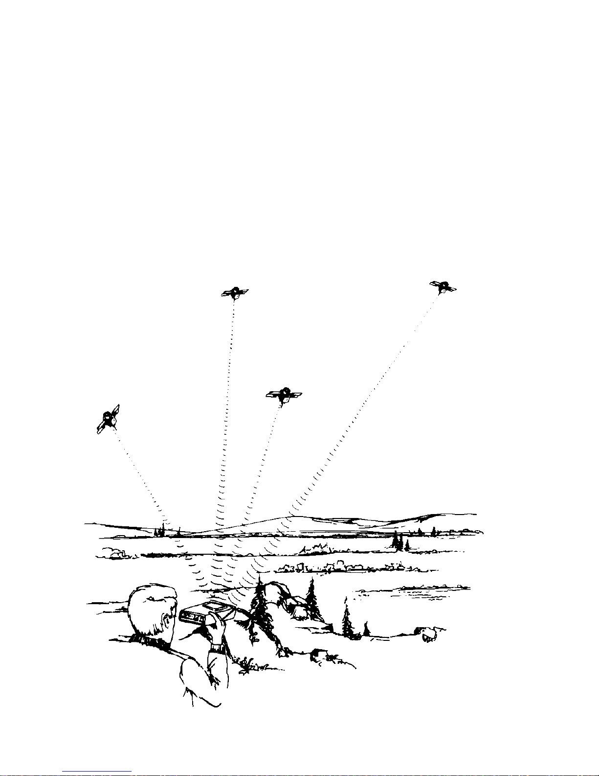
GPS is a satellite-based radio navigation system. The system ul-
timately will be a constellation of 21 active satellites and 3 spares
in orbits around the earth. This configuration will ensure worldwide operation with 24-hour, all-weather coverage. Each satellite transmits data that enables GPS receivers to provide precise
position and time.
NOTE
Until the constellation is complete, coverage may be
limited
to specific hours of each day in certain areas of
the world.
TRANSPAK
The
TRANSPAK
GPS Personal Navigator is a hand-held, batterypowered navigation set that receives data from GPS satellites and
calculates and displays position, velocity, time, and navigational
data in any one of three operational modes: land, sea, and air.
Three-dimensional fixes are obtained when tracking 4 or more
satellites; 2-dimensional fixes can be obtained from 3 satellites
plus user-entered altitude.
The
TRANSPAK
receiver requires line-of-sight access to the satellite signals. Hold the unit level, with its intemal antenna facing
toward the sky. GPS navigation signals are similar to light, so
anything that blocks light will block or reduce the
effectiveness
of the signals. The more unobstructed view of the
sky you have,
the better your
TRANSPAK
will perform. Avoid
placing your hands
an or over the antenna when the
TRANSPAK
is in operation.
Page 10
2
CONTROLS and INDICATORS
Page 11

3
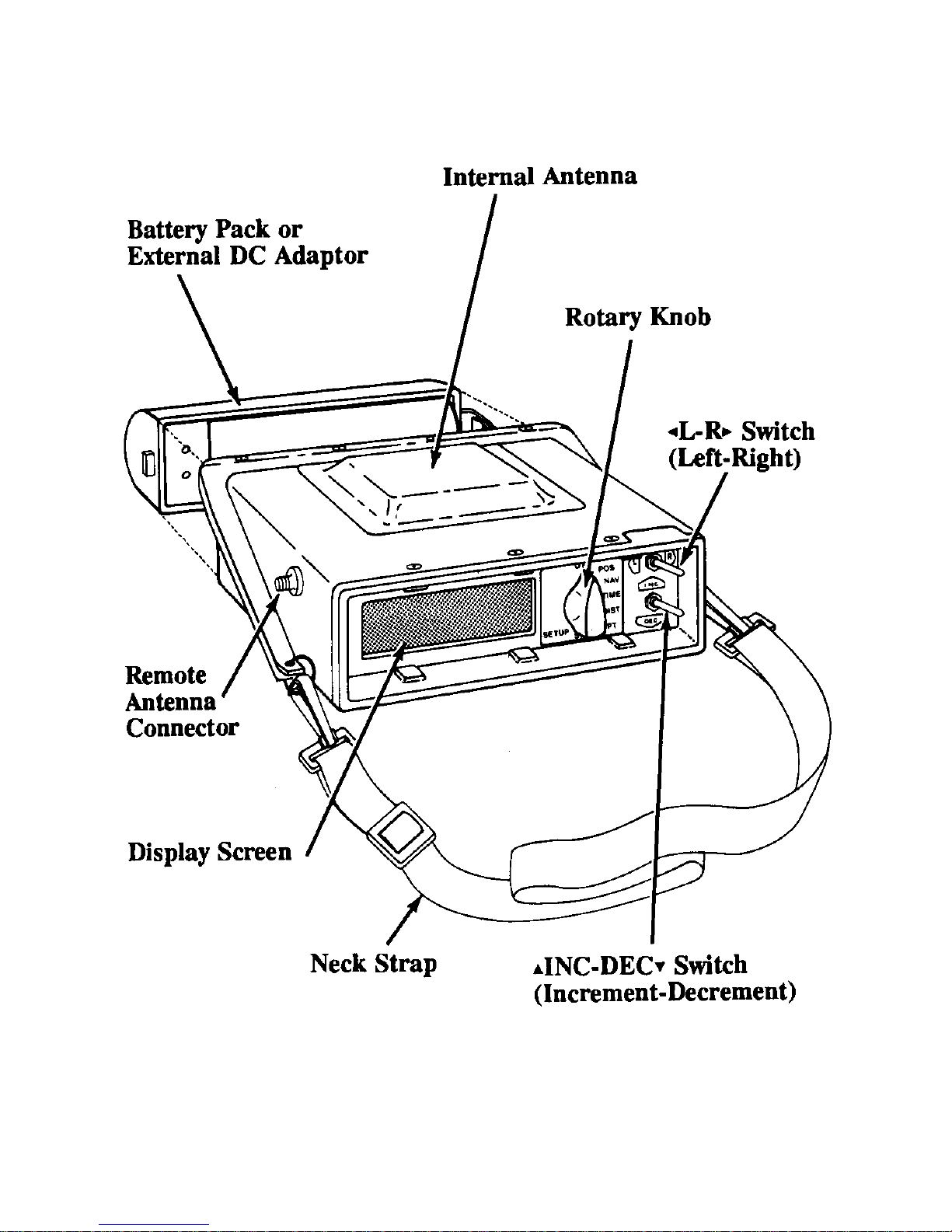
Display Screen
The
TRANSPAK
displays information on the backfit 4-line LCD
screen. The screen contents are determined by the rotary knob
and user-selected options.
Rotary Knob
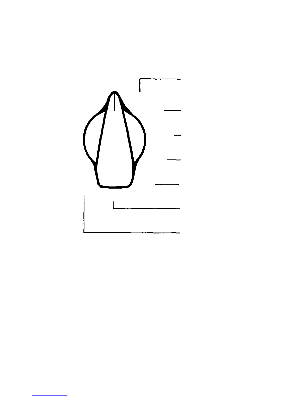
This 8-position switch selects the type of operation that the
TRANSPACK
will perform—for example: "POS" (positioning) op-
erations.
t
L
-
Ru (Left-Right) Switch
This 2-way switch is used to select items on the screen (indicated
by a flashing box). Momentarily pressing the switch to the left
or right selects different screen items.
pINC
-
DECq (Increment/Decrement) Switch
This 2-way switch is used to walk through numbers, letters of the
alphabet, or options (as on a list). Momentarily pressing the
switch upward or downward changes the value of the selected
item on the screen.
The pINC-DECq switch is also used as a trigger when
the
selected screen item represents an action to be performed
(indi
cated by brackets: <action>).
Both switches automatically repeat at a rapid rate when held on.
This feature can be used to quickly roll up to high numbers or to
scan past many screen items to select one farther on.
Low Battery
A battery symbol will blink in the
lower right corner of
thescreen in all knob positions to indicate a low battery
condi
tion. The
TRANSPAK
should be powered down and the
batteries
replaced or recharged when this symbol appears.
CONTROLS and INDICATORS
Page 12

Refer to Section 3,
Maintenance
(page 40), for procedures to
remove or install battery packs, recharge the nickel-cadmium
battery pack, and replace batteries in the alkaline battery pack.
External DC Adaptor
This adaptor enables the
TRANSPAK
to be powered by an external,
9- to 32-volt, 5-watt DC supply, such as a cigarette lighter outlet
in your vehicle.
Refer to Section 3,
Maintenance
(page 40), for procedures to
remove or install the adaptor.
4
OTHER PARTS AND ACCESSORIES
Battery Packs
Two types of battery packs are currently available to support
specific user requirements.
Standard:
Non-rechargable alkaline battery pack.
This pack holds
eight AA batteries and provides over 3-1/2 hours of continuous operation.
Optional:
Rechargable nickel-cadmium battery pack.
This pack
also provides over 5 hours of continuous operation; it can
be recharged in about 16 hours.
Page 13

5
OTHER PARTS and ACCESSORIES
Increased Storage Option
The standard
TRANSPAK
can store up to 99 waypoint descriptions
in its internal memory. An optional configuration is available
that will store up to 999 waypoint descriptions.
External Antenna Option
An optional external antenna with mounting hardware and
cable
is available for stationary mounting of the receiver
antenna up to
50 feet (15 meters) from the TRANSPAK. The
external antenna can
be mounted to provide unobstructed
satellite coverage if the
TRANSPAK
must be operated indoors or
in a vehicle. When not in
use, the antenna connector dust cover
should be installed to keep
the connector clean.
Other Items
•
The camera-type neckstrap can be attached by clipping it to
the rings on both sides of the
TRANSPAK.
•
Optional vehicle mounting brackets are available for the
TRANSPAK.
Page 14
North Latitude
Equator
South Latitude
South Pole
Longitude East
Longitude West
Greenwich
Meridian
North Pole
Typical POS screen; LAT and LON in DM. format.
COORDINATE SYSTEM
6
Page 15

7
COORDINATE SYSTEM
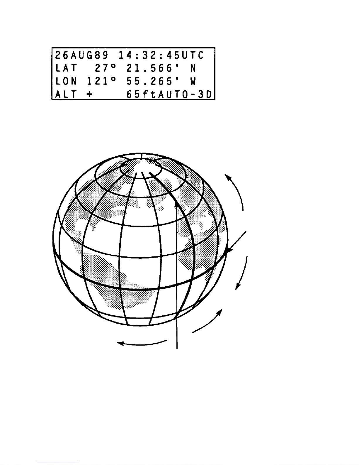
The
TRANSPAK
displays position information in the Degree,
Minutes, Decimal Minutes (DM.) coordinate system. This is a
latitude/longitude-based system, with position expressed in
degrees and minutes. Minutes are displayed to one-thousandth
of
a minute in decimal form.
Page 16
SETUP
POS
Position Mode
OFF
NAV
Navigation Mode
TIME
Time Mode
DIST
Distance Mode
WPT
Waypoint Mode
Setup Mode
STS
Status Display
ROTARY KNOB POSITIONS
8
Page 17

NAV:
TIME:
DIST:
WPT:
STS:
SETUP:
The
TRANSPAK
powers down after a 15-second delay
Displays time, date, latitude, longitude, altitude, and
mode of operation.
Provides navigation data to a selected destination
waypoint.
Displays time, date, and time enroute information.
Displays the distance and bearing between any two
waypoints.
Edit, define, or clear up to 999 waypoints.
Provides operating status information.
Allows selection of display options.
9
Safety Information
Be sure to read the important safety information on the inside rear
cover before operating the
TRANSPAK.
ROTARY KNOB POSITIONS
To select the type of operation that the
TRANSPAK
will perform,
rotate the knob to:
OFF:
POS:
Page 18
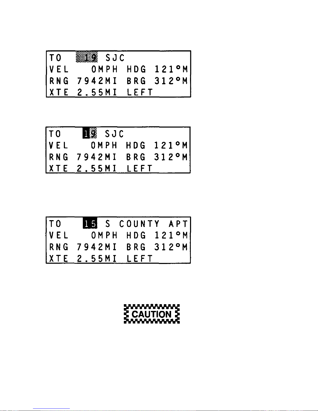
HOW TO CHANGE DATA
Typical Screens
10
Waypoint units digit selected by initial pINC-DEC q
switch toggle.
Waypoint digit modified by subsequent pINC-DECq
switch toggles.
Waypoint number selected by t L-R u switch.
The
tL-Ru
switch only selects screen items; it does not
affect their values. However,
pINC-DECq
alters the
value of the selected item. Before using
pINC-DECq
,
make
sure the correct item is selected.
Page 19

11
HOW TO CHANGE DATA
Most screens contain some user-alterable items. These may
include numbers, letters, or options that can be changed, or
"triggers" that cause an action. In this manual' s example screens,
the alterable items are shown in reverse type.
On the screen, a flashing box indicates the selected item. The box
is represented by a gray shading in the example screens. Use the
tL-Ru
switch to select a different item. Pressing the switch once
to the right selects the next screen item; left selects the previous
item. At the last item, the next selection returns to the first item
on the screen.
Using
pINC-DECq
alters the value of the item or triggers the
action. Pressing the switch upward once changes the value of the
selected item on the screen to the next level; downward changes
to the next lower value. At the highest value, the next step returns
to the lowest value.
For example, to change the waypoint identifier from 19 to 15 in
the TO line of the top screen (opposite page), use the
tL-Ru
switch to move the flashing box to the waypoint number (19 on
second screen). Press the
pINC-DECq
switch once to open
the
item for modification; the digit 9 will flash. Then press the
pINC-DECq
switch down four times to change the value to 5
(third
screen).
Safety Timer
If no switches are pressed for 25 seconds, the selected item stops
flashing and
pINC-DECq
has no effect, thus preventing
acciden
tal changes. After this occurs, the
tL-Ru
switch must
be used
to once again select an item to be changed.
Page 20
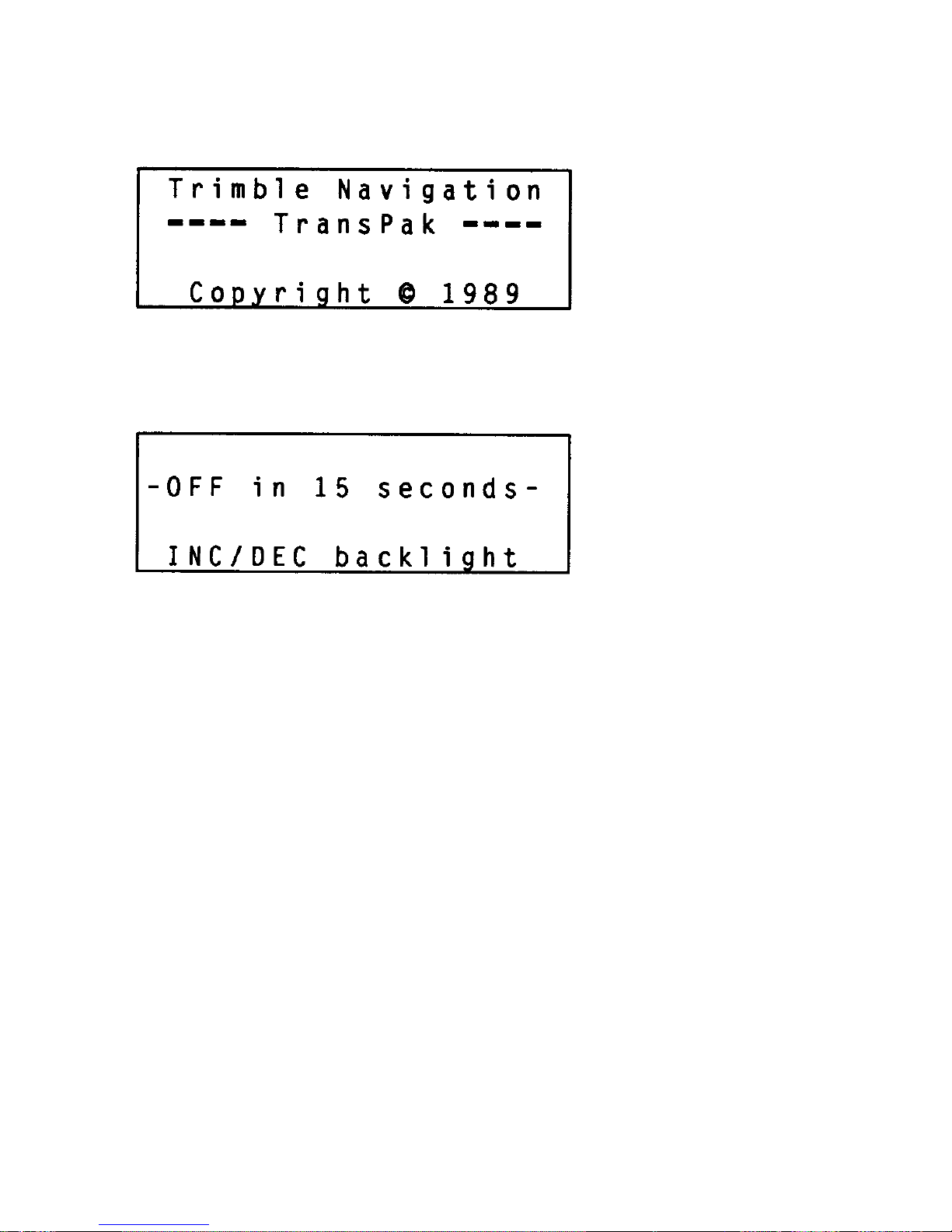
Turn-Off
12
TURN ON/OFF
Turn-On
Page 21

13
Turn-On
Turn the
TRANSPAK
on by tuming the rotary knob to any one of the
operating positions. A brief sign-on message is displayed, while
the
TRANSPAK
performs a self-test. No switches are active during
this time. When the power-on sequence is completed, the rotary
knob position determines the type of operation.
Turn-Off
When you turn the rotary knob to OFF, the screen displays a 15second countdown before power is turned off. During the countdown, you can return the
TRANSPAK
to full operation instantly by
turning the rotary knob to another position.
Backlight Control
Pressing
pINC-DECq
during the turn-off countdown varies
the
screen backlight level. The backlight is off when the
TRANSPAK
is first turned on. Increasing the backlight level
increases battery
wear.
TURN ON/OFF
Page 22
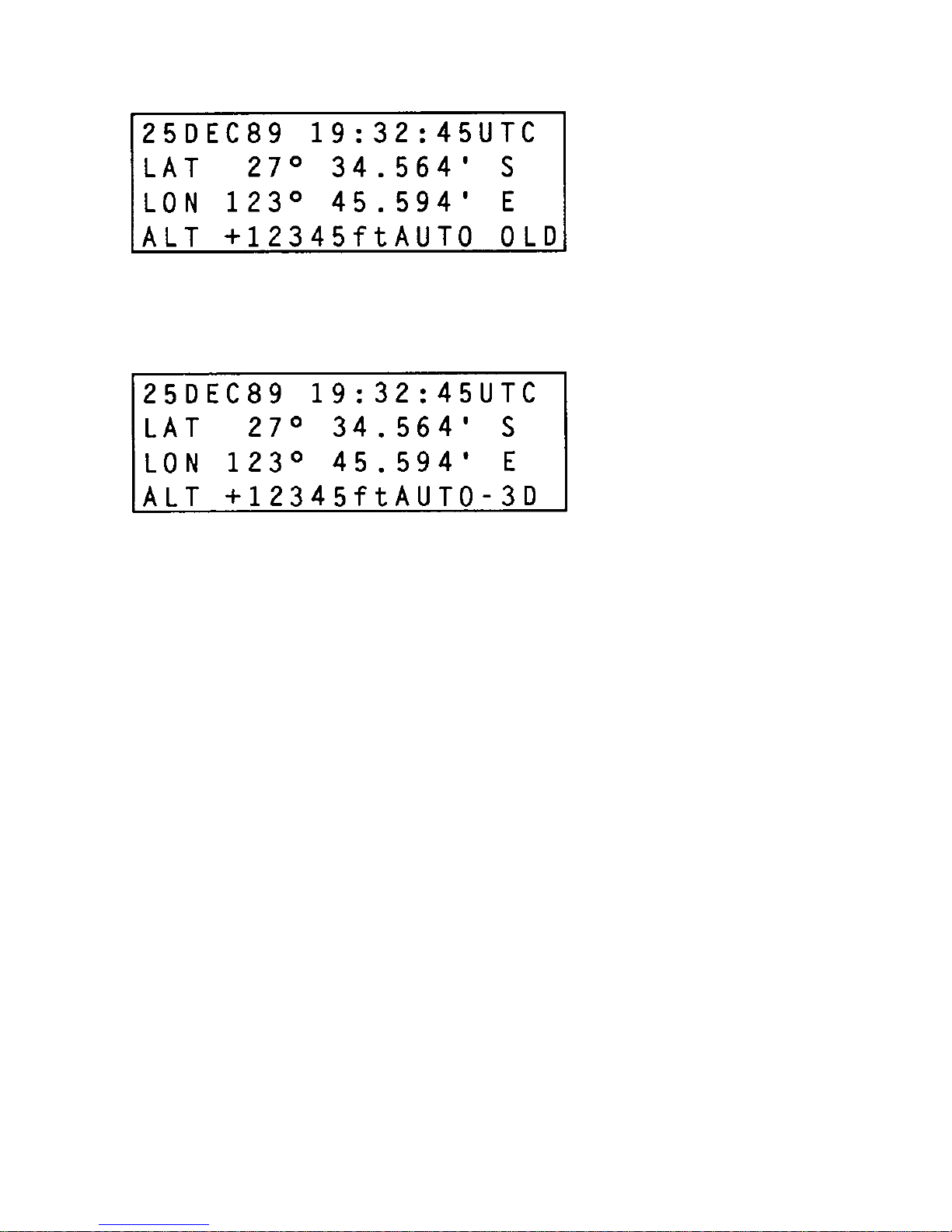
Typical POS screen after the
TRANSPAK
is powered on but does not
have a fix.
The
TRANSPAK
has locked onto four SVs and is getting position
fixes.
14
GETTING STARTED: YOUR FIRST GPS FIX
Page 23

15
GETTING STARTED: YOUR FIRST GPS FIX
To turn the
TRANSPAK
on, rotate the knob from the OFF position
to the POS position. Your
TRANSPAK
was initialized at the factory
with the date, time, and the location of Trimble Navigation.
Initially, the POS screen will display the current date and time, and
the LAT, LON, and ALT for Trimble Navigation. Once the
TRANSPAK
locks onto three SVs, the LAT, LON, and ALT fields
are updated to reflect your position.
The operating mode is displayed in the lower right corner of the
screen. OLD indicates that the
TRANSPAK
is not performing
position fixes. This is to be expected when die
TRANSPAK
is first
powered on.
Your
TRANSPAK
can provide a fix in as little as 1 second, assuming
that at least three SVs are "visible" to it. However, it may take as
long as 5 minutes to get that first fix if the unit has been moved
thousands of miles while powered off. You can expect to get
your first position fix within 5 minutes with subsequent fixes at
1-second intervals. Refer to
Troubleshooting The
TRANSPAK
(page
44) if you are not getting fixes after 5 minutes of operation.
The screens on the opposite page are typical for the POS
position.
Page 24
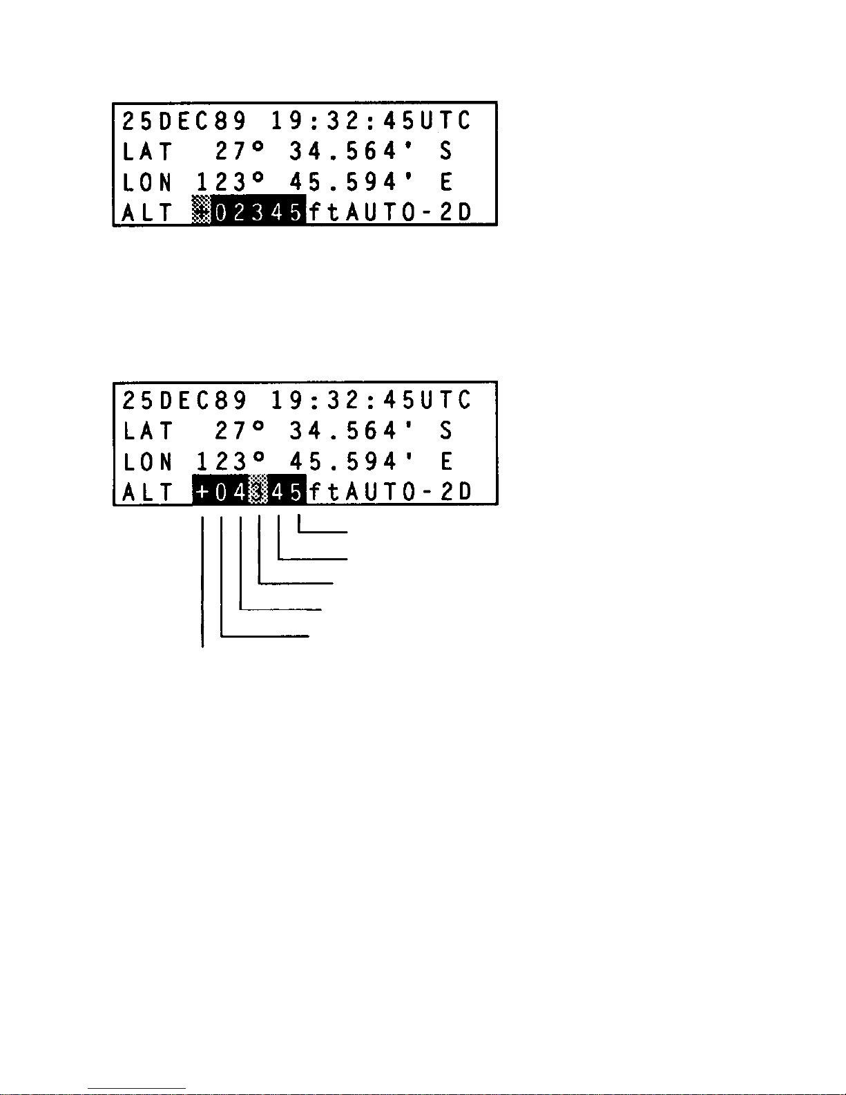
Altitude can be modified when AUTO is selected in the
SETUP
position and the
TRANSPAK
drops into 2D operation.
A blinking
ALT field must be updated.
Altitude Entry Example
±
Example:
To set altitude to 4345 feet:
•
move to ± position and toggle to +
•
move to 10,000 position
•
if it already contains a value, set it to 0
•
if it is already at 0, ignore it
•
move to 1,000 position and set it to 4
•
move to 100 position and set it to 3
•
move to 10 position and set it to 4
•
move to 1 position and set it to 5
1
10
100
1000
10000
POS
16
Page 25

17
POS
Position information is displayed when the rotary knob is set to
POS. If position fixes are not being performed (as when the
TRANSPAK
is first turned on), the word OLD will appear in the
lower right corner of the display, indicating that the position is
old.
Line 1 of the display shows the date and the time (a 24-hour clock
is used) in either UTC, GMT (or Zulu), or local time. Local time
is not labeled. Lines 2 and 3 show the position coordinates in
degrees and minutes. Line 4 shows the altitude in either meters
or feet and the mode of operation of the
TRANSPAK
(AUTO, 3D or
2D).
Entering Altitude
If the
TRANSPAK
is providing 2D fixes, you must manually enter
an altitude. The altitude contains a 5-digit number preceded by
a sign to indicate above (+) or below (-) sea level. Select the item
by using the
tL-Ru
switch.
Change to the proper sign by pressing the
pINC
switch, then use
the
Ru
switch to move to the first non-zero digit and toggle in
the desired value. If the remaining digits are zeroes, you are done;
if other values are required, continue with the
Ru
and
pINC
switches until all non-zero values are displayed.
Only altitudes between -500m (-600ft) and +20000m (65000ft
are allowed.
Altitude also can be entered in the
SETUP
Position.
Page 26

18
POS
Auto/2D/3D Operation
The
TRANSPAK
provides either 3D or 2D fixes. In AUTO mode,
TRANSPAK
uses signals from 4 SVs to provide position fixes in 3
dimensions including altitude. If only 3 SVs are available, 3D
fixes are not possible; the
TRANSPAK
then performs 2D fixes (no
altitude). The
TRANSPAK
uses the last altitude either calculated by
a 3D fix or entered by the user.
The accuracy of the 2D fix
depends on the accuracy of the estimated altitude.
The
lower
right corner of the screen shows either AUTO-3D or
AUTO-2D
if the
TRANSPAK
is performing position fixes, or
AUTO-OLD if no
fixes are being made.
If the
TRANSPAK
is in AUTO mode and has been receiving signals
from 4 SVs and loses contact with one of them, it switches from
3D to 2D operation. If you do not enter a new altitude value
within 30 minutes, or if you move more than 1 mile from the
position of the last 3D fix, the altitude field flashes, indicating
that you should enter a new altitude. When 3D fixes resume, the
TRANSPAK
resumes display of the GPS-calculated altitude.
Your
TRANSPAK
typically is accurate to within 25 meters horizontally. Selective availability, a Department of Defense program
to deny full GPS accuracy to unauthorized users, deliberately
corrupts the GPS satellites' radio signals. When obtaining a 3dimension position fix, vertical (altitude) errors are 2 to 3 times
worse than the horizontal errors (e.g., if your longitude is off by
25 meters, your altitude may be off by 50 meters).
Page 27

Manual 2D/3D Operation
Manual 2D
Manual 2D operation is intended for boating and other applica-
tions in which the altitude is not of concern. It provides for
entering a fixed altitude once and having the
TRANSPAK
perform
2D fixes without the need to update the altitude.
NOTE
It is vitally important that the altitude entered in
manual 2D operation be correct to obtain accurate 2D
fixes.
NOTE
Manual 2D/3D Operation is selected in the SETUP
position.
The best way to ensure a correct altitude is to take a series of
AUTO-3D fixes and use the GPS-calculated altitude when running in manual 2D.
Manual 3D
This mode is intended for the aviator and applications where
an estimate of altitude is just not good enough. Manual 3D
operation provides for 3D fixes only. When 3D fixes are no
longer possible,
TRANSPAK
will blink OLD until 3D fixes
resume.
POS
19
Page 28
(Screen shown in Land mode)
20
NAV
Page 29

21
NAV
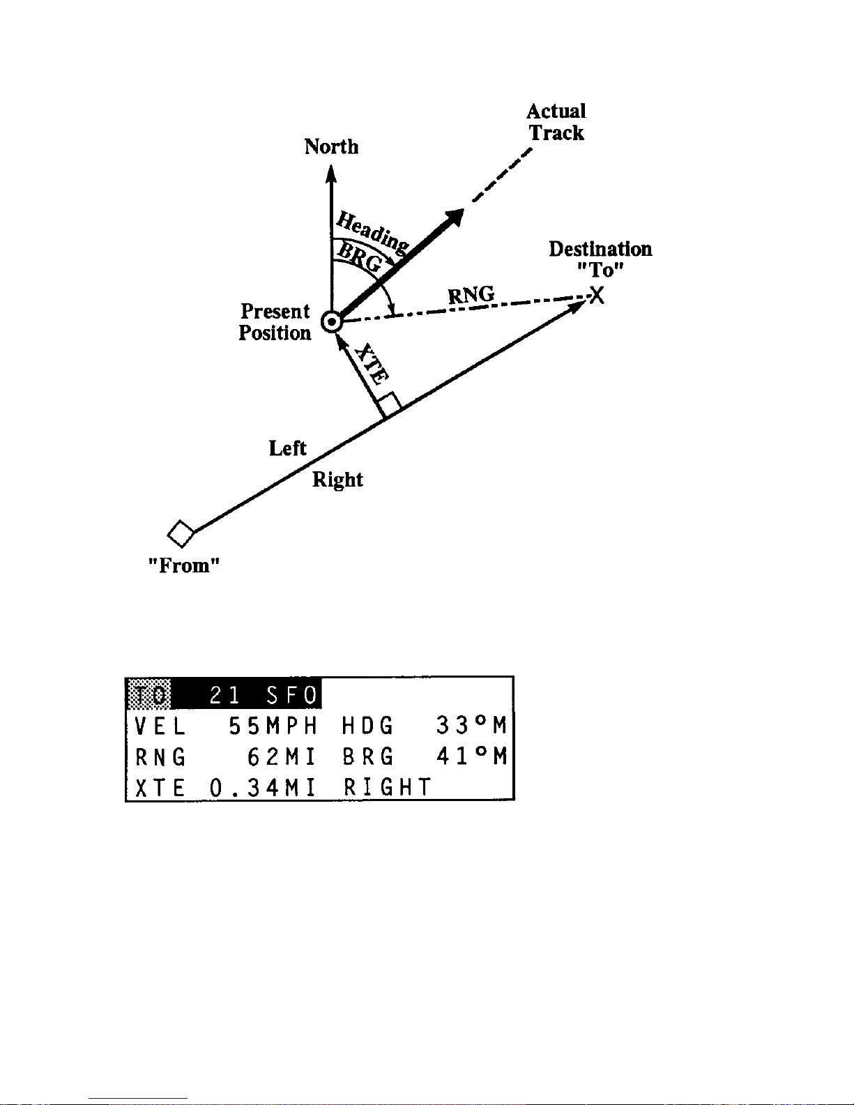
The NAV knob position displays data to help you navigate from
your present position to another position. In the NAV position,
the
TRANSPAK
presents the Land, Sea, or Air screen format
selected in the SETUP position.
A typical Land screen is shown on the opposite page. The NAV
screen uses two waypoints to establish the great circle course
between them. The NAV screen displays your velocity and
heading, the range and bearing to the TO waypoint, and your
distance (XTE) from the optimal course between the FRM waypoint and the TO waypoint. The TO field can be toggled between
TO and FRM using the
pINC-DECq
switch to display the TO
and
FRM waypoints, respectively. Another TO or FRM
waypoint
can be selected from the waypoint library by
modifying either the
waypoint number or the waypoint label.
For example, to change the TO waypoint from 0 to 1, press the
tL-Ru
switch one time to the right. The waypoint number field
will blink. Press the
pINC-DECq
switch once to open the
number field for modification; press it a second time to change
the 0 to a 1. Whenever the TO waypoint is changed, the FRM
waypoint is reset to your present position, thus defining an
optimal course from where you are now to the TO waypoint.
Navigating with TRANSPAK
The figure on the opposite page shows how the present position
is used to derive the range (RNG) and bearing (BRG) to the
destination and how the velocity is used to find the heading
(HDG). When a FRM waypoint is specified, the cross-track error
(XTE) is calculated as the perpendicular distance from the unit's
position to the straight line track between the source and destination.
Page 30
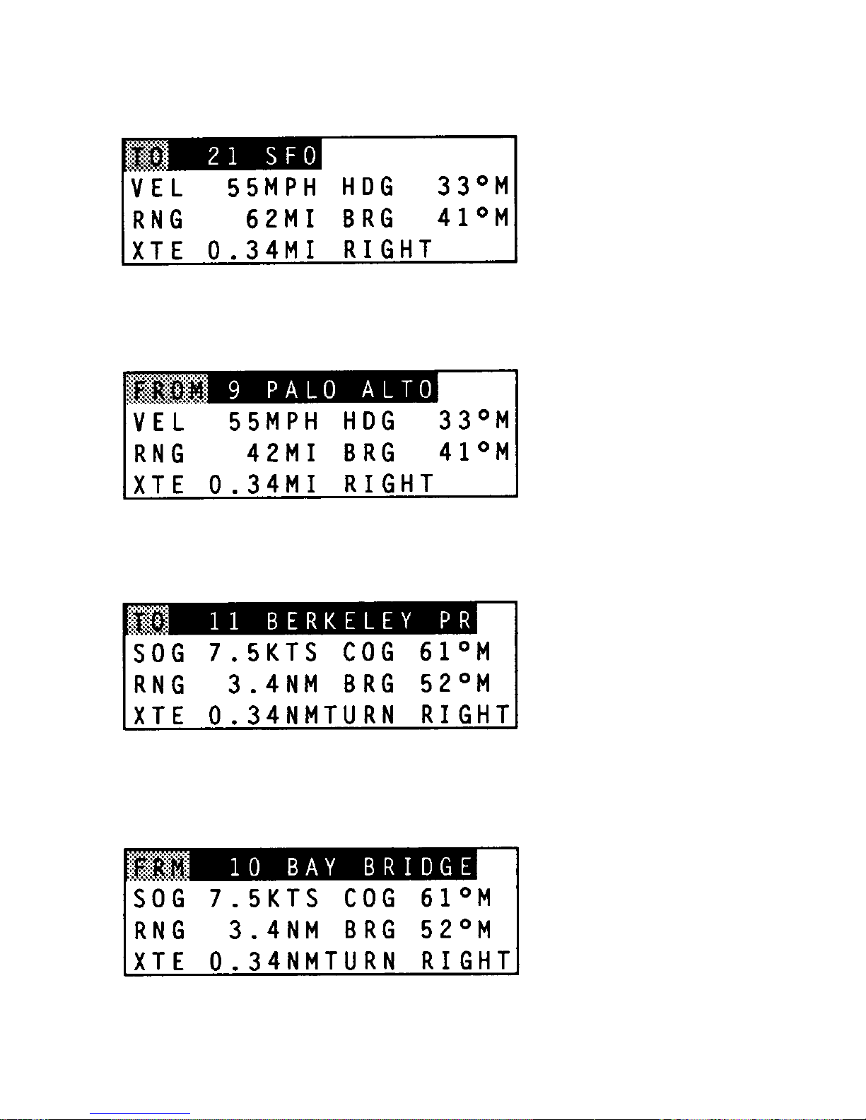
The
t L-R u
key selects the TO field.The
pINC-DEC q
key
toggles
between the TO and FRM waypoints.
The
t L-R u
key selects die TO field. The
pINC-DEC q
key
toggles
between the TO and FRM waypoints.
Sea Mode
22
NAV
Land Mode
Page 31

23
NAV
LAND Mode
This display provides the information required when you are
traveling to your destination on foot or by car. Velocity,
heading,
range, bearing, crosstrack error, and direction are
displayed.
Right crosstrack error indicates that the track
between the FRM
and TO waypoints is to your right.
SEA Mode
This display provides the information required when you are at
sea. Speed over ground, course over ground, range and bearing,
crosstrack error, and direction are displayed. The crosstrack error
tells you which way to turn to reduce the crosstrack error.
Page 32
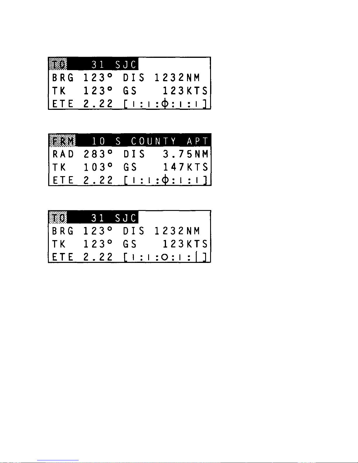
Turn right; 2 NM left of course.
24
NAV
Air Mode
Page 33

25
NAV
AIR MODE
This display provides the information required when flying to a
waypoint. Bearing, distance, track, ground speed, estimated
time enroute, and a course deviation indicator (CDI) are displayed. The CDI is calibrated to
1
unit (kilometer, statute mile,
or nautical mile) of crosstrack error between vertical bars on the
CDI. To reduce the crosstrack error, turn in the direction of the
blinking vertical bar on the CDI.
In all three modes (Land/Sea/Air), if the
TRANSPAK
is not doing
position fixes, the numbers displayed in VEL, RNG, BRG, etc.
are replaced by asterisks. The units of measure for the display
fields are selected by the METRIC/ENGLISH/NAUTICAL
field of SETUP.
In the AIR mode, when the TO field is toggled to FRM, the BRG
field changes to RAD and displays the radial from the displayed
waypoint. The DIS field also displays the distance from the
displayed waypoint. This is useful when you are flying away
from a VOR.
Page 34
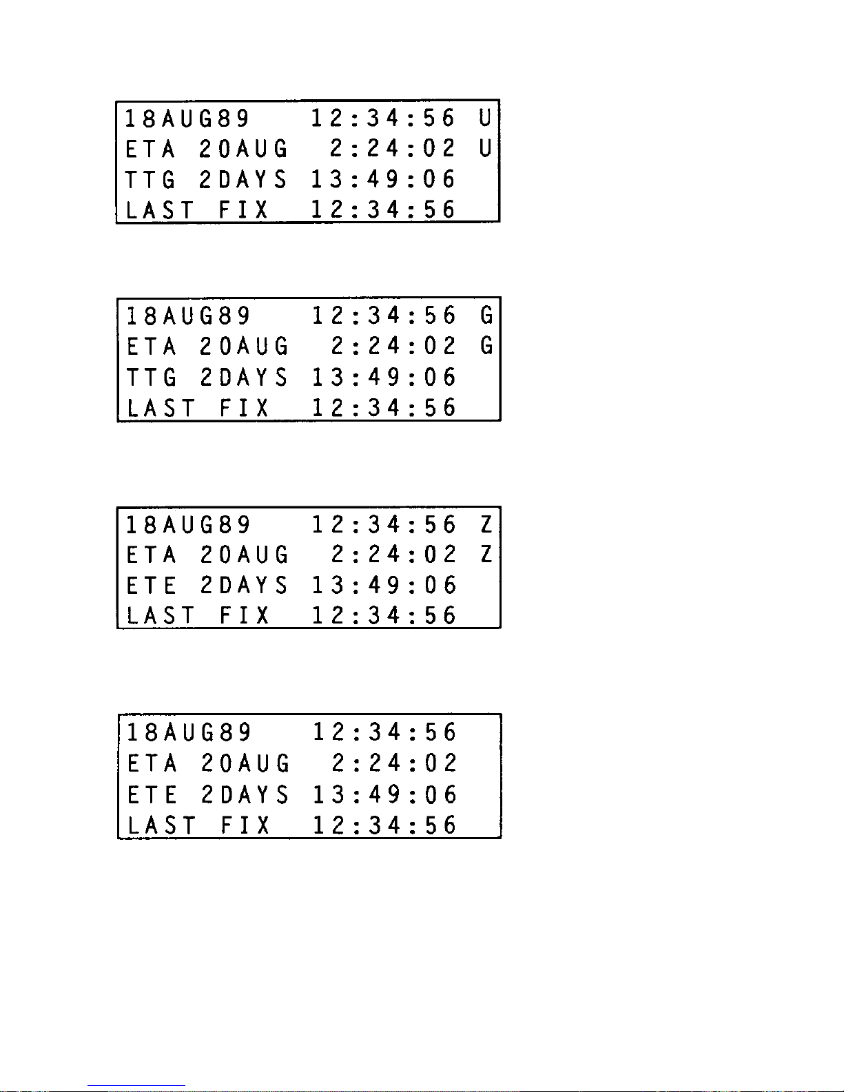
Land mode; local time offset is zero.
Sea mode; local time offset is zero.
Air mode; local time offset is zero.
All modes with a local time offset.
26
TIME
Page 35

27
TIME
The TIME knob position displays the date and time (24 hours,
UTC or local), the estimated time of arrival (ETA), the time to go
(TTG), and the time of the last fix (LAST FIX). Date of arrival
is not indicated. In AIR mode, estimated time enroute (ETE)
is
displayed rather than TTG.
The time of arrival and time to go are based on data entered in the
NAV knob position. If the TO waypoint on the NAV screen is
changed, ETA and TTG/ETE change accordingly.
The ETA and TTG/ETE fields are filled with asterisks if the
TRANSPAK
is not performing position fixes, or if you are moving
away from the TO waypoint.
Page 36
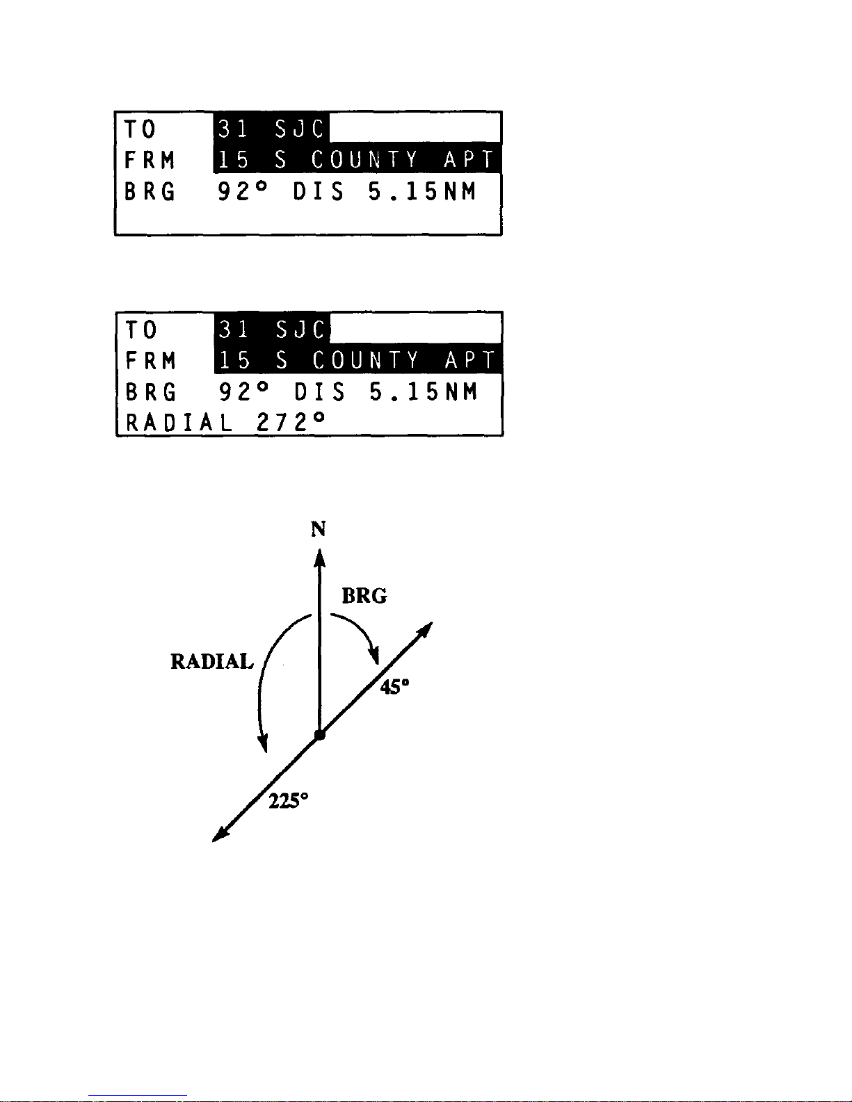
28
DIST
The distance screen in Land and Sea modes.
The distance screen in Air mode.
Page 37

29
DIST
The DIST knob position calculates the range and bearing be-
tween any two waypoints, using a great circle route. The TO
and FRM waypoints are selected by modifying either the
wayoint numbers or waypoint labels to find the desired
waypoints. It is not possible to modify the contents of a
waypoint from the DIST knob position. The distance units
(Km/MI/NM) and the bearing (T/M) are selected by the
SETUP field (METRIC/ENGLISH/NAUTICAL) and (TR/
MG).
The radial to the FRM waypoint is supplied in the Air mode.
Page 38

The Waypoint screen.
The initial Edit Waypoint subscreen.
Copying waypoint 12 into waypoint 13.
30
WPT
Page 39

31
WPT
The WPT (Waypoint) knob position enables you to display, edit,
and clear up to 99 waypoints (999 in optional configuration). Rotating the knob to WPT displays the waypoint selection screen.
You can search for a waypoint, or enter one of the modes defined
by the triggers (<FIX>, <EDT>, <R/B>, <CLR>) on the bottom
of the display. You cannot modify or erase waypoints from the
initial waypoint screen.
You may select a waypoint from the waypoint library by number,
by label, or by alphabetic search.
Selecting a Waypoint by Number
To select a waypoint by number, press the
tL-Ru
switch until
the
waypoint numeric field is highlighted. Then press the
pINC-DECq
switch to open the numeric field for
modification and use
the
pINC-DECq
switch to modify the
number. Once the field has
been opened for modification, use
the
tL-Ru
switch to move
between the units, tens, and
hundreds digits.
Page 40

32
WPT
Selecting a Waypoint by Label
To select a waypoint by label, use the
tL-Ru
switch to high-
light the waypoint label field. Press the
pINC-DECq
switch
once to open the field for modification. Then use the
pINC-DECq
switch to select characters within the label field
and the
pINC-DECq
switch to alter the selected characters.
When the
pINC-DECq
switch is pressed, the highlighted
character is modified to either the next or prior character and the
waypoint library is searched for a match on the character string
to the left of and including the modified character. If no match
is found, the character is incremented or decremented again and
another search is performed. If a next higher/lower label is found
in the waypoint library, it is displayed. If the character string to
the left of the selected character is unique, the label field will not
change.
Selecting a Waypoint by Alphabetic Search
The alphabetic search field is located between the numeric field
and the label field. When the alphabetic search field is
selected
using the
tL-Ru
switch, a character is displayed in
the space
between the numeric field and the waypoint label.
Pressing the
pINC-DECq
switch up displays the next
alphabetic waypoint
label; pressing it down displays the prior
alphabetic waypoint.
This provides a quick method of
scanning the waypoint library.
Page 41

33
WPT
Triggers
The <FIX> trigger stores the current fix into the next empty waypoint. The search for an empty waypoint begins with the
displayed waypoint and is stored in that waypoint if it is empty.
After the fix is stored, the waypoint into which the fix was
deposited is displayed. The waypoint label field is filled either
with the time if the fix was current or with the designator
OLDFIX if the fix was old. You can edit the waypoint to rename
the time. Time is stored as hours minutes seconds in six digits.
The <EDT> trigger opens the currently selected waypoint for
modification. The waypoint number can be modified, which will
copy the waypoint data into a new waypoint (copy a
waypoint).
The waypoint label field can be modified by
moving into the
label field and using the
pINC-DECq
keys
to scroll through the
alphabet and numbers. The LAT and LON
fields can be modified
by selecting the field to alter and using
the
pINC-DECq
switch
to scroll the numeric field. The newly
altered waypoint is saved
by selecting the <YES> field and
pressing
pINC-DECq
in either
direction. The edits can be
discarded and the waypoints left un
changed by selecting the
<NO> field and pressing the
pINC-DECq
switch.
Page 42
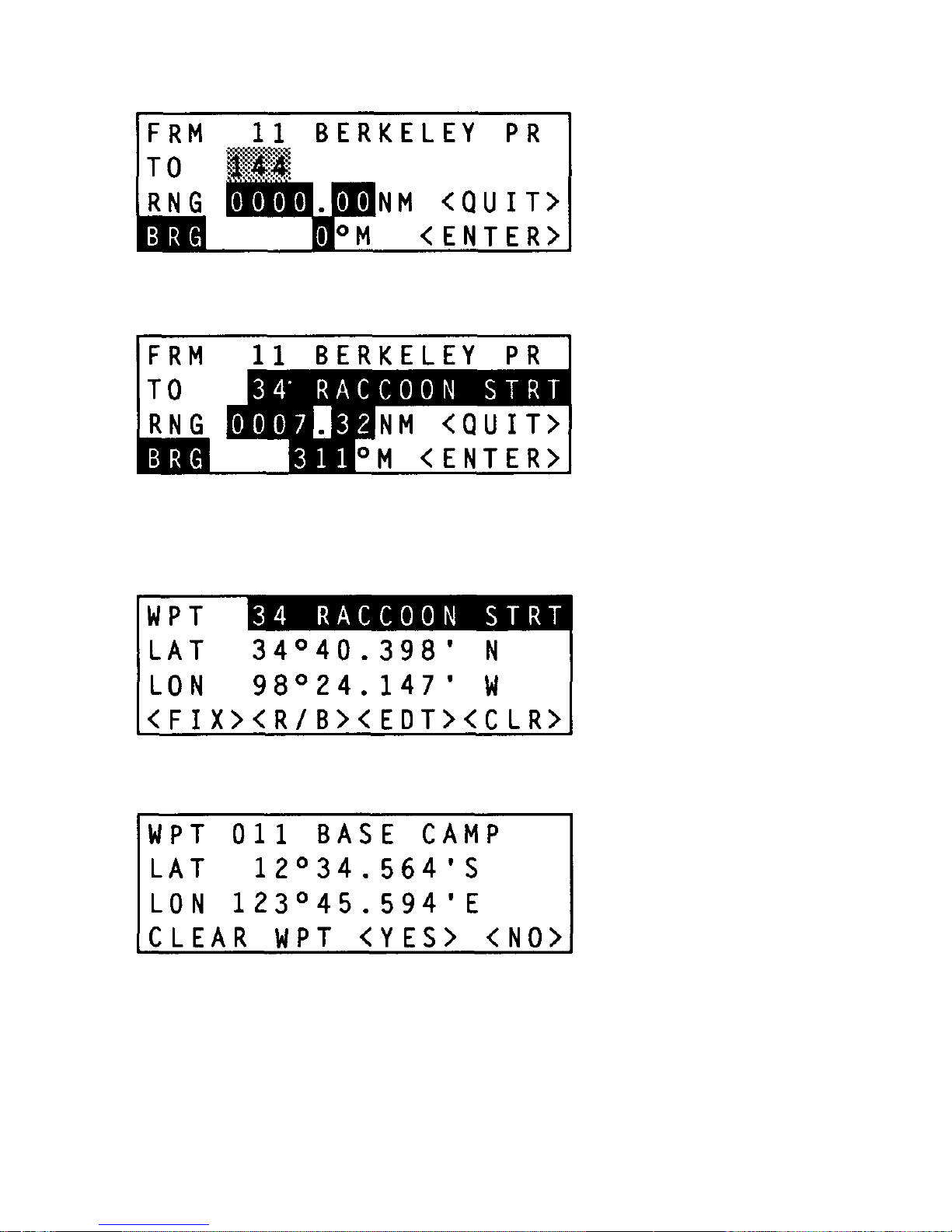
Waypoint 12, Raccoon Strt., has been created.
Clear Waypoint subscreen.
34
WPT
The initial Range/Bearing subscreen.
The Range/Bearing subscreen just prior to creating the Raccoon
Strt. waypoint.
Page 43

35
WPT
The <R/B> trigger defines a second waypoint with a range
and
bearing offset from the selected waypoint. The R/B
screen
displays the selected waypoint on the first line. The
second line
displays the number of the next empty waypoint.
The waypoint
number and the label field can be modified to
name the new
waypoint and to deposit it into any waypoint
number. Modify the
range and bearing to define the new
waypoint.
The <ENTER> trigger stores the new waypoint and returns to the
waypoint screen with the LAT/LON of the new waypoint displayed.
The <QUIT> trigger returns to the waypoint screen with no
modifications made to the waypoints. Note that the distance
units of the range are selected by the METRIC/ENGLISH/
NAUTICAL field of SETUP and that the bearing units are either
magnetic (M) or true (T), based on die MG/TR field in SETUP.
The <CLR> trigger is used to clear a waypoint. You can clear the
selected waypoint by moving the blinking cursor to the <CLR>
trigger with the
tL-Ru
switch and pressing the
pINC-
DECq
switch in either direction. The currently selected
waypoint is
displayed with the prompt
CLEAR
WAYPOINT <YES>
<NO>; <YES> is highlighted.
Pressing the
pINC-DECq
switch
clears the waypoint and the
next sequential waypoint is dis
played. A range of waypoints
is cleared by pressing the
pINC-DECq
switch a number of
times. To return to the Waypoint
screen, select the <NO>
field using the
tL-Ru
switch and press
the
pINC-DECq
switch.
In the Air mode, the BRG field can be toggled between BRG and
RAD to enter either a bearing to or a radial from a waypoint.
Page 44
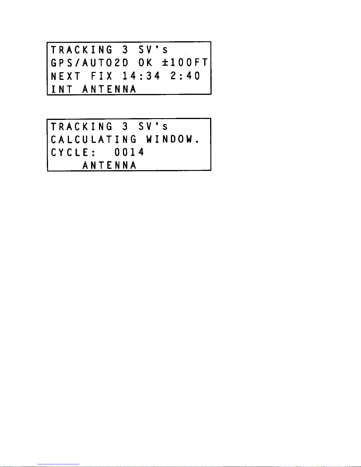
STS
36
Page 45

37
STS
The STS knob position displays the status of
TRANSPAK.
Line 1
presents the number of satellites that the
TRANSPAK is
tracking.
Four SVs are required for 3D fixes. Three SVs are
required for
2D fixes.
Line 2 presents the current state of the GPS receiver: OK
indicates the
TRANSPAK
is making position fixes; N/A indicates
that insufficient satellites are visible to make a fix; BAD indicates either that sufficient SVs are available but they are positioned such that a fix is not possible or that a receiver error has
occurred; see page 44. The estimated accuracy of the fix is
displayed if the
TRANSPAK
is making position fixes.
Line 3 indicates the window of satellite availability. 24-hour
GPS coverage will be possible when the full complement of
satellites has been launched. Until that time, there will be
windows of GPS availability. If you are presently within a
window of availability (sufficient SVs are visible), line 3 presents the amount of time remaining in the current GPS window
and the start of the next window (REM 1:30 NEXT 14:14). If you
are not now within such a window, line 3 shows the starting time
of the next window and its duration (NEXT FIX 18:45 6:20).
Time is displayed as local or UTC, as selected in the SETUP
position.
Line 4 lists the operable antenna (INT or EXT for the internal or
external antenna, respectively).
Page 46
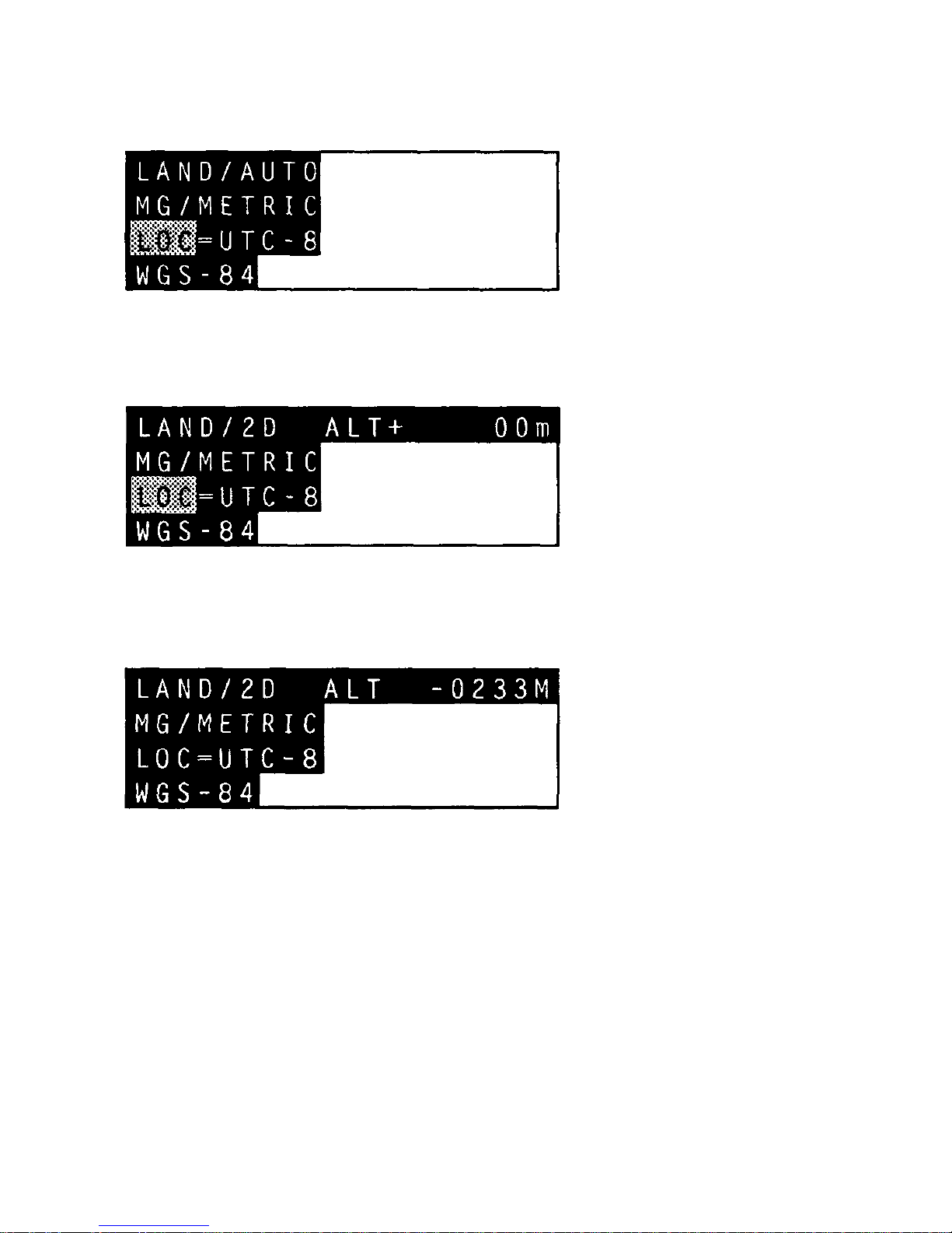
Setup screen: Land mode, AUTO 2D/3D, magnetic heading,
metric units of distance, local time, WGS-84 datum.
Setup screen: Land mode, 2D, ALT = 00, magnetic heading,
metric units of distance, local time, WGS-84 datum.
The Setup screen.
38
SETUP
SETUP
Page 47

39
SETUP
The SETUP knob position displays the current display options.
Each of the SETUP fields can be modified.
Time can be displayed in UTC, GMT, Zulu, or 24-hour local
time. When in the SETUP position, to adjust
TRANSPAK
time to
local time, use the
tL-Ru
switch to move the blinking cursor to
the UTC field. Use the
pINC-DECq
switch to set the local ti-
me
offset from UTC time. When you return to another
position of
the rotary knob, the correct local time will be
displayed.
The LAND/SEA/AIR field tailors the
TRANSPAK
for land, sea, or
air operation. The AUTO/2D/3D selects the type of fix provided
by the
TRANSPAK.
For a more detailed description of AUTO/2D/
3D, see the POS section (pages 18 and 19). MGR/TR
selects
either magnetic or true north for all heading
information.
NAUTICAL/METRIC/ENGLISH selects the
distance units.
The last field selects the datum for LAT/LON display. All maps
have a reference earth model, or datum, relative to which the
in
formation on the map is accurate. By selecting a datum,
you
select a LAT/LON correction which is applied to all LAT/
LON
displays. The correction is the difference between the
GPS
location of the datum and the survey's location of the
datum. The
LAT/LON displayed in POS and WPT will vary as
the datum is
varied. It is important to select the correct datum
for the map you
are using to have fixes that agree with the map
you are using. A
list of the datums included in the
TRANSPAK
is
provided on page
46.
Page 48
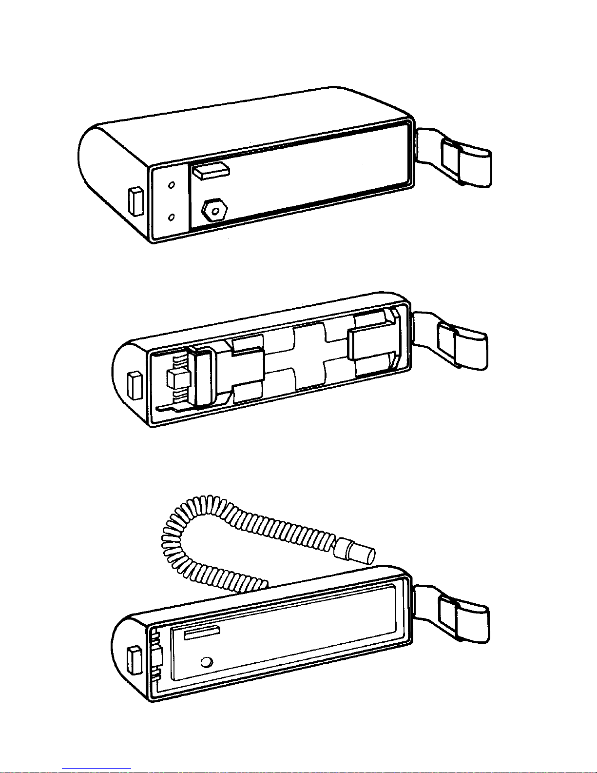
Rechargeable NiCad Battery Pack
Alkaline Battery Pack
(Holds 8 AA Batteries)
External DC Adaptor
MAINTENANCE
40
Page 49

41
MAINTENANCE
Operator-level maintenance of the
TRANSPAK
is limited to recharging the NiCad battery pack or replacing the AA batteries in
the non-rechargeable battery pack.
Recharging the NiCad Battery Pack
The NiCad battery pack provides more than five hours of
continuous operation when it is fully charged. The battery pack
charges to 85% of capacity in 16 hours and to full capacity in 24
hours. The battery pack slowly discharges when not in use and
should be recharged prior to use if it has been stored for two
weeks or more.
Removing and Replacing the Battery Pack
or DC Adaptor
To
remove
the battery pack or DC adaptor:
1.
Loosen latch at right-hand rear of
TRANSPAIC.
2.
Pull latch end of battery pack or adaptor away from back of
TRANSPAK,
and slide other end out of the retaining clip.
To reinstall the battery pack or DC adaptor:
1.
Make sure the edge of the battery pack or adaptor and the
mating O-ring in the unit are free of dirt.
2.
Slide the end of the battery pack or adaptor into the retaining
clip on the left-hand side of the
TRANSPAK
case.
3.
Carefully seat the pack onto the case and push it into place.
4.
Secure the latch on the right-hand side of the case.
Page 50
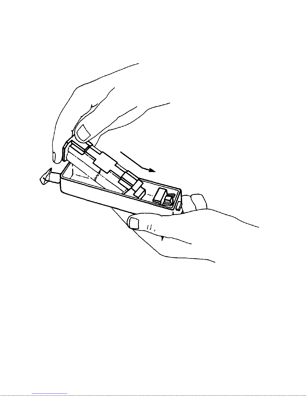
MAINTENANCE
Removing/Installing the Battery Pack Insert
4
2
Page 51

Replacing the AA Batteries
To remove old batteries:
1.
Remove the battery pack from the
TRANSPAK
unit.
2.
Remove the battery pack insert from the battery pack.
3.
Remove the batteries from the insert.
4.
Dispose of the old batteries.
43
MAINTENANCE
Be sure to follow the polarity labels on the battery
pack insert when installing new batteries. The
TRANS-
PAK
will not function properly and could be damaged
if batteries are improperly installed.
To install fresh batteries:
1.
Install the batteries in the battery pack insert.
2.
Reinstall the insert into the battery pack.
3.
Reinstall the battery pack onto the
TRANSPAK
unit.
Page 52

44
TROUBLESHOOTING THE TRANSPAK
IF:
1. The
TRANSPAK
fails to power on.
•
Batteries are not connected.
•
Batteries are dead.
•
AA batteries are inserted incorrectly; check polarity.
2. The
TRANSPAK
fails to perform a fix.
•
The antenna may be blocked.
•
Ensure that there are no obstructions between the an
-
tenna and the horizon.
•
If you are using an external antenna, ensure that it is
connected and that EXT is displayed on line 4 of the
STS screen.
•
There may be too few SVs visible to obtain a position fix.
•
Turn the rotary knob to the STS
position. If NEXT FIX
and a time are displayed, there will be enough SVs
visible at the displayed time. If NEXT FIX: NO
ALMANAC is displayed, the
TRANSPAK
must collect an
almanac from an SV, which takes 15 minutes.
•
The satellite almanac may be bad.
•
Turn the knob to the STS position. If NEXT FIX: NO
ALMANAC is displayed on line 3, the
TRANSPAK
must
collect an almanac from an SV.
3. A receiver fault number is displayed.
If the
TRANSPAK
detects internal errors, it displays them on line
3 of the STS screen. These are "never should happen" conditions. Some of these errors are mere nuisances; others
indicate
a serious problem which requires service — see
next page.
Page 53

45
essing error which may be transient. Turn the
TRANSPAK
off and then back on to clean the error. If
the error reoccurs, the
TRANSPAK
should be re-
turned for service.
16
Antenna feed line fault. This indicates an open or
a short on the external antenna input. Check the
external antenna cable for contamination (dirt,
salt spray) or for an open or a short.
A feed line fault should not occur when the internal antenna is in use. If it does, return the
TRANSPAK
for service.
32
Excessive bias dot. This indicates that the internal
oscillator has drifted. The
TRANSPAK
will continue
to operate, but should be returned for service if
acquisition times become excessive.
TROUBLESHOOTING THE TRANSPAK
3. Receiver faults (continued)
Fault
Number
Failure
01
The contents of the battery-backed memory have
been lost. The almanac and waypoints are cleared.
To recover, collect an almanac and re-enter your
waypoints. (The battery backup should not fail for
the life of the internal battery, which is approximately 7 years. If a failure does occur, the internal
battery must be replaced.
04, 06
07, 08
Channel alignment error. This is an internal proc-
Page 54

Liberia 1964
Local Astro
Luzon
Merchich
Montjong Lowe
Nigeria (Minna)
NAD-27, CONUS
NAD-83
Maui, Old HI (Hawaiian)
Oahu, Old HI (Hawaiian)
Kauai, Old HI (Hawaiian)
Oornoq
SierraLeon'60
S.America '56 (provisional)
CorregoAlegre (S.American)
Campolnchausp (S.American)
Chua Astro (S.American)
Yacare (S.American)
Tananarive'25++
Timbalai
Tokyo
Voirol
46
Kertau (Malayan Revised Triangulation)
+
North American 1927 (Alaska and Canada)
++ Tananarive Observatory 1925
*
Ordnance Survey of G. Britain 1936
* *
DATUM SELECTIONS
Maps are drawn based on a mathematical model of the earth's
shape. This is called a datum. For the displayed position to agree
with corresponding positions on a map, the datum must be
selected on the
TRANSPAK
Setup Screen (see page 38) to be the
same as the datum used to draw the map. The map's datum is
usually indicated in the map legend or title block.
The following datums are included in the
TRANSPAK.
Each name
is shown as displayed on the screen.
WGS-84
WGS-72
Adindan
Alaska/Canada+
ARC 1950
Australian '66
Bukit Rimpah
CampAreaAstro
Djakarta
European 1950
Geodetic 1949
Ghana
G.Britain '36*
Guam 1963
G. Segara
G. Serindung
Herat North
Hjorsey 1955
Hu-Tzu-Shan
Indian
Ireland 1965
Kertau Malay**
Page 55

TRANSPAK
WARRANTY RETURN PROCEDURES
1. Call Trimble Navigation
•
800-334-9595 from outside California, or
•
408-737-6940 from inside California
to request a Return Material Authorization (RMA) number.
Please have the TRANSPAK serial number ready to give to
the Customer Service representative.
2.
Write the RMA number here:
3.
Name/Organization/Address/Phone:
4.
Complete the Warranty Return Form on the reverse side of
this page.
5.
Package the equipment and ship prepaid with this page to:
Service Department
Trimble Navigation
617 North Mary Avenue
Sunnyvale, CA 94086
Page 56

TRANSPAK
WARRANTY RETURN FORM
RMA No.:
Serial No.:
Model/Part No.:
Physical Damage:
Software:
Screen in Use:
Operation Attempted:
Problem:
Operation/Electrical:
Turn-on/Power:
Improper Solution:
Specify Position:
Datum in Use:
Operating Conditions:
Other:
Full description of problem (please be as specific as possible):
Page 57

SAFETY
The case of the
TRANSPAK
conducts electricity, even
though it is made of plastic. When connecting the unit
to an external power source, be careful to avoid electrical shock just as if the case were metal.
The
TRANSPAK
is designed for rugged use in difficult
field environments. It will operate continuously in air
temperatures from 0° to 60°C (32° to 140°F) and in
environments with up to 100% humidity. However,
take reasonable care of the unit as with any other piece
of high-precision equipment.
Page 58

T
rimble Navigation
Trimble Navigation
(
Japan) Limited
(Europe) Limited
S
akurai Building 5F
12 Tonbridge Chambers
3
-15-15 Shiba, Minato-Ku
Pembury Road
T
okyo, Japan 105
Tonbridge, Kent TN9 2HZ
8
1-3-454-1321
United Kingdom
44-732-366201
Trimble
Navigation
TRIMBLE NAVIGATION LIMITED
645 North Mary Avenue
P.O. Box 3642
Sunnyvale, California 94086
(408) 730-2900
800-TRIMBLE
Telex: 671393 TRIMBLE UW
 Loading...