

Page 1
Trimble Construction Division
Trimble - Spectra Precision
5475 Kellenburger Road
Division
Dayton, Ohio 45424-1099
5475 Kellenburger Road
U.S.A.
Dayton, Ohio 45424 U.S.A.
+1-937-245-5600 Phone
+1-937-245-5600 Phone
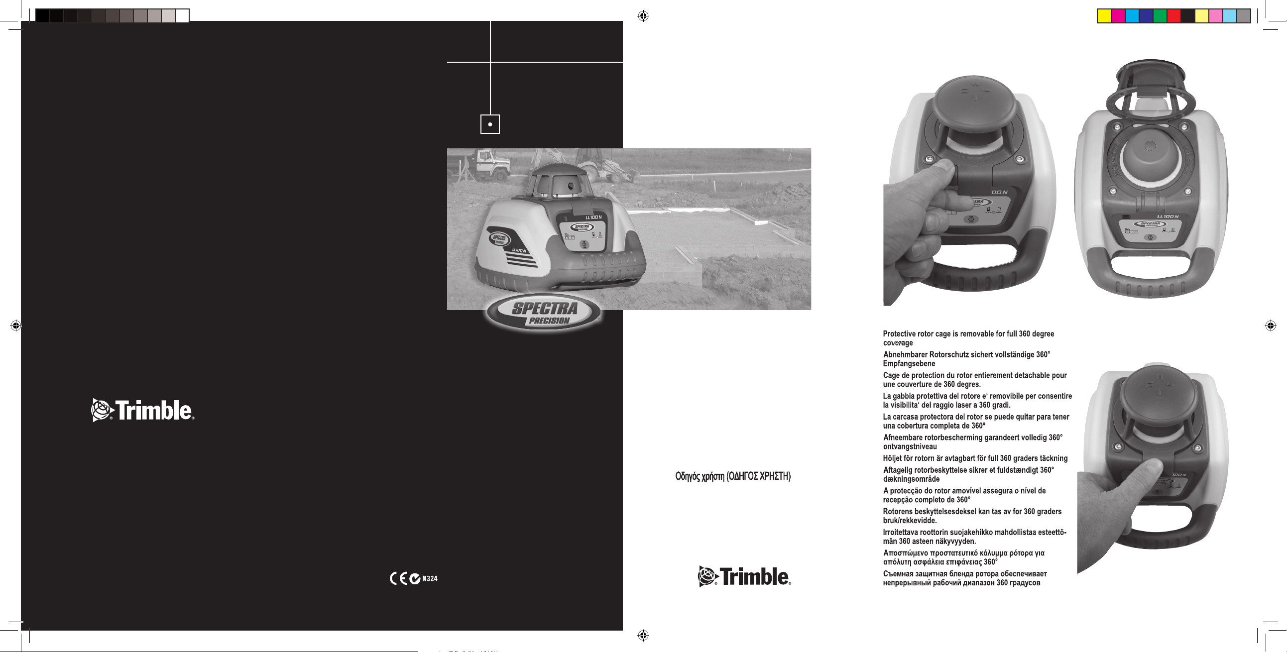
LL100N
User Guide
Bedienungsanleitung
Manuel de l´utilisateur
Guida per l´uso
Gúia del usuario
Gebruikershandleiding
Operatörshandbok
Betjeningsvejledning
Guia do Usuário
Bruksanvisning
Käyttäjän opas
Руководство пользователя
www.trimble.com www.trimble.com
© 2008, Trimble Navigation Limited. All rights reserved.
© 2017, Trimble Inc. All rights reserved
131131_00_LL100N_Cover_RevE.indd 1 28.09.2017 18:13:20
PN 94038 Rev. E (10/17)
PN Q103740 (01/08)
Page 2
6
7
9
8
10
3
11
15
14
15
12
15
14
5
1
4
2
131131_00_LL100N_Cover_RevE.indd 2 28.09.2017 18:13:20
13
94038 Rev. E (10/17)
Page 3
Thank you for choosing one of the Spectra Precision Lasers from the Trimble family of precision horizontal
lasers.
The LL100N is a simple-to-use laser that allows you to take accurate horizontal measurements, using a handheld or rod mounted receiver.
GB
TABLE OF CONTENTS
FOR YOUR SAFETY 5
COMPONENTS 6
How to Use the Laser System 6
Powering the Laser 6
Laser Setup 6
Turning On/Off the Laser 6
Activating/Deactivating Standby Mode 6
Using the Manual Mode 7
Using the Y- Single Slope Mode 7
APPLICATIONS 7
General Construction 7
Determining the Height of Instrument (HI) 7
Using the Y-Axis Single Slope Mode 7
CALIBRATION 8
Checking Calibration of the Y- and X-Axes 8
PROTECTING THE UNIT 8
CLEANING AND MAINTENANCE 8
PROTECTING THE ENVIRONMENT 8
WARRANTY 9
TECHNICAL DATA 9
FOR YOUR SAFETY
For hazardless and safe operation, read all the user guide instructions.
• Use of this product by people other than those trained on this product may result in exposure to hazardous
laser light.
• Do not remove warning labels from the unit.
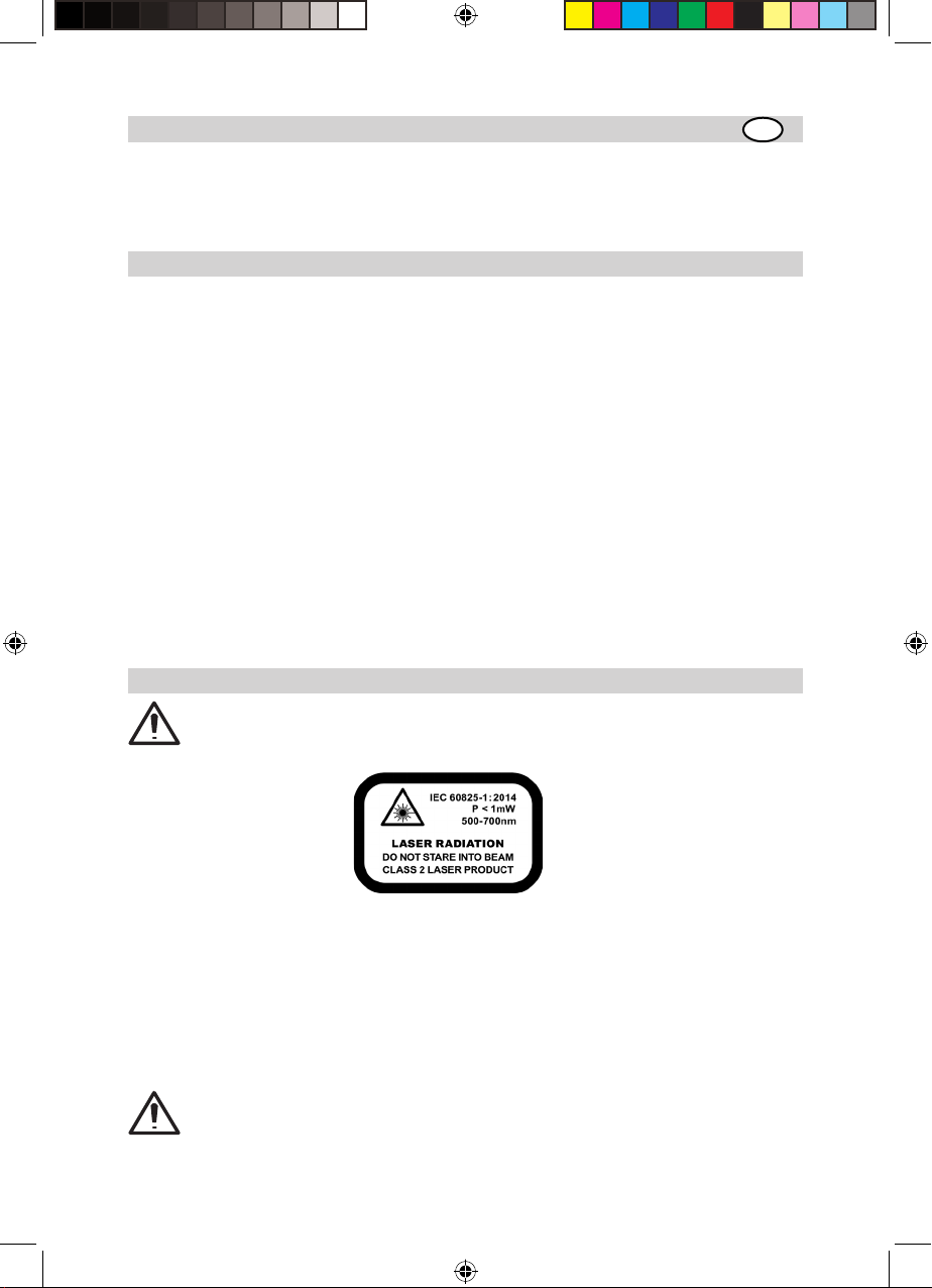
• The laser is subject to class 2.
• Never look into the laser beam or direct it to the eyes of other people.
• Always operate the unit in a way that prevents the beam from getting into people‘s eyes.
• If initial service is required, which results in the removal of the outer protective cover, removal must only be
performed by factory-trained personnel.
Caution: Use of other than the described user and calibration tools or other procedures may result
in exposure to hazardous laser light.
Caution: Using the unit different than described at the LL100N user guide, may result in unsafe
operation.
5
131131_01_LL100N_GB_RevE.indd 5 29.09.2017 10:21:35
Page 4

.COMPONENTS
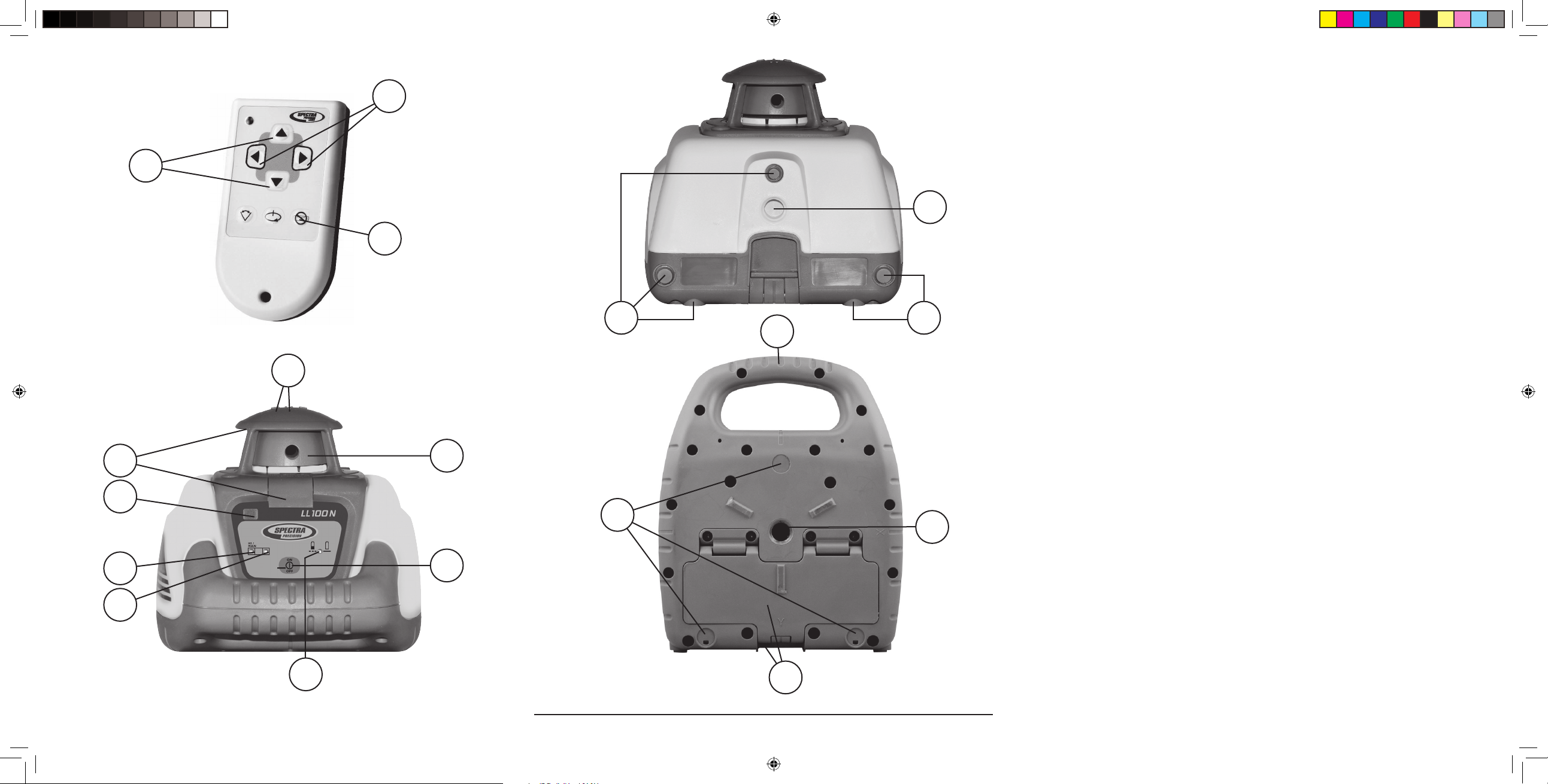
1 Power Button
2 Battery LED
3 Manual/Standby Button (remote control)
4 Leveling LED
5 Manual/HI-Warning LED
6 Up and Down Arrow Buttons (remote control)
7 Left and Right arrow Buttons (remote control)
8 Infrared-receiver for remote control
9 Removable Rotor Cage
10 Sighting Guides
11 Rotor/Beam Exit
12 Handle
13 Battery compartment/door
14 5/8x 11 Tripod Mounts
15 Rubber feet
How to Use the Laser System
Powering the Laser
Batteries
Installing Batteries
Open the battery door using your ngers, a coin or a screwdriver.
Insert batteries into the housing so that the negative poles are toward the bigger battery spiral spring.
Push down on the battery door until the latch “clicks” into position.
Laser Setup
Position the laser horizontally or vertically (tripod mount and rubber feet downward!) on a stable platform, wall
mount or tripod at the desired elevation. The laser recognizes automatically whether it is used horizontally or
vertically when switched on.
Note: The laser always operates in MANUAL mode in the Vertical position.
Turning On/Off the Laser
Press the power button 1 to turn on the laser.
Note: The laser always powers up in the automatic self-leveling mode. The LEDs (2, 4 and 5) are
turned on for 2 seconds.
The laser is level when the leveling indicator 4 is no longer ashing (once every second).
For the rst ve minutes after the laser self levels, the LED 4 lights solid. After ve minuts the LED 4 starts
ashing every four seconds to let you know the laser is still level while conserving battery life.
If the laser is positioned beyond it´s self-leveling range of ±8%, the laser beam, and manual and leveling
indicators ash simultaneously. Turn the unit off, reposition the laser within the self-leveling range and turn
it on again.
Note: If the laser is out of its self-leveling range and remains out of it for more than 10 minutes, the
unit shuts down completely.
Note: After the laser has been level for more than 5 minutes in horizontal mode,
the HI (height of instrument) alert activates. If the laser is disturbed (tripod bumped,
etc.) so that when it re-levels the laser beam elevation changes by more than 3 mm
(1/8 in.), the HI alert shuts down the laser and rotor, and the red LED ashes two times per second
(twice the manual-mode rate). To restore level, turn the laser off and on. After the laser has re-leveled,
check your initial reference elevation.
In order to switch the laser off, press the power button again.
Activating/Deactivating Standby Mode
Standby mode is a power-saving feature that conserves laser battery life.
Press and hold the remote control’s manual button for 3 seconds to activate standby mode.
Note: When standby mode is activated, the laser beam, rotor, self-leveling system, and LEDs shut
down, but the HI alert remains activated.
6
131131_01_LL100N_GB_RevE.indd 6 29.09.2017 10:21:35
Page 5
To let you know that the laser is in standby mode, the battery LED ashes every 4 seconds.
To deactivate standby mode and restore full operation of the laser, press and hold the remote control’s manual
button for 3 seconds.
The laser and all other functions turn on again.
Using the Manual Mode
In horizontal mode pressing the manual button on the remote control changes the laser from automatic selfleveling mode to Manual mode. Manual mode is indicated by the ashing (once every second) red LED 5.
In Manual mode (horizontal), the Y-axis can be sloped by pressing the Up- and Down-Arrow-buttons on the
remote control. Additionally, the X-axis can be sloped by pressing the Left- and Right-Arrow-buttons on the
remote control. To resume automatic self-leveling mode, press the manual button again.
In vertical mode, the laser is always in MANUAL mode. Pressing the up and down arrow buttons align the
laser beam to the right/left side, and the left and right arrow buttons at the remote control adjust the slope of
the laser beam.
To resume automatic self-leveling mode, press the manual button again.
Using the Y- Single Slope Mode
The Manual button on the remote control toggles the unit to Manual, the Y-axis Single Slope Mode, then
Automatic Mode. To activate the Y-axis single slope mode, press the manual button at the remote control twice.
This is indicated by the simultaneously ashing red 5 and green 4 LEDs (once every second).
In Y-axis single slope mode, the Y-axis can be sloped by pressing the Up- and Down-Arrow-buttons on the
remote control, while the X-axis remains in automatic self leveling mode (e.g. when setting up sloped ceilings
or drive ways).
To resume automatic self-leveling mode from Y-axis single slope mode, press the manual button again.
APPLICATIONS
General Construction
Determining the Height of Instrument (HI)
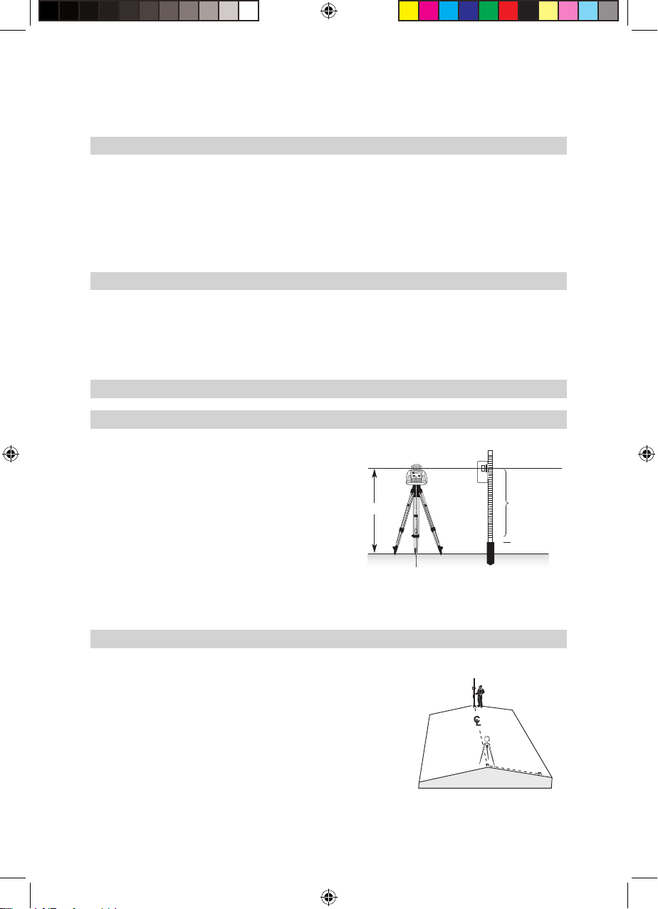
The height of instrument (HI) is the elevation of the laser’s
beam.
The HI is determined by adding the grade-rod reading to a
benchmark or known elevation.
1. Set up the laser and place the grade rod on a job-site
benchmark (BM) or known elevation.
HI
2. Slide the receiver up/down the grade rod until it shows an
on-grade reading.
3. Add the grade-rod reading to the benchmark to determine
the height of instrument.
Example:
Benchmark = 30.55 m (100.23 ft)
Rod reading = +1.32 m (+4.34 ft)
Height of instrument = 31.87 m (104.57 ft)
Use this HI as a reference for all other elevations.
Using the Y-Axis Single Slope Mode
1. Set up the laser over the reference point (A).
2. Look over the rotor to align the laser to the desired direction hub
in the axis that is supposed to be used in automatic self-leveling
mode. Turn the laser on the tripod until it is properly aligned.
3. Attach a receiver to a grade rod. Set the grade rod on the self-leveling
axis direction hub to check the laser’s elevation (B).
Note: Use this HI as a reference for checking the alignment
of the laser after setting the slope for the other axis.
4. Activate the Y-axis single slope mode by pressing the manual button
at the remote control twice.
5. Check the laser’s elevation on the slope axis directly in front of the
laser.
B
A
1.32 m (4.34 ft)
30.55 m (100.23 ft)
C
7
131131_01_LL100N_GB_RevE.indd 7 29.09.2017 10:21:35
Page 6
6. Set the grade rod on the slope axis direction hub to adjust the laser’s elevation without changing the height
of the receiver on the grade rod (C).
7. Press the up and down arrow buttons until you get an on-grade reading on the receiver.
8. Recheck the laser’s elevation in automatic self-leveling axis using the HI in step 3 (B).
If the HI has been changed, rotate the laser on the tripod until you get an on-grade reading again. Make sure,
you DON’T change the height of the receiver on the grade rod.
CALIBRATION
Checking Calibration of the Y- and X-Axes
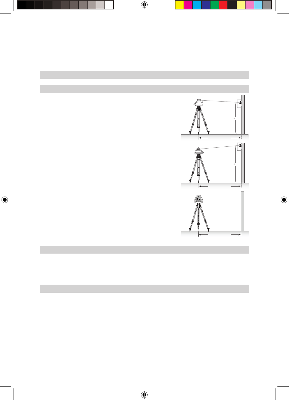
1. Set up the laser 30 m (100 ft) from a wall and allow it to level.
2. Raise/lower the receiver until you get an on-grade reading for the
+Y axis. Using the on-grade marking notch as a reference, make a
mark on the wall.
Note: For increased precision, use the ne-sensitivity setting
(1.5 mm/1/16 in.) on the receiver.
3. Rotate the laser 180° (-Y axis toward the wall) and allow the laser
to re-level.
4. Raise/lower the receiver until you get an on-grade reading for the
–Y axis. Using the on-grade marking notch as a reference, make a
mark on the wall.
5. Measure the difference between the two marks. If they differ more
than 6 mm at 30 m (1/4 inch at 100 feet), the laser needs calibrating.
6. After checking the Y-axis, rotate the laser 90°. Repeat the above
starting with the + X axis facing the wall.
Y+
30 m (100 ft)
-Y
30 m (100 ft)
x +
Y1
2
Y
Note: If calibration is required, please, refer to the
calibration instructions on our Trimble website
www.trimble.com/support.shtml
30 m (100 ft)
PROTECTING THE UNIT
Do not expose the unit to extreme temperatures or temperature changes (do not leave inside the car).
The unit is very robust and can resist damage if dropped even from tripod height. Before continuing your work,
always check the leveling accuracy. See Checking Calibration section.
The laser is water protected and can be used indoors and outdoors.
CLEANING AND MAINTENANCE
Dirt and water on the Rotor/Beam Exit (Component 11) will inuence beam quality and operating range
considerably.
Remove dirt on the housing with a lint-free, warm, wet and smooth cloth. Do not use harsh cleansers or
solvents.
Allow the unit to air dry after cleaning it.
8
131131_01_LL100N_GB_RevE.indd 8 29.09.2017 10:21:36
Page 7
PROTECTING THE ENVIRONMENT
The unit, accessories and packaging ought to be recycled. All plastic parts are marked for recycling according
to material type.
Do not throw used batteries into the garbage, water or re. Remove them in compliance with
environmental requirements.
Notice to Our European Union Customers
For product recycling instructions and more information, please go to:
http://www.trimble.com/Corporate/Environmental_Compliance.aspx
Instructions for Return to ERFC:
•WEEE is to be shipped to the ERFC, clearly stating WEEE on the delivery note and / or packaging
•Specic product number and serial number information is not required
•Additional return authorisation from Trimble Support is not required
•Delivery Address:
Trimble Europe B.V. WEEE Recycling
C/O Menlo logistics
Gate 19 to 26
Meerheide 43
5521 DZ
Eersel
The Netherlands
Conrmation of receipt of the returned WEEE will not be provided by the ERFC
Warranty
Trimble warrants the LL100N to be free of defects in material and workmanship for a period of 2 years. Trimble
or its authorized service center will repair or replace, at its option, any defective part, or the entire product, for
which notice has been given during the warranty period. If required, travel and per diem expenses to and from
the place where repairs are made will be charged to the customer at the prevailing rates. Customers should
send the product to Trimble Inc. or the nearest authorized service center for warranty repairs or exchange,
freight prepaid. Any evidence of negligent, abnormal use, accident, or any attempt to repair the product by
other than factory-authorized personnel using Trimble certied or recommended parts, automatically voids
the warranty. Special precautions have been taken to ensure the calibration of the laser; however, calibration
is not covered by this warranty. Maintenance of the calibration is the responsibility of the user. The foregoing
states the entire liability of Trimble regarding the purchase and use of its equipment. Trimble will not be held
responsible for any consequential loss or damage of any kind. This warranty is in lieu of all other warranties,
except as set forth above, including any implied warranty merchantability of tness for a particular purpose,
are hereby disclaimed. This warranty is in lieu of all other warranties, expressed or implied.
TECHNICAL DATA
Leveling accuracy
Rotation: appr. 600 rpm
Operational area
Laser type: red diode laser 650 nm
Laser class: Class 2
Self-leveling range: appr. ± 5°
Leveling time: appr. 30 sec
Leveling indicators: LED ashes
Laser beam diameter1: appr. 5 mm
Operating range using remote control: up to 30m (100 ft)
Power supply: 2 x 1.5V Mono cells type D (LR20)
Battery life1: alkaline: 80 hours; NiMH: 35 hours
Dust- and waterproof: IP54
Operating temp.: 23°F...113°F (-5°C ... 45°C)
Storage temp.: -4°F...158°F (-20°C ... 70°C)
Tripod attachments: 5/8 x 11 horizontally and vertically
Weight: 1.5 kg (3.3 lbs)
Low voltage indication: ashing/shining of the battery indicator
Low voltage disconnection: unit shuts off
1,3
: ± 3 mm/30 m, 1/8“ @ 100 ft, 20 arc seconds
1,2
: appr. 350 m (1150 feet) diameter with detector
1) at 21° Celsius
2) under optimal atmospheric circumstances
3) along the axis
9
131131_01_LL100N_GB_RevE.indd 9 29.09.2017 10:21:36
Page 8

DECLARATION OF CONFORMITY
We
The managing director
Electro-Magnetic Compatibility
Declaration of Conformity
This digital apparatus does not exceed the Class B Limits for radio noise for digital apparatus set out in the
Radio Interference Regulations of the Canadian Department of Communications.
This device complies with part 15 off the FCC rules. Operation is subject to the condition that this device does
not cause harmful interference.
• Reorient or relocate the receiving antenna.
• Increase the separation between the product and the receiver.
• For more information, consult your dealer or an experienced radio/television technician.
Trimble Kaiserslautern GmbH declare under our sole responsibility that the product LL100N to
which this declaration relates is in conformity with the following standards EN 61000-6-3:2007 +
A1:2010, EN 61000-6-2:2005 and EN 60825-1:2014
following the provisions of directive Electromagnetic compatibility 2004/108/EC.
Note: The product been tested and found to comply with the limits for a Class B digital device,
pursuant to part 15 of the FCC rules. These limits are designed to provide reasonable protection
against harmful interference in a residential installation. The product generates, uses and can
radiate radio frequency energy and, if not installed and used in accordance with the instructions,
may cause harmful interference to radio or television reception, which can be determined by turning
the product off and on. The user is encouraged to try to eliminate the interference by one or more
of the following measures:
Caution: Changes or modications to the product that are not expressly approved by Trimble could
void authority to use the equipment.
10
131131_01_LL100N_GB_RevE.indd 10 29.09.2017 10:21:36
Page 9

Service and Customer Advice
North America
Trimble Spectra Precision Division
5475 Kellenburger Road
Dayton, Ohio 45424-1099, USA
+1-937-245-5600 Phone
www.trimble.com
www.spectraprecision.com
www.spectralasers.com
Europe
Trimble Kaiserslautern GmbH
Am Sportplatz 5
67661 Kaiserslautern
GERMANY
+49-6301-711414 Phone
+49-6301-32213 Fax
Latin America
Trimble Navigation Limited
6505 Blue Lagoon Drive
Suite 120
Miami, FL 33126
U.S.A.
+1-305-263-9033 Phone
+1-305-263-8975 Fax
Africa & Middle East
Trimble Export Middle-East
P.O. Box 17760
Jebel Ali Free Zone, Dubai
UAE
+971-4-881-3005 Phone
+971-4-881-3007 Fax
Asia-Pacic
Trimble Navigation
Australia PTY Limited
Level 1/120 Wickham Street
Fortitude Valley, QLD 4006
AUSTRALIA
+61-7-3216-0044 Phone
+61-7-3216-0088 Fax
China
Trimble Beijing
Room 2805-07, Tengda Plaza,
No. 168 Xiwai Street
Haidian District
Beijing, China 100044
+86 10 8857 7575 Phone
+86 10 8857 7161 Fax
www.trimble.com.cn
83
131131_14_LL100N_Service_RevE.indd 83 10.10.2017 15:54:20
Page 10

84
131131_14_LL100N_Service_RevE.indd 84 10.10.2017 15:54:20
 Loading...