

Page 1

User Guide
Trimble
®
SNB900
Radio-Modem
Version 1.0
Revision B
May 2005
Page 2

Contact Information
Trimble Navigation Limited
Geomatics and Engineering Division
5475 Kellenburger Road
Dayton, Ohio 45424-1099
USA
+1-937-245-5600 Phone
+1-937-233-9004 Fax
www.trimble.com
Copyright and Trademarks
© 2005, Trimble Navigation Limited. All rights reserved.
Trimble and the Globe & Triangle logo are trademarks of
Trimble Navigation Limited, registered in the United States
Patent and Trademark Office and in other countries. CMR,
CMR+, MS750, SiteNet, TRIMCOMM, and TRIMMARK are
trademarks of Trimble Navigation Limited.
Microsoft, Windows, and Windows NT are either registered
trademarks or trademarks of Microsoft Corporation in the
United States and/or other countries.
All other trademarks are the property of their respective
owners.
Release Notice
This is the May 2005 release (Revision B) of the Trim ble
SNB900 Radio-Modem User Guide. It applies to version 1.0 of
the Trimble SNB900 radio-modem.
The following limited warranties give you specific legal
rights. You may have others, which vary from
state/jurisdiction to state/jurisdiction.
Hardware Limited Warranty
Trimble Navigation Limited warrants that this hardware
product (the “Product”) will perform substantially in
accordance with published specifications and be
substantially free of defects in material and workmanship for
a period of one (1) year starting from the date of delivery. The
warranty set forth in this paragraph shall not apply to
software products.
Software License, Limited Warranty
This Trimble software product, whether provided as a standalone computer software product, built into hardware
circuitry as firmware, embedded in flash memory, or stored
on magnetic or other media, (the “Software”) is licensed and
not sold, and its use is governed by the terms of the relevant
End User License Agreement (“EULA”) included with the
Software. In the absence of a separate EULA included with
the Software providing different limited warranty terms,
exclusions and limitations, the following terms and
conditions shall apply. Trimble warrants that this Trimble
Software product will substantially conform to Trimble’s
applicable published specifications for the Software for a
period of one (1) year, starting from the date of delivery.
Warranty Remedies
Trimble's sole liability and your exclusive remedy under the
warranties set forth above shall be, at Trimble’s option, to
repair or replace any Product or Software that fails to
conform to such warranty ("Nonconforming Product") or
refund the purchase price paid by you for any such
Nonconforming Product, upon your return of any
Nonconforming Product to Trimble in accordance with
Trimble’s standard return material authorization procedures.
Warranty Exclusions and Disclaimer
These warranties shall be applied only in the event and to the
extent that (i) the Products and Software are properly and
correctly installed, configured, interfaced, maintained,
stored, and operated in accordance with Trimble's relevant
operator's manual and specifications, and; (ii) the Products
and Software are not modified or misused. The preceding
warranties shall not apply to, and Trimble shall not be
responsible for defects or performance problems resulting
from (i) the combination or utilization of the Product or
Software with hardware or software products, information,
data, systems, interfaces or devices not made, supplied or
specified by Trimble; (ii) the operation of the Product or
Software under any specification other than, or in addition
to, Trimble's standard specifications for its products; (iii) the
unauthorized, installation, modification, or use of the
Product or Software; (iv) damage caused by accident,
lightning or other electrical discharge, fresh or salt water
immersion or spray; or (v) normal wear and tear on
consumable parts (e.g., batteries). Trimble does not warrant
or guarantee the results obtained through the use of the
Product.
THE WARRANTIES ABOVE STATE TRIMBLE'S ENTIRE
LIABILITY, AND YOUR EXCLUSIVE REMEDIES, RELATING TO
PERFORMANCE OF THE PRODUCTS AND SOFTWARE.
EXCEPT AS OTHERWISE EXPRESSLY PROVIDED HEREIN, THE
PRODUCTS, SOFTWARE, AND ACCOMPANYING
DOCUMENTATION AND MATERIALS ARE PROVIDED “AS-IS”
AND WITHOUT EXPRESS OR IMPLIED WARRANTY OF ANY
KIND BY EITHER TRIMBLE NAVIGATION LIMITED OR
ANYONE WHO HAS BEEN INVOLVED IN ITS CREATION,
PRODUCTION, INSTALLATION , OR DISTRIBUTION
INCLUDING, BUT NOT LIMITED TO, THE IMPLIED
WARRANTIES OF MERCHANTABILITY AND FITNESS FOR A
PARTICULAR PURPOSE, TITLE, AND NONINFRINGEMENT.
THE STATED EXPRESS
OBLIGATIONS OR LIABILITIES ON THE PART OF TRIMBLE
ARISING OUT OF, OR IN CONNECTION WITH, ANY PRODUCTS
OR SOFTWARE. SOME STATES AND JURISDICTIONS DO NOT
ALLOW LIMITATIONS ON DURATION OR THE EXCLUSION OF
AN IMPLIED WARRANTY, SO THE ABOVE LIMITATION MAY
NOT APPLY TO YOU.
TRIMBLE NAVIGATION LIMITED IS NOT RESPONSIBLE FOR
THE OPERATION OR FAILURE OF OPERATION OF GPS
SATELLITES OR THE AVAILABILITY OF GPS SATELLITE
SIGNALS.
WARRANTIES ARE IN LIEU OF ALL
Limitation of Liability
TRIMBLE’S ENTIRE LIABILITY UNDER ANY PROVISION
HEREIN SHALL BE LIMITED TO THE AMOUNT PAID BY YOU
FOR THE PRODUCT OR SOFTWARE LICENSE. TO THE
MAXIM UM EXTENT PERMITTED B Y APPLICABL E LAW, IN NO
EVENT SHALL TRIMBLE OR ITS SUPPLIERS BE LIABLE FOR
ANY INDIRECT, SPECIAL, INCIDENTAL OR CONSEQUENTIAL
DAMAGES WHATSOEVER UNDER ANY CIRCUMSTANCE OR
LEGAL THEORY RELATING IN ANY WAY TO THE PRODUCTS,
SOFTWARE AND ACCOMPANYING DOCUMENTATION AND
MATERIALS, (INCLUDING, WITHOUT LIMITATION,
DAMAGES FOR LOSS OF BUSINESS PROFITS, BUSINESS
INTERRUPTION , LOSS OF BUSINESS INFORMATION , OR ANY
OTHER PECUNI ARY LOSS), REGARDLESS WHETHE R TRIMBLE
HAS BEEN ADVISED OF THE POSSIBILITY OF ANY SUCH LOSS
Page 3
AND REGARDLESS OF THE COURSE OF DEALING WHICH
DEVELOPS OR HAS DEVELOPED BETWEEN YOU AND
TRIMBLE. BECAUSE SOME STATES AND JURISDICTIONS DO
NOT ALLOW THE EXCLUSION OR LIMITATION OF LIABILITY
FOR CONSEQUENTIAL OR INCIDENTAL DAMAGES, THE
ABOVE LIMITATION MAY NOT APPLY TO YOU.
NOTE: THE ABOVE LIMITED WARRANTY PROVISIONS MAY
NOT APPLY TO PRODUCTS OR SOFTWARE PURCHASED IN
THE EUROPEAN UNION.
TRIMBLE DEALER FOR APPLICABLE WARRANTY
INFORMATION.
Notices
Class B Statement – Notice to Users. This
equipment has been tested and found to comply
with the limits for a Class B digital device,
pursuant to Part 15 of the FCC rules, and Part 90
of the FCC rules. These limits are designed to
provide reasonable protection against harmful interference
in a residential installation. This equipment generates, uses,
and can radiate radio frequency energy and, if not installed
and used in accordance with the instructions, may cause
harmful interference to radio communication. However,
there is no guarantee that interference will not occur in a
particular installation. If this equipment does cause harmful
interference to radio or television reception, which can be
determined by turning the equipment off and on, the user is
encouraged to try to correct the interference by one or more
of the following measures:
– Reorient or relocate the receiving antenna.
– Increase the separation between the equipment and the
receiver.
– Connect the equipment into an outlet on a circuit
different from that to which the receiver is connected.
– Consult the dealer or an experienced radio/TV technician
for help.
Changes and modifications not expressly approved by the
manufacturer or registrant of this equipment can void your
authority to operate this equipment under Federal
Communications
PLEASE CONTACT YOUR
Before operating these radio-modems, users are
legally required to obtain frequency licenses, as
required by the country-of-use. Please contact your
local communications governing agency for the
licensing requirements for each of these radiomodems.
Safety
You must maintain a minimum separation distance of 21 cm
(approximately 8in) between yourself and the radiating
antenna for this device to satisfy the RF Exposure
requirements of the FCC and Industry Canada. The antenna
may not be co-located with any other transmitting device.
For mobile operation, the maximum gain of the antenna
must not exceed 5 dBi.
Trimble and the Environment
For product recycling instructions and more information,
please go to www.trimble.com/environment/summary.html.
Europe
To recycle Trimble WEEE (Waste from
Electrical and Electronic Equipment), do one of
the following:
– call +31 497 53 2436, and ask for the WEEE
Associate
– mail a request to:
Trimble Europe BV
c/o Menlo Worldwide Logistics
Meerheide 455521 DZ Eersel, NL
Taiwan - Battery Recycling Requirements
The product contains a removable Lithium-Ion
battery. Taiwanese regulations require that
waste batteries are recycled.
Page 4

Declaration of Conformity (Canada)
Company name Trimble Navigation Limited
Company number 1756
Company address Trimble Geomatics and Engineering Division
Model number SNB900
Specification code 1756A-48480
Specification RSS210
Issue 3
Band 650KG1D
Power 0.832 watt
From frequency 902.6 MHz
To fr eq u en c y 927.6 MHz
5475 Kellenburger Road
Dayton, Ohio 45424-1099
USA
800-538-7800 (toll free in USA)
+1-937-233-8921 Phone
+1-937-233-9004 Fax
Page 5

Safety
Safety 1
1.1
Warnings and Cautions
Always observe safety instructions that are presented in the following
format:
C
C
1.2 Battery Safety
C
WARNING – A Warning alerts you to a possible hazard or unsafe practice
that could result in serious injury or property damage. A Warning
describes how to protect people and/or equipment from this risk.
CAUTION – A Caution alerts you to a possible risk of damage to the
equipment and/or loss of data. A Caution describes how to protect the
equipment and/or data from this risk.
WARNING – Do not damage the rechargeable Lithium-ion battery. A
damaged battery can cause an explosion or fire, and can result in personal
injury and/or property damage.
To prevent injury or damage:
- Do not use or charge the battery if it appears to be damaged. Signs of
damage include, but are not limited to, discoloration, warping, and
leaking battery fluid.
- Do not expose the battery to fire, high temperature, or direct sunlight.
- Do not immerse the battery in water. /
- Do not use or store the battery inside a vehicle during hot weather.
- Do not drop or puncture the battery.
- Do not open the battery or short-circuit its contacts.
SNB900 Radio-Modem User Guide v
Page 6

Safety
C
C
WARNING – Avoid contact with the rechargeable Lithium-ion battery if it
appears to be leaking. Battery fluid is corrosive, and contact with it can
result in personal injury and/or property damage.
To prevent injury or damage:
- If the battery leaks, avoid contact with the battery fluid.
- If battery fluid gets into your eyes, immediately rinse your eyes with
clean water and seek medical attention. Do not rub your eyes!
- If battery fluid gets onto your skin or clothing, immediately use clean
water to wash off the battery fluid.
WARNING – Charge and use the rechargeable Lithium-ion battery only in
strict accordance with the instructions. Charging or using the battery in
unauthorized equipment can cause an explosion or fire, and can result in
personal injury and/or equipment damage.
To prevent injury or damage:
- Do not charge or use the battery if it appears to be damaged or leaking.
- Charge the Lithium-ion battery only in a Trimble product that is specified
to charge it. Be sure to follow all instructions that are provided with the
battery charger.
- Discontinue charging a battery that gives off extreme heat or a burning
odor.
- Use the battery only in Trimble equipment that is specified to use it.
- Use the battery only for its intended use and according to the
instructions in the product documentation.
1.3 Disposing of the Battery
C
vi SNB900 Radio-Modem User Guide
WARNING – The SNB900 radio-modem contains a Lithium-ion battery
and should not be disposed of with general refuse. Dispose of the SNB900
radio-modem in accordance with all local codes and regulations for
products containing lithium ion batteries. Contact your local
environmental control or disposal agency for further details.
Page 7

1.4 Battery Consumption
Safety
C
1.5 Installing Antennas
C
1.6 Operation and Storage
C
CAUTION – Turbo mode increases power consumption by approximately
20%. If you work in Turbo mode, the battery will run down faster.
CAUTION – For your own safety, and in terms of the RF Exposure
requirements of the FCC, always observe the precautions listed here.
-Always maintain a minimum separation distance of 21 cm (approximately
8 inches) between yourself and the radiating antenna on the SNB900
radio-modem.
- Do not co-locate the antenna with any other transmitting device.
- For mobile operation, do not allow the maximum gain of the antenna to
exceed 5 dBi.
CAUTION – Do not operate or store the SNB900 radio-modem outside the
temperature range specified. Doing so can damage the instrument.
SNB900 Radio-Modem User Guide vii
Page 8

Safety
viii SNB900 Radio-Modem User Guide
Page 9

Contents
1 Safety. . . . . . . . . . . . . . . . . . . . . . . . . . . v
Warnings and Cautions . . . . . . . . . . . . . . . . . . . . . . . . . . . . . . . . . . . v
Battery Safety . . . . . . . . . . . . . . . . . . . . . . . . . . . . . . . . . . . . . . . . . v
Disposing of the Battery . . . . . . . . . . . . . . . . . . . . . . . . . . . . . . . . . . vi
Battery Consumption . . . . . . . . . . . . . . . . . . . . . . . . . . . . . . . . . . . vii
Installing Antennas. . . . . . . . . . . . . . . . . . . . . . . . . . . . . . . . . . . . . vii
Operation and Storage . . . . . . . . . . . . . . . . . . . . . . . . . . . . . . . . . . . vii
1 Introduction . . . . . . . . . . . . . . . . . . . . . . . 1
Welcome . . . . . . . . . . . . . . . . . . . . . . . . . . . . . . . . . . . . . . . . . . . . 1
Related Information . . . . . . . . . . . . . . . . . . . . . . . . . . . . . . . . . . . . .2
Technical Assistance . . . . . . . . . . . . . . . . . . . . . . . . . . . . . . . . . . . . .2
Your Comments . . . . . . . . . . . . . . . . . . . . . . . . . . . . . . . . . . . . . . . .3
2 Getting Started . . . . . . . . . . . . . . . . . . . . . 5
Frequency Band . . . . . . . . . . . . . . . . . . . . . . . . . . . . . . . . . . . . . . . .6
Features . . . . . . . . . . . . . . . . . . . . . . . . . . . . . . . . . . . . . . . . . . . . .6
Front Panel Display. . . . . . . . . . . . . . . . . . . . . . . . . . . . . . . . . . . . . .8
Menus . . . . . . . . . . . . . . . . . . . . . . . . . . . . . . . . . . . . . . . . . . . . . .9
Selecting a menu . . . . . . . . . . . . . . . . . . . . . . . . . . . . . . . . . . . 9
Main menus . . . . . . . . . . . . . . . . . . . . . . . . . . . . . . . . . . . . . .9
Ports . . . . . . . . . . . . . . . . . . . . . . . . . . . . . . . . . . . . . . . . . . . . . . 12
Cables and Accessories . . . . . . . . . . . . . . . . . . . . . . . . . . . . . . . . . . 13
Additional parts. . . . . . . . . . . . . . . . . . . . . . . . . . . . . . . . . . . 13
Optional accessories . . . . . . . . . . . . . . . . . . . . . . . . . . . . . . . . 13
SNB900 Radio-Modem User Guide ix
Page 10

Contents
Use and Care . . . . . . . . . . . . . . . . . . . . . . . . . . . . . . . . . . . . . . . . . 14
Use and care of the internal battery . . . . . . . . . . . . . . . . . . . . . . 14
3 Configuration and Installation . . . . . . . . . . . . 17
Configuring the SNB900 Radio-Modem Using the Front Panel Display . . . . 18
Status menu . . . . . . . . . . . . . . . . . . . . . . . . . . . . . . . . . . . . . 18
Network menu . . . . . . . . . . . . . . . . . . . . . . . . . . . . . . . . . . . 22
Mode menu . . . . . . . . . . . . . . . . . . . . . . . . . . . . . . . . . . . . . 22
Turbo Mode menu . . . . . . . . . . . . . . . . . . . . . . . . . . . . . . . . . 23
Port Configuration menu: LEMO Port Configuration and Modem Port
Configuration . . . . . . . . . . . . . . . . . . . . . . . . . . . . . . . . . . 24
Display Configuration menu . . . . . . . . . . . . . . . . . . . . . . . . . . . 25
Configuring the SNB900 Radio-Modem Using the WinFlash Utility . . . . . . 26
Procedure. . . . . . . . . . . . . . . . . . . . . . . . . . . . . . . . . . . . . . . 26
Upgrading the SNB900 Radio-Modem Firmware . . . . . . . . . . . . . . . . . . 32
Installing the SNB900 Radio-Modem in the Field . . . . . . . . . . . . . . . . . . 32
Important notes . . . . . . . . . . . . . . . . . . . . . . . . . . . . . . . . . . 32
Installing the SNB900 radio-modem as a base. . . . . . . . . . . . . . . . 33
Installing the SNB900 radio-modem as a repeater . . . . . . . . . . . . . 34
Installing the SNB900 radio-modem as a rover . . . . . . . . . . . . . . . 35
Installing antennas. . . . . . . . . . . . . . . . . . . . . . . . . . . . . . . . . 35
4 Antenna Details . . . . . . . . . . . . . . . . . . . . 37
Omni-Directional Antennas . . . . . . . . . . . . . . . . . . . . . . . . . . . . . . . 38
SNB900 Radio-Modem Antenna Range . . . . . . . . . . . . . . . . . . . . . . . . 38
Energy Patterns . . . . . . . . . . . . . . . . . . . . . . . . . . . . . . . . . . . . . . . 39
5 Troubleshooting . . . . . . . . . . . . . . . . . . . . 41
Servicing . . . . . . . . . . . . . . . . . . . . . . . . . . . . . . . . . . . . . . . . . . . 41
Status Messages . . . . . . . . . . . . . . . . . . . . . . . . . . . . . . . . . . . . . . . 42
Index . . . . . . . . . . . . . . . . . . . . . . . . . . 47
x SNB900 Radio-Modem User Guide
Page 11

CHAPTER
1
Introduction 1
In this chapter:
Q Welcome
Q Related Information
Q Technical Assistance
Q Your Comments
1.1 Welcome
This manual describes how to set up, install, and use a Trimble®
SNB900 radio-modem.
Even if you have used other radio-modems, Trimble recommends that
you read this manual to learn about the special features of the product.
B
Tip – For an interactive look at GPS, go to the Trimble website at
www.trimble.com.
SNB900 Radio-Modem User Guide 1
Page 12

1 Introduction
1.2 Related Information
Sources of related information include the following:
• Release notes
To read a summary of new and enhanced software features, read
about small changes to the documentation, and receive step-bystep instructions for installing the software, open the release
notes.
• Support page on the Trimble website
For additional information such as service bulletins and FAQs,
go to www.trimble.com/support.shtml. The website also has
related utility programs, firmware, and software patches that you
can download.
• Trimble training courses
Consider a training course to help you use this GPS system to its
fullest potential. For more information, go to the Trimble
website at www.trimble.com/training.shtml.
• Extended warranty
For information about extended warranty programs for
hardware and firmware, contact your local Trimble dealer.
1.3 Technical Assistance
If you cannot find the information you need, contact your local dealer.
Alternatively, do one of the following:
• Request technical support:
a. Go to www.trimble.com.
b. Click the
Support button at the top of the screen. The
Support A–Z list of products appears.
c. Scroll to the bottom of the list.
d. Click the
submit an inquiry link. A form appears.
e. Complete the form and then click
• Send an e-mail to trimble_support@trimble.com.
2 SNB900 Radio-Modem User Guide
Send.
Page 13

1.4 Your Comments
Your feedback about the supporting documentation helps us to
improve it with each revision. Send an e-mail with your comments to
ReaderFeedback@trimble.com.
Introduction 1
SNB900 Radio-Modem User Guide 3
Page 14

1 Introduction
4 SNB900 Radio-Modem User Guide
Page 15

CHAPTER
2
Getting Started 2
In this chapter:
Q Frequency Band
Q Features
Q Front Panel Display
Q Menus
Q Ports
Q Cables and Accessories
Q Use and Care
The rugged Trimble SNB900 radio-modem is packaged in a
weatherproof housing, making it ideal for harsh environments, such as
those associated with construction, seismic, and mining surveys. To
establish a robust wireless data broadcast network for real-time
differential and real-time kinematic GPS applications, use the versatile
SNB900 radio-modem with a Trimble GPS rover.
SNB900 Radio-Modem User Guide 5
Page 16

2 Getting Started
2.1 Frequency Band
The SNB900 radio-modem operates in the 902–928 MHz frequency
band. It is certified for unlicensed use in this band as a transmitter,
pursuant to 47 C.F.R. §§ 15.247, 15.249 (1993) (unlicensed, low-power
devices) Subpart C of Part 15 of FCC Rules regarding Spread Spectrum
Systems for the United States. License-free operation in Canada is
covered by RSS-210 of Industrie Canada.
The SNB900 radio-modem is available with a reduced frequency range
for use in Australia and New Zealand. It is available in single-frequency
mode for use in other countries.
Note – The 902–928 MHz band is a shared-use band and as such is
subject to interfering signals.
This frequency band is allocated to other uses, including cellular
telephony, in other parts of the world. Regulations regarding its use
vary greatly from country to country. Use of the radio-modem outside
the United States, Canada, Australia, and New Zealand must be
approved by the local radio authority. Contact your local radio
communications governing authority for regulations and restrictions
on operation in the country or area where you want to use the SNB900.
2.2 Features
The SNB900 radio-modem has the following standard features:
• Frequency :
– 902–928 MHz in USA/Canada
– 921–928 MHz in New Zealand
– 916–928 MHz in Australia
– Single-frequency configuration for specific countries
• +30 dBm (1 Watt)
• Frequency hopping on 50 channels
6 SNB900 Radio-Modem User Guide
Page 17

Getting Started 2
• High-speed wireless data rate
• Interfaces with Trimble survey-grade and construction-grade
GPS receivers
• Rugged, weatherproof construction
• Internal battery
• Two-line, 16-character VFD display
• Compatible with Trimble CMR+
• Operational parameters configured using the WinFlash utility, a
™
and RTCM SC-104
handheld controller, or the front panel
• Can be configured as a base, repeater, or rover
• Compatible with TRIMCOMM
™
900, SiteNet™ 900 and SNR900
external radios, and Trimble 5700 and 5800 internal 900 MHz
radios
Note – In this manual, CMR
™
and CMR+ formats are both represented by
CMR+.
SNB900 Radio-Modem User Guide 7
Page 18
2 Getting Started
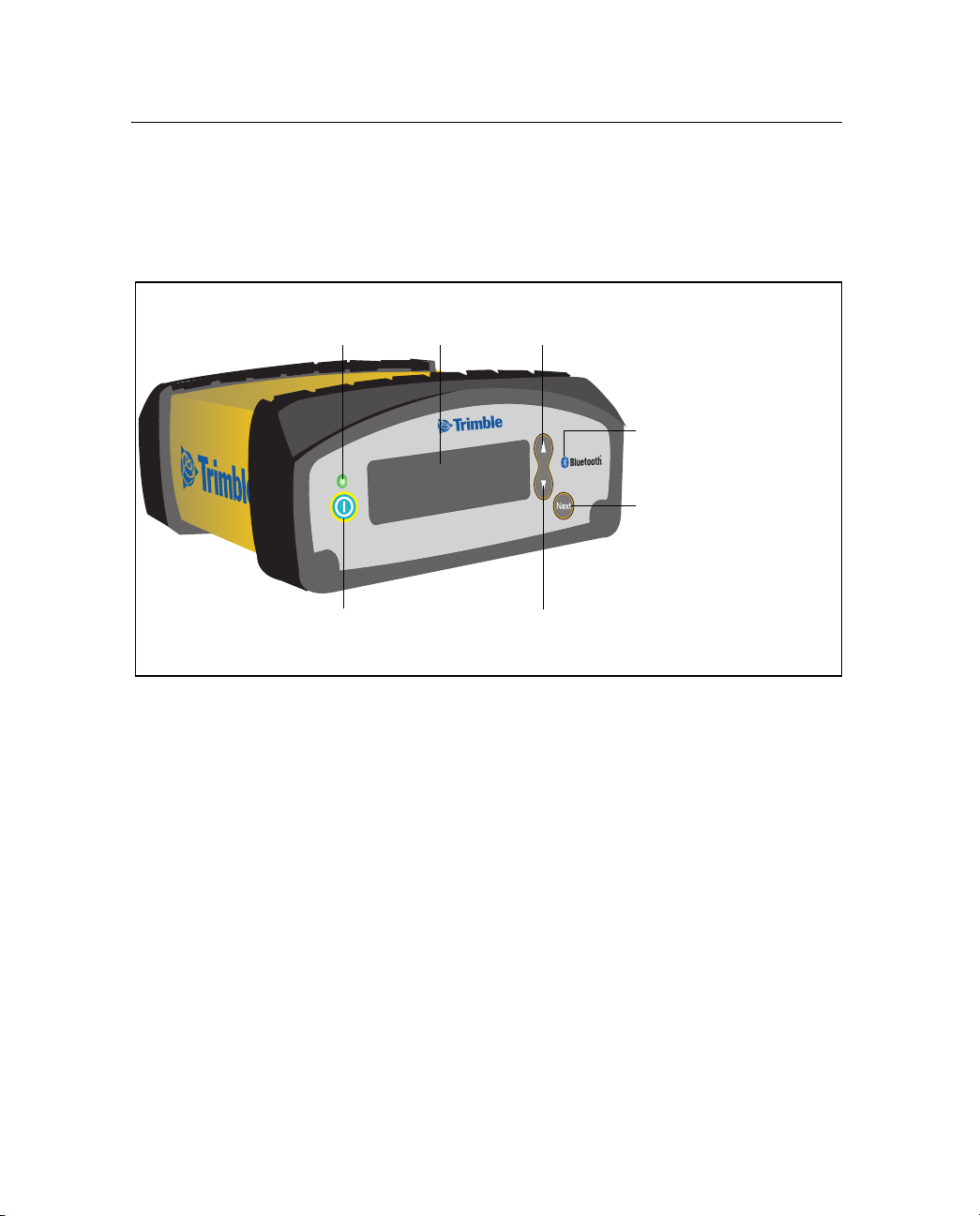
2.3 Front Panel Display
The front panel of the SNB900 radio-modem (see Figure 2.1) has a
Vacuum Fluorescent Display (VFD) that shows the network frequency
and radio status, as well as error messages.
Power LED
Power button
Figure 2.1 Front view of the SNB900 radio-modem
Front panel (display)
Down button
Up button
Logo showing location
of Bluetooth antenna
Next button
8 SNB900 Radio-Modem User Guide
Page 19

Getting Started 2
2.4 Menus
When you start the SNB900 radio-modem, the default Status menu
screen is displayed on the front panel. This screen shows a summary of
the radio-modem’s configuration settings.
24.1 Selecting a menu
To move to a different menu, press the button on the front panel
display. To scroll through the available settings in a menu, press the Up
button
24.2 Main menus
or the Down button .
Ta bl e 2 .1 lists each main menu and describes its use.
Table 2.1 Main menus
Use this menu ... To ... For details, see ...
Status View information about the operation of the
radio.
Network Select an operating network for the radio-
modem. Each network has a unique hopping
pattern to help reduce interference from nearby
radio transmitters.
Mode Specify whether the radio-modem is to operate
as a base, a rover, or as one of up to four
repeaters.
Turbo Mode Enable or disable Turbo mode. Use Turbo mode
in areas of high RF interference to improve
performance.
Port Config
LEMO Port Config
Modem Port Config
Display Config Configure when the display will power down. page 25
Configure the settings for two of the ports that
are on the back of the radio-modem (the sevenpin LEMO port and the 26-pin Modem port).
page 18
page 22
page 22
page 23
page 24
Note – The radio-modem unit settings determine which menus are
available.
SNB900 Radio-Modem User Guide 9
Page 20

2 Getting Started
Ta bl e 2 .2 lists the possible settings and the default setting for each main
menu.
Table 2.2 Settings
Main menu Options Default setting
Network 1–40 1
Mode BASE
Turbo Mode DISABLED
Port Config
LEMO Port Config
ROVER
REPEATER 1
REPEATER 2
REPEATER 3
REPEATER 4
ENABLED
4800 8-None-1
4800 8-Odd-1
4800 8-Even-1
9600 8-None-1
9600 8-Odd-1
9600 8-Even-1
19200 8-None-1
19200 8-Odd-1
19200 8-Even-1
38400 8-None-1
38400 8-Odd-1
38400 8-Even-1
57600 8-None-1
57600 8-Odd-1
57600 8-Even-1
115200 8-None-1
115200 8-Odd-1
115200 8-Even-1
BASE
DISABLED
38400 8-None-1
10 SNB900 Radio-Modem User Guide
Page 21

Getting Started 2
Table 2.2 Settings (continued)
Main menu Options Default setting
Port Config
Modem Port Config
Display Config Never Power Down
4800 8-None-1
4800 8-Odd-1
4800 8-Even-1
9600 8-None-1
9600 8-Odd-1
9600 8-Even-1
19200 8-None-1
19200 8-Odd-1
19200 8-Even-1
38400 8-None-1
38400 8-Odd-1
38400 8-Even-1
57600 8-None-1
57600 8-Odd-1
57600 8-Even-1
115200 8-None-1
115200 8-Odd-1
115200 8-Even-1
Idle Power Down
PwrDwn on Battery
38400 8-None-1
Never Power Down
B
Tip – Before you operate the radio-modem for the first time, Trimble
recommends that you change the Network setting from its default
setting.This reduces the likelihood of interference from other radiomodems that may be operating with default settings.
Note – All radios in a single network must be configured to use the same
network.
For more information about the SNB900 radio-modem menus and
screens, see Chapter 3, Configuration and Installation.
SNB900 Radio-Modem User Guide 11
Page 22

2 Getting Started
2.5 Ports
Figure 2.2 shows the location of three ports on the back panel of the
SNB900 radio-modem:
• a reverse polarity female TNC connector – the Radio-antenna
• a 26-pin D sub connector for power/data – the Modem port
• a seven-pin female LEMO 0-shell connector for power/data – the
port
LEMO port
Radio-antenna port Modem port LEMO port
ETHERNET
IO
AUD
ERSE
REV
POLARITY
VENT
External venting plug
Figure 2.2 Back view of the SNB900 radio-modem
12 SNB900 Radio-Modem User Guide
NOT REMOVE
: DO
Page 23

2.6 Cables and Accessories
The SNB900 radio-modem equipment set includes:
• an antenna cable
• an antenna bracket
• a power supply
When the radio-modem is configured as a base:
• Data is received at the LEMO or 26-pin connector from a
Trimble GPS receiver. When the unit is configured as a
repeater, no data connection is required.
• The unit is powered by an internal battery or by a suitable power
source, such as a stable DC power supply.
26.1 Additional parts
The radio-modem is supplied as a stand-alone product, but additional
parts are available. For example, additional parts enable you to connect
the SNB900 radio-modem to a Trimble MS750
GPS receiver.
Getting Started 2
™
, 5700, 5800, R7, or R8
26.2 Optional accessories
The following accessories can be purchased in addition to the standard
system:
• 18 Ah battery with carry pouch (P/N 44103-18)
• Battery charger, 18 Ah (P/N 44111-00)
• 6 Ah battery with carry pouch and charger (P/N 34106-00)
• 10 Ah battery with carry pouch and charger (P/N 34107-00)
• 12 V fused power cable, 0S/7P/M LEMO to battery clips
(P/N 46125-00)
SNB900 Radio-Modem User Guide 13
Page 24

2 Getting Started
2.7 Use and Care
The radio-modem is configured as a base or rover, and can be
connected to most Trimble survey-grade and construction-grade GPS
receivers through a single serial I/O cable and power cable. When used
as a repeater, the radio-modem operates autonomously and requires
only a power and antenna connection, with no connection to the serial
port.
To achieve line-of-sight (LOS) coverage to all points in a survey area, an
SNB900 radio-modem network can include repeaters. The rovers use
the data packet from the base or repeater, whichever the rover receives
first.
The radio-modem is designed to withstand rough treatment typical of
equipment used in the field. However, it is a precision electronic
instrument and should be treated with reasonable care. It operates at
temperatures from –40°C through +65°C (–40°F through 149°F). The
casing is sealed and weatherproof.
C
27.1 Use and care of the internal battery
C
14 SNB900 Radio-Modem User Guide
CAUTION – Do not operate or store the SNB900 radio-modem outside the
temperature range specified. Doing so can damage the instrument.
WARNING – Do not damage the rechargeable Lithium-ion battery. A
damaged battery can cause an explosion or fire, and can result in personal
injury and/or property damage.
To prevent injury or damage:
- Do not use or charge the battery if it appears to be damaged. Signs of
damage include, but are not limited to, discoloration, warping, and
leaking battery fluid.
- Do not expose the battery to fire, high temperature, or direct sunlight.
- Do not immerse the battery in water. /
- Do not use or store the battery inside a vehicle during hot weather.
- Do not drop or puncture the battery.
- Do not open the battery or short-circuit its contacts.
Page 25

Getting Started 2
C
C
WARNING – Avoid contact with the rechargeable Lithium-ion battery if it
appears to be leaking. Battery fluid is corrosive, and contact with it can
result in personal injury and/or property damage.
To prevent injury or damage:
- If the battery leaks, avoid contact with the battery fluid.
- If battery fluid gets into your eyes, immediately rinse your eyes with
clean water and seek medical attention. Do not rub your eyes!
- If battery fluid gets onto your skin or clothing, immediately use clean
water to wash off the battery fluid.
WARNING – Charge and use the rechargeable Lithium-ion battery only in
strict accordance with the instructions. Charging or using the battery in
unauthorized equipment can cause an explosion or fire, and can result in
personal injury and/or equipment damage.
To prevent injury or damage:
- Do not charge or use the battery if it appears to be damaged or leaking.
- Charge the Lithium-ion battery only in a Trimble product that is specified
to charge it. Be sure to follow all instructions that are provided with the
battery charger.
- Discontinue charging a battery that gives off extreme heat or a burning
odor.
- Use the battery only in Trimble equipment that is specified to use it.
- Use the battery only for its intended use and according to the
instructions in the product documentation.
C
WARNING – The SNB900 radio-modem contains a Lithium-ion battery
and should not be disposed of with general refuse. Dispose of the SNB900
radio-modem in accordance with all local codes and regulations for
products containing lithium ion batteries. Contact your local
environmental control or disposal agency for further details.
The SNB900 radio-modem has an internal battery that supplies power
and enables it to operate when no external power is supplied. The
internal battery operates at temperatures from -20 °C through +60 °C
(-4 °F through 140 °F). If the temperature is above or below this range,
the radio-modem no longer accepts power from the internal battery
and an external power source is required. Charge the internal battery
only at temperatures from 0°C through 40°C (32°F through 104°F).
SNB900 Radio-Modem User Guide 15
Page 26

2 Getting Started
To charge the radio-modem’s internal battery, connect the unit to a
15 Volt external power source and turn in on. If the SNB900 radiomodem is turned off, the internal battery will not be charged. Trimble
provides the recommended power supply (P/N 48800-00) in the
SNB900 kit.
The internal battery of the SNB900 radio-modem will gradually lose
capacity over its life. After approximately 500 charge/discharge cycles,
the battery will be down to 80 % of its original capacity. After 750 cycles,
the battery will have approximately 50 % of its original capacity.
This is true of all batteries. The cycles specified by Trimble are based on
the battery manufacturer's specifications. After 500 cycles, the battery
will still charge. However, the battery will not charge to full capacity.
When the battery can no longer take or hold a charge, please arrange
for an authorized Trimble service center to replace the battery. If the
radio-modem is operating on external power and the unit is not being
recharged, then the internal battery is not completing
charge/discharge cycles and will therefore last much longer.
If users operate their SNB900 radio-modem for 200 days a year on only
internal battery and recharge the unit each day, the radio-modem’s
internal battery will reach the 500 cycle mark after about 2½ years.
Note – The SNB900 radio-modem continues to operate from an external
power supply even when the internal battery is unusable.
16 SNB900 Radio-Modem User Guide
Page 27

Configuration and
CHAPTER
3
Installation
In this chapter:
Q Configuring the SNB900 Radio-Modem Using the Front Panel Display
Q Configuring the SNB900 Radio-Modem Using the WinFlash Utility
Q Upgrading the SNB900 Radio-Modem Firmware
Q Installing the SNB900 Radio-Modem in the Field
To configure the SNB900 radio-modem for optimum use with a
particular application, use the display on the front panel of the radiomodem. Alternatively, you can configure the radio-modem on an office
computer that is running the Trimble WinFlash utility.
3
SNB900 Radio-Modem User Guide 17
Page 28

3 Configuration and Installation
3.1 Configuring the SNB900 Radio-Modem Using
the Front Panel Display
You can use the configuration menus that are displayed on the front
panel of the SNB900 radio-modem to configure the radio-modem. No
computer is required.
The front panel provides access to the following menus:
• Status menu
• Network menu
• Mode menu
• Turbo Mode menu
• Port Configuration menu
• Display Configuration menu
31.1 Status menu
The Status menu has four different screens:
• the default Status menu screen
• a CMR Statistics screen
• a Serial Number screen
• a Firmware screen
18 SNB900 Radio-Modem User Guide
Page 29

Status menu screens: (1) Default screen
Figure 3.1 shows the first Status menu screen. This is the default screen
that is displayed when you supply power to the radio-modem.
Menu title
Configuration and Installation 3
Radio-modem action
Battery
indicator
Operating mode
Network number (field
alternates between this and
CMR statistics)
Figure 3.1 Default screen, Status menu
The default screen provides the following information:
Field Description
Radio-modem
action
Battery indicator Graphically shows the approximate capacity remaining in the internal
The options are:
• Sync – the radio-modem is synchronized to the hopping pattern of
the selected network
• Tran – the radio-modem is transmitting GPS corrections
• Rcv – the radio-modem is receiving GPS corrections
The operating mode determines which options are displayed:
• Base operating mode – Sync and Tran
• Rover operating mode – Sync and Rcv
• Repeater operating mode – Sync, Rcv, and Tran
battery.
While the internal battery is being charged from an external source,
the indicator changes from empty to full. The icon “fills” from right to
left.
If the voltage from the external source is too low to charge the
internal battery, an X appears over the battery indicator.
SNB900 Radio-Modem User Guide 19
Page 30

3 Configuration and Installation
Field Description
Network number
or CMR statistics
Operating mode Identifies how the radio-modem is operating. See Mode menu,
This field switches between the network number and the CMR
statistics approximately once every two seconds.
When the network number is displayed, the field shows which
network the radio-modem is operating on. Each network follows a
unique hopping pattern.
When CMR statistics are displayed, the field shows information
appropriate to the selected operating mode:
• Base operating mode – n/a (not applicable)
• Rover operating mode – the percentage of CMRs received for the
last minute
• Repeater operating mode – the percentage of CMRs received for the
last minute
See also Status menu screens: (2) CMR Statistics screen, page 21.
page 22.
20 SNB900 Radio-Modem User Guide
Page 31

Configuration and Installation 3
Status menu screens: (2) CMR Statistics screen
A second Status menu screen, the CMR Statistics screen, displays
additional CMR information.
To access the CMR Statistics screen, press the
default Status menu screen is displayed.
Menu title
5-minute CMR statistics
Figure 3.2 CMR Statistics screen, Status menu
The CMR Statistics screen shows:
• the percentage of CMRs received for the last five minutes
• the percentage of CMRs received for the last 30 minutes
Status menu screens: (3) Serial Number screen
A third Status menu screen, the Serial Number screen, displays the
serial number of the radio-modem.
To access the Serial Number screen, press the
Statistics screen (above) is displayed.
button when the
30-minute CMR statistics
button when the CMR
Status menu screens: (4) Firmware screen
A fourth Status menu screen, the Firmware screen, displays the version
and date of the firmware that is loaded on the radio-modem.
To access the Firmware screen, press the
button when the Serial
Number screen (above) is displayed.
SNB900 Radio-Modem User Guide 21
Page 32

3 Configuration and Installation
To return to the default Status menu screen, press the button when
the Firmware screen is displayed. Alternatively, press the
retrace your steps.
31.2 Network menu
Use this menu to control which network the radio-modem is operating
on. Each network has a unique hopping pattern. By choosing a unique
hopping pattern, you can reduce the likelihood of interference from
nearby transmitters.
button to
To ac c ess the Network menu, press the
display until the menu appears:
To scroll through the 40 available networks, press the
button.
31.3 Mode menu
Use this menu to set the operating mode of the SNB900 radio-modem.
To ac c ess the Mode menu, press the
display until the menu appears:
To cycle through the available operating modes, press the
button. Every radio in a SiteNet
the
three operational modes:
button on the front panel
button or the
button on the front panel
™
network can be set to one of
button or
• Base – the radio is connected to the base station GPS receiver
that is generating the CMR corrections
• Rover – the radio is connected to a roving GPS receiver
22 SNB900 Radio-Modem User Guide
Page 33

• Repeater – the radio is being used as part of a network, in order
to extend radio coverage
Repeater radios
Note – A single network can have only one base radio but it can have
many rovers and up to four repeaters.
Each repeater in a network must be uniquely identified by the number
#1, #2, #3, or #4.
31.4 Turbo Mode menu
In areas of high radio frequency interference, Turbo mode can help to
improve the reliability of the radio network.
Note – If Turbo mode is used at a site, enable Turbo mode for every radio
at that site.
Configuration and Installation 3
C
To ac cess th e Turbo Mode menu, press the
button on the front panel
display until the menu appears.
The options are Enabled and Displayed. To toggle between them, press
button or the button.
the
CAUTION – Turbo mode increases power consumption by approximately
20%. If you work in Turbo mode, the battery will run down faster.
SNB900 Radio-Modem User Guide 23
Page 34

3 Configuration and Installation
31.5 Port Configuration menu: LEMO Port Configuration
and Modem Port Configuration
You can configure settings for the two data ports that are on the back
panel of the SNB900 radio-modem.
Use this port ... To connect the SNB900 to ...
LEMO port, the 7-pin port A Trimble GPS receiver, via a LEMO cable
Modem port, the 26-pin
port
An office computer, or to another device
that uses serial communication
B
Tip – For the location of these ports, see Figure 2.2 on page 12.
Accessing the port configuration menus
1. When any menu screen is displayed, press the
button on the
front panel display until the first port configuration menu screen
appears:
2. Press the
button or the button to access the LEMO port
configuration menu:
– To edit the settings, see below.
3. Press the
button to access the Modem port configuration
menu.
– To edit the settings, see below.
4. Press the
button again to return to the first port configuration
menu screen.
24 SNB900 Radio-Modem User Guide
Page 35

Configuration and Installation 3
Editing the port configuration settings
Use the LEMO Port Config menu to change the baud rate and parity
settings for the LEMO port, and the Modem Port Config menu to change
the baud rate and parity settings for the Modem port.
To edit the port configuration settings:
1. Access the required port configuration menu as described above.
B
2. Press the
button or the button until the Baud rate field is
selected.
Tip – A field is editable if it blinks when selected.
3. To select a different baud rate setting, press the button or the
button.
4. To accept the setting for the Baud rate field and move to the
Parity field, press the
5. To select a different parity setting, press the
button.
button or the
button.
6. To accept the setting for the Parity field, press the
button. The
current port configuration menu is displayed again. No fields are
blinking.
7. To leave this port configuration menu, press the
Press the
button repeatedly to step from one port configuration
button again.
screen to the next. Screens appear in the order LEMO Port Config,
Modem Port Config, Port Config. When you press the
button again,
the Display Config menu screen appears.
30.1 Display Configuration menu
Configure the radio-modem display to switch off (power down) when
appropriate.
B
Tip – To extend the life of the internal battery by approximately 20%, use
the radio-modem with the display switched off.
SNB900 Radio-Modem User Guide 25
Page 36

3 Configuration and Installation
To access the display configuration menu, press the button on the
front panel display until the required menu appears:
To edit this setting, press the
When this option is selected ... The radio-modem display is ...
Never Power Down Always on
Idle Power Down Automatically switched off if the radio-modem is idle
for 120 seconds
Power Down on Battery Automatically switched off if the radio-modem is idle
for 120 seconds and is running on its internal battery
3.1 Configuring the SNB900 Radio-Modem Using
button or the button.
the WinFlash Utility
In addition to using the front panel display to configure the SNB900
radio-modem, you can use a computer. The software that you need for
this is a free Trimble utility called WinFlash. Install WinFlash from the
Trimble Radio Communications CD, or download the latest version from
the Trimble website as described below.
31.1 Procedure
To configure the SNB900 radio-modem using WinFlash, complete these
steps. For more information about each step, see below.
1. Install the WinFlash utility on a computer that is running a
Microsoft
®
Windows® 2000 or Windows XP operating system.
2. Connect the radio-modem to the computer.
3. Start the WinFlash utility and configure it to connect to the
radio-modem.
4. Configure the radio-modem settings.
26 SNB900 Radio-Modem User Guide
Page 37

Configuration and Installation 3
Step 1: Installing the WinFlash utility
Install this free utility from the Trimble Radio Communications CD.
Alternatively, download and install the latest version of WinFlash from
the Trimble website:
1. Go to www.trimble.com.
2. Click
3. From the list, select
4. Click
Support.
SNB900.
Downloads.
5. Download the file the contains the latest version of WinFlash.
6. Run the file that you have downloaded. Follow the installation
instructions provided by the wizard.
Step 2: Connecting the SNB900 radio-modem to the computer
1. Connect the radio-modem to the serial COM port on the
computer. Use one of the following:
– a 7-pin LEMO to 9-pin serial cable (P/N 32960)
– a Null Modem serial cable (P/N 18532), attached to the
26-pin to 9-pin adaptor (P/N 52111) that is provided with
the radio-modem
2. Press the
Power button
on the radio-modem. For the location
of this button, see Figure 2.1 on page 8.
SNB900 Radio-Modem User Guide 27
Page 38

3 Configuration and Installation
Step 3: Starting WinFlash and configuring it to connect to the SNB900
1. On the computer, run the WinFlash utility. The Device
Configuration dialog appears:
2. Follow the instructions provided on the screen:
28 SNB900 Radio-Modem User Guide
Page 39

Configuration and Installation 3
a. Select the appropriate computer serial port (COM port).
b. Select SNB900 and then click
Next. The Operation Selection
dialog appears:
c. Select the Configure radio option and then click
Next. The
Settings Review dialog appears.
d. Make sure that you have selected the correct operation and
then click
Finish. A connection status window appears.
SNB900 Radio-Modem User Guide 29
Page 40

3 Configuration and Installation
When the status reaches 100%, the SNB900 Properties dialog
appears:
Use the dialog to configure the SNB900 settings.
Configuring the SNB900 settings
B
30 SNB900 Radio-Modem User Guide
Tip – For more information about settings, see Configuring the SNB900
Radio-Modem Using the Front Panel Display, page 18.
To configure the radio-modem, edit the fields in the SNB900 Properties
dialog:
1. In the Network number field, select the appropriate operating
network. The default is Network 1.
Before you operate the radio-modem for the first time, Trimble
recommends that you change the Network setting from its
default setting.This reduces the likelihood of interference from
other radio-modems that may be operating with default settings.
Note – All radios in a single network must be configured to use the same
network.
Page 41

Configuration and Installation 3
2. In the Mode field, select the appropriate operating mode for the
intended use. The default is GPS Base.
3. In the LEMO Port and Modem Port groups, select the required
baud rate and parity settings. For both ports, the defaults are
38400 and None.
4. Choose a setting in the Power Down Display field. The default is
Never Power Down.
B
C
Tip – To extend the life of the internal battery by approximately 20%, use
the radio-modem with the display switched off.
5. If Turbo mode is required, select the check box called Turbo CMR
mode (for highly jammed areas).
CAUTION – Turbo mode increases power consumption by approximately
20%. If you work in Turbo mode, the battery will run down faster.
6. Click Set. The configuration is updated. A status dialog shows
when the configuration is complete.
7. Do one of the following:
– To close the WinFlash utility, click
–To return to the WinFlash menu, click
Selection dialog appears, see page 29.
Exit.
Menu. The Operation
SNB900 Radio-Modem User Guide 31
Page 42

3 Configuration and Installation
3.1 Upgrading the SNB900 Radio-Modem Firmware
Firmware upgrades for the SNB900 radio-modem are periodically
available from the Trimble website.
To upgrade the firmware:
1. Download the latest upgrade from the same location as the
WinFlash utility. For more information, see Step 1: Installing the
WinFlash utility, page 27.
2. Use the WinFlash utility to upgrade the firmware in the SNB900.
In the Operation Selection dialog (see page 29), select the Upgrade
radio firmware option.
3.1 Installing the SNB900 Radio-Modem in the
Field
You can install an SNB900 radio-modem as a base, a rover, or a repeater.
31.1 Important notes
• Make sure that each radio-modem in the network is set to the
same network number.
• High-power signals from a nearby radio station or radar
transmitter can overwhelm radio-modem circuits. This does not
harm the radio-modem, but it can prevent it from functioning
correctly. To avoid problems, try not to use the radio-modem
within 400 meters (1300 feet) of powerful radar, television, or
other transmitters. Low-power transmitters, such as those in
portable phones and walkie-talkies, do not normally interfere
with SNB900 radio-modem operation.
32 SNB900 Radio-Modem User Guide
Page 43

Configuration and Installation 3
31.2 Installing the SNB900 radio-modem as a base
When the radio-modem is used as a base radio, it transmits GPS
corrections from a base station receiver to rovers in a network.
To install the radio-modem as a base:
1. If necessary, reconfigure the radio-modem serial port settings.
These settings must be the same on the radio-modem as they are
on the GPS receiver.
2. Connect the radio-modem to the base station GPS receiver.
Note – Data that is received in CMR format on the LEMO port is reflected
out the Modem port. This means that you can monitor how much data in
CMR format is entering the SNB900 radio-modem. It also means that no
special cable is needed if you want to attach an extra radio-modem, such
as a TRIMMARK
™
3 radio-modem, to the GPS receiver.
3. Assemble the antenna and then attach the antenna to the
antenna bracket.
4. Attach the antenna bracket to a tripod or pole.
5. Connect the antenna cable to the radio-antenna port on the
radio-modem. For the location of this port, see Figure 2.2 on
page 12.
6. Connect a 12 V DC power source to one of the ports on the
radio-modem. Use either the LEMO connector or the 26-pin
connector for this, depending on which power source you are
using.
7. Make sure that the Sync and Tran messages are flashing on the
radio-modem display.
SNB900 Radio-Modem User Guide 33
Page 44

3 Configuration and Installation
30.1 Installing the SNB900 radio-modem as a repeater
To achieve coverage to all points in a project site, you can add up to
four repeaters to the network. Repeaters retransmit data packets in a
way that prevents mutual interference with the base and with each
other.
A rover receiver uses data packets from the base or from a repeater,
whichever it receives first. (The operation of the repeaters is
transparent to the rovers.)
To install the SNB900 radio-modem as a repeater:
1. If the network has only one repeater, make sure that the SNB900
radio-modem is configured as Repeater 1. If the network has
multiple repeaters, make sure that the repeaters are numbered
sequentially. For example, this radio-modem cannot be
Repeater 3, unless there is also a Repeater 1 and a Repeater 2 in
the network.
2. Assemble the antenna and then attach the antenna to the
antenna bracket.
3. Attach the antenna bracket to a tripod or pole.
4. Connect the antenna cable to the radio-antenna port on the
SNB900 radio-modem. For the location of this port, see Figure 2.2
on page 21.
5. Connect a 12 VDC power source to one of the ports on the
SNB900 radio-modem. You can use either the LEMO connector
or the 26-pin connector for this, depending on which power
source you are using.
6. Make sure that the Sync, Tran, and Rcv messages are flashing on
the radio-modem display.
34 SNB900 Radio-Modem User Guide
Page 45

Configuration and Installation 3
30.1 Installing the SNB900 radio-modem as a rover
When the SNB900 is used as a rover, it receives GPS corrections from
the network for use by a GPS receiver.
To install the SNB900 radio-modem as a rover:
1. If necessary, reconfigure the radio-modem serial port settings.
These settings must be the same on the radio-modem as they are
on the GPS receiver.
2. Connect the radio-modem to the rover GPS receiver.
3. Assemble the antenna and then attach the antenna to the
antenna bracket.
4. Attach the antenna bracket to a tripod or pole.
5. Connect the antenna cable to the radio-antenna port on the
radio-modem. For the location of this port, see Figure 2.2 on
page 12.
6. Connect a 12 V DC power source to one of the ports on the
radio-modem. You can use either the LEMO connector or the
26-pin connector for this.
7. Make sure that the Sync and Rcv messages are flashing on the
radio-modem display.
30.1 Installing antennas
Trimble recommends that you use the 5 dB whip antenna when the
SNB900 radio-modem is operating as a base or repeater radio, and the
3 dB whip antenna when the radio-modem is operating as a rover
radio. Both antennas antennas are provided with the radio-modem.
Safety
C
CAUTION – For your own safety, and in terms of the RF Exposure
requirements of the FCC, always observe the precautions listed here.
- Always maintain a minimum separation distance of 21 cm
SNB900 Radio-Modem User Guide 35
Page 46

3 Configuration and Installation
(approximately 8 inches) between yourself and the radiating antenna on
the SNB900 radio-modem.
- Do not co-locate the antenna with any other transmitting device.
- For mobile operation, do not allow the maximum gain of the antenna to
exceed 5 dBi.
Height
Antenna height is the single most important factor in achieving
maximum range with a radio-modem: Doubling the height of an
antenna results in an approximately 40% increase in line-of-sight range.
When installing and locating an antenna, place it as high as is legally
possible. An antenna should be higher than any surrounding hills, trees,
vehicles, buildings, or other obstructions. Try to make sure that the
radiating element of the antenna is higher than any possible
obstruction.
If you need to increase the length of the antenna cable in order to
elevate the antenna, use low loss cable.
Other objects
If possible, do not place an antenna near any other object. Metal
objects, in particular, can severely limit the efficiency of an antenna.
36 SNB900 Radio-Modem User Guide
Page 47

CHAPTER
4
Antenna Details 4
In this chapter:
Q Omni-Directional Antennas
Q SNB900 Radio-Modem Antenna Range
Q Energy Patterns
The SNB900 radio-modem uses an omni-directional antenna that
concentrates radio frequency energy and then radiates it equally at all
azimuths in the horizontal plane.
SNB900 Radio-Modem User Guide 37
Page 48

4 Antenna Details
4.1 Omni-Directional Antennas
The SNB900 radio-modem uses an omni-directional antenna. The
antenna concentrates the radio frequency energy that it receives from
the radio-modem and then radiates that energy equally in all directions
in the horizontal plane. The antenna does not increase the energy that
it receives.
Note – The omni-directional antenna used with the radio-modem is not
omni-directional in the vertical plane. You must orient the antenna
vertically.
The degree to which an antenna concentrates radio frequency energy
in one direction is called directivity. Like antenna gain, directivity is
measured in decibels (dB).
High antenna gain results in high directivity, as more energy is
concentrated and then radiated in the particular plane.
4.2 SNB900 Radio-Modem Antenna Range
In an omni-directional antenna, all azimuths receive equal energy, but a
5 dB antenna radiates four times more power in the horizontal plane
than a 0 dB antenna does. In the field, this equates to almost double the
range.
However, it is the elevation and orientation of the rover antenna that
determines which antenna—the 5 dB or the 0 dB antenna—provides
the stronger signal.
38 SNB900 Radio-Modem User Guide
Page 49

4.3 Energy Patterns
Figure 4.1 shows the radiated energy patterns of an omni-directional
antenna, viewed from above. Energy is radiated in the horizontal
(azimuth) plane.
0 dB
5 dB
Antenna Details 4
45°
Figure 4.1 Antenna gain patterns in horizontal plane
B
Tip – The horizontal plane is the plane that perpendicularly bisects the
length of the antenna.
SNB900 Radio-Modem User Guide 39
12°
Page 50

4 Antenna Details
40 SNB900 Radio-Modem User Guide
Page 51

CHAPTER
5
Troubleshooting 5
In this chapter:
Q Servicing
Q Status Messages
The SNB900 radio-modem provides status messages that you can use
to isolate and correct system configuration or operational issues.
5.1 Servicing
There are no user-serviceable parts in an SNB900 radio-modem.
Contact your Trimble representative or local service provider for
assistance.
SNB900 Radio-Modem User Guide 41
Page 52

5 Troubleshooting
5.2 Status Messages
A status message can appear as a one or two line message on the front
panel.
Table 5.1 Status messages
Message Description Action
Battery Low The internal battery is below
approximately 25% capacity and
the external voltage is below
11.6 V.
Battery Low
Radio Turned Off
Battery Dead
Power Off
Bluetooth
Port 11
Connected
Port 12
Connected
Bluetooth
Port 13
Connected
Bluetooth
Port 14
Connected
The transmitter has turned off
because the internal battery is
below approximately 5% capacity
and the external voltage is below
11.0 V.
The power will be turned off
because the internal battery is
below approximately 1% capacity
and the external voltage is below
10.7 V.
A connection on the Bluetooth port
has been established.
To ensure uninterrupted radio
transmission, connect a charged
external power supply before the
radio-modem drops below 5%
capacity.
Connect a charged external power
supply before the radio-modem
drops below 1% capacity—at which
point it switches off.
Connect a charged external power
supply to the radio-modem and then
switch on the radio.
Not applicable.Bluetooth
42 SNB900 Radio-Modem User Guide
Page 53

Table 5.1 Status messages (continued)
Message Description Action
Bluetooth
Port 11
Disconnected
Bluetooth
Port 12
Disconnected
Bluetooth
Port 13
Disconnected
Bluetooth
Port 14
Disconnected
Charger Disable
Radio Hot
Charger Disable
Radio Cold
Charging
Complete
WARNING: No
GPS Source
Available
WARNING: No
GPS Corrections
Hardware Error:
XX (code
number)
Loader Active PC
in Control
The connection on the Bluetooth
port has been dropped.
The charger has been disabled
because the internal temperature
of the radio-modem is above 45 °C
(113 °F)
The charger has been disabled
because the internal temperature
of the radio-modem is below 0 °C
(32 °F)
The internal battery is charged. Not applicable.
The radio-modem is transmitting
synchronization frames but no GPS
corrections.
The radio-modem is receiving
synchronization frames but no GPS
corrections.
The radio-modem has a fatal error. Return the radio-modem to your local
The radio-modem is receiving
configuration/firmware from an
external application.
You may need to re-establish the
Bluetooth connection.
The radio-modem must cool down
before the internal battery can be
charged.
The radio-modem must warm up
before the internal battery can be
charged.
Make sure that the radio-modem is
connected to a GPS receiver, and that
the GPS receiver is correctly
configured.
Make sure that the base radio is
connected to a GPS receiver, and that
the receiver is correctly configured.
distributor for servicing.
Do not disturb the radio-modem.
Wait for the configuration/firmware
upgrade to be completed.
Troubleshooting 5
SNB900 Radio-Modem User Guide 43
Page 54

5 Troubleshooting
Table 5.1 Status messages (continued)
Message Description Action
Port 2
Error Check Data
Rate
Error Check Data
Rate
Port 4
Error Check Data
Rate
ERROR: Radio
Hot Turned Off
WARNING: Radio
Hot
ERROR: Radio
Hot Power Off
There was an error on the serial
port (baud rate/ parity/stop bits).
58 °C (136 °F) while on internal
battery power
or
80 °C (176 °F) while on external
power
The internal temperature of the
radio-modem is above:
50 °C (122 °F) while on internal
battery power
or
65 °C (149 °F) while on external
power
The power is about to be turned
off because the internal
temperature of the radio-modem is
above:
60 °C (140 °F) while on internal
battery power
or
85 °C (185 °F) while on external
power
Check the port data rate settings.Port 3
The radio-modem must cool down
before it can transmit again.
Try to keep the radio-modem from
getting hotter. Consider the
equipment setup as well as the
environment.
Wait for the radio-modem to cool
down before you turn it on.
44 SNB900 Radio-Modem User Guide
Page 55

Table 5.1 Status messages (continued)
Message Description Action
WARNING: Radio
Cold
ERROR: Radio
Cold Turned Off
ERROR: Radio
Cold Power Off
The internal temperature of the
radio-modem is below –12 °C
(10 °F) while on internal battery
power or on external power.
The transmitter has turned off
because the internal temperature
of the radio-modem is below:
–18 °C (0 °F) while on internal
battery
or
–39 °C (–38 °F) while on external
power
The power is about to be turned
off because the internal
temperature of the radio-modem is
below:
–20 °C (–4 °F) while on internal
battery
or
–40 °C (–40 °F) while on external
power
Try to keep the radio-modem from
getting colder. Consider the
equipment setup as well as the
environment.
The radio-modem must warm up
before it can transmit again.
Wait for the radio-modem to warm
up before you turn it on.
Troubleshooting 5
SNB900 Radio-Modem User Guide 45
Page 56

5 Troubleshooting
46 SNB900 Radio-Modem User Guide
Page 57

Index
Down button 9
Next button 9
Up button 9
Numerics
0 db antenna 38
26-pin port see Modem port
3 dB antenna 35
5 dB antenna 35, 38
7-pin port see Lemo port
A
accessing
CMR Statistics screen 21
Display Config menu 26
Firmware screen 21
Mode menu 22
Network menu 22
port configuration menus 24
Serial Number screen 21
Turbo Mode menu 23
accessories 13
antenna
5 dB, 0 dB 38
5 dB, 3 dB 35
connector, back panel 12
efficiency 36
energy patterns 39
height 36
installing 35
maximum gain vii, 35, 36
maximum gain, FCC iii
minimum safe distance vii, 35
orienting 38
radiated energy 38
safety 35
antenna cable 13
antennas
caution vii
B
back panel 12
base
installing SNB900 as 33
SNB900 configured as 14
battery charger 13
battery consumption vii
Battery Dead Power Off message 42
battery indicator 19
Battery Low message 42
Battery Low Radio Turned Off message 42
battery safety v
battery, charging internal 19
baud rate 10
changing 25
error 44
SNB900 Radio-Modem User Guide 47
Page 58

Index
Bluetooth Port X Connected/Disconnected
message 42
browsing menu screens 9
bulletins from website 2
C
carry pouch 13
caution v
installing antennas vii
observe these 35
operation and storage vii
Turbo mode vii, 23, 31
Charger Disable Radio Hot/Cold message 43
charging battery 19
Charging Complete message 43
charging the internal battery 19
Class B Statement ii
CMR 7
corrections, base receiver 22
screen 18, 20, 21
Turbo CM R mode 31
CMR Statistics screen 21
CMR+ 7
comments, sending to Trimble 3
computer, connecting to, WinFlash 27
configuring
data ports 24
display 26
using front panel 18
using WinFlash utility 26
connectors see ports
construction-grade GPS receivers 7, 14
copyright ii
D
data ports, configuring 24
DC power 13, 33
Declaration of Conformity iv
default
data port configuration 10
mode 10
network 10
Device Configuration dialog, WinFlash 28
directivity, what is 38
display 8, 19
configuring 26
messages 42
VFD 8
Display Config menu 26
disposing of the battery vi
E
editing port configuration settings 25
energy patterns, antenna 39
energy radiated by antenna 38
error
baud rate, parity, stop bits 44
external power 42, 44
error messages 8
ERROR Radio Cold Power Off message 44
ERROR Radio Cold Turned Off message 44
ERROR Radio Hot Power Off message 44
ERROR Radio Hot Turned Off message 44
extended warranty 2
external firmware source 43
external power
charging from 19
error 42, 44
external radios, compatible 7
external venting plug 12
D sub connector 12
data connector 12
base configuration 13
data port configuration, default 10
48 SNB900 Radio-Modem User Guide
F
factory settings 10
FAQ s, from website 2
Page 59

Index
FCC RF Exposure requirements iii
features 6
feedback on documentation 3
firmware
from external application 43
from website 2
upgrading 32
Firmware screen 21
front panel
menus 10
messages 42
G
gain
high antenna 38
maximum antenna vii, 36
maximum antenna, FCC iii
GPS receivers, interfaces with 7
H
Hardware Error XX message 43
height, antenna 36
high-power signals 32
horizontal energy, antenna 39
horizontal plane, what is 39
I
installing antennas 35
installing SNB900, avoiding interference 32
internal radios, compatible 7
J
jammed areas 31
L
LEMO connector 12
LEMO port 12
configuring 24
LEMO Port Config menu
accessing 24
baud rate and parity 25
baud rate and parity, WinFlash 31
Limitation of Liability ii
line-of-sight (LOS) coverage 14
Loader Active PC in Control message 43
M
maximum gain vii, 35
menu
browsing 9
default 19
Display Config 26
front panel 10
Mode 22
Network 22
Port Config, Lemo Port Config 24
Port Config, Modem Port Config 24
Status, CMR Statistics 21
Status, default 19
Status, Firmware 21
Status, Serial Number 21
Turbo Mode 23
messages 42
error 8
troubleshooting 42
Mode menu 22
mode, default 10
Modem port 12
configuring 24
Modem Port Config menu
accessing 24
baud rate and parity 25
baud rate and parity, WinFlash 31
MS750 GPS receiver 13
SNB900 Radio-Modem User Guide 49
Page 60

Index
N
navigating 9
NB900 Configuration dialog, WinFlash 30
network frequency display 8
Network menu 22
network number 20, 32
network, default 10
Notice to Users ii
O
omni-directional antennas 38
operating system, for WinFlash utility 26
Operation Selection dialog, WinFlash 29
orienting the antenna 38
other devices vii, 35
overview 5
P
parity 10
changing 25
error 44
Port Config menu
accessing 24
port configuration settings, editing 25
port configuration,accessing menus 24
Port X Error Check Data Rate message 44
ports
LEMO 12
Modem 12
on computer 27
Radio-antenna 12
power 13, 33
Power button 27
power cable 13
power connector 12
power supply 13
R
radiated energy, antenna 39
radio status display 8
Radio-antenna port 12
radio-modem actions 19
radio-modem network 14
radios
compatible external 7
compatible internal 7
Rcv action 19
release notes 2
repairs 41
repeater
in network 14
installing SNB900 as 34
SNB900 used as 14
repeaters, maximum number of 23
rover
installing SNB900 as 35
SNB900 configured as 14
RTCM SC-104 7
50 SNB900 Radio-Modem User Guide
Page 61

Index
S
Safety ii
safety
antennas 35
disposing of the Lithium-ion
battery vi
Lithium-ion battery v
maximum antenna gain iii
minimum separation vii, 35
scrolling 9
serial COM port, on computer 27
Serial Number screen 21
servicing 41
settings, default 10
signals from other sources 32
SiteNet 900 external radio 7
SNR900 external radio 7
software patches 2
standard features 6
statistics, CMR 20
Status menu
CMR Statistics screen 21
default 19
Firmware screen 21
Serial Number screen 21
status messages 42
storage
caution vii
support 2
survey-grade GPS receivers 7, 14
Sync action 19
T
technical support 2
temperature, operating 14
trademarks ii
Tran actio n 19
Trimble 5700 GPS receiver 13
internal radio 7
Trimble 5800 GPS receiver 13
internal radio 7
Trimble R7 GPS receiver 13
Trimble R8 GPS receiver 13
Trimble website 1
TRIMCOMM 900 external radio 7
troubleshooting 41, 42
turbo mode
battery consumption vii
Turbo Mode menu 23
Turbo mod e, WinFlash 31
U
upgrading SNB900 firmware 32
use and care 14
utilities, from website 2
V
VFD display 8
W
WARNING No GPS Corrections message 43
WARNING No GPS Source Available
message 43
WARNING Radio Cold m essa ge 44
WARNING Radio Hot message 44
warranty ii
extended 2
website 1, 2
Windows operating system, required 26
WinFlash utility
configuring using 26
installing 27
X
X through battery indicator 19
SNB900 Radio-Modem User Guide 51
Page 62

Index
52 SNB900 Radio-Modem User Guide
 Loading...