

Page 1
Penguin_GSG.book Page vii Thursday, July 25, 2002 9:27 AM
0.1 What’s in the box?
Check that you receive all of the following components with
Trimble Survey Controller:
Part Part Number Connection / Use
ACU controller 571 225 500
ACU controller pouch 571 906 345
Trimble Survey Controller
software CD
Getting Started Guide
(this document)
Multiport adaptor RGR-MultiADPT ACU 26-pin D-sub to
Power cord, and power
supply with adaptors for
Europe, UK, USA, and
Australia
PC adaptor 571 202 204 PC COM port to ACU COM1
2.5 m system cable 571 202 216 ACU to PC adaptor
USB cable 1-44016 ACU to PC
Adaptor 26-to-9 pin D-Sub 1-RGR-A26TO9PIN Convert the ACU 26-pin
Screen protector 1-RGR-
Other available
accessories
ACU holder 571224091
571 702 071
571 702 061
571 906 344 Mains power to the ACU.
ALCDPELOFF
Part Number
Introduction
LAN or USB
Use it to power the ACU and
charge the internal battery.
Use with the multiport adaptor
when transferring files with
Microsoft ActiveSync.
connector to a 9-pin COM2
connector
Trimble Survey Controller Getting Started Guide vii
Page 2

Penguin_GSG.book Page viii Thursday, July 25, 2002 9:27 AM
Introduction
viii Trimble Survey Controller Getting Started Guide
Page 3
Penguin_GSG.book Page 1 Thursday, July 25, 2002 9:27 AM
The ACU Controller 1
In this chapter:
■ Attaching the ACU
■ ACU function keys
■ Power supply
■ Screen
■ Clock
■ Storage card
■ Rebooting
■ Caring for the unit
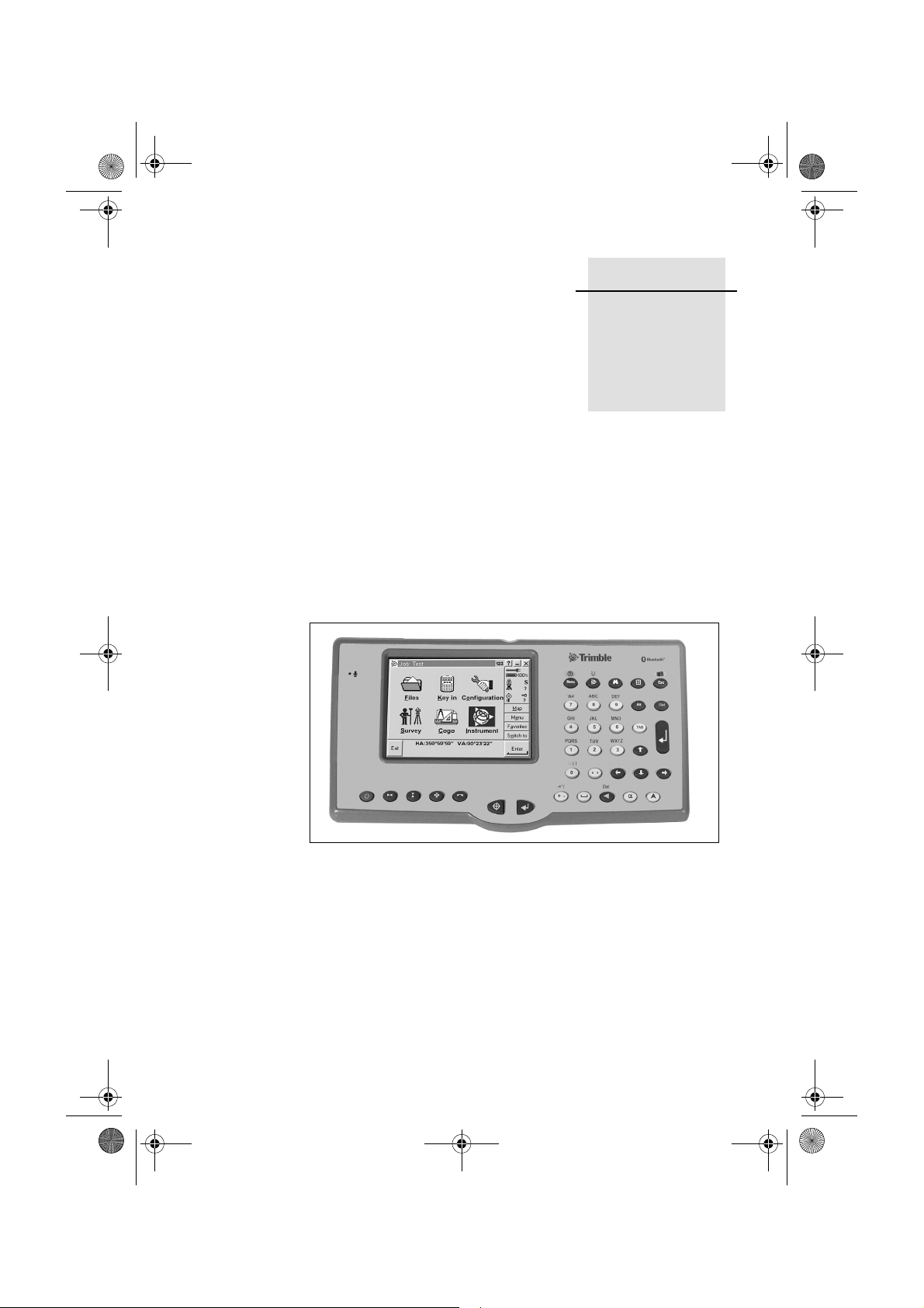
Trimble Survey Controller is designed to run on the ACU
controller. This chapter describes the controller and how to use it.
Figure 1.1 shows the front of the ACU and its keys.
CHAPTER
1
Figure 1.1 The ACU controller – front view
Page 4
Penguin_GSG.book Page 2 Thursday, July 25, 2002 9:27 AM
The ACU Controller
1.1 Attaching the ACU
C
Warning – Switch off the ACU when attaching it to the holde r or when
changing the batteries in the holder with the ACU attached.
Otherwise, the on/off status of the ACU and the holder may become
unsyncronised.
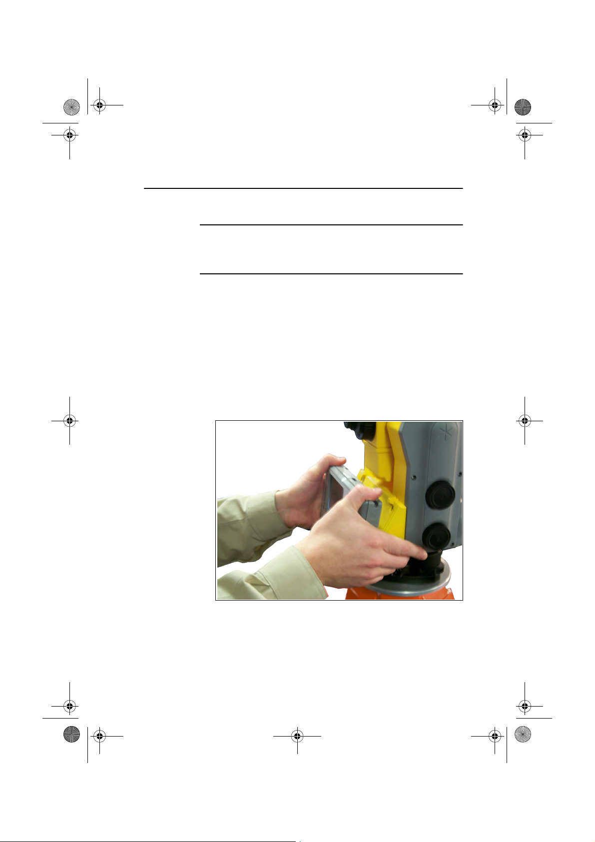
To attach the ACU:
1. Hold the controller with both hands.
2. Fit the groove on the back of the controller over the lower
lip on the front of the holder.
3. Press down and rest the back of the controller flat against
the holder.
4. Gently release downward pressure and guide the
controller so that the teeth on the front of the holder click
into the notches on top of the controller.
Figure 1.2 shows how to attach the ACU to the holder.
Figure 1.2 Attaching the ACU
2 Trimble Survey Controller Getting Started Guide
Page 5
Penguin_GSG.book Page 3 Thursday, July 25, 2002 9:27 AM
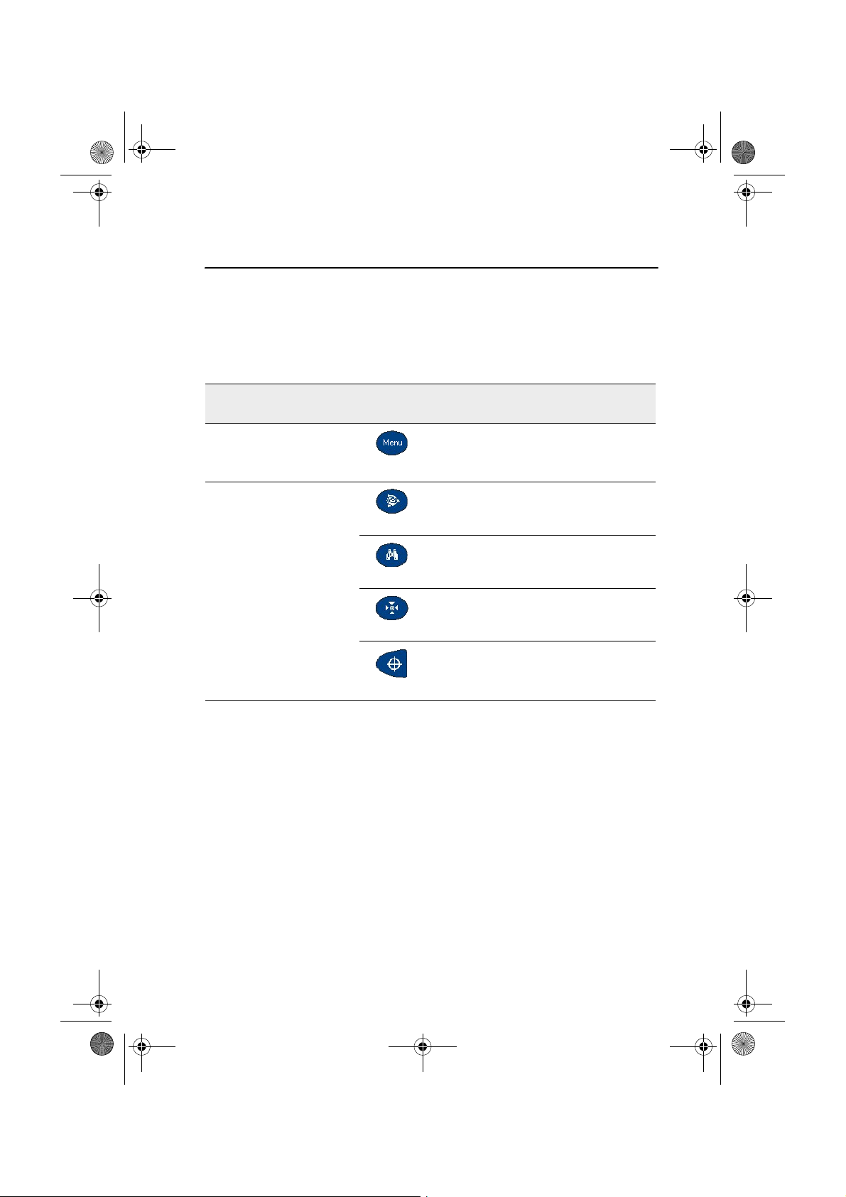
1.2 ACU Function Keys
Table 1.1 describes Trimble Survey Controller functions that are
associated with the ACU icons.
Table 1.1 ACU function keys
On this instrument or
receiver ...
tap ... to ...
The ACU Controller
Conventional
or
GPS
Conventional
(with Autolock™)
access the main Trimble Survey
Controller menu
access the Trimble function screen
switch Autolock on and start a search
switch Autolock on or off
take a measurement
Trimble Survey Controller Getting Started Guide 3
Page 6

Penguin_GSG.book Page 4 Thursday, July 25, 2002 9:27 AM
The ACU Controller
Table 1.1 ACU function keys (Continued)
On this instrument or
receiver ...
tap ... to ...
turn the instrument horizontally to the
current point name or stakeout location
turn the instrument vertically to the
current point name or stakeout location
Conventional
(with servos)
Conventional (3600)
turn the instrument horizontally and
vertically to the current point name or
stakeout location
change face
take a measurement
activate the first softkey (F1)
activate the second softkey (F2)
activate the third softkey (F3)
activate the fourth softkey (F4)
take a measurement
4 Trimble Survey Controller Getting Started Guide
Page 7

Penguin_GSG.book Page 5 Thursday, July 25, 2002 9:27 AM
Table 1.1 ACU function keys (Continued)
On this instrument or
receiver ...
tap ... to ...
The ACU Controller
access the Position dialog
access the Satellites dialog
activate the first softkey (F1)
GPS
activate the second softkey (F2)
activate the third softkey (F3)
activate the fourth softkey (F4)
activate the
Enter button
Trimble Survey Controller Getting Started Guide 5
Page 8

Penguin_GSG.book Page 6 Thursday, July 25, 2002 9:27 AM
The ACU Controller
1.3 Power Supply
Under normal operation, the ACU draws power from the device it
is attached to or from one of the following external batteries:
• 12V NiMH
• 7.4 Lithium-ion
The ACU has an internal, rechargeable 4.8 volt 600 mAh NimH
battery. If power is lost during operation the ACU automatically
switches over to this battery, which provides approximately two
hours running time when fully charged.
The ACU holder has dual 7.4V 1.8Ah lithium-ion batteries.
When fully charged, these provide approximately 15 hours
running time to the ACU through the 7-pin backplane.
The TSCe is supplied with a rechargeable 4.8 volt 3800 mAh
NiMH battery, which provides over 30 hours of running time
when fully charged.
1.3.1 Charging the batteries
The internal battery of the ACU is automatically charged when
the controller is connected to an external power supply.
To charge the internal battery:
• Connect the AC adaptor from the ACU 4-pin Hirose port to
the mains power supply.
The ACU detects the following low power levels from the
external batteries:
• 10 volts (12V NiMH battery)
• 6 volts (Lithium-ion battery)
The ACU alerts you when power level is critically low. If this
happens, turn the equipment off and change the external battery.
Otherwise, the ACU will switch over to its internal battery.
6 Trimble Survey Controller Getting Started Guide
Page 9

Penguin_GSG.book Page 7 Thursday, July 25, 2002 9:27 AM
The TSCe incorporates a quick circuit that recharges its internal
NiMH battery to 90% capacity in approximately one hour. To
charge the battery, use one of the following methods:
– Connect the AC adaptor to a mains power supply, with the
Multiport adaptor (part number RGR-MULTIADPT) plugged
into the 26-pin port (COM 2) on the TSCe.
– Connect the O-shell to O-shell lemo (PN 31288-02) to Port 1
on the receiver (running on mains power)
– Connect the O-shell lemo from the OSMII to the O-shell lemo
on the TSCe.
The control unit monitors the battery while it is charging. To
turn off the display, press the _ key.
Before using the TSCe on battery power alone, charge the
battery for a minimum of two hours.
The ACU Controller
1.3.2 Battery replacement
C
Warning – Do not attempt to change the battery or you may seriously
damage the ACU. Contact your local distributor.
Contact your local distributor for a replacement battery.
1.4 Screen
The ACU reflective LCD screen can be viewed easily in direct
sunlight or in overcast conditions. It also incorporates a passive
touch interface for navigation. Tap elements on the display screen
with a stylus or your finger.
Trimble Survey Controller Getting Started Guide 7
Page 10

Penguin_GSG.book Page 8 Thursday, July 25, 2002 9:27 AM
The ACU Controller
1.4.1 Recalibrating the touch screen
If the touch screen does not respond properly when you tap it,
recalibrate it as follows:
1. Tap and select Settings / Control Panel / Stylus.
The Stylus Properties dialog appears.
2. In the Calibration tab, tap [Recalibrate].
3. Follow the prompts.
1.4.2 Disabling the touch screen
To clean the ACU screen during a survey, press [Ctrl]+ (the
alpha key) then [1] four times (to access “S”) to disable it. This
locks the screen and keypad, except for the [Esc] key.
To disable the TSCe screen, press [Ctrl]+[S].
To enable the touch screen and keypad again, press [Esc].
1.5 Backlight
To modify the backlight settings:
•Select Display / Backlight from the Control Panel.
•If the Auto on option is disabled, press ~ and .
Press ~ and to switch between these backlight modes:
• screen and keyboard on
• screen only on
• screen and keyboard off
8 Trimble Survey Controller Getting Started Guide
Page 11

Penguin_GSG.book Page 9 Thursday, July 25, 2002 9:27 AM
1.6 Clock
To change time and date settings on the ACU:
1. Tap and select Settings / Control Panel /
Date/Time.
The Date/Time Properties dialog appears.
2. Change the date and time as required. Press = to
accept the new settings or E to cancel.
Note – When you connect the ACU to a GPS receiver or to your
PC using Microsoft ActiveSync, the date and time are
automatically updated.
1.7 Storage Card
The ACU has a built-in storage card for your data and programs.
This appears in the Windows CE files system as the \Disk folder.
Note – The system maintains several special files on the card,
such as nk.bin and ranger.reg, which contain information crucial
to the correct operation of the ACU. Dir ectly modifying these files
may result in the ACU failing to operate correctly.
The ACU Controller
1.7.1 Safeguarding data
Back up your work regularly using Microsoft ActiveSync or the
Trimble Data Transfer utility. For more information, see
Chapter 4, Data Transfer.
1.8 Rebooting
If the ACU fails to respond to keystrokes, then perform one of the
following resets, which shut down the hardware and restart the
Trimble Survey Controller software.
1.8.1 Soft reset (warm boot)
This method retains all data.
Trimble Survey Controller Getting Started Guide 9
Page 12

Penguin_GSG.book Page 10 Thursday, July 25, 2002 9:27 AM
The ACU Controller
To perform a soft reset:
• Hold down ~ and C, while you press and release .
The ACU resets to the default Microsoft Windows desktop view.
To warm boot the TSCe, hold down ~ and C, while you
press and release _.
1.8.2 Hard reset (cold boot)
This method retains any data on the built-in storage card (the
\Disk folder). However, a hard reset clears the contents of the
RAM memory, including any desktop shortcuts that you have
created.
To perform a hard reset:
1. Hold down _.
After approximately 5 seconds, a countdown timer
appears, indicating that the controller will reset.
2. Continue to hold _ for a further 5 seconds, then release.
The controller briefly displays the boot screen and then resets to
the default Microsoft Windows desktop view.
1.9 Caring for the unit
Trimble recommends the following to maintain your ACU during
everyday use, and to prevent potential physical damage or data
loss.
Operating temperature: –20° C to +55° C
Storage temperature: –30° C to +70° C
Do not expose the TSCe to temperatures below –20° C (–4° F)
or above +60° C (140° F). Do not leave it in direct sunlight for
extended periods of time.
10 Trimble Survey Controller Getting Started Guide
Page 13

Penguin_GSG.book Page 11 Thursday, July 25, 2002 9:27 AM
Shock
The TSCe is designed to withstand a MIL-STD-810E drop.
However, impact or pressure on the display screen may cause it
to crack. Protect the display from impact, pressure, or abrasive
substances.
Environment – The ACU is designed to withstand driving rain
and dust.
The TSCe is designed to be immersible in up to one meter of
water, for up to one hour.
Cleaning the case – Clean the controller with a soft cloth
dampened with clean water or with water containing a mild
detergent. If the keyboard has dirt or grime on it, use compressed
air or a vacuum cleaner, or gently rinse it with clean water.
Care of the touch screen – Clean the touch screen with a soft
cloth dampened with clean water or glass cleaner. Do not apply
any cleaner directly to the screen. Apply the cleaner to the soft
cloth and then gently wipe the screen.
Note – Do not use abrasive cleaners.
Applying a screen protector – Use a screen protector to help
keep the touch screen clean and protected. Clean the screen
thoroughly and leave it slightly wet. Peel the backing from the
screen protector and then apply the protector to the screen. Use a
soft cloth to squeeze the excess water and air from under the
screen protector.
The ACU Controller
Trimble Survey Controller Getting Started Guide 11
Page 14

Penguin_GSG.book Page 12 Thursday, July 25, 2002 9:27 AM
The ACU Controller
12 Trimble Survey Controller Getting Started Guide
 Loading...