

Page 1

Trimble 5600 Series
www.trimble.com
Page 2

Page 3

Trimble 5600 Series
User Guide
F
Version 04.00
Part Number 571 702 011
December 2002
Page 4

Corporate Office
Trimble Navigation Limited
5475 Kellenburger Road
Dayton, Ohio 45424-1099
U.S.A.
800-538-7800 (Toll Free in U.S.A.)
+1-937-233-8921 Phone
+1-937-233-9441 Fax
www.trimble.com
Copyright and Trademarks
Copyright © 2001-2002, Trimble Navigation
Limited. All rights reserved. Geodimeter,
Tracklight and Trimble are trademarks of
Trimble Navigation Limited, registered in the
United States Patent and Trademark Office.
The Globe & Triangle logo and Autolock are
trademarks of Trimble Navigation Limited.
All other trademarks are the property of their
respective owners.
Release Notice
This is the December 2002 release version 04.00
of the Trimble 5600-series User Guide, part
number 571 702 011. It applies to the Trimble
5600-series total station.
The following limited warranties give you
specific legal rights. You may have others, which
vary from state/jurisdiction to state/jurisdiction.
Hardware Limited Warranty
Trimble Navigation Limited warrants that this
hardware product (the “Product”) will perform
substantially in accordance with published
specifications and be substantially free of defects
in material and workmanship for a period of one
(1) year starting from the date of delivery. The
warranty set forth in this paragraph shall not
apply to software products.
Software License, Limited Warranty
This Trimble software pr oduct, whether provided
as a stand-alone computer software product, built
into hardware circuitry as firmware, embedded
in flash memory, or stored on magnetic or other
media, (the “Software”) is licensed and not sold,
and its use is governed by the terms of the
relevant End User License Agreement (“EULA”)
included with the Software. In the absence of a
separate EULA included with the Software
providing different limited warranty terms,
exclusions and limitations, the following terms
and conditions shall apply. T rimble warrants that
this Trimble Software product will substantially
conform to Trimble’s applicable published
specifications for the Software for a period of
ninety (90) days, starting from the date of
delivery.
Warranty Remedies
Trimble's sole liability and your exclusive
remedy under the warranties set forth above shall
be, at Trimble’s option, to repair or replace any
Product or Software that fails to conform to such
warranty ("Nonconforming Product") or refund
the purchase price paid by you for any such
Nonconforming Product, upon your return of any
Nonconforming Product to Trimble in
accordance with Trimble’s standard return
material authorization procedures.
Warranty Exclusions and Disclaimer
These warranties shall be applied only in the
event and to the extent that the Products and
Software are properly and correctly installed,
configured, interfaced, maintained, stored, and
operated in accordance with Trimble's relevan t
operator's manual and specifications, and; (ii) the
Products and Software are not modified or
misused. The preceding warranties shall not
apply to, and Trimble shall not be responsible for
defects or performance problems resulting from
(i) the combination or utilization of the Product
or Software with hardware or software products,
information, data, systems, interfacing or devices
not made, supplied or specified by Trimble; (ii)
the operation of the Product or Software under
any specification other than, or in addition to,
Trimble's standard specifications for its products;
(iii) the unauthorized modification or use of the
Product or Software; (iv) damage caused by
accident, lightning or other electrical discharge,
fresh or salt water immersion or spray; or (v)
normal wear and tear on consumable parts (e.g.,
batteries). Trimble does not warrant or gua rantee
the results obtained through the use of the
Product.
THE WARRANTIES ABOVE STATE TRIMBLE'S
ENTIRE LIABILITY, AND YOUR EXCLUSIVE
REMEDIES, RELATING TO PERFORMANCE OF
THE PRODUCTS AND SOFTWARE. EXCEPT AS
OTHERWISE EXPRESSLY PROVIDED HEREIN,
THE PRODUCTS, SOFTWARE, AND
ACCOMPANYING DOCUMENTATION AND
MATERIALS ARE PROVIDED “AS-IS” AND
WITHOUT EXPRESS OR IMPLIED WARRANTY
OF ANY KIND BY EITHER TRIMBLE
NAVIGATION LIMITED OR ANYONE WHO HAS
BEEN INVOLVED IN ITS CREATION,
PRODUCTION, INSTALLATION, OR
DISTRIBUTION INCLUDING, BUT NOT
LIMITED TO, THE IMPLIED WARRANTIES OF
MERCHANTABILITY AND FITNESS FOR A
PARTICULAR PURPOSE, TITLE, AND
NONINFRINGEMENT. THE STATED EXPRESS
WARRANTIES ARE IN LIEU OF ALL
OBLIGATIONS OR LIABILITIES ON THE
PART OF TRIMBLE ARISING OUT OF, OR
IN CONNECTION WITH, ANY PRODUCTS
OR SOFTWARE. SOME STATES AND
JURISDICTIONS DO NOT ALLOW
LIMITATIONS ON DURATION OR THE
EXCLUSION OF AN IMPLIED
WARRANTY, SO THE ABOVE
LIMITATION MAY NOT APPLY TO YOU.
Page 5

TRIMBLE NAVIGATION LIMITED IS NOT
RESPONSIBLE FOR THE OPERATION OR
FAILURE OF OPERAT ION OF GPS
SATELLITES OR THE AVAILABILITY OF
GPS SATELLITE SIGNALS.
Limitation of Liability
TRIMBLE’S ENTIRE LIABILITY UNDER ANY
PROVISION HEREIN SHALL BE LIMITED TO
THE AMOUNT PAID BY YOU FOR THE
PRODUCT OR SOFTWARE LICENSE. TO THE
MAXIMUM EXTENT PERMITTED BY
APPLICABLE LAW, IN NO EVENT SHALL
TRIMBLE OR ITS SUPPLIERS BE LIABLE FOR
ANY INDIRECT, SPECIAL, INCIDENTAL OR
CONSEQUENTIAL DAMAGES WHATSOEVER
UNDER ANY CIRCUMSTANCE OR LEGAL
THEORY RELATING IN ANY WAY TO THE
PRODUCTS, SOFTWARE AND
ACCOMPANYING DOCUMENTATION AND
MATERIALS, (INCLUDING, WITHOUT
LIMITATION, DAMAGES FOR LOSS OF
BUSINESS PROFITS, BUSINESS
INTERRUPTION, LOSS OF BUSINESS
INFORMATION, OR ANY OTHER PECUNIARY
LOSS), REGARDLESS WHETHER TRIMBLE HAS
BEEN ADVISED OF THE POSSIBILITY OF ANY
SUCH LOSS AND REGARDLESS OF THE
COURSE OF DEALING WHICH DEVELOPS OR
HAS DEVELOPED BETWEEN YOU AND
TRIMBLE. BECAUSE SOME STATES AND
JURISDICTIONS DO NOT ALLOW THE
EXCLUSION OR LIMITATION OF LIABILITY
FOR CONSEQUENTIAL OR INCIDENTAL
DAMAGES, THE ABOVE LIMITATION MAY
NOT APPLY TO YOU.
NOT WITHST ANDING THE ABOVE, IF YOU
PURCHASED THIS PRODUCT OR
SOFTWARE IN THE EUROPEAN UNION,
THE ABOVE WARRANTY PROVISIONS
MAY NOT APPLY. PLEASE CONTACT
YOUR DEALER FOR APPLICABLE
WARRANTY INFORMATION.
Notices
Class B Statement – Notice to Users. This
equipment has been tested and found to comply
with the limits for a Class B digital device,
pursuant to Part 15 of the FCC rules. These
limits are designed to provide reasonable
protection against harmful interference in a
residential installation. This equipment
generates, uses, and can radiate radio frequency
energy and, if not installed and used in
accordance with the instructions, may cause
harmful interference to radio communication.
However, there is no guarantee that interference
will not occur in a particular installation. If this
equipment does cause harmful interference to
radio or television reception, which can be
determined by turning the equipment off and on,
the user is encouraged to try to correct the
interference by one or more of the following
measures:
– Reorient or relocate the receiving antenna.
– Increase the separation between the equipment
and the receiver.
– Connect the equipment into an outlet on a
circuit different from that to which the
receiver is connected.
– Consult the dealer or an experienced radio/TV
technician for help.
Changes and modifications not expressly
approved by the manufacturer or registrant of
this equipment can void your authority to operate
this equipment under Federal Communications
Commission rules.
Using Georadio:
Radio equipment used complies with the
Essential requirements of the R&TTE Directive
1999/5/EC
This equipment complies with the regulation of
C-Tick
N 324
Page 6

Page 7

Laser Safety Information
Before using the instrument, make sure that you understand this
User Guide, as well as all equipment and jobsite safety
requirements.
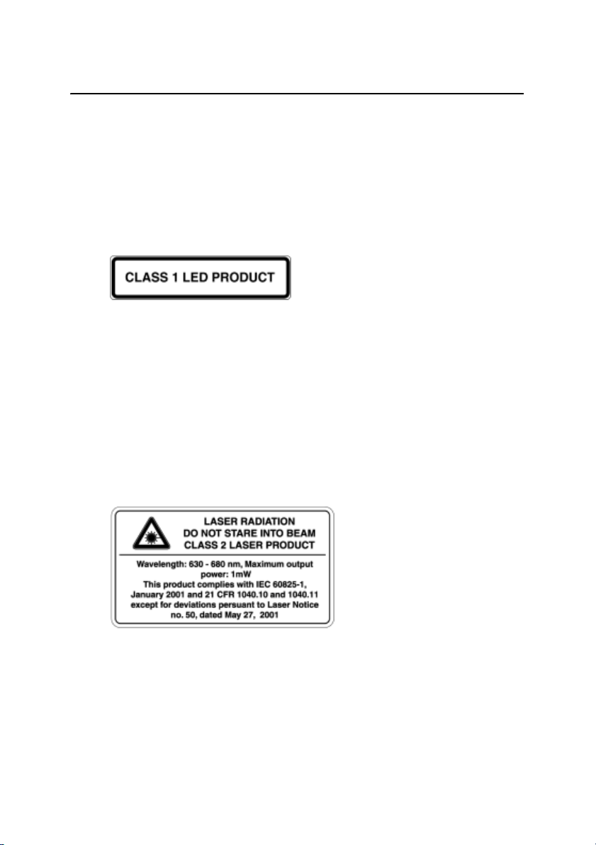
Laser Safety
This equipment has been tested and found to comply with IEC
60825-1 January 2001, 21 CFR 1040.10 and 1040.11 except for
deviations persuant to Laser Notice no. 50, dated May 27, 2001.
Use of controls or adjustments or performance of procedures
C
other than those specified herein may result in hazardous LED or
Laser radiation exposure. As with any bright light source, such as
the sun, electric welding arcs or arc lamps, common sense
applies. DO NOT look into the laser aperture when the laser is on.
For further information regarding safe use of lasers, refer to the
IEC standard 60825-1 January 2001.
Queries
Address any questions you may have about laser safety to:
Trimble
5475 Kellenburger Road
Dayton, OH U.S.A. 45424-1099
Attention: Laser Safety Officer, Quality Assurance Group
Phone (937) 233-8921 ext 824 or (800) 538-7800
Fax (937) 233-9661
vii
Page 8
Laser Safety Information
Trimble 5600 & ATS
The Trimble 5600 & ATS contains one light source:
A LED for the distance measuring function operating at 850 nm
(infrared, non-visible light), with a beam divergence of 1.6 mrad
and an output power of < 0.44 mW, laser CLASS 1.
Trimble 5600 DR Standard
The Trimble 5600 DR Standard contains one light source:
A laser diode for both distance measuring and laser pointer
function operating at 660 nm (visible light), with a beam
divergence of 0.4 x 0.8 mrad and an output power of < 1 mW,
laser CLASS 2.
viii
Page 9
Laser Safety Information
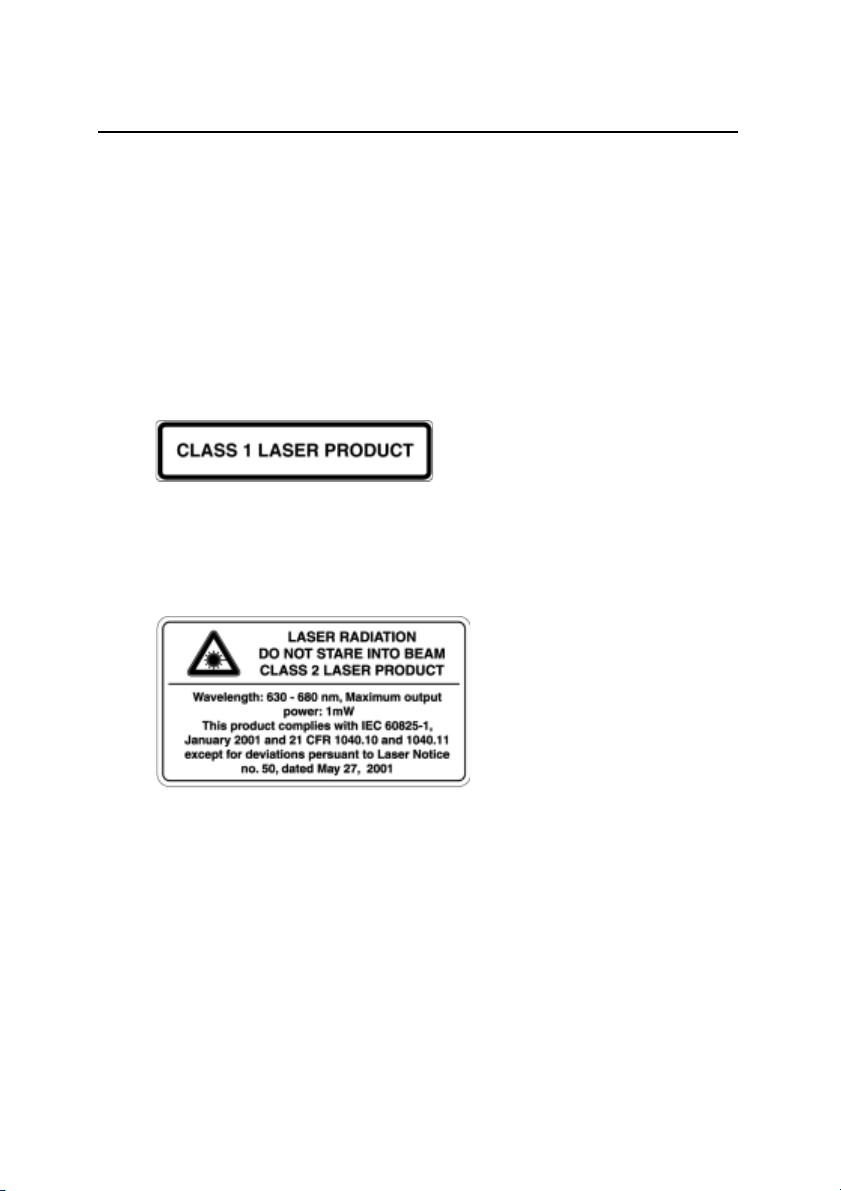
Trimble 5600 DR 200+ & DR 300+ (and
optional Laser Pointer)
The Trimble 5600 DR 200+ & DR 300+ (with Laser Pointer)
may contain two light sources:
A laser diode for the distance measuring function operating at 850
nm (infrared, non-visible light), with a beam divergence of 0.4 x
0.8 mrad and an output power of < 0.48 mW, laser CLASS 1.
As an option, a Laser Pointer operating at 635
light), with a beam divergence of 0.3 mrad and an output power of
< 1 mW, laser CLASS 2.
– 670 nm (visible
ix
Page 10

Laser Safety Information
x
Page 11

Welcome to Trimble 5600 Series
Comments about this manual ..........................................B
Glossary of terms used with the System ......................... B
1 Introduction
Unpacking & Inspection................................................. 1-3
Inspection......................................................................1-3
Aiming at the target.......................................................1-3
Controls .........................................................................1-4
Pre-Measurement.......................................................... 1-6
Connecting the external battery to the instrument........1-6
The Side Cover..............................................................1-7
The Central Unit.............................................................1-8
Additional Control Units...............................................1-9
Laser and LED Information.......................................... 1-10
Trimble 5600-series & ATS........................................1-10
Trimble 5600 DR Standard -series..............................1-11
Trimble 5600 DR 200+ & DR 300+ -series................1-13
Table of Contents
2 Surveying methods
In general.......................................................................2-2
Conventional surveying with servo ..............................2-2
Autolock........................................................................2-3
Robotic Surveying ........................... .............................2-3
Conventional surveying with Autolock........................... 2-4
Important information when measuring with high accuracy
(and using the instrument’s Tracker)................... 2-4
Aiming ..........................................................................2-5
Robotic Surveying..........................................................2-6
Page 12

Table of Contents
Important information when measuring with high accuracy
(and using the instrument’s Tracker)................... 2-6
Equipment.....................................................................2-7
Radio communication............................. ......................2-7
3 Angle Measurement System
Overview........................................................................3-3
The Angle Measuring Technique ...................................3-3
Dual Axis Compensator................. ............................... 3-3
Correction for Collimation Errors............. ....................3-4
Correction for Trunnion Axis Tilt.................................3-4
Single-Face Angle Measurement..................................3-5
Two-Face Angle Measurement......................................3-5
4 Distance Measurement System
Overview........................................................................4-3
Distance Measurement..................................................4-3
Automatic control of signal level..................................4-4
Measurement range and accuracy.................................4-4
5Servo
Overview........................................................................5-2
Servo controls................................................................5-2
Motion knobs ................................................................5-2
6 Tracklight
Overview........................................................................6-3
Changing the bulb...... .................................... ...............6-4
Page 13

7 Tracker
Overview........................................................................7-2
8 Beam adjustment
Laser beam DR Standard.............................................. 8-2
Overview.......................................................................8-2
Alignment .....................................................................8-2
Adjustment....................................................................8-4
Laser Pointer DR 200+ & DR 300+ ...............................8-6
Overview.......................................................................8-6
Alignment .....................................................................8-6
Adjustment....................................................................8-7
9Radio
Overview........................................................................9-3
Radio controls................................................................9-3
Select radio channel................................ ......................9-3
Station address ............. .................................... .............9-3
Radio license.............. ...................................................9-4
Range ............................................................................9-4
Table of Contents
10 Power Supply
Batteries....................................................................... 10-2
Internal Battery unit (Central unit) .............................10-2
External Battery/Radio Battery...................................10-2
Single Adapter ............................................................10-3
Multi Adapter............................. ................................. 10-3
Battery Cables.............................................................10-4
Battery Charging.......................................................... 10-5
Single Charger (571 906 214).....................................10-5
Super Charger (571 906 145)......................................10-5
Page 14

Table of Contents
Power Unit (571 906 146)...........................................10-6
About charging NiMH (and NiCd) batteries...............10-6
Bat Low....................................................................... 10-6
11 Care & Maintenance
Overview...................................................................... 11-2
Cleaning......................................................................11-3
Condensation...............................................................11-3
Packing for Transport..................................................11-3
12 Card Memory
Overview...................................................................... 12-2
Installation.................................................................... 12-2
How to connect to a Trimble 5600 Series instrument.12-2
How to insert the memory card...................................12-5
Memory Card............................................................... 12-8
Capacity ...................................................................... 12-8
Memory structure........................................................ 12-8
Handling hints.............................................................12-9
13 RMT Remote Targets
In General.................................................................... 13-2
RMT 602...................................................................... 13-3
RMT 606...................................................................... 13-4
RMT 600 TS ................................................................ 13-5
RMT Super Multi Channel ........................................... 13-7
RMT SLR..................................................................... 13-8
14 Machine Control & Guidance
Start up procedures......................................................14-2
Page 15

Table of Contents
Georadio and Machine Control...................................14-3
Setting of radio channel and addresses.......................14-3
Remote operation and station establishment...............14-3
Auto search .................................................................14-4
Distance meter calibration .......................................... 14-5
RMT ATS Multi Channel........................... ... .............14-6
Page 16

Table of Contents
Page 17

Welcome to Trimble 5600 Series
Trimble AB, has since the release of Geodimeter® System
400 presented a large number of inventions within the
surveying field; the tracklight
keyboard, servo, one-person total station etc.
In 1994 we introduced the first flexible total station,
Geodimeter System 600, which made it possible for the
user to physically tailor his or her total station to his/her
needs. In 1998 Geodimeter System 600 Pro was introduced
which included a number of technical improvements such
as a faster CPU and faster and smoother servo positioning.
The first introduction in 2000 was the Geodimeter 600
ATS. An instrument that can also be used for machine
control.
To improve productivity of the Geodimeter System 600
even further, a new Direct Reflex and servo driven model,
DR200+, was launched the same year.
®
, the alpha-numeric
The Trimble 5600 series was introduced in 2001 and in
2002 came the introduction of DR Standard and DR300+.
The system includes, of course, all the features that are
typical for Geodimeter, such as servo-assisted drive
(optional), numeric or alpha-numeric control units
(keyboards), tracklight, tracker (optional), radio side cover
(optional) and RS-232C communication.
- A - Trimble 5600-series
Page 18

Comments about this manual
If you or your colleagues have any comments on this
manual, we would be grateful to hear from you. Please
write to:
Trimble AB
Technical information dept.
Box 64
SE-182 11 DANDERYD
Sweden
Or send an e-mail to: info@trimble.se
Glossary of terms used with the System (Only with
GDM CU)
Area File: A file in the memory device that holds
known coordinates (Pno, N, E etc.) or
Roadline data.
A/M-key: Aim/Measure button. Initiates a
measurement and controls search and
remote measurements.
D: Accurate measurement with mean value
calc.
dH & dV: These values represents the collimation
errors. When performing D-bar
measurements in two faces these errors do
not affect the accuracy of the measurement
(HA, VA). If the values differs a lot from 0
it is recommended that you perform a test
measurement (MNU5).
Trimble 5600-series - B -
Page 19

Free Station: Also known as Resection. Location of the
total station by measuring distance and/or
angles to 2 or up to 8 points.
FSTD: Fast Standard measurement, with A/M.
IH: Instrument height over the point.
Job File: A file in a the memory device that holds
data collected in the field. This file can
consist of any data.
Logon: Entering Job file and memory unit when
designing a U.D.S with program 40.
Offset: Length offset to measured slope distance.
Prism const: The prism’s length offset from the
0-constant.
Ref. Obj: Reference Object, also back sight.
REG-key: The register key. This stores data in the
data collector.
RMT: Remote Measuring Target. The special
prism used when performing robotics
surveying (or remote surveying with auto
lock), i.e.carrying out one-person
measurements.
R.O.E: Remote Object Elevation.
RPU: Remote Positioning Unit. The rod half of
the system when performing remote or
robotic surveying.
SH: Signal height.
STD: Standard measurement, with A/M.
- C - Trimble 5600-series
Page 20
TRK: Tracking measurement, automatic and
continuous measurement.
U.D.S.: User Defined Sequence. A program
designed by the user determining what is
collected, its order of collection and how it
is displayed on the screen.
SH
dELE
IH
ELE
Trimble 5600-series - D -
Point to set out
Page 21

1Introduction
Unpacking & Inspection ....................................................... 1-3
Inspection........................................................................ 1-3
Controls................................................................................ 1-4
The Side Cover....................................................................1-7
The Central Unit................................................................... 1-8
Additional Control Units........................................................1-9
Additional Control Units ..................................................1-9
Laser and LED Information................................................1-10
Trimble 5600-series & ATS........................................... 1-10
Trimble 5600 DR Standard -series................................ 1-11
Trimble 5600 DR 200+ & DR 300+ -series................... 1-13
CHAPTER
1
Page 22
1 Introduction
Figure 1.1 Trimble 5600 Series
1-2 Trimble 5600-series
Page 23

Unpacking & Inspection
Before we begin to describe the operating procedure of
your Trimble instrument, it is first necessary to acquaint
yourself with the equipment received:
• Instrument Unit
• Transport case
• Tribrach
• Rain cover
• Reflective sight marks (stick-on)
• User Manual
• Tool kit
Note – Some equipment is market dependent
Inspection
Inspect the shipping container. If it is received in poor
condition, examine the equipment for visible damage. If
damage is found, immediately notify the carrier and the
Trimble sales representative. Keep the container and
packing material for the carrier’s inspection.
Unpacking & Inspection
Trimble 5600-series 1-3
Page 24
1 Introduction
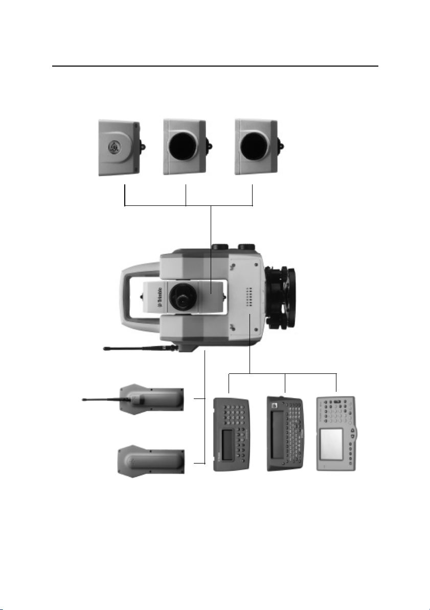
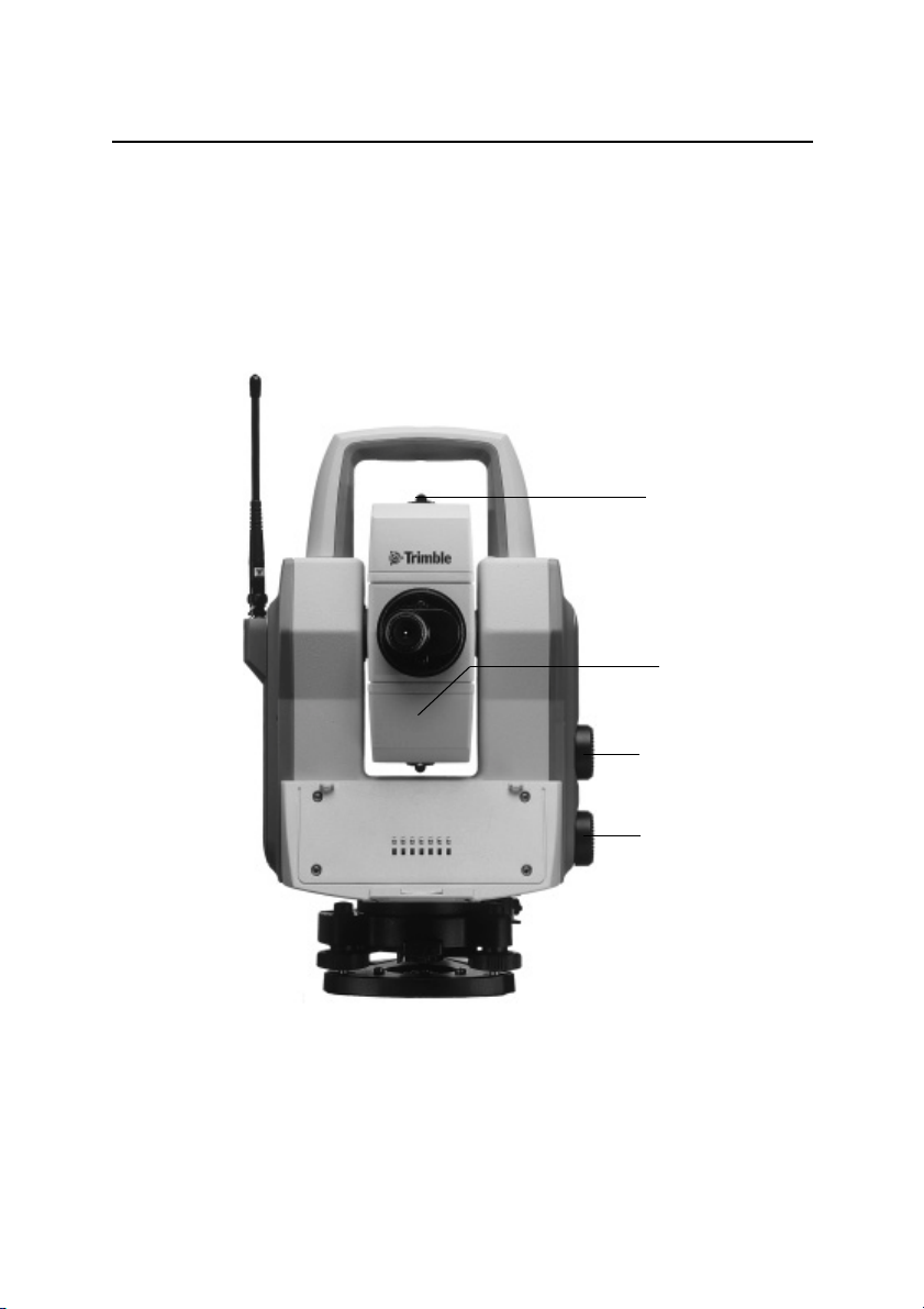
Controls
Here you find a list of the controls of your instrument.
Please take at moment to familiarize your self with the
names and the locations of the controls.
Coarse sight
Central unit
(Battery,Tracklight or Tracker)
Vertical motion
servo control
Figure 1.2 Trimble 5600 Series shown from the operator side
1-4 Trimble 5600-series
Horizontal motion
servo control
(back), a central unit, a central battery unit and a
radio side cover.
Page 25
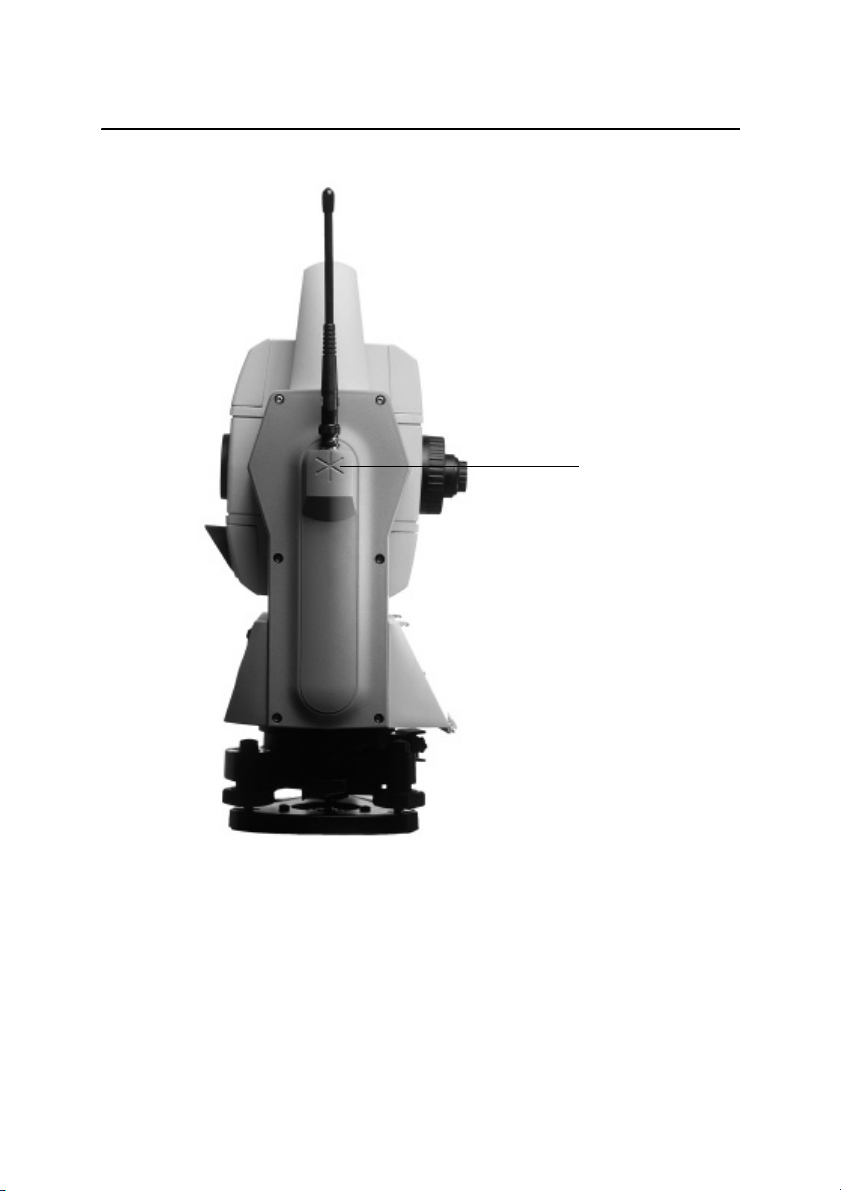
Controls
Prism symbol
(which marks the instrument
height (IH), also on the
opposite side cover)
Figure 1.3 Trimble 5600 Series seen from the side, equipped
with a central tracker unit and a radio side cover.
Trimble 5600-series 1-5
Page 26
1 Introduction
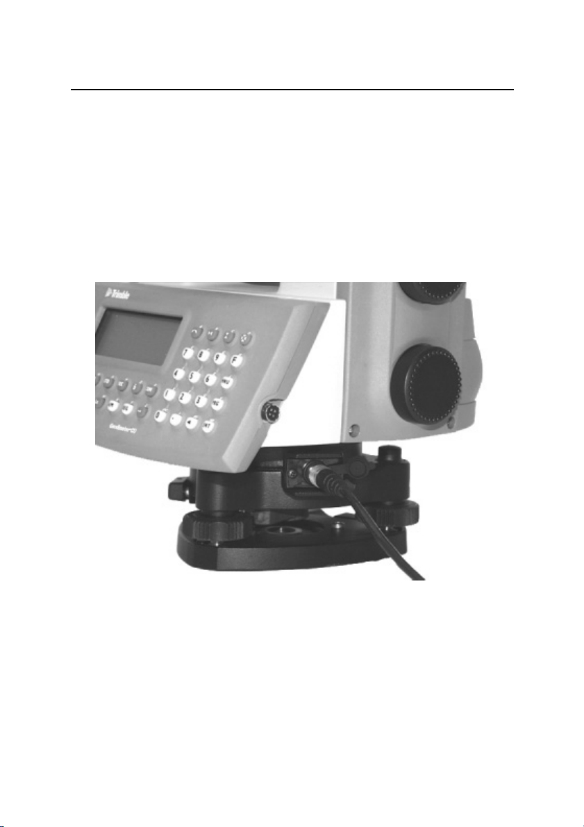
Pre-Measurement
Connecting the external battery to the instrument
The instrument can be equipped with an external battery
that is connected to the instrument via the battery cable.
The cable is to be connected to the connector on the
instrument resp. battery as shown in the picture below .
Figure 1.4 Connecting the external battery to the instrument.
1-6 Trimble 5600-series
Page 27
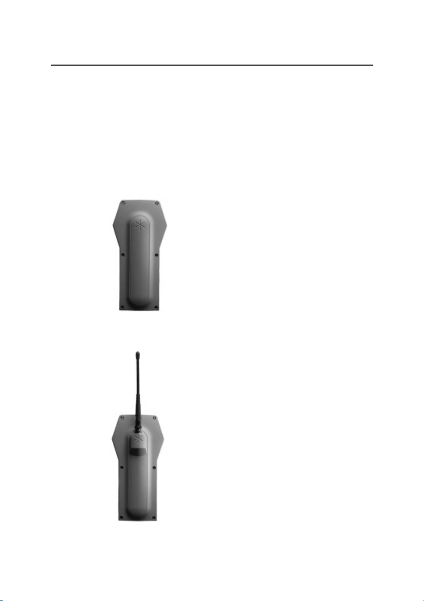
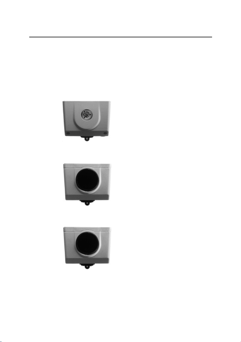
The Side Cover
The instrument can be configured with two different side
covers; a plain or a radio unit cover . It is possible to change
side cover if you need another type, but it has to be done at
a Trimble authorized service center.
Plain Cover
Radio Unit Cover
The Side Cover
The radio unit cover is needed when you
wish to use the instrument for remote
surveying or robotic surveying (one-person
total station), see chapter 1.5.
Trimble 5600-series 1-7
Page 28
1 Introduction
The Central Unit
The central unit can be configured with the internal battery,
the tracklight or the tracker unit. You can change between
battery unit and tracklight by yourself, but the tracker unit
must be installed at a Trimble authorized service center.
Internal battery
The internal battery gives you
2 hours of continuous use.
Tracklight
Tracklight is a visible guide
light which is an aid to the
rodman e.g. when setting out.
1-8 Trimble 5600-series
Tracker (only for servo
instruments)
The tracker has control of the
instruments when using the
system for robotic surveying
(one-person system) or in
Autolock™ mode.
Page 29

Additional Control Units
With Trimble 5600 Series you can work with two control
units attached at the same time: one at the back of the
instrument that serves as a master control unit and one at
the front that serves as a slave unit.
Having two control units attached at the same time can be
useful having in mind that they also contain internal
memories.
The control unit at the front can also be very useful when
measuring in two faces when you want to keep control of
the point to measure in face 2.
The Central Unit
Trimble 5600-series 1-9
Page 30
1 Introduction
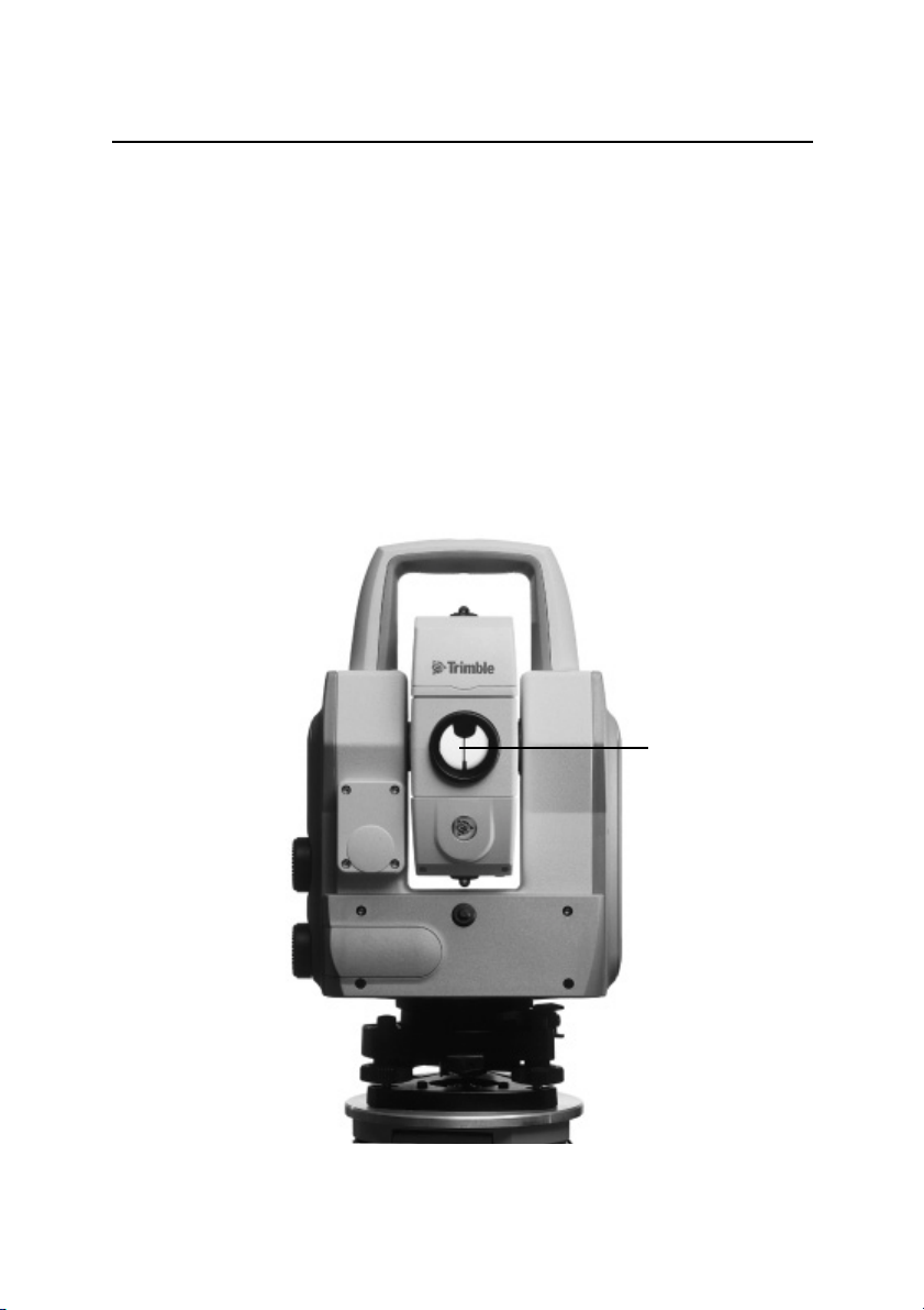
Laser and LED Information
Trimble 5600-series & ATS
The Trimble 5600 Series & ATS instruments have been
tested and complies with the regulations for a Class 1 LED
product. See the laser safety information on the fist pages of
this manual. This means that no special precautions are
required for safe operation as long as the instrument is not
opened and the diode uncovered. In the figure below the
LED aperture is pointed out.
Distance
Measuring LED
aperture
Figure 1.5 LED aperture
1-10 Trimble 5600-series
Page 31

Laser and LED Information
g
Trimble 5600 DR Standard -series
The Trimble 5600 DR Standard Series instrument has been
tested and complies with the regulations for a Class 2 Laser
product. See laser safety information on the first pages of
this manual.
Distance measurin
and laser pointer
aperture
Figure 1.6 Laser apertures
Trimble 5600-series 1-11
Page 32

1 Introduction
l
The laser warning label is located on the side of the distance
measuring unit as shown below
Laser
Warning
Figure 1.7 Laser warning label location
labe
Figure 1.8 Laser warning label
1-12 Trimble 5600-series
Page 33

Laser and LED Information
r
Trimble 5600 DR 200+ & DR 300+ -series
The Trimble 5600 DR 200+ & DR 300+ Series instrument
has been tested and complies with the regulations for a
Class 1 Laser product. The Trimble 5600 DR 200+ & DR
300+ Series instrument with an optional Laser Pointer has
been tested and complies with the regulations for a class 2
Laser product. See laser safety information on the first
pages of this manual.
Laser Pointer
aperture
Distance
Measuring Lase
aperture
Figure 1.9 Laser apertures
Trimble 5600-series 1-13
Page 34

1 Introduction
l
The laser warning label is located on the side of the distance
measuring unit as shown below
Laser
Warning
Figure 1.10 Laser warning label location
labe
Figure 1.11 Laser warning label
1-14 Trimble 5600-series
Page 35

2Surveying methods
In general.............................................................................2-2
Conventional surveying with servo .................................2-2
Autolock.......................................................................... 2-3
Robotic Surveying...........................................................2-3
Conventional surveying with Autolock..................................2-4
Important information when measuring with high accuracy
(and using the instrument’s Tracker)...............................2-4
Aiming............................................................................. 2-5
Robotic Surveying................................................................ 2-6
Important information when measuring with high accuracy
(and using the instrument’s Tracker)...............................2-6
CHAPTER
2
Page 36

2 Surveying methods
In general
This chapter will describe the different ways of working
with Trimble 5600 Series. First of all you can work
conventionally with the system. Since the instrument is
equipped with servo drive, you’ll find that the system is
very easy to handle, when setting out you can with a touch
of a single key aim the instrument towards the set out point.
Aiming at the target
To get the correct measurement with the instrument it is
important that you aim at the sight marks of the target and
towards the center of the range pole.
Conventional surveying with servo
Your instrument is equipped with servo drive, this means a
lot of advantages:
• In e.g. setting out you only need to give the point
number. The instrument will calculate and aim
automatically towards the precalculated bearing with a
single press of the positioning key .
• For angle measurements, just aim towards the different
reflector stations once. The instrument remembers and
repeats the aiming process how ever many times and in
what ever order you want.
• During manual aiming, the servo assists the horizontal
and vertical adjustments. All that’s needed is a light
circular movement of the adjustment screw with your
finger tip.
• Thanks to servo-drive, adjustments screws have no end
positions. That means no unnecessary interruptions,
when aiming.
2-2 Trimble 5600-series
Page 37

Autolock
Secondly you can equip your instrument with a tracker unit
and take full advantage of the feature we call Autolock™,
this enables the instrument to lock on to a RMT and
automatically follow it as it moves. This means that there is
no need for fine adjustment or focusing.
Robotic Surveying
In general
With both a tracker unit and a telemetric link you can work
with robotic surveying. This means that you can take over
the control of the whole measurement from the point, i.e.
you have a one-person system. On the following pages we
will describe the different measuring techniques with The
System.
Trimble 5600-series 2-3
Page 38

2 Surveying methods
Conventional surveying with Autolock
With the feature Autolock, you do no longer have to fine
adjust or focus, since this is taken care of by the system.
• To upgrade a base unit to Autolock, you’ll only need to
add a Tracker unit and an RMT tar get. It is also possible
to measure in a conventional way without Autolock
using an ordinary reflector.
• When setting out, you’ll only need to supply a prestored
point and the system will calculate the necessary data for
setting out. Then, position the instrument with the
positioning key. When the rodman, guided by the builtin Tracklight enters the Tracker’s field of view
(2.5m/100m), the instrument locks onto the RMT
automatically. You’re now able to fully concentrate on
the information in the display (radial/right angle offset)
and direct the rodman to the setting out point.
Important information when measuring with high
accuracy (and using the instrument’s Tracker)
To achieve the highest accuracy when measuring distances
shorter than 200 meters and using the Tracker unit you need
to be aware of the following:
Always use the Miniature Prism (Part no. 571 126 060 or
571 204 312) mounted on your RMT. If you use a large
reflector like the Super Prism (Part no. 571 125 021),
reflections from the Tracker unit may have influence on the
measured distance. The error can vary from 0 to 3 mm. This
error doesn’t occur using the Miniature Prism.
2-4 Trimble 5600-series
Page 39

Conventional surveying with Autolock
Aiming
The adjustment between the two optical axes, i.e. the
Telescope and the Tracker, may differ. The difference will
make it seem like the instrument does not point towards the
centre of the prism, when using Autolock (see fig. Below).
This is not a problem since the two axis have their own
collimation data. It is however important to make
collimation test for both axes
Without Autolock
Manual aiming
With Autolock
How to check
You can check how good the instrument is calibrated
yourself, by measuring towards the same prism with and
without Autolock and compare the displayed angles:
Trimble 5600-series 2-5
Page 40

2 Surveying methods
Without Autolock:The instrument shows the angles for the
With Autolock: The instrument shows the angles for the
If the angle deviations are large you should calibrate both
the tube and the tracker.
Robotic Surveying
By equipping the instrument with a tracker unit, even
aiming can be done from the measuring point. The entire
measurement is performed from the point, with the same
access to all functions of the total station as if you were
standing
beside it.
Robotic surveying means higher production capacity.
During setting-out, it’s best with two people: one to handle
the measuring with the RPU, and one to mark the points. Of
course, the entire job can be performed by a single person.
The unique search function makes robotic surveying
extremely efficient 24 hours a day.
tube.
tracker
Important information when measuring with high
accuracy (and using the instrument’s Tracker)
To achieve the highest accuracy when measuring distances
shorter than 200 meters using the tracker unit you need to
be aware of the following:
If you use a large reflector like the Super Prism (Part no.
571 125 021) on your RMT, reflections from the Tracker
unit may have influence on the measured distance. The
error can vary from 0 to 3 mm. If you use the Miniature
2-6 Trimble 5600-series
Page 41

Robotic Surveying
Prism (Part no. 571 126 060) instead this error doesn’t
occur.
Equipment
To be able to work with robotic surveying you’ll only need
one control unit, which you after station establishment etc.
disconnect from the instrument and bring to the point. You
will also need to equip your instrument with a radio side
cover (see Chapter 1), a tracker unit, an RMT (Remote
Target) and an external radio connected to the keyboard
unit. The keyboard unit, the RMT and the external radio
will hereafter be called, RPU.
Radio communication
In order for the instrument and the RPU to be able to
communicate you will have to set the same radio channel at
the instrument and at the RPU. Select a channel with
regards to other radio systems that might be in operation in
your immediate area. If radio disturbances occur, e.g. if
Info 103 is displayed, try another channel.
Trimble 5600-series 2-7
Page 42

2 Surveying methods
2-8 Trimble 5600-series
Page 43

3Angle Measurement System
Overview..............................................................................3-3
The Angle Measuring Technique.......................................... 3-3
Dual Axis Compensator.................................................. 3-3
Correction for Collimation Errors..................................... 3-4
Correction for Trunnion Axis Tilt...................................... 3-4
Single-Face Angle Measurement.................................... 3-5
Single-Face Angle Measurement......................................... 3-5
Two-Face Angle Measurement............................................ 3-5
CHAPTER
3
Page 44

3 Angle Measurement System
n
Automatic correction
for deviation in relation
to the plumb axis
Automatic correction
for trunnion axis tilt
Automatic correctio
for collimation error
Figure 3.1 The Angle Measurement System
3-2 Trimble 5600-series
Page 45

Overview
The Trimble 5600 Series meets all demands for efficient
and accurate angle measurement. It also allows you to
choose the measuring method with which you feel most
comfortable. The angle measurement system gives you full
compensation for the following:
• Automatic correction for angle sensor errors.
• Automatic correction for collimation error and trunnion
Axis tilt.
• Automatic correction for tracker collimation error.
• Arithmetic averaging for elimination of pointing errors.
The Angle Measuring Technique
One of the strong features of the design of Trimble 5600
Series is its electronic angle measurement system, which
eliminates the angle errors that normally occur in
conventional theodolites. The principle of measurement is
based on reading an integrated signal over the whole
surface of the angle sensor and producing a mean angular
value. In this way, inaccuracies due to eccentricity and
graduation are eliminated.
Overview
Dual Axis Compensator
The instrument is also equipped with a dual axis
compensator which will automatically correct both
horizontal and vertical angles for any deviations in the
plumb line. The system warnes immediately of any
deviations in excess of ±10
c
(6’).
Trimble 5600-series 3-3
Page 46

3 Angle Measurement System
Correction for Collimation Errors
By carrying out a simple pre-measurement test procedure
both horizontal and vertical collimation of the instrument
can be quickly measured and stored. All angles measured
thereafter are automatically corrected. These collimation
correction factors remain in the internal memory until they
are measured again.
Correction for Trunnion Axis Tilt
During the same pre-measurement test procedure, it is also
possible to measure and store angular imperfections of the
horizontal tilt axis relative to the horizontal axis. This
stored correction factor is applied automatically to all
measured horizontal angles.
When should these tests be carried out?
1. After transport where hard handling may have occurred.
2. When the temperature differs by > 10 C from the
previous application.
3. If you have changed the keyboard unit configuration
since the latest calibration.(You can use one, two or no
key board unit).
4. Immediately prior to high precision angle measurement.
How are these tests carried out?
See “Test Measurements”, Geodimeter CU User Guide
General part 1.
3-4 Trimble 5600-series
Page 47

Two-Face Angle Measurement
Single-Face Angle Measurement
The above described features admits efficient and accurate
angle measurement in a single face, since the instruments
errors are automatically corrected with constants which
were stored during the test measurement.
During Single Face angular measurements, with the
compensator engaged and pre-measurement and storage of
collimation and tilt axis errors have been executed, each
displayed angle will be compensated for the following:
• Horizontal and vertical circle graduation and
eccentricity errors.
• Plumb line deviation errors.
• Horizontal and vertical collimation errors.
• Tilt axis errors.
It is worth mentioning that human error sources such as
telescope sighting (these errors can be almost nullified by
measuring in two faces) and imperfections in the optical
plummet of the tribrach still remain.
Two-Face Angle Measurement
The instrument can be used in exactly the same manner as a
conventional theodolite, i.e. in both the left and right face.
These two-face situations will hereafter be referred to as
Circle 1 and Circle 2 positions. Two face measurements can
be used for legal reasons, or when additional concern of
accuracy and documentation is demanded.
When measuring in STD-mode you measure and store each
angle value of the two faces and get a display value of the
total collimation and sighting error.
Trimble 5600-series 3-5
Page 48

3 Angle Measurement System
When measuring in D-bar mode you can decrease the
sighting error by repeating measurements and mean value
calculation of each sighting. The number of repeated
sightings can be chosen depending on the current
measuring conditions. The final mean value calculated
angles are displayed and stored in this mode. Angle values
for each face are also available.
3-6 Trimble 5600-series
Page 49

CHAPTER
4Distance Measurement System
Overview..............................................................................4-3
Distance Measurement........................................................4-3
Automatic control of signal level .....................................4-4
Measurement range and accuracy .................................4-4
4
Page 50

4 Distance Measurement System
4-2 Trimble 5600-series
Page 51

Overview
The distance module of Trimble 5600 Series operates
within the infrared area of the electromagnetic spectrum. It
transmits an infrared light beam. The reflected light beam is
received by the instrument and, with the help of a
comparator, the phase delay between transmitted an
received signal is measured. The time measurement of the
phase delay is converted and displayed as a distance with
mm accuracy .
Note – When taking measurements with servo instruments
and having the Tracker installed there may be a distance
error if you use large prisms.
Distance Measurement
The internal function of the distance measurement module
can be varied depending on the nature of the particular
survey application in question. There are four methods of
distance measurement
Overview
STD
STD
D
TRK
Standard measurements towards stationary
targets (standard mode)
Fast measurements towards stationary
targets (fast standard mode)
Precision measurements towards stationary
targets (arithmetical mean value D-bar
mode)
Measurements towards moving targets
(tracking mode) e.g setting out or
hydrographic surveying. Also functions as
automatic measuring mode for polar
measurement and tacheometry .
Trimble 5600-series 4-3
Page 52

4 Distance Measurement System
The choice of measurement method is often based on the
experience of the operator and of course the practical
precision demanded by the current survey task.
Automatic control of signal level
The Trimble 5600 Series instruments have an automatic
signal control which adjusts the measurement signal level
to an optimal value of each distance measured.
Measurement range and accuracy
Since the Trimble 5600 Series instruments are constantly
improved we refer to the T echnical Specifications sheets for
the up-to-date measurement range and accuracy figures of
the respective models.
4-4 Trimble 5600-series
Page 53

5Servo
Overview..............................................................................5-2
Servo controls......................................................................5-2
CHAPTER
5
Motion knobs................................................................... 5-2
Page 54

5 Servo
Overview
The Trimble 5600 Series instruments are equipped with
servo controlled motors for positioning of the unit. The
servo is in use when performing a number of different
operations; when turning the motion knobs, when
positioning with the servo control keys, for automatic test
and calibration or when using the tracker for robotic
surveying.
Servo controls
Motion knobs
The servo is manually controlled by the two motion knobs
located at the side of the instrument.
The motion knobs are sensitive in four steps so that the
more you turn the knob the faster the servo will rotate the
instrument.
If you want to switch to fine mode adjustment when
operating a motion knob, turn the opposite direction and
fine adjust.
5-2 Trimble 5600-series
Page 55

Vertical motion knob
Horizontal motion knob
Servo controls
Trimble 5600-series 5-3
Page 56

5 Servo
5-4 Trimble 5600-series
Page 57

6Tracklight
Overview..............................................................................6-3
Changing the bulb...........................................................6-4
CHAPTER
6
Page 58

6 Tracklight
Figure 6.1 Tracklight
6-2 Trimble 5600-series
®
emits a red, white and green sector of
flashing light where the white light coincides with
the measuring beam.
Page 59

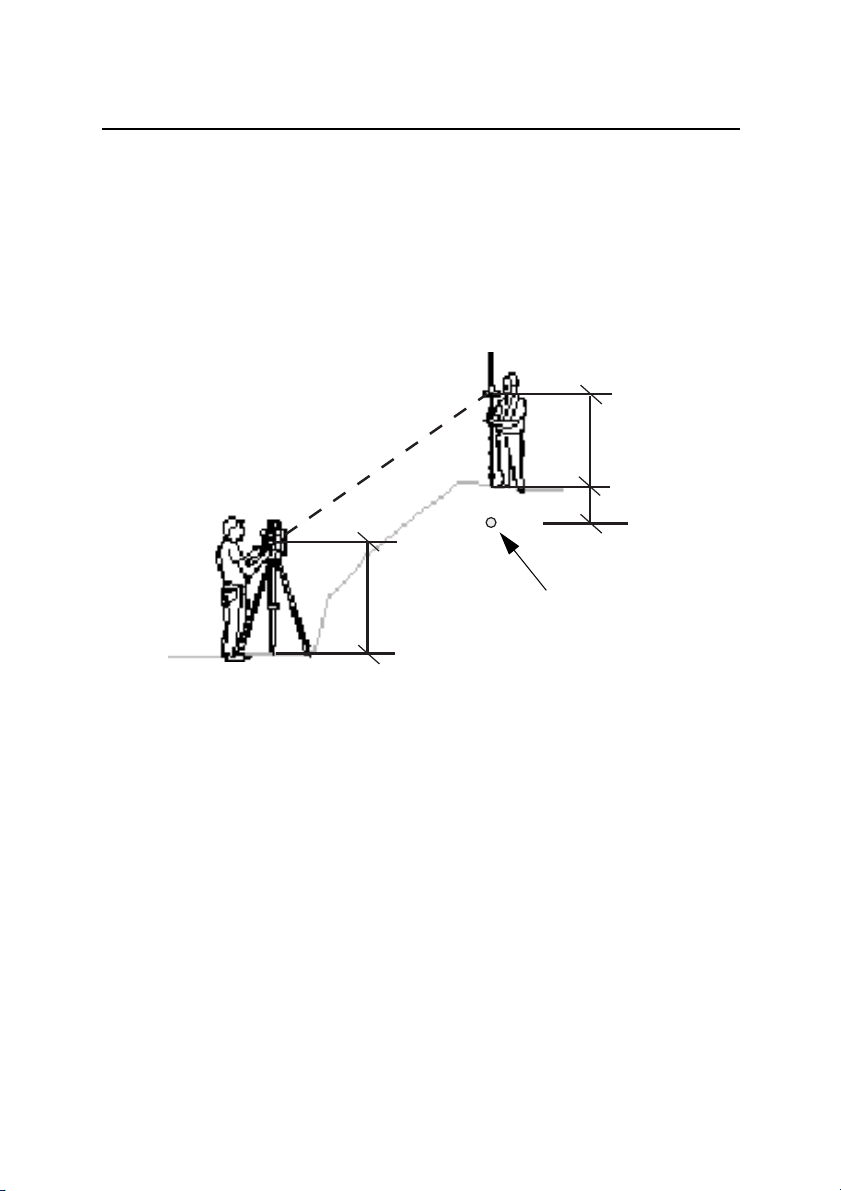
Overview
Tracklight is a visible guide light which enables the rodman
to set himself on the correct bearing. It consists of a
flashing three coloured light, each colour lying within its
own lateral projection sector. If the rodman is to the left of
the measuring beam, he will observe a green flashing light;
if to the right, a red flashing light; if on-line with the
measuring beam of the instrument, a white flashing light.
The frequency of the flash will increase by 100% as soon as
the light beam strikes the reflector, which will confirm for
the staff – man that he/she is holding the rod in the correct
position. Once the rodman is on-line, the distance will
immediately appear on the display . T racklight also provides
the operator with an excellent facility for clearing sight
lines and for working during the hours of darkness.
From the figure on previous page, it can be seen that the
instrument measuring beam width at 100 m is 15 cm. The
width of the tracklight beam at the same distance is 10 m.
Overview
The tracklight unit slides onto the underside of the
measuring unit (see fig figure 6.2) and it is activated from
the keyboard.
Trimble 5600-series 6-3
Page 60

6 Tracklight
T
racklight
Figure 6.2 The Tracklight unit slides onto the underside of the
Changing the bulb
measuring unit.
In order to change the tracklight bulb, open the cover under
which the bulb is situated.
6-4 Trimble 5600-series
Page 61

Overview
Remove very carefully the bulb housing and replace the
spent bulb with a new one. Replace the bulb housing and
connect the cover with the screwdriver (figure 6.3).
Figure 6.3 The sketch shows how the Tracklight bulb
(6.3V/0.2A) should be removed from the connection
socket.
Trimble 5600-series 6-5
Page 62

6 Tracklight
6-6 Trimble 5600-series
Page 63

7Tracker
CHAPTER
7
Figure 7.1 The Trimble 5600 Series Tracking function.
Page 64

7 Tracker
Overview
Trimble 5600 Series can be equipped with a Tracker unit
which is needed when using the system for robotic
surveying or when performing conventional surveying with
Autolock.
The tracker has control over the instrument’s servos and
aims the instrument correctly towards the target, which in
these cases must be an RMT (Remote Target). An
automatic search function is optional.
7-2 Trimble 5600-series
Page 65

8Beam adjustment
Laser beam DR Standard.....................................................8-2
Overview......................................................................... 8-2
Alignment........................................................................ 8-2
Adjustment...................................................................... 8-4
Laser Pointer DR 200+ & DR 300+...................................... 8-6
Overview......................................................................... 8-6
Alignment........................................................................ 8-6
Adjustment...................................................................... 8-7
CHAPTER
8
Page 66

8 Beam adjustment
Laser beam DR Standard
Overview
The red laser beam used for measuring without reflector is
coaxial with the line of sight of the telescope. If the
instrument is well adjusted, the red measuring beam will
coincide with the visual line of sight. External influences
such as shock or large temperature fluctuations can displace
the red measuring beam relative to the line of sight. The
measuring beam is also used as a laser pointer.
Alignment
Check the system at regular intervals in order to avoid
faulty measurements with the provided adjustment target.
Set up the adjustment target between 25 and 50 metres
away facing the instrument. Switch on the red laser beam
by activating the laser pointer function. Direct the
instrument to the centre of the target plate and then inspect
the position of the red laser spot with respect to the hair
cross of the instrument. If the red laser spot lies outside the
8-2 Trimble 5600-series
Page 67

Laser beam DR Standard
limits of the cross, the direction of the beam needs to be
adjusted until it coincides with the hair cross.
Attention! Viewing the laser spot on the adjustment target
through the telescope is safe. Do not try to make the
adjustment using a prism.
Tip! The direction of the beam should be inspected before
precise measurement of distances is attempted, because an
excessive deviation of the laser beam from the line of sight
can result in imprecise distance measurements.
Trimble 5600-series 8-3
Page 68

8 Beam adjustment
t
Adjustment
Pull the two plugs out of the adjustment ports on the top of
the telescope housing.
Vertical beam
adjustment port
To correct the vertical position of the laser spot, insert the
allen key into the vertical adjustment port and turn it.
Horizontal beam
adjustment por
8-4 Trimble 5600-series
Page 69

Laser beam DR Standard
To correct position of the laser spot horizontally, insert the
allen key into the horizontal adjustment port and turn it.
Finally check the coincidence of laser spot and hair cross.
Throughout the adjustment procedure, keep the telescope
pointing to the adjustment target. The adjusting screws are
of a high tension as they are self blocking. The screws will
tighten automatically after the adjustment.
Attention! Make sure that the plugs are correctly in place
in the adjustment ports to keep out humidity and dust.
Trimble 5600-series 8-5
Page 70

8 Beam adjustment
Laser Pointer DR 200+ & DR 300+
Overview
Trimble 5600 DR 200+ & DR 300+-series can be equipped
with an optional Laser Pointer. The Trimble 5600 DR 200+
& DR 300+ Series instrument with Laser Pointer has been
tested and complies with the regulations for a class 2 Laser
product, see laser safety information on the fist pages of
this manual
Alignment
The Laser Pointers alignment can be checked and if needed
adjusted.Tools for alignment are supplied with the
instrument, see figure below .
Figure 8.1 Laser pointer adjustment tools
8-6 Trimble 5600-series
1pcs. Allen key
1pcs. Laser
adjustment target
Page 71

Laser Pointer DR 200+ & DR 300+
nt
Adjustment
Mount the Laser adjustment target vertically aligned at a
distance of about 10m or more from your instrument, at the
same height as your instrument.
Power up the instrument, set the instrument in Direct
Reflex mode and switch on the laser pointer.
Align the telescope haircross with the lower reference cross
on the target.
Adjust the Laser Pointer beam with the horizontal and
vertical adjustment screws until the laser point is centred on
the upper reference cross on the target. See figure below.
Horizontal
adjustment
screw
Vertical
adjustme
screw
Figure 8.2 Laser Pointer adjustment screws
Trimble 5600-series 8-7
Page 72

8 Beam adjustment
8-8 Trimble 5600-series
Page 73

9Radio
Overview..............................................................................9-3
CHAPTER
9
Radio controls................................................................. 9-3
Select radio channel .......................................................9-3
Station address...............................................................9-3
Radio license ..................................................................9-4
Range .............................................................................9-4
Page 74

9 Radio
Figure 9.1 The Trimble 5600 Series with radio side cover.
9-2 Trimble 5600-series
Page 75

Overview
To be able to communicate between the instrument and the
RPU the instrument must be equipped with a radio side
cover and the keyboard unit must be connected to an
external radio. The radio side cover consists of a built in
radio and an antenna.
Radio controls
Select radio channel
The radio channel is selected from the Control Unit. Up to
12 channels can be used depending on how many are
supplied or permitted by authorities in each country. Select
a channel when the CU is attached to the instrument. Then
when the CU is detached and connected to the external
radio, this radio will automatically get the same channel as
the instrument. The range of different channels makes it
possible to work with more then one Trimble 5600 at a
working site. It is though important that each system has its
own radio channel so that not any disturbances will occur.
Overview
Station address
If disturbances occur on the radio channel from other
systems in the same area, try to change channel. If that does
not help the instrument and the RPU can be given an unique
address. Choose menu 1.5, Radio with the keyboard unit
attached to the instrument. Here you are prompted to enter a
station address and a remote address between 0 and 99.
Trimble 5600-series 9-3
Page 76

9 Radio
Radio license
Range
Note that the radio frequencies used are not harmonized
within EC and only permitted in one particular country or
area. Make sure that your radio is intended for the country,
where it is to be used. The information of destination
country can be found on the External radio or on its
package.
Before using the system at your working site it is important
to know that in some countries it is necessary to have a user
license. Make sure that your local agent has informed you
about the regulations in your country.
The actual range in which the radio can work is depending
on the conditions. Range can be decreased if other radios
are in operation in your area or when you are working in an
area with many reflecting objects.
9-4 Trimble 5600-series
Page 77

10Power Supply
Batteries............................................................................. 10-2
Internal Battery unit (Central unit).................................10-2
External Battery/Radio Battery...................................... 10-2
Single Adapter ..............................................................10-3
Multi Adapter.................................................................10-3
Battery Cables ..............................................................10-4
Battery Charging................................................................10-5
Power Unit (571 906 146)............................................. 10-6
About charging NiMH (and NiCd) batteries................... 10-6
Bat Low......................................................................... 10-6
CHAPTER
10
Page 78

10 Power Supply
Batteries
Internal Battery unit (Central unit)
The internal NiMH 12 V, 1.6 Ah battery unit (Part Nr. 571
242 460) slides into the underside of the measuring unit.
This is the standard battery for the measuring unit.
Figure 10.1 Battery unit 12V for central unit.
External Battery/Radio Battery
The external NiMH 12V, 3.5 Ah battery (Part No. 571 204
270), which is also common to other Spectra Precision
products, is connected to the instrument via the Single
Adapter (Part No. 571 204 256) or Multi Adapter (Part No.
571 204 273) described below and a standard Hirose cable.
The battery also fits directly on the External Radio.
10-2 Trimble 5600-series
Page 79

Figure 10.2 External Battery/ Radio Battery, 12V, 3.5 Ah
Single Adapter
The Single Adapter (Part No. 571 204 256) is used when
you want to connect the External NiMH Battery (Part No.
571 204 270) to the Trimble 5600 Series instrument via a
standard Hirose cable. The adapter slides onto the upper
side of the External Battery. The adapter has two Hirose
connectors and a bracket for attaching it to a tripod.
Batteries
Multi Adapter
The Multi Adapter (Part No. 571 204 273) is used to
connect up to three External NiMH Battery units (Part No.
571 204 270) to the Trimble 5600 Series instrument via a
standard Hirose cable. The adapter slides onto the upper
sides of the External Batteries. The adapter has 2+2 Hirose
connectors and a bracket for attaching it to a tripod. Three
External Batteries will result in a total capacity of 10.5 Ah!
Trimble 5600-series 10-3
Page 80

10 Power Supply
Battery Cables
The multi functional cable is required if an external battery
is used or when connecting the different Spectra Precision
devices with each other. The different types of cables are
listed below:
Multi functional Cable 1m, 571 202 188, for connecting
the Trimble 5600 Series instrument or control unit to an
external battery via the Single or Multi Adapter or to
another control unit or instrument. Length: 1.0m.
Multi functional Cable 2.5m, 571 202 216, same as the
above cable. Length: 2.5m.
Multi functional Cable 0,4m, 571 208 043, same as the
above cable. Length: 0.4m.
Multi functional spiral cable 0.75-1.75m, 571 208 068,
same as the above cable. Length: 0.75-1.75m.
Data Communication Adapter, 571 202 204, for
connecting the Trimble 5600 Series instrument or control
unit to a computer and Power Supply or an external battery
using the Single or Multi Adapter.
10-4 Trimble 5600-series
Page 81

Battery Charging
Trimble AB produces special NiMh and NiCd battery
chargers which should always be used when charging
Trimble batteries. The system contains the following
different types of units:
Single Charger (571 906 330)
A 230 or 115 VAC single battery charger. The charger has a
single Hirose output that can handle one NiMH External
Battery (571 204 270). Use together with Power Cable 571
905 925 (100-115V), 571 905 924(220V) or 571 908 040
(230V, UK plug) and Charger Cable 571 208 020 (for other
batteries).
Super Charger (571 906 145)
A microprocessor controlled charger for sequential
charging of up to four Trimble NiMH or NiCd batteries. It
is run with 10-30 VDC and is fitted with a connector to suit
both 19mm and 12mm cigarette lighter sockets. It shall
only be used together with Trimble Power Unit (571 906
146). The ambient temperature while charging should be
between +-0 C and +40 C. Use together with Charger Cable
571 208 020 (for other batteries).
Battery Charging
Warning – The Super Charger is for use together with Power
Unit 571 906 146 only! Other power units or charging
converters must never be used together with Super Charger.
Trimble 5600-series 10-5
Page 82

10 Power Supply
Power Unit (571 906 146)
A 90-260 VAC charging converter for use together with
Super Charger (571 906 145). The Power Unit is equipped
with a cigarette lighter socket and two Hirose connectors
for Trimble 5600 Series system cabling. Use together with
Power Cable 571 905 924 (230V), 571 905 925 (100-115V)
or 571 908 040 (230V, UK plug).
About charging NiMH (and NiCd) batteries
The temperature while charging should be above +5 C but
should not exceed room temperature. The condition of the
battery will be better preserved if it is used until the Trimble
5600 indicates “Bat Low” and the automatic cut-out
function is activated. Discharge of stored batteries can vary
considerably, depending on the quality of the individual
cells, especially at higher temperatures. It is therefore
recommended to store them in room temperature or lower
and recharge batteries if they have been stored for a longer
period than two one month.
Note – Please refer to the battery chargers instructions.
Bat Low
When battery capacity drops too low , “Bat Low” appears in
the display window , and the instrument shuts off
automatically. This gives you an opportunity to change the
battery without losing instrument parameters and functions
such as instrument height, signal height, coordinates,
bearing, dual axis compensation, etc. Note that the battery
change must be made within 2 hours; otherwise the above
parameters and functions will be reset.
10-6 Trimble 5600-series
Page 83

Battery Charging
Note – This safety backup of the instrument’s parameters
and functions will work only when “Bat Low” appears on
the display: It will not function if the battery is removed
during operation.
Trimble 5600-series 10-7
Page 84

10 Power Supply
10-8 Trimble 5600-series
Page 85

11Care & Maintenance
Overview............................................................................ 11-2
Cleaning............................................................................. 11-3
Condensation..................................................................... 11-3
Packing for Transport......................................................... 11-3
Warranty............................................................................. 11-3
Service............................................................................... 11-4
CHAPTER
11
Page 86

11 Care & Maintenance
Overview
Trimble 5600 Series is designed and tested to withstand
field conditions, but like all other precision instruments, it
requires care and maintenance.
• Avoid rough jolts and careless treatment.
• Keep lenses and reflectors clean. Always use lens paper
or other material intended for cleaning optics.
• Keep the instrument protected in an upright position,
preferably in its transport case.
• Don´t carry the instrument while mounted on the tripod
in order to avoid damage to the tribach screws.
• Servo instruments only: Do not rotate the instrument by
the handle. This may have an affect on the HA ref. How
much it effects the value depends on the quality of the
tribach and the tripod. Use instead the servo controls to
rotate the instrument.
• Don´t carry the instrument by the telescope barrel. Use
the handle.
• When you need extremely good measurement precision,
make sure the instrument has adapted to the surrounding
temperature. Great variations of instrument temperature
could affect the precision.
Warning – Trimble 5600 Series is designed to withstand
normal electromagnetic disturbance from the environment.
However, the instrument contains circuits sensitive to static
electricity and the instrument cover must not be removed by
unauthorized personnel. If the instrument cover has been
opened by an unauthorized person, the function of the
instrument is not guaranteed and the instrument warranty
becomes invalid.
11-2 Trimble 5600-series
Page 87

Cleaning
Caution must be exercised when the instrument is cleaned,
especially when sand and dust are to be removed from
lenses and reflectors. Never use coarse or dirty cloth or hard
paper. Anti-static lens paper, cotton wad or lens brush are
recommended. Never use strong detergents such as benzine
or thinner on instrument or case.
Condensation
After survey in moist weather the instrument should be
taken indoors, the transport case opened and the instrument
removed. It should then be left to dry naturally. It is
recommended that condensation which forms on lenses
should be allowed to evaporate naturally .
Packing for Tr ansport
The instrument should always be transported in its transport
case, which should be locked.
Overview
For shipment to a service shop, the names of the sender and
receiver should always be specified clearly on the transport
case.
When sending this instrument for repair, or for other service
work, a note describing fault, symptoms or requested
service should always be enclosed in the transport case.
Warranty
Trimble AB guarantees that the instrument has been
inspected and tested before delivery. The length of the
warranty is stated in the Warranty Conditions.
Trimble 5600-series 11-3
Page 88

11 Care & Maintenance
All enquiries regarding the warranty should be directed to
the local Trimble representative.
Service
We recommend that you, once a year, leave the instrument
to an authorized Trimble service workshop for service. This
is to guarantee that the specified accuracies are maintained.
Note that there are no user servicable parts inside the
instrument.
11-4 Trimble 5600-series
Page 89

12Card Memory
Overview............................................................................12-2
Installation.......................................................................... 12-2
How to connect to a Trimble 5600 Series instrument ........12-2
How to insert the memory card..........................................12-5
Memory Card ..................................................................... 12-8
Handling hints .................................................................... 12-9
CHAPTER
12
Page 90

12 Card Memory
Overview
Note – The Card Memory only operates together with the
Geodimeter CU Control Unit.
The optional Card Memory (P71 222 000) opens the
possibility of storing measurement data on portable
PCMCIA, ATA Sundisk memory cards. These can then be
transferred between the instrument and a PC and vice versa
without having to bring the instrument with you.
Installation
How to connect to a Trimble 5600 Series
instrument
You can attach the Card Memory unit in two ways:
1. If you have to have Panel Attachment at the front of the
instrument, that is the side opposite to the operator, you
12-2 Trimble 5600-series
Page 91

Installation
can attach the Card Memory unit to the instrument in the
same way as the ordinary keyboard unit.
Figure 12.1 How to attach the card memory on an instrument
2. You can also hang the Card Memory while in this case
on the tripod and attach it to the foot connector on the
instrument with the system cable, see page 10-4.
Figure 12.2 How to connect the card memory using the system
cable.
Trimble 5600-series 12-3
Page 92

12 Card Memory
Figure 12.3 Attach the card memory to a battery with 2
connectors.
12-4 Trimble 5600-series
Page 93

Installation
Figure 12.4 Attach the card memory to a battery with 1
connector with the help of the T-connector.
How to insert the memory card
To insert the memory card into the Card Memory please do
the following:
1. Open the Card Memory door.
2. Turn the memory card so that you can read the
Geodimeter logotype from left to right.
3. Insert the card into the card slot until you hear a click.
4. Shut the Card Memory door until you hear a click.
Trimble 5600-series 12-5
Page 94

12 Card Memory
Figure 12.5 How to insert the memory card into the card
12-6 Trimble 5600-series
memory device.
Page 95

Installation
To replace the memory card do the following:
1. Open the Card memory door.
2. Press the small knob in to the card slot until the memory
card is ejected.
3. You can now take the card and shut the Card Memory
door.
Trimble 5600-series 12-7
Page 96

12 Card Memory
Memory Card
The memory card for the Card Memory must be a type
called PCMCIA. It can be read from any card reader that
can handle PCMCIA cards of ATA, Sandisc type.
Figure 12.6 Trimble Memory Card
Capacity
The card can store up to 32 MB of measurement data.
Memory structure
The memory card can be use to store two types of data:
survey measurements (Job files) and known coordinates
(Area files). These Job- and Area-files consist of separate
expansive submemories which means that they can be
updated individually at any time without affecting other
Job- and Area-files. The total number of files is limited to
the total capacity of the memory. The more raw data stored
in Job files, the less known coordinate and elevation data
that can be stored in Area files and vice versa. The files
name can be max. 8 characters and with 3 characters for the
12-8 Trimble 5600-series
Page 97

extension, e.g. TESTFILE.JOB. When you load files from a
computer to a memory card, you must load all the files
under the root catalogue if you wish to use the files in your
instrument.
Handling hints
• The Card Memory device is always the last device in the
serial chain. When having it attach on the panel
attachment you cannot communicate via the foot
connector.
• If you intent to have the Card Memory device attached
prior to starting the instrument, otherwise you cannot
communicate with it.
• If you have formatted a memory card yourself, you can
expect the access time to be a little longer than usual, the
first time you try to access the card.
• When using the editor and accessing large files from the
memory card, you can expect longer access times than
when handling files from the internal memory.
Memory Card
• It is recommended that you keep the Card memory door
closed at all times except when inserting the memory
card and that you take the device indoors after survey in
moist weather. It should then be left to dry naturally.
• If you have two keyboard panels attached to the
instrument at the same time, you cannot access the Card
memory.
Note – T rimble AB cannot be held r esponsible for any type
of memory loss using the card memory.
Trimble 5600-series 12-9
Page 98

12 Card Memory
12-10 Trimble 5600-series
Page 99

13RMT Remote Targets
In General..................................................................... 13-2
RMT 602....................................................................... 13-3
RMT 606....................................................................... 13-4
RMT 600 TS.................................................................. 13-5
RMT Super Multi Channel............................................. 13-7
RMT SLR...................................................................... 13-8
CHAPTER
13
Page 100

13 RMT Remote Targets
In General
Trimble 5600 series (servo) instruments equipped with an
optional Tracker unit can perform surveying tasks using the
Autolock function. If the instrument is upgraded with a
radio, you will also be able to perform Robotic surveying,
i.e one-person surveying. To be able to use the above
functions you must also use some type of Remote
Measuring Target (RMT). A Trimble Remote Measuring
T arget consists of a prism reflector and one or several active
tracker diodes. The great advantage of using active tracker
diode(s) is that you eliminate the risk of the instrument
locking on to other reflecting objects than the RMT. Today
there are five different models of RMT to choose between
for Trimble 5600 series. All RMT models complies with the
regulations for a Class 1 LED device.
Note – The typical range of the different RMT models is
depending on the weather conditions.
13-2 Geodimeter CU General
 Loading...