

Page 1

October, 1995
UNAVCO
Trimble 4000SSE Operator’s
Manual
This manual contains information prepared by the University Navstar Consortium
(UNAVCO) to assist Global Positioning System (GPS) operators in the successful
acquisition of research data. UNAVCO is sponsored by the National Science Foundation
to make GPS resources available for geoscience research. Please let us know how this
manual might be improved by contacting:
Katie Chick ..................................................................... (303) 497-8002
info@unavco.ucar.edu
FAX: (303) 497-8028
UNAVCO
University Corporation for Atmospheric Research
P.O. Box 3000
Boulder, Colorado 80307-3000
USA
Page 2

October, 1995
1 Field Training Outline
1.1 Overview
............................................................................................................... 1
1.1.1 Introduction to training class:
1.1.2 Equipment
1.1.3 Tripod and Tribrach
1.1.4 Antenna
1.1.5 Measure Height of Antenna
1.1.6 Power Setup
1.1.7 Power-up Receiver
1.1.8 Documentation
1.1.9 Downloading / End of Survey
1.1.10 Run your own survey
1.1.11 Troubleshooting
1.2 Suggestions
2 Tripod Set Up Procedure
2.1 For Tribrach with Non-rotating Optical Plummets
2.2 For Tribrach with Rotating Optical Plummet
...............................................................................1
.............................................................. 1
............................................................................................. 1
.............................................................................. 1
.................................................................................................. 1
.................................................................. 2
.......................................................................................... 2
................................................................................ 2
...................................................................................... 2
.............................................................. 3
........................................................................... 3
.................................................................................... 3
......................................................................................................... 4
..........................................................................5
........................................... 5
.................................................... 5
3 Trimble 4000 SSE Equipment Configuration for GPS Surveys
3.1 Power Requirements
3.2 Preparing for a GPS Survey
3.2.1 Antenna set-up
3.2.2 Power Configurations for the Trimble 4000SSE
........................................................................................... 7
................................................................................ 7
..................................................................................... 7
................................ 7
.............7
4 The Trimble 4000SSE Control Parameters (ver 6.12)
4.1 The Receiver’s Control Parameters
4.1.1 Logged Data Files
4.1.2 RTCM-104 Controls
4.1.3 Power-up Mode
4.1.4 SV Enable/Disable
4.1.5 Adjust Local Time
4.1.6 Baud Rate /Format
4.1.7 Remote Protocol
4.1.8 Reference Position
4.1.9 Masks/Sync Time
4.1.10 Positioning Mode
4.1.11 Power Control
4.1.12 L1/L2 Operations
4.1.13 NMEA-183 Outputs
4.1.14 Cycle Printouts
............................................................................... 12
............................................................................. 13
................................................................................... 13
............................................................................... 13
............................................................................... 14
.............................................................................. 14
................................................................................. 14
............................................................................. 14
................................................................................ 14
................................................................................ 14
..................................................................................... 15
................................................................................. 15
............................................................................. 15
.................................................................................... 15
4.1.15 PPS Output and Time Tag
4.1.16 Event Markers
..................................................................................... 15
4.1.17 Default Control Parameters
5 4000SSE Short Programming Sheet
5-1 Using the Modify Key for the Trimble 4000SSE
5-1.1 View Angle
5-1.2 Backlight
5-1.3 Power
5-1.4 Units of Measure
........................................................................................... 18
.............................................................................................. 18
................................................................................................... 18
................................................................................. 18
................................................................. 12
.................................................................. 15
............................................................... 15
......................................................16
.............................................. 18
...........................12
Page 3

October, 1995
5-1.5 Beeper Volume
5-1.6 Altitude Reference
5-1.7 Kinematic Alarms
.................................................................................... 19
.............................................................................. 19
................................................................................ 19
6 Downloading Trimble 4000 SSE Data with UNAVCO Command Assistant
6-1 Computer and Receiver Configuration
6-2 Turning on the Computer
.................................................................................. 20
6-3 Starting Trimble 4000 Downloading Software
6-4 Trimble 4000 Software Menu
6-5 Data File Display
................................................................................................ 22
............................................................................ 21
6-6 Selecting a Data File Destination
6-7 Renaming files
................................................................................................... 23
6-8 Selecting a Data File to Download
6-9 The Downloading Process
................................................................................ 23
6-10 Transferring Data to Floppy Disk.
6-11 Reading the Message (.MES) File
6-12 Checking Data Files on Floppy Disk
6-13 In Case of Power Failure
................................................................................... 25
6-14 Deleting Files using the 4000 Program
7 Disk Label Format
...................................................................................26
............................................................ 20
................................................ 21
..................................................................... 22
................................................................... 23
.................................................................... 23
..................................................................... 24
................................................................ 24
............................................................ 25
20
Page 4

July, 1995
1 Field Training Outline
This outline is a supplement to the instructions received from the UNAVCO engineer on GPS data
collection procedures. Verbal, visual, and, most importantly, hands-on instruction are necessary for an
operator to learn proper field techniques. These skills need to be attained during the training period - not
out in the field. Upon completion, operators must demonstrate the ability to responsibly operate and care
for field equipment.
1.1 Overview
1.1.1 Introduction to training class
a. Review schedule of training class.
b. Introduction of Principal Investigators (PI’s), instructors, and participants.
c. PI explains scientific objectives of the project and items of interest.
d. Project Engineer explains his/her role and responsibilities.
e. Receive notebooks, log sheets and handouts.
:
1.1.2 Equipment
a. Have a system already configured.
b. Assign receiver/system to the primary operator and explain the responsibilities of the operator:
Review the following.
c. Equipment checklist.
d. Unpacking and packing equipment.
e. Dropped or broken equipment. Report any problems to the engineer without hesitation.
f. Transporting equipment.
g. Care of computers and diskettes.
h. Transporting data.
i. Explanation of all equipment on the manifests.
1.1.3 Tripod and Tribrach
a. Tripod Set Up Procedure Chapter 2.
♦ Operators learn to set up a tripod and tribrach.
♦ Operators are given potential problems. Example: set up on a hill or on uneven
terrain.
1.1.4 Antenna
a. Explain the parts of the antenna and how it works.
♦ Location of the patch and electric phase center.
♦ Magnetic declination and importance of setting true north.
♦ Ground plane and multipath.
♦ Waterproofness and the role of the desiccant.
♦ Antenna cables.
♦ coiling the cable.
♦ dirt in the plugs.
1
Page 5

♦ don’t step on or pull on cables.
♦ first connect cable to the antenna first then to the receiver.
♦ stay away from the antenna during observations.
1.1.5 Measure Height of Antenna
a. How to read height stick.
b. Check independently with tape measure in inches.
c. Measure height and document it on log sheet.
♦ all 3 readings should be within 1 mm. This confirms the antenna is level.
♦ if greater than 1mm measure all notches and note problem on log sheet.
1.1.6 Power Setup
a. Explain power requirements of the receiver and length of time it takes a battery to lose all
power.
♦ Hand out ESG battery recommendations report.
♦ Car batteries.
♦ Explain jumping batteries in parallel and series.
♦ Demonstrate configuration with solar panels.
♦ Explain short circuiting, checking fuses and checking voltage.
♦ Charging batteries.
♦ OSM appears on screen.
♦ Explain the use of OSM or power download cable as alternate power supply.
♦ Power problems.
b. Connect battery to receiver.
July, 1995
1.1.7 Power-up Receiver
a. Hand out the Trimble Short Programming Sheets from the Investigators Manual.
b. Explain care of receiver.
♦ keep out of rain and sun.
♦ run survey in a tent, kinetics box or B box.
♦ fill out logbook after every observation session.
♦ Explain 6 ports in the rear of the receiver.
♦ Power up the receiver and watch self tests as they appear.
♦ Run through Trimble Short Programming Sheets.
1.1.8 Documentation
a. Explain all the boxes on the log sheets and have the operators fill it out legibly and correctly
as they conduct the survey.
b. Emphasize the use of all handouts. When in doubt refer to the handouts.
c. Field log sheets, diskette labels and receiver logbooks.
d. Updating station descriptions.
e. Collect all log sheets at the end of the day and correct them and return to the operators.
f. Emphasize the importance of filling out the logbooks for the receivers.
2
Page 6

1.1.9 Downloading / End of Survey
a. Stop the survey or watch the programmed stop and refer to Downloading Trimble 4000 Data
chapter 6.
b. Demonstrate the configuration of the download equipment.
♦ Demonstrate the setup of the OSM as an alternative to the download cable.
♦ Re-iterate care of computers. Avoid heat, dust and magnets.
c. Documentation on diskettes and log sheets.
d. Re-check antenna height and if centered exactly over the mark
e. Packing up and preparation for next day
♦ Demonstrate exactly how equipment should be packed in the box.
♦ Demonstrate tent setup and packup.
f. Charging batteries.
g. Check manifests.
h. Transportation to the next site.
i. Communication with engineer if necessary.
♦ Report any problems or tracking difficulties to the engineer.
July, 1995
1.1.10Run your own survey
a. Make all primary operators run their own survey from start to finish. Supervise carefully.
♦ Check antenna height and plummet.
♦ Check general system configuration.
♦ Check and correct parameters set during programming of survey.
♦ Documentation and download.
1.1.11Troubleshooting
a. Things to check at the beginning of the survey.
♦ Start and end times of the survey.
♦ Parameters programmed into the receiver.
♦ SNR values and continuous and total L1 and L2 observations.
b. Things to check during the survey.
♦ SNR values and continuous and total L1 and L2 observations.
♦ Position and velocity of position.
♦ Watch for animals or people near the equipment.
♦ Discuss danger of electrical storms.
♦ What to do in case of low battery power.
♦ What to do in case of power failure.
♦ What to do in case the antenna is off level during the survey.
c. Things to check at the end of the survey.
♦ What to do in case the antenna is off level at the end of the survey.
♦ What to do in case of power failure.
3
Page 7

1.2 Suggestions
a. Remember to allow 1 & 1/2 --> 2 hours to set up all equipment and program the receiver for
the first observation session.
b. Take care not to confuse UTC time and local time when programming the survey.
c. Use the correct parameters as defined by the PI when programming the survey.
July, 1995
4
Page 8

2 Tripod Set Up Procedure
2.1 For Tribrach with Non-rotating Optical Plummets
a. Extend tripod legs so the top of the tripod head comes up to your chin. Lock legs at this height
with the leg screws. If the ground is not level the legs will have to be extended at different
lengths.
b. Attach tribrach to tripod head using the large center screw on the tripod head. Make sure that
the leveling foot screws on the tribrach are centered half way between their range of movement.
c. Open tripod legs over the mark and step (set) one leg into the ground at about a 45o slant angle
and about 3 feet from the station mark. Look through the optical plummet and position the cross
hairs over the point using the remaining two tripod legs. If viewing or crosshairs are out of focus
adjust the crosshairs ring first until the crosshairs appear clear and crisp. Adjust the focus ring
until the image is in focus. To check for parallax slowly move your head around while looking
through the optical plummet. You should see no movement between the crosshairs and the
focused background (this is known as being out of parallax), nor should the crosshairs move
apart.
d. Once the cross hairs are within 1 cm of the point and the head of the tripod is visually level,
step the remaining two legs into the ground. At this point sand bag or tie down the tripod legs.
e. Precisely position the tribrach crosshairs over the point using the leveling foot screws on the
tribrach.
f. Level the bull’s-eye bubble on the tribrach by using two tripod legs. (Do not level using the tri-
brach foot screws.) At this point you are leveling the tripod head.
g. When the bubble is within the circle of the bull’s eye use the tribrach leveling foot screws to
precisely center the bubble.
h. Once the bull’s-eye bubble is precisely level, look through the optical plummet to ensure that
the crosshairs are over the point or at least within a few cms. Center the crosshairs precisely
over the point by loosening the tripod head screw and gently slide the tribrach over the point.
When centered tighten the tripod head screw.
i. Check the level bubble. If the level is outl:
♦ just a little - repeat steps g & h.
♦ by a lot - (more than a couple of mms) - repeat steps e,f,g,h.
j. Check the set up and calibration of the tribrach by attaching the plumb bob to the tribrach head
screw so it hangs over the point. It should hang precisely over the point +/- the plumb bob string
width. NOTE: This will not necessarily be true in windy conditions. In windy conditions the
plumb bob will be blown away from the mark. If the site is located in an area with high winds
the calibration of the tribrach can be checked indoors by performing the set up procedure.
July, 1995
2.2 For Tribrach with Rotating Optical Plummet
a. Proceed with steps 2-1(a-i).
b. Turn the tribrach so that the plate bubble tube is parallel to two footscrews. Center the bubble
by adjusting these two footscrews in equal and opposite directions.
c. Turn the tribrach through 90 degrees. Center the bubble with the third footscrew.
d. Turn the tribrach through 90 degrees so that the bubble is parallel to the first 2 footscrews. Note
position of bubble. If the bubble is centered between the middle divisions, then the tribrach is
5
Page 9
level in this plane. If the bubble sits more than one division off center, then note how many
divisions off center it lies and by adjusting the two footscrews in equal and opposite directions
bring the bubble toward the center by half the amount it was off center before. Turn the tribrach
through 180 degrees again and check where the bubble rests. Repeat the process until the
bubble is within one division of the central division.
e. Now turn the tribrach through 90 degrees and check the level in this plane. Note the position
of the bubble. If the bubble is off center by more than one division, turn the third footscrew to
bring the bubble to a point halfway between the position noted and the centered position.
Rotate through 180 degrees and check again using the third footscrew for any fine adjustment.
f. Now rotate the tribrach through 360 degrees and check if the bubble remains within 1 division
of the center for any position.
g. Center the adapter precisely over the point by loosening the tripod head screw and gently slid-
ing the tribrach over the point. When centered tighten the tripod head screw.
h. Check the set up and calibration of the tribrach by rotating the adapter 180 degrees and check
the plummet. If the tribrach is off center by more then 1mm then loosen the tripod head screw
and gently slide the tribrach half the distance it was off. Rotate the adapter 180 degrees and
recheck the plumb. The offset should be the same. If not repeat this step again.
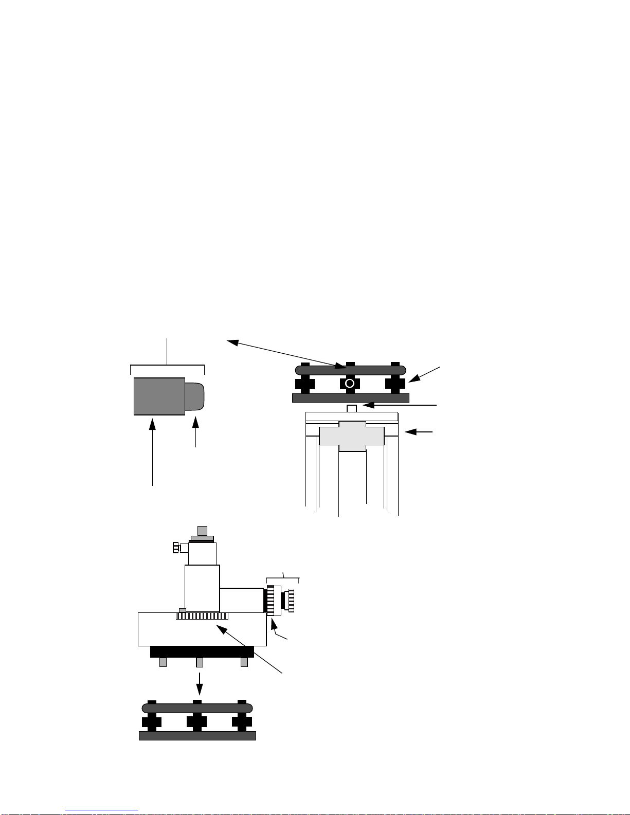
Figure 2-1 Diagrams of the two types of T ribrachs.
optical plummet
Non-Rotating Optical Plummet
July, 1995
focus ring
crosshair ring
tribrach
optical plummet
crosshair ring
focus ring
leveling
foot screws
tripod
head screws
tripod head
tripod
Rotating Optical Plummet
plate level tube
6
Page 10

3 Trimble 4000 SSE Equipment
Configuration for GPS Surveys
3.1 Power Requirements
The Trimble 4000SSE Receiver operates between 10.5 dc volts (Vdc) and 35 Vdc. The receiver will
automatically shut off if the voltage drops below 10.5 Vdc and it will not turn on if the power is less
than 11.5Vdc.
The receiver draws 9 watts of power. A fully charged 12V battery with a 10 amp hour(Ah) rating will
theoretically power the receiver for about 13 hours(10Ah / 9W X 12V). However, the amount of time
a battery can power the receiver can be misleading since the actual length decreases depending
on the operating temperature and the number of charging cycles the battery has gone through.
All UNA VCO’ s 12V gel cell batteries are tested to last at least 8 hrs at room temperature when fully
charged.
Many different power configurations for 4000SSE receiver exist. Two common configurations are
shown in figures 3-1 and 3-2. The power configuration shown in Figure 3-1 has two gel cell batteries
powering the receiver. This power configuration should be used for observation periods less then
15 hours. The configuration shown in Figure 3-2 is recommended if the receiver is to be used continuously for several days. In this configuration, two batteries and a set of solar panels are used.
Depending on available sunlight, the battery attached to the solar panels may sustain the receiver
for a week or more.
July, 1995
3.2 Preparing for a GPS Survey
3.2.1 Antenna set-up
a. Set the tripod over the mark. (refer to Chapter 2) Attach the antenna to the tribrach adapter.
Carefully slide the tribrach adapter into the tribrach, being careful not to disturb the tripod.
b. Carefully unroll the antenna cable.
c. Connect the antenna cable to the threaded connection on the antenna housing. Be careful not
to cross-thread the connection.
d. Connect the antenna cable to the antenna port on the receiver.
e. Orientate the antenna to true north and secure in place.
f. Secure the dangling antenna cable to the tripod so that it won’t blow in the wind.
g. Recheck the level and the centering of the antenna.
3.2.2 Power Configurations for the Trimble 4000SSE
a. Short-term Occupations (refer to figure 3-1)
1. Connect the two gel cell batteries to the two power ports.
♦
Note: The LIMO connection on the battery cable has a red dot. Line this red dot up
with the red mark on the power port.
b. Long-term Occupations (refer to figure 3-2)
1. Main Battery. Using the auxiliary battery cable, attach the car battery to power PWR 2/
3 port. Ensure the connections to the battery are correct. The positive (+) terminal is red or
white and the negative (-) is black.
7
Page 11

2. Backup Battery. Connect the 12V gel cell battery to the PWR I/O 1 port on the back of
the receiver.
3. Solar Panels.
♦ Attach the solar panel regulator to the solar panels. Place the regulator in a plastic
bag. Fold close the solar panels. Connect the alligator clips to appropriate terminals
on the main battery.
♦ Open the solar panels one panel at time. This avoids creating a power surge. Place
the panels in the sun in perpendicular to the sun’s rays. Ensure the panels are placed
in an area that has maximum sunlight over the course of the day.
Figure 3-1 Short Occupation Power Configuration.
12 V gel cell battery
July, 1995
Rear panel for
4000SSE Receiver
5 Amp
Fuses
Power Port
(PWR 2 & 3)
Power Port
(PWR I/O 1)
Antenna Port
Model #
Serial #
Trimble 4000 SSE/T L1/L2 Geodetic Antenna
8
Page 12

Figure 3-2 Long Occupation Power Configuration
Trimble 4000SSE Rx
(back panel)
ANENNA PORT
POWER I/O 1
POWER 2&3
Battery Power Cable
(fused)
July, 1995
Trimble 4000 SSE/T L1/L2
Geodetic Antenna
Backup Power Source
12V Battery (fused)
Solar Panel Regulator
(fused)in a plastic bag
Positive Negative
Main Power Source
12 V Car Battery
Solar Panels
9
Page 13

Figure 3-3 Trimble 4000SSE Front Display and Back Panel Ports
Trimble
July, 1995
ABC
DEF
1
GHI
2
3
ENTER
CLEAR
STATUS
TIME
JKL
STU
MNO
4
7
VWX
PQR
5
8
YZ--
6
9
+
ALPHA
0
SESSION
LOG DATA
ALPHANUMERIC KEY PAD PROGRAM KEYS
EXT REF
ANTENNA
AUX
MODEL #
SERIAL #
PWR-I/O 1
PWR 2 & 3
I/O 2
SAT INFO
CONTROL
POWER
MODIFY
SOFT KEYS
EXTERNAL REFERENCE TIMER
(NOT USED)
POWER & INPUT/OUTPUT
(5 PIN)
ANTENNA
POWER 2 & 3 (5 PIN)
AUXILLARY (7 PIN)
(NOT USED)
INPUT/OUTPUT (7 PIN)
(NOT USED)
10
Page 14

Figure 3-4 Configurations for Battery Charging
r
July, 1995
12V Car Battery
110 /120
Volts AC
Red Clip (positive) Black Clip (negative)
Car Battery Charger
Surge Suppressor
Ensure the Amperage is set correctly
Battery Charging Configuration using a variable Amp Output Car Battery Charge
110 /120 210 /240
Volts AC
12 V Gel Cell Battery
Black Wire (negative)
White Wire (positive)
Red Clip (positive)
Black Clip (negative)
Battery Charger
Ensure the Voltage
is set correctly
(120V or 240V)
Surge Suppressor
Battery Charging Configuration using a 12 Volt, 2 Amp Output Battery Charger.
11
Page 15

July,1995
4 The Trimble 4000SSE Control
Parameters (ver 6.12)
For Trimble Receivers with V6.12 Nav Software
This guide indicates the receiver’s default settings to be used for normal surveys. This guide does not
cover pre-programming the Trimble receiver. The instructions are not intended as a substitute for the
Trimble 4000SSE Operation Manual
programmed.
The Trimble 4000SSE GPS receiver operates between 10.5 & 35 VDC 9 watts nominal power. One 12V
(~12 Ah) sealed dry cell battery will provide about 8 hours of operating time when in good condition and
fully charged. The system will simultaneously track up to 9 satellites in both L1 and L2 and can store
almost 224 hours of survey data (8 SVs at a 30 seconds collection interval) on its 5-Mbyte RAM memory.
The following are ground rules for the use of UNAVCO equipment:
a. At all times, UNAVCO equipment must be operated from a covered area (such as inside a car,
tent, or building).
b. UNAVCO equipment must never be transported outside of their cases.
c. Never leave the equipment unattended. The operator is held responsible for data acquisition
and safekeeping of equipment in their care.
d. Never attempt to modify nor repair any piece of UNAVCO equipment. If you break something,
call the UNAVCO project engineer immediately.
. Consult the project engineer if your receiver is to be pre-
The following is a list of the receiver default settings. These defaults should not be changed unless
instructed by the project Engineer.
When the power key is pressed, the 4000SSE system will first go through a number of self tests.
4.1 The Receiver’s Control Parameters
The Trimble 4000 SSE Front Display and Back Panel (fig. 3-3) the front view of the Trimble 4000SSE
display panel. Control inputs are accessed via the CONTROL key. The control parameters, with the
exception of deleting old data files, do not need to be changed each time the receiver is turned on. The
control parameters are preset at UNAVCO and should not be changed unless instructed by the field
engineer.
The following is a list of the receiver’s control parameters and a brief description of what they are used for.
At any point in the CONTROL menu the CLEAR key can be pressed one or more times to exit.
NOTE: Not all receivers will have all the options listed below. Some may have more too.
4.1.1 Logged Data Files
This control parameter allows you to check the receiver’s memory for stored files. In this menu, files can be
deleted or recovered.
12
Page 16

July,1995
♦ Deleting Data Files
To delete files press the DELETE key. When the key is pressed the following screen will appear with the
data files from previous surveys.
1
Figure 4-1 Information displayed when DELETE key is pressed
FILE NAME
FILE: UN07-086-0 INDEX: 01
CREATED: 19:02 UTC
NUMBER OF THIS FILE IN RECEIVER
NEXT FILE
PREV FILE
WED 24-03(MAR)-93
145 KBYTES 2345 RECORDS
SIZE OF FILE
To delete the file shown press the DELETE IT key. To delete other files in the receiver’s memory press the
NEXT FILE key until the desired file is displayed. To clear the receiver ’s memory press DELETE IT until
“FILE DIRECTORY IS EMPTY” is displayed. Press the CONTROL key to return to the main menu.
Deleting the files leaves a full block of memory for observations. When a file is deleted it can still be
recovered only if no other data has been written to the memory.
♦ Recovering Data Files
DELETE IT
If you need to recover previously deleted files, follow the same procedure as above but select RECOVER
instead of DELETE. Then select the data file to recover by pressing the NEXT FILE key until the desired
file is displayed: Once the desired file to recover is displayed press the RECOVER IT key.
4.1.2 RTCM-104 Controls
The option for RTCM-104 INPUTS and PORT SELECT should be off. This option allows the receiver to
compare previously stored coordinates with computed values from GPS measurements. The receiver can
then send out corrections to remote receivers via a communications system. An example of the use of this
option would be for navigating. For example, a receiver could be placed at a known base station at the
entrance of a harbor and then send out GPS corrections to incoming ships.
4.1.3 Power-up Mode
This option should be set to DEFAULT OF CONTROLS. This option is used in conjunction with the RTCM
option and other navigation options. It sets the receiver to default to certain parameters when power is lost
and then restored.
4.1.4 SV Enable/Disable
Each SV can be tracked in one of four modes, IGNORE HEALTH (SURVEYING), DISABLED, ENABLED,
and IGNORE HEAL TH (POSITIONING) . A satellite can be either listed healthy or unhealthy. The health of
a particular satellite can be changed without warning by the U.S. Government for a variety of reasons. No
1. NOTE: Only files that have been downloaded should be deleted.
13
Page 17

July,1995
SVs should be DISABLED. For most GPS surveys IGNORE HEALTH (SURVEYING) will be used. To
check that all SVs are IGNORE HEALTH (SURVEYING) press the MORE MODES key. Under the
IGNORE HEALTH (SURVEYING) menu all the satellite numbers should be listed. If any option other than
IGNORE HEAL TH (SURVEYING) had SVs listed check with the project engineer to be sure this is correct.
The differences between the settings are:
♦ IGNORE HEALTH (SURVEYING): Receiver will attempt to log data fram a satellite
regardless of its health. The data can then be evaluated during post-processing.
♦ DISABLED: Receiver will not tract a specified satellite.
♦ ENABLED: Receiver will only track a satellite if it is healthy.
♦ IGNORE HEALTH (POSITION): Receiver will attempt to track satellite regardless of
health. This option is used in conjunction with navigation purposes. Only psuedo-range data
will be collecected.
4.1.5 Adjust Local Time
The TIME OFFSET (UTC-UTC) should be 0:00 and the TIME ZONE IDENTIFIER = UTC. For all surveys
the local time is UTC. This eliminates any time errors that could occur due to time zone differences within
the project area.
4.1.6 Baud Rate /Format
The settings for PORT 1 should be BAUD RATE: 9600 and FORMAT: 8 ODD 1. PORT 2 should be the
same. This option is used to control the communications between the receiver and any external device attached to it (e.g. a download computer).
4.1.7 Remote Protocol
This options is used in conjunction with external devices (i.e. a datalogger) and for making firmware updates. This option is not used for UNAVCO GPS surveys.
4.1.8 Reference Position
The default value is all zeros. The receiver uses an “anywhere fix” operation and does not need to know
where it is to start a survey.
4.1.9 Masks/Sync Time
This option allows you to change the elevation mask and sync time while a survey is in progress, however,
these values are entered into the receiver when the receiver is programmed for a specific survey.
4.1.10 Positioning Mode
The receiver can be set to determine it’s position using several different options.
♦ latitude, longitude, and height or latitude/ longitude (depends on # of satellites)
♦ latitude/ longitude (fixed height)
♦ height (fixed latitude/ longitude)
♦ latitude, longitude, and height always (depends on # of satellites)
The determined position can either have a weighted solution or not. The positioning mode is used mostly
for navigation purposes. For UNAVCO GPS surveying purposes all data is stored and then analyzed later.
The real time position is not used.
14
Page 18

July,1995
4.1.11Power Control
This option is set to off. This option allows for the receivers internal battery charger to be turned on or to
power external devices plugged into the ports. The option can only be used if a Trimble Office Support
Module (OSM) is powering the receiver.
4.1.12 L1/L2 Operations
All 9 channels are configured to collect both L1 P (P-code) and L2P (P-code) data. During times of AntiSpoofing (AS) the receiver will automatically switch to cross-correlation tracking mode (L1P and L2x).
4.1.13 NMEA-183 Outputs
All options should be set to off. NMEA-183 (National Maritime Electronic Association) is used for
navigation purposes. This option allows the receiver to output six different navigation parameters to aid
with other navigational sensors.
4.1.14 Cycle Printouts
This is a printer output option used for navigation purposes and is not needed for UNAVCO supported
surveys, therefor, ENABLE is OFF.
4.1.15 PPS Output and Time Tag
This option is a time strobe and its associated time tag. The 1PPS OUTPUT is [DISABLED], the SLOPE is
NEGATIVE and the ASCII TIME TAGS are set to [NONE].
4.1.16 Event Markers
This option is used to provide a precise GPS time tag for an externally generated pulse, i.e. a photogrammetric camera. This is option is always DISABLED.
4.1.17 Default Control Parameters
This option is used to set the receiver to a factory default condition. It should not be used unless instructed
by the field engineer.
15
Page 19

1.
December 1993
5 4000SSE Short Programming Sheet
Selection Explanation
Program the receiver at least 20 minutes before
scheduled start time. Turn the receiver on by
POWER
pressing the POWER key. Receiver will boot and self
test. Watch for any errors during self test.
2.
3.
4.
5.
Answer Question
3a.
3b.
NEW STATION: 0000
NAME:
NEW SESSION: 000-0
CLEAR
CONTROL
LOGGED DATA FILES
DELETE
DELETE IT
DELETE IT
SESSIONS
DELETE IT
ENTER
ENTER
AUTOMATIC
“###-#”
ENTER
Press the clear key to display status of receiver. Check
for proper operation: satellite tracking status, AC or DC
(battery status) power, external antenna symbol
(’lollipop’), and UTC time.
Have data files been downloaded, by you?
YES: Go to 3a
NO : Go to 3b
Delete all files that have been successfully downloaded
and copied onto backup disks. This will provide
additional data storage space for session.
Delete the files until you see “FILE DIRECTORY IS
EMPTY”.
Go to 3b.
Delete until you see “NEW STATION: 0000”.
Input 4 character station ID and push ENTER.
Input station name (up to 48 characters) and push
ENTER.
REFERENCE POSITION FOR: 0000 AUTOMATIC.
Input the DAY OF YEAR (3 digits) - SESSION
(1 digit) and push ENTER.
6.
.
7.
START TIME: "##:##" UTC
OBSERVATION TIME: “##:##” (hh:mm)
8.
9.
ELEVATION MASK: “15”
MIN SV’s: “03”
MEAS SYNC TIME: “015.0” SEC
ADD ANOTHER SESSION FOR
STATION: ?
USE RECEIVER DEFAULTS
ANY DAY AT SPECIFIED TIME
ACCEPT
ACCEPT
NO
USE RECEIVER DEFAULTS.
Schedule the new session:
Input hours:minutes.
Input hours:minutes of length of survey.
Enter numeric value (usually 100 see notebook)
Enter numeric value (usually 01)
Enter numeric value (see notebook)
Add another session for that station? NO
16
Page 20

ADD ANOTHER STA TION ?
10
.
Selection Explanation
NO
NO
Add another Station? NO
December 1993
11.
12.
13.
14.
15.
16.
17.
START PRE-PLANNED (SINGLE SURVEY)
Review
SELECT STATION:
NEXT, PREV,
ACCEPT
SELECT SESSION:
NEXT, PREV,
ANTENNA HEIGHT : “##.####” METERS"
MEASUREMENT TYPE: UNCORRECTED ANTENNA #:
ANTENNA # “##.####”
START SURVEY
ACCEPT
ENTER
ACCEPT
MORE
MORE
MORE
MORE
Select type of survey. DO NOT PRESS "QUICK START"
Review previous input parameters.
Select proper station using NEXT STATION or PREV
STATION. Press ACCEPT key when correct.
Select proper session using NEXT SESSION or PREV
SESSION. Press ACCEPT key when correct.
Input antenna slant height in meters and push ENTER.
Input “0” followed by the last 5 digits of the antenna serial
number and press ACCEPT.
PRESS START SURVEY KEY. Start survey
15 minutes before scheduled start time.
Immediately press the MORE key to
check if START AT, STOP AT, ELEVATION MASK,
logging INTERVAL, and MINIMUM NUM. SVs are
correct.
OR
SURVEY
END SURVEY
STOP THE CURRENT SURVEY? YES
LOG DATA
If they are NOT correct stop survey by pressing
SURVEY or LOG DATA key.
Then select END SURVEY and STOP THE CURRENT
SURVEY?
YES.
After the survey has stopped. Go to 3b.
If they ARE correct monitor status of receiver: logging
status, logging time, power, antenna symbol, UTC time
and number of measurements.
TO END PROGRAMMED SURVEY
Survey will end automatically. When the survey has
ended the screen will return to the status display. When
the survey has ended turn power off by pressing and
holding the POWER key before unplugging the power
source.
17
Page 21

July 19, 1995
5-1 Using the Modify Key for the Trimble 4000SSE
The MODIFY key allows the Trimble 400SSE user to change certain receiver parameters. The
parameters are:
♦ View Angle
♦ Backlight
♦ Power
♦ Units of Measure
♦ Beeper Volume
♦ Altitude Reference
♦ Kinematic Alarms
To change any of the above parameter start by pressing the MODIFY key.
Note: The modify key can be accessed anytime without affecting the survey in progress.
Press the key
To return to the main modify menu at any time:
Press the key
CONTROLMODIFY
CONTROLCLEAR
5-1.1 View Angle
The screen’s view angle can be adjusted up or down by pressing the VIEW ANGLE key. Adjust the display
view angle by pressing the up or down key.
5-1.2 Backlight
The display backlight’s brightness can be increased or decreased and the backlight time-out interval can
be set by pressing the BACKLIGHT key . you want to have the brightness decreased to the lowest level and
the time-out set to one minute.This will help maximize battery power performance.
5-1.3 Power
The battery power status can be checked and the receivers power input port can be changed by pressing
the POWER key. The receiver operates between 10.5 and 35 volts DC. The receiver will not start unless
the voltage is above 11.5v. When the receiver powers up the instrument will search the 2 power ports for
the lowest-voltage port. The receiver will attempt to use that battery fully and then switch automatically to
the next lowest port. You can select which power port to use by pressing the appropriate softkey. When
using solar panels you want to use the power port with the battery that the solar panels are attached to.
When a battery is fully charge from using the solar panels switch the panels to the second battery and
change the power port.
5-1.4 Units of Measure
Press the MORE key to access the receiver modify menu (2 of 3). The units of measure option allows you
to select the units in which the following are displayed:
18
Page 22

July 19, 1995
♦ latitude and longitude (degrees/minutes/seconds or degrees/minutes.minutes)
♦ antenna height (meters/centimeters/feet or inches)
♦ time (24 hour UTC, 12 or 24 hour local
♦ position =WGS84 LLH
Select the desired units by pressing the appropriate CHANGE softkey.
5-1.5 Beeper Volume
Use the beeper volume option to change the volume of the KEYPRESS BEEP or the CYCLE BEEP. To
maximize battery performance set the KEYPRESS BEEP down to the lowest level and the CYCLE BEEP
down to OFF.
5-1.6 Altitude Reference
The altitude reference option allows you to change the format of the displayed elevation between
ELLIPSOID (WGS-84) and M.S.L. (mean sea level).
5-1.7 Kinematic Alarms
Press the MORE softkey to access the receiver modify window (3 of 3). If conductions a kinematic survey
you can adjust the volume up or down for the POOR PDOP ALARM and RETURN TO MARK ALARM.
19
Page 23

DRAFT
6 Downloading Trimble 4000 SSE Data
with UNAVCO Command Assistant
6-1 Computer and Receiver Configuration
Configure the receiver and computer in the download configuration shown below. It is recommended that
the download process takes place while the computer and receiver are powered by a battery and not A/C
power. If either battery is too low to accomplish the download then A/C power should be used. If A/C power
is used, connect the computer’s A/C adapter provided and attach the battery charger to the battery
connected to the receiver.
REAR PANEL TRIMBLE 4000 SSE
Ver 1.0a
July, 1995
EXT REF
PWR-I/O 1
RS232 Download Cable
ANTENNA
PWR 2 & 3
AUX
I/O 2
12volt battery
To Comm Port 1
DOWNLOAD COMPUTER
Figure 6-1 Configuration for Downloading.
6-2 Turning on the Computer
Turn on the computer . The system will go into a menu program called
If you turn on your computer and the system does not boot into the menu program, then at the C:\> prompt
type: MENUASST and press <Enter>.
♦ If the
1. Some systems have a cable that functions both as a download cable and a battery cable. If this cable is used plug it into the
receiver’s PWR-I/O port.
UNAVCO COMMAND ASSISTANT
computer and follow the directions for regular downloading.
1
UNAVCO COMMAND ASSISTANT.
program still does not load turn off the
20
Page 24

The computer’s screen will display:
Ver 1.0a
July, 1995
Ver 1.0a UNAVCO - Main Menu
Trimble 4000 - Trimble 4000 download
TurboRogue v2.8 - TurboRogue download v2.8
TurboRogue v3.x - TurboRogue download v3.x
TurboRogue Manual - TurboRogue manual download
Backup Current Menu - Backup Current download
Backup Later Menu - Backup later downloads
View Floppy content - Floppy directory listing
Delete Floppy Disk - Deletes files on floppy
(⇑/⇓) to highlight item
Note: TheUNAVCO COMMANAD ASSISTANT helps with the programs and batch files
commonly used in downloading both Trimble and TurboRogue receivers. This manual
covers downloading Trimble receivers only.
UNAVCO COMMAND ASSISTANT
ESC - QuitPress <enter> to execute
6-3 Starting Trimble 4000 Downloading Software
Using the arrow keys, move the highlighted cursor to the menu item “Trimble 4000 - Trimble 4000
download”. When the menu selection “Trimble...” is highlighted press <Enter>.
The screen will display:
MODEL 4000S SURVEY SUPPORT
(C) Copyright 1992 Trimble Navigation
Version 3.11 December 14, 1992
The following functions keys are active with any menu:
F1: HELP facility
F1 twice: Help with the HELP facility
(press any key)
♦ Press any key to continue.
6-4 Trimble 4000 Software Menu
a. Choose option DOWNLOAD SURVEY DATA (Receiver) by either lining up the > to the left of
the selection and pressing <Enter> or by typing the number that is to the left of the selection
(in this case number 1).
The screen will display:
21
Page 25

Ver 1.0a
July, 1995
TRIMBLE NAVIGATION
<press F1 for help>
1: DOWNLOAD SURVEY DATA (Receiver) 2: PROCESSING OPTIONS [menu]
3: DOWNLOAD SURVEY DATA (Datalogger) 4: Transfer to PC [menu]
5: Data Analysis [menu] 6: Transfer from PC [menu]
7: Station/Session Tables 8: 4000S Directory
9: PC Disk Directory ESC to DOS
Input option number or use arrow keys then ENTER
b. The next window to appear (shown below) will prompt you to input the serial port parameters.
The default parameters are below. Higher baud rates are possible (19200 or 38400) on some
TRIMBLE NAVIGATION
VERIFY SERIAL PORT PARAMETERS
COM: Baud: Data: Parity: Stop:
F1 - HELP
computers. Once the parameters are correct press the <F10> key to continue. When the
<F10> key is pressed the messages “Establishing communications - Baud 9600 Format 8-
odd-1” and “UPLOADING RAM - DISK FROM 4000S” will appear briefly and then the data
directory window (next figure) will appear. If the messages do not appear and the screen
returns back to the first menu (shown above) there is an error. Check the cable connections
and the baud rate settings on the receiver and computer. If the error continues contact the
Project Engineer immediately.
1 9600
SPACE--Toggle
MODEL 4000S SURVEY SUPPORT
MODEL 4000S SURVEY SUPPORT
8
Odd
F10- Accept
1
6-5 Data File Display
The computer will now display the data files stored in the GPS receiver’s memory.
TRIMBLE NAVIGATION
SURVEY DATA DIRECTORY - PAGE 1 of 1
Session Size Date Time Session Size Date Time
>BASE-045-0 2008 Apr 11 94 00:31
F1 - Help
F2 - Destination
To transfer files, use arrow keys, press Enter to mark file, then use F10
<press PgUp or PgDn to display next page or Esc to return to previous menu>
F3 - Reverse Sort F9 - Mark/Unmark All Files
F4 - Rename File
MODEL 4000S SURVEY SUPPORT
F10 - Transfer Marked Data Files
6-6 Selecting a Data File Destination
a. When the data files appear press the <F2> key to choose a computer directory to copy the
data to.
♦ Ensure that the path name is c:\dwnld and press <Enter> to continue. You will be
returned to the menu above.
22
Page 26

Ver 1.0a
July, 1995
6-7 Renaming files
If files were named incorrectly or if the receiver is programmed to use auto-survey mode1 (all files will have
the same name) it will be necessary to rename the files before continuing the downloading process. To
determine the correct name for each file look at the date of the file. The date will be the same as the date
the session started. For example:
Session Size Date Time
AAFB-084-0 5678 Mar 24 94 06:29
>
AAFB-084-0 5479 Mar 25 94 06:29
AAFB-084-0 1368 Mar 26 94 06:29
In this example the first survey was started on March 24 1994, which is julian day 084. All sessions that
follow have the same name, AAFB-084-0, even though they started on days 085 and 086. The new names
should contain the julian day that the survey was started.
a. To rename a file
♦ Select the file you want to rename using the arrow keys.
♦ Choose option F4 - Rename File by pressing the <F4> key.
♦ Rename the file (e.g. change the -084 to -085), then press <Enter>. The file will be
renamed and will appear on the screen as:
Session Size Date Time
AAFB-084-0 5678 Mar 24 94 06:29
AAFB-085-0 5479 Mar 25 94 06:29
AAFB-084-0 1368 Mar 26 94 06:29
Once the files are correctly named continue with the next step.
6-8 Selecting a Data File to Download
a. Use the arrow keys and space bar to select the files for downloading. If there were no problems
during tracking and you are deleting files after each download, there should be only one data
file. A selected file will be highlighted.
b. Press the <F10> key to initiate the download process. The computer will prompt you to ensure
that there is enough room on the drive where the data will be written. You will be prompted to
<press any key to start download, press ESC to abort download>.
c. Press the <Enter> key.
6-9 The Downloading Process
During the download a time bar will appear on the bottom of the screen. Downloading is finished when the
time bar reaches the right side of the screen and the message “DOWNLOAD COMPLETE ####
RECORDS TRANSFERRED, PRESS ANY KEY TO CONTINUE” will appear below the menu.
♦ Press ESC twice to get back into the
♦ Before the
indicating the downloaded files were copied to the computer’s hard drive.(c:/arc/d.##)
UNAVCO COMMAND ASSISTANT
UNAVCO COMMAND ASSISTANT
appears a brief message will appear
.
6-10 Transferring Data to Floppy Disk.
You will need to copy the files from the computer’s hard drive to the floppy disks.
a. Using the Help Menu
1. If you download files while the receiver is in a session, it will not lose lock on the satellites, however, it will stop logging data
during the duration of the download. If you download during a session you the file that the data is written being written to can be
downloaded. This file is incomplete as data will continue to be recorded to it until the end of the session.
23
Page 27

♦ At anytime in the “Backup Menus” you can enter the help window by pressing the
<F1> key. The help menu gives a brief explanation of the options used to backup the
data.
b. Backup Current Menu
♦ Once the data has been successfully downloaded to the computers’ harddrive you
can then copy theses files to floppy disks. Choose the option:Backup Current
Menu. The computer screen will show a listing of all the data files you have just
downloaded from the receiver.
♦ To select a file to transfer to the floppy, use the arrow keys to highlight the desired
file. Then press “T”: for tag. Press “U” to untag the highlighted file.
♦ Once the desired file(s) is tagged press “C” to copy. The computer will prompt you to
“Put a NEW formatted data diskette in drive “A”. Press any key when ready.”
♦ As the files are being copied to the floppy disk the computer will list the names of the
files. When copying is complete the computer will indicate it and ask you to press any
key to continue.
♦ When the computer returns to the data list menu a “#” will appear next to the file you
just copied. If a “φ” appears next to the file an error has occurred. This is the result of
either a bad data copy or the disk was not a new one. Retry the transfer with a new
disk. When transfer is complete, eject the disk and fill out a label. Label this disk “A
Copy”.
♦ Most UNAVCO GPS projects require two copies of the files on diskettes. Make
another copy and label it “B copy”.
♦ Once the files have been successfully downloaded to the floppies they will no longer
be listed in this menu once you exit the program. The files will still be stored on the
computer’s hard drive but they will not be accessible. Ensure you have made all the
necessary copies before exiting the program.
c. Backup Later Menu
♦ If files cannot be transferred to floppy disk immediately after downloading they can
be transferred at a later time. When the computer is turned off the files will be placed
in the “Backup Later” menu. Files can then be selected and transferred just as
described above in the “Backup Current Menu”.
♦ Once the files have be successfully downloaded to the floppies they will no longer be
listed once you exit the program
Ver 1.0a
July, 1995
6-11 Reading the Message (.MES) File
While still in the “Backup Menu” review the message file to ensure the survey was completed correctly.
Look at the start and stop times. Record the best 3D position on the daily log sheet.
To read the message:
♦ While in the backup menu with the file highlighted press the <v> key to view the
.MES file.
♦ If you have exited the backup menu listing, at the
ASSISTANT
and to get theC:\ prompt. Type: MORE < a:\ filename.MES (e.g. MORE <
BASE0450.MES) to view the message file.
♦ To get back to the
menu, press <ESC> to quit the
6-12 Checking Data Files on Floppy Disk
a. Listing the Files
UNAVCO COMMAND
UNAVCO COMMAND ASSISTANT
UNAVCO COMMAND ASSISTANT
type:MENUASST.
24
Page 28

Ver 1.0a
July, 1995
♦ Using the arrow keys move the highlighted cursor to the menu item “View Floppy
Content - Floppy Directory Listing”. Press the<Enter> key to execute. A listing of
the downloaded files on the drive will be listed just like above. Note the size of the
.DAT or .ZIP file on the log sheet.
The computer will either list one .ZIP file or all four files:.DAT, .EPH, .ION, .MES. For
example if the data file was too large to fit onto one disk the
ASSISTANT
one disk then the computer will show all four files: For example:BASE0450.DAT,
BASE0450.EPH, BASE0450.ION, BASE0450.MES.
will automatically compress the files into one “ZIP” file. If all four files fit onto
UNAVCO COMMAND
6-13 In Case of Power Failure
If you experienced a power failure or had to shut down and re-start the survey for any reason, you will see
more than one file with the same name prior to downloading (see the menu on next page). If this occurs
select all the files for downloading at the same time and proceed normally with the download.
After downloading, when the files are viewed, you will see files with the same name but with different
extensions (i.e.DAT,.D00,.D01). The second and third files represent the data written after a power failure.
TRIMBLE NAVIGATION
SURVEY DATA DIRECTORY - PAGE 1 of 1
Session Size Date Time Session Size Date Time
BASE-045-0 2008 Apr 11 94 00:31
BASE-045-0 865 Apr 11 94 02:24
BASE-045-0 1050 Apr 11 94 02:56
MODEL 4000S SURVEY SUPPORT
F1 - Help
F2 - Destination Directory
To transfer files, use arrow keys, press Enter to mark file, then use F10
<press PgUp or PgDn to display next page or Esc to return to previous menu>
F3 - Reverse Sort F9 - Mark/Unmark All Files
F10 - Transfer Marked Data Files
6-14 Deleting Files using the 4000 Program
Do not delete any data unless it has been downloaded and backed up. Start the 4000 program and return
to the main menu.
♦ Choose option 8: 4000S Directory by either lining up the > to your left of the
selection and pressing<Enter> or typing the number that is to the left of the selection
(in this case number 8).Set up correct communications as described in section 6-4.
♦ Select the file using the arrow keys and space bar. BE CAREFUL TO SELECT
ONLY THE FILE THAT YOU WANT TO DELETE! If using the Auto-Survey mode all
of the files may have the same name. Check the date tags to determine the correct
file. The date listed will be the date that the file was created.
♦ To delete the file press the <F10> key.
♦ The screen will prompt “ARE YOU SURE Y/N” If you made a mistake press <N> for
no. If correct press<Y> for yes. The file will be removed from the receiver’s memory.
♦ Once the files are deleted press the <Esc> key until you exit the program.
25
Page 29

7 Disk Label Format
UNAVCO/P.O. Box 3000.
July, 1995
COPY: A or B
PROJECT __________________________________________________
SITE________________________________4-CHAR ______________
UTC DATE___________________________UTC DAY_______________
UTC TIME: START_____________________END __________________
FILENAME___________________________DISK NO. ______________
OPERATOR_________________________________________________
DWNL. SFW __________________________REC. SFW ____________
REC. TYPE_________________________________________________
ANT. TYPE _________________________________________________
ANT. HEIGHT ____________________________m
Boulder, CO 80301 USA
(303) 497-8000/2
SH __VH
Figure 7-1 Disk Label Format.
26
 Loading...