

Page 1
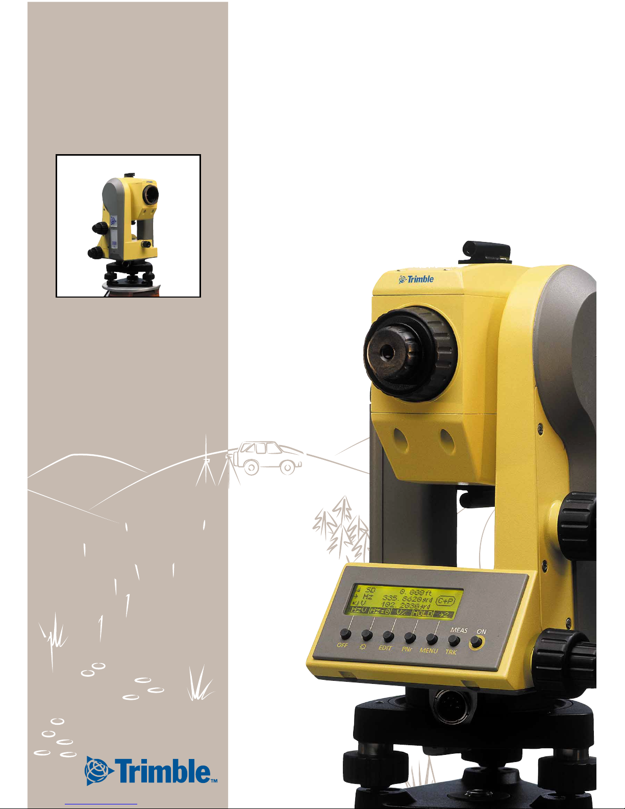
Trimble 3300
Topo Software User Guide
Part no.: 571 703 051
Page 2

Page 3

1
Contents
Dear Customer 1-2
The System Philosophy 1-3
Important Notes 1-4
Instrument Description
Hardware Overview........................................... 2-2
The Routine Total Stations Trimble 3300.......... 2-3
Overview about “Topo”..................................... 2-4
Overview about “Construction” ........................ 2-5
Operation
Software “Topo” ............................................... 2-6
The Keyboard..................................................... 2-8
The Basic Concept of the Menu........................ 2-9
Use of this Manual .......................................... 2-10
Safety Notes
Risks in Use ...................................................... 2-11
Attention .........................................................2-13
From Power to Data
Overview......................................................... 2-14
Before Measurement
Set-Up and Coarse Centring.............................. 3-2
Levelling and Fine Centring ............................... 3-2
Telescope Focusing............................................ 3-3
Switching the Instrument on............................. 3-4
Principles
Principles of Display........................................... 3-5
Principles of Input.............................................. 3-6
Input of Reflector, Trunnion Axis and
Station Heights.................................................. 3-7
Heightstationing Input of th and ih/Zs.............. 3-8
Measurement “Stationing in Elevation”............ 3-9
Input of Point Number and Code.................... 3-10
Principles of Distance Measurements..............3-11
Distance tracking.............................................3-11
Measurements to inaccessible Points ............. 3-12
1 Introduction
2 Trimble 3300 The Routine Total
Stations
3 First Steps
Page 4

2
Contents
Presettings
Introduction..................................................... 3-13
Settings in the Set-Up Menu........................... 3-14
Frequently used Settings.................................. 3-17
Instructions for Settings................................... 3-18
Saving the Measured Values ........................... 3-23
Measurement in the Start-Up Menu
Selecting the Measuring Mode....................... 3-24
Measurement .................................................. 3-26
The Menu Guidance
Principle ............................................................. 4-2
Station Point Memory Trimble 3300 ................ 4-4
Special Features of Trimble 3306 ...................... 4-4
Unknown Station
Stationing in Elevation....................................... 4-6
Measurement „Unknown Station“.................... 4-8
Recording......................................................... 4-10
Known Station
Measurement „Known Station“...................... 4-11
Orientation using a known Azimuth............... 4-12
Orientation using known Coordinates............4-13
Recording......................................................... 4-14
Stationing in E levation
Measurement „Stationing in Elevation“..........4-15
Recording......................................................... 4-17
Polar Points
Confirmation of Stationing..............................4-18
Measurement „Polar Points“...........................4-20
Eccentric Measurement...................................4-21
Recording......................................................... 4-22
Setting Out
Confirmation of Stationing..............................4-23
Measurement „Setting Out“ ........................... 4-25
Setting Out using known nominal
Coordinates ..................................................... 4-25
Setting Out using known Setting Out
Parameters....................................................... 4-26
Measurement Results ......................................4-27
Recording......................................................... 4-28
4 Coordinates
Page 5

3
Contents
The Menu Guidance
Principle ............................................................. 5-2
Connecting Distance
Measurement „Connecting Distance“............... 5-5
Polygonal Connecting Distance......................... 5-7
Radial Connecting Distance............................... 5-8
Recording........................................................... 5-9
Object Height
Measurement „Object Height“........................ 5-10
Definition of a Reference Height ZSet ............. 5-11
Measurement beside the Plumb Line..............5-12
Recording......................................................... 5-13
Station + Of fset
Measurement „Station + Offset“ ................... 5-14
The Station equals Point A .............................. 5-18
The Station equals Point B............................... 5-19
The Station equals Point P............................... 5-19
Shifting the Coordinate Axes y,x ..................... 5-20
Recording......................................................... 5-22
Vertical Plane
Measurement „Vertical Plane“ ........................5-23
hSet - Determination of the
Height Coordinate........................................... 5-24
xSet - Definition of the x-Axis .......................... 5-25
ySet - Points before or behind the Plane........ 5-26
The Station equals Point P............................... 5-27
Recording......................................................... 5-27
Area Calculation
Measurement “Area Calculation” ................... 5-28
Recording......................................................... 5-31
5 Applications
Page 6

4
Contents
Editor
Calling the EDIT Menu....................................... 6-2
Display of Data Lines.......................................... 6-2
Searching for Data Lines.................................... 6-3
Deleting Data Lines............................................ 6-4
Entering Data Lines............................................ 6-6
Data Transfer
Preparing the Instrument for data transfer ....... 6-9
PC Terminal Settings........................................6-10
Data Transmission ........................................... 6-11
Data Reception................................................6-12
Data Formats
Introduction..................................................... 6-13
Description of M5 data format .......................6-14
Description of Rec 500 data format................ 6-18
Description of R4 and R5 (M5, Rec 500)
format of Trimble 3300................................... 6-20
Defination of type identification......................6-26
Type identifier-CZ Formats M5, R4, R5
and Rec500 Trimble 3300 .............................. 6-26
Description of value blocks.............................. 6-29
CZ Format ID and address block...................... 6-30
Data output on a printer.................................6-31
User Interface
Introduction..................................................... 6-32
What is an interface?....................................... 6-32
Hardware interface.......................................... 6-33
Remote Control
Introduction..................................................... 6-34
Xon/Xoff Control ............................................6-34
Rec 500 Software Dialog
(Rec 500 Protocol)
.....6-34
Key Codes and Function Requests................... 6-36
Recording Data Lines
Recording Data Lines 6-41
Update
Introduction..................................................... 6-46
Preparation on the PC...................................... 6-48
Starting Update............................................... 6-50
6 Data Management
Page 7

5
Contents
Introduction 7-2
V Index / Hz Co ll imat i on 7-5
Compensator 7-6
Overview Softkeys 8-2
Overview Key Functions 8-6
Geodetic Glossary 8-7
Technical Data
Trimble 3304, 3306 and 3305........................ 8-13
Electromagnetic Compatibility ........................ 8-16
Battery Charger LG 20.....................................8-17
Charging the Battery........................................8-18
Formulae and Constants
Computational Formulae for
Angle Measurements ...................................... 8-19
Computational Formulae for
Distance Measurements.................................. 8-19
Reduction Formulae ........................................ 8-20
Verifying on Calibration Distances................... 8-22
Prism and Addition Constants.........................8-23
Error Messages
What to do......................................................8-24
Before you call the service ............................... 8-26
Maintenance and Care
Instructions for Maintenance and Care...........8-27
Case/Extended Temperature Range
Keeping the Measurement System
in the Case....................................................... 8-28
Using the Instrument in the Low Temperature
Range to -35°C................................................8-28
7 Adjusting and checking
8 Annex
Page 8

6
Contents
Page 9

1-1
1 Introduction
Dear Customer 1-2
The System Philosophy 1-3
Important Notes 1-4
Page 10

1-2
Introduction Dear Customer
Dear Cust omer
By purchasing an Trimble 3300 Routine Total
Station from Trimble you have opted for a leading-edge product in the fie ld of surv eying instru ments. We congratulate you on your choice and
would like to thank you for the trust placed in our
company.
Page 11

1-3
Introduction The System Philosophy
For quite some time, surveying has no longer
been limited to the measurement of bearings and
distances. Complex measurement systems have
been in demand that do not only satisfy ever increasing needs for automatiza tion, but als o those
involving digital data processin g as well as the
effectiveness of daily measuring practice. New
standards have thus been set regarding technology and operating convenience.
The Trimble 3300 Routine Total Station is part of a
complete range of surveying instru ments from
Trimble. Data interchange between all the instruments is ensured by a common da ta format.
The operating convenience offered by the Trimble
3300 hardware is very high within this group of
total stations. Th e clear graphic dis play and on ly 7
keys give the user a wide variety of information for
the processing in the field and provide him with
valuable aids for achieving high productivity in
solving his surveying tasks.
The software version “Topo
1
” meets high standards with the special programs for this a pplication.
1
topography
Page 12

1-4
Introduction Important Notes
The instrument was manufactured by tested
methods and using environ mentally compa tible
quality materials.
The mechanical, optical a nd electronic functio ns
of the instrument were carefully checked prio r to
delivery. Should any defects attributable to faulty
material or workmansh ip occur within the warranty period, they will be repaired as a wa rranty
service.
This warranty does not cover defects caused by
operator errors, inexpert handling or inappropriate
application.
Any further liabilities, fo r example for indirect
damages, cannot be accepted.
User manual: Edition
Cat. No.: 571 703 051
Date: February
FebruaryFebruary
February 2001
2001 2001
2001
Software releas e: >
> >
> V 5.50
Subject to alterations by the ma nufacturer fo r the
purposes of further technical development.
!
!!
! At
At At
Attention !
tention !tention !
tention !
Please read the safety notes in chapter 2
carefully before starting up the instrument.
Page 13

1-5
Introduction Important Notes
"
Phone: +49-6142-21000
Telefax: +49-6142-2100-220
E-mail:
Support@spectraprecision.de
Homepage:
http://www.trimble.com
#
##
# Tip
Tip Tip
Tip
The type label and serial nu mber are provided on the left-hand side and under-s ide of
the instrument, respectively. Please note
these data and the followin g information in
your user manual. Always indicate this reference in any inquiries addresse d to our dealer,
agency or service department:
Instrument:
$ Trimble 3303
$ Trimble 3305
$ Trimble 3306
Serial number: Software version:
A
Page 14

1-6
Introduction Important Notes
We would like to wish you every succes s in completing your work with your Trimble 3300. If you
need any help, we will be glad to be of assistance.
Yours
ZSP Geodetic Systems GmbH
Carl-Zeiss-Promenade 10
D-07745 Jena
Phone: (03641) 64-3200
Telefax:
(03641) 64-3229
E-Mail: surveying@zspjena.de
http://www.trimble.com
Page 15

2-1
2 Trimble 3300 - The Routine Total Stations
This chapter gives you an overview of the operation
and controls of the instrumen t as well as th e
programs which are a special featu re of the
Trimble 3300 Routine Total Stations.
Instrument Description 2-2
Operation 2-4
Safety Notes 2-9
From Power to Data 2-14
Page 16
2-2
Trimble 3300 Instrument Description
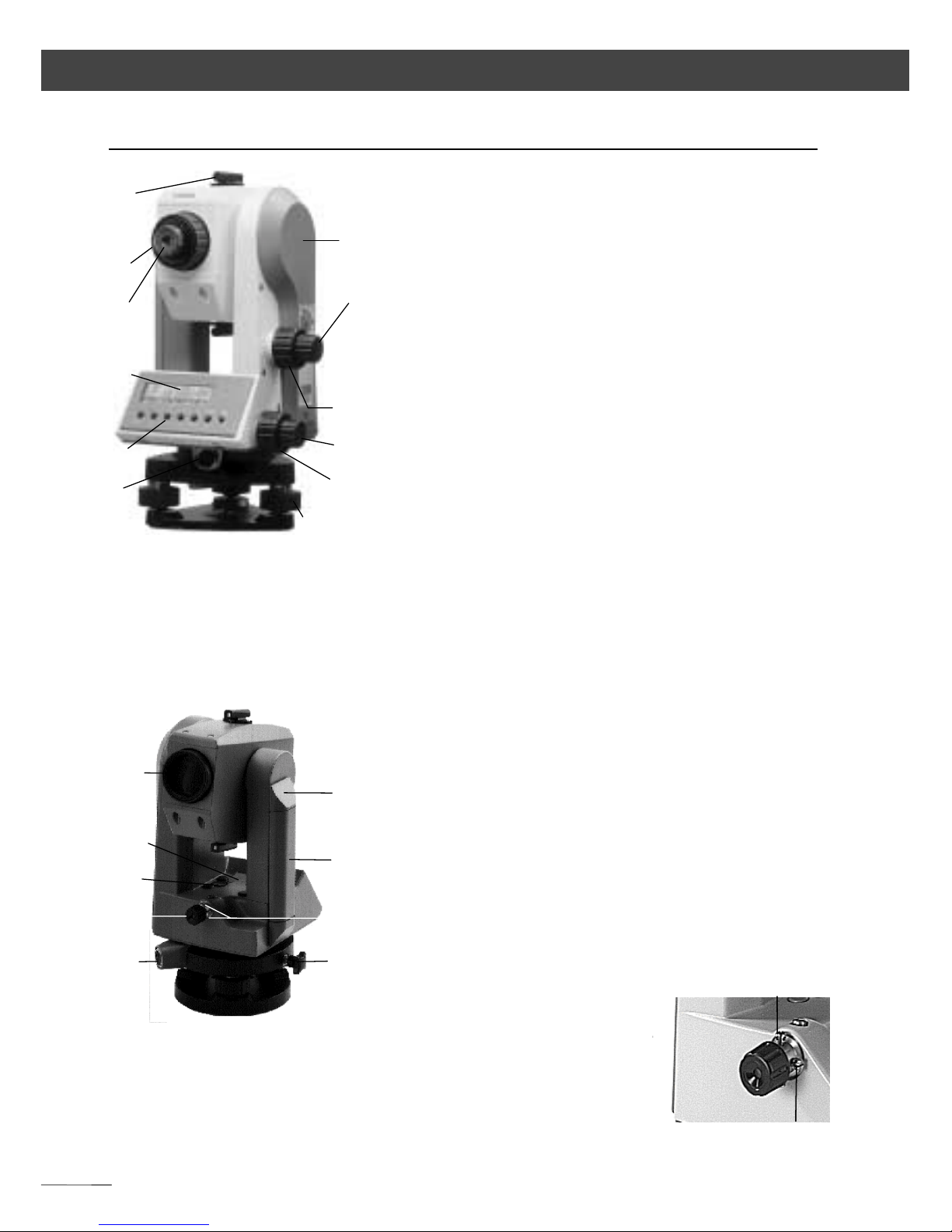
Hardware Overview
1 Sighting collimator
2 Mark for trunnion axis height
3 Telescope focusing control
4 Vertical tangent screw
5 Eyepiece
6 Vertical clamp
7 Display (graphic capabilities 128 x 32
pixels)
8 Horizontal tangent screw
9 Keyboard
10 Horizontal clamp
11 Interface
12 Tribrach screw
13 Telescope objective with integrated sun
shield
14 Battery cassette lock
15 Vertical axis level
16 Battery
17 Circular level
18 Adjustment screws for optical plu mmet
19 Optical plummet
20 Tribrach clamping screw
Fig. 1-1: Trimble 3303,
Control side
Fig. 1-2: Trimble 3300,
Objective side
1
2
3
4
5
6
7
8
9
10
11
12
Fig. 1-3: Trimble 3300,
Optical plummet
18
18
13
14
20
16
17
15
8
18
19
18
18
Page 17

2-3
Trimble 3300 Instrument Description
The Routine Total Stations Trimble 3303 / 3305 and Trimble 3306
The electronic Routine Total Stations as instruments
of mean accuracy are not only appropriate for
land-measuring by geodesists, but also users on
building sites appreciate their un complicated
handling as well as ra pidity, reliability and clea rness
in measuring.
Measurements are made easy thanks to menu
guidance supported by graphics , instrument
software with flexible point identification and
universal data record forma ts.
The principal features:
The principal features:The principal features:
The principal features:
by phase comparison method
Trimble 3303 up to 1500 m with 1 prism,
Trimble 3305 / 3306 up to 1300 m with 1 prism
Hz and V electronically
all common units and angle reference systems
Automatic compensation of sighting axis and index
errors
Display screen with graphic capabilities (128 x 32
pixels),
user-friendly surface, easy familia risation,
simple handling,
reliable control of all measu ring and compu ting
processes with clear references,
integrated, practical application pro grams,
ergonomic arrangement of controls,
light, compact construction
Eco-friendly power supply for about 1000 angle
and distance measurements, charging time 1 hour
RS 232 C (V 24) interface as data input and output
In the internal data memory of Trimble 3303 and
Trimble 3305, 1900 data lines can be saved.
Distance measurement
Measuring range
Angle measurement
Error compensation
The advantages in operating
Quick charging, longer
times of measuring
Data management
Page 18
2-4
Trimble 3300 Program versions
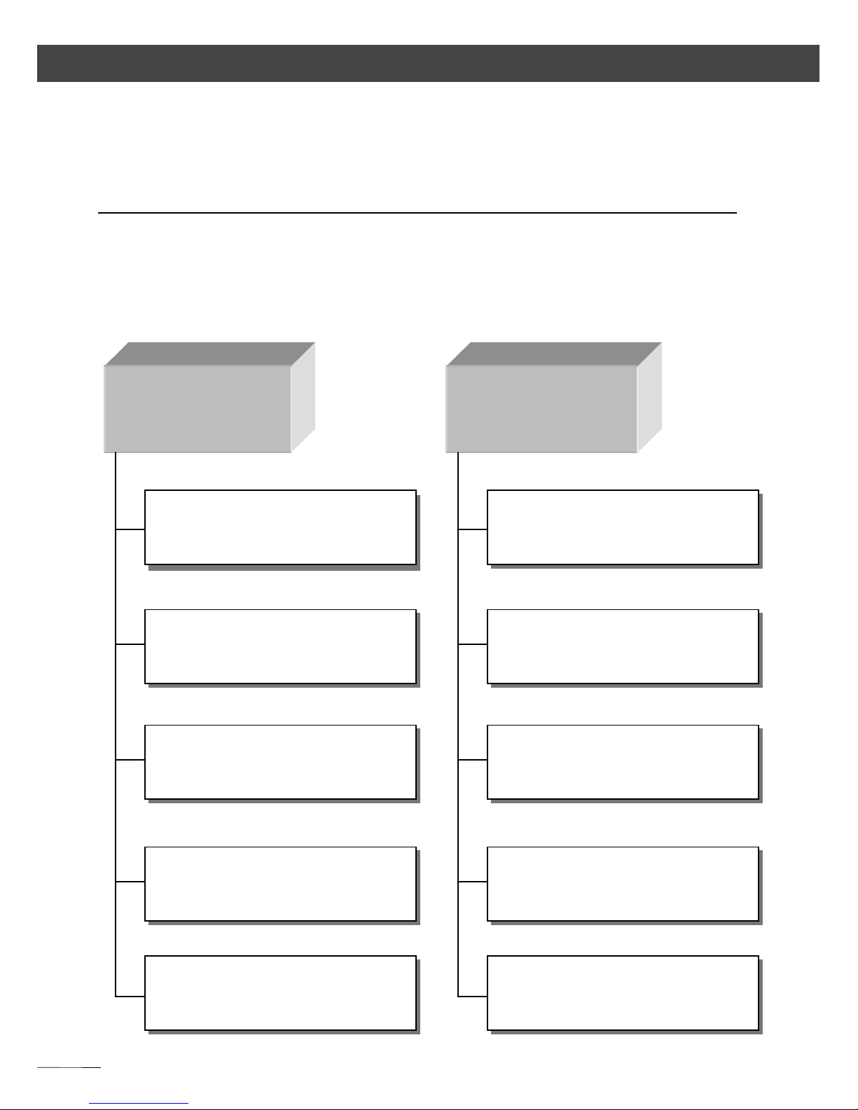
This program is availa ble on the delivered
instrument.
Overview about software versi on „T op o“
(version > 5.00)
Coordinate
programs
Application
programs
Connecting Distances
(with heightstatio ning – new)
Statio + Offset
(with heightstatio ning – new)
Object Height
Vertical Plane
Area Calculation
(new)
Unknown Station
(5 Bac ksi ght point - new)
Known Station
Heightstationing
Polar Points
(with eccentricity – new)
Setting Out
Page 19

2-5
Trimble 3300 Program versions
This program version can be selected.
Overwiev about software version „C onstruction“
(version > 4.00)
Coordinate
programs
Application
programs
Connecting Distance
(with heightstationing - new)
Station + Offset
(with heightstatio ning – new)
Object Height
Vertical Plane
Stake out Pt- Line
(new)
Stationing on a Known or
Unknown point
Heightstationing
Setting Out
Polar Points
Page 20
2-6
Trimble 3300 Operation
Overview about software “Top o”
Input
1
Addco
(addition constant)
2 Scale
3 Temp (temperature)
4 Pressure
Applications
1 Connecting distance
2 Object height
3 Station + Offset
4 Vertical plane
5 Area Calculation
Coordinates
1 Unknown Station
2 Known Station
3 Stationing in elevation
4 Polar points Determination
5 Setting out
Instrument setting
1 Angles (resolution)
2 Distances (resolution)
3 V reference
4 Coo system
5 Coo display
6 Temperature
7 Pressure
8 Switch off
9 Acoustic signal
10 Contrast
11 EDM T-Out
12 Angles (Units)
13 Distances (Units)
Menu (ON+MENU)
Page 21
2-7
Trimble 3300 Operation
Overview about software “Top o”
Interface
0 Record.
1 Format
2 Parity
3 Baud rate
4 Protocol
5 Position C
6 Position P
7 Position I
8 T-O Rec.
9 PC-Demo
Datentransfer
1 MEM -> Peripherie
2 Peripherie -> MEM
Update
Page 22
2-8
Trimble 3300 Operation
The Keyboard
For operating the Trimble 3300, only 7 keys are
needed.
Functions (Hardkeys)
Switching the instrument on and chan ging over to
hardkey function
Starting a measurement
Switching the instrument off
Illumination ON/OFF
Calling up the memory
Calling up the input of poin t number an d code
Going to the main menu
Starting the tracking function
Softkeys
Function keys defined by the display in depen dence
on the program.
Two types of keys:
! Hard keys
- direct function
ON
and
MEAS
- Key in connection
with
ON
(SHIFT)
! Sof tkey
function depending on
program, significance
explained in display line
at the bottom
ON
MEAS
ON
OFF
ON
✳
ON EDIT
ON PNo
ON MENU
ON TRK
#
Overview softkeys
Annex
OFF $ EDIT PNo MENU TRK SHIFT
MEAS
ON
Page 23
2-9
Trimble 330 Operation
The Basic Concept of the Menu
The total station is a ble to realise a great va riety of
functions.
Functions needed directly during the measuring
process are accessible through the key functions.
The menu facilitates the access to many other
functions.
Having selected the menu, you can go to
submenus and you are offered available functions,
respectively:
e.g. settings
e.g. measurement programs
ON
MENU
Page 24
2-10
Trimble 3300 Operation
Use of this Manual
The manual is divided into 8 main chapters.
The subchapters have not been numbered. Clarity
and convenience are provided by a maximum of 3
structural levels, for example:
4 Coordinates
2 Coordinates Unknown St ation
Recording
The pages are divided into two colu mns:
Principal text including
! Description of measuring processes and
methods
- instrument operation and keys
-Trimble 3300 display / graphics
- drawings and large gra phics
- tips, warnings and techn ical informa tion
Measuring tasks are defined as follows:
given:
:
: :
: given values
meas.: :
: :
: measured values
requ.:
:
: :
: required/computed values
You will find a list of terms in the an nex (Geodetic
Glossary).
Functional text for
calling up
programs:
Softkeys and t heir
functions
# Cross references
to other chapters
Small graphics
Chapter
Section
Subsection
%
%%
% Tip
Tip Tip
Tip
for hints, special as pects and tricks
& Attention !
Attention !Attention !
Attention !
for risks or potential problems
'
''
' Technical Informatio n
Technical Informatio n Technical Informatio n
Technical Informatio n
for technical background information
4 Coordinates
3 Stationing in elevation
Mode
Page 25

2-11
Trimble 3300 Safety Notes
Risks in Use
Instruments and original accessories from Carl Zeiss
have to be used only for the intended purpose.
Read the manual carefully before the firs t use and
keep it with the instrument so that it will be rea dy
to hand at any time. Be sure to comply with the
safety notes.
&
&&
& Attention !
Attention ! Attention !
Attention !
• Don´t make any changes or repairs on the
instrument and accessories . This is a llowed
only to the manufacturer or to specialist sta ff
authorised by the same.
• Only the service team o r authorised
specialist staff are allowed to open th e
instrument and accessories .
• Do not point th e telescope directly at the
sun.
• Do not use the instrument and accessories
in rooms with danger of explosion.
• Use the instrumen t only within the
operative ranges and conditions defined in
the chapter of technical data.
• Do not o perate th e battery ch arger in
humid or wet conditions (risk of electrical
shock). Make sure the voltage setting is
identical on the battery charger an d voltage
source. Do not use instruments while they are
wet.
Page 26

2-12
Trimble 3300 Safety Notes
&
&&
& Attention !
Attention ! Attention !
Attention !
• Take the necessary precautions at your
measuring site in the field, note the relevant
traffic rules.
• Check that the instrument has been
correctly set up and the accessories are
properly secured.
• Limit the time of working when it is raining,
cover the instrument with the protective
hood during breaks.
• After taking the instrument out of the case,
fix it immediately to the tripod with the
retaining screw. Do never lea ve it un fasten ed
on the tripod plate. After loosening the
retaining screw agai n, put the instrume nt
immediately back into the case.
• Prior to starting o peration, a llow sufficient
time for the instrument to adjust to th e
ambient temperature.
• Tread the tripod legs s ufficiently down in
the ground in order to keep the instrument in
stable position and to avoid its turn ing over in
case of wind pressure.
• Check yo ur instru ment at regular inte rvals in
order to avoid faulty measurements,
especially after it has been subjected to s hock
or heavy punishment.
• Remove the battery in case of being
discharged or for a longer stop period of the
instrument. Recharge the batteries with the
LG 20.
• Properly dispose of the batteries and
equipment taking into account the applicable
national regulations.
Page 27

2-13
Trimble 3300 Safety Notes
Attention
&
&&
& Attention !
Attention ! Attention !
Attention !
•The mains cable and plugs of accessories have to be
in perfect condition.
• When working with the tachymeter rod near to
electrical installations (fo r example electric railways,
aerial lines, transmitting stations and others), there is
acute danger to life, independent of the rod material.
Inform in these cases the releva nt and auth orised
security offices and follow th eir instruction s. Keep
sufficient distance to the electrical in stallations .
• Avoid surveying during thunderstorms because of
lightning danger.
Page 28
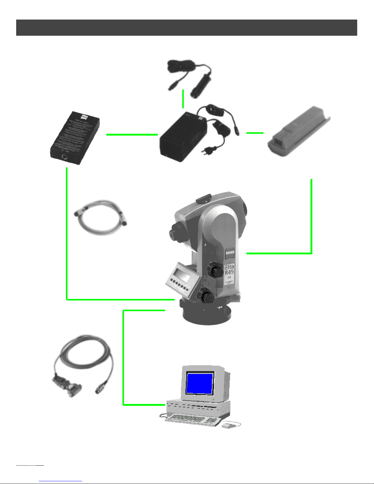
2-14
Trimble 3300 From Power to Data
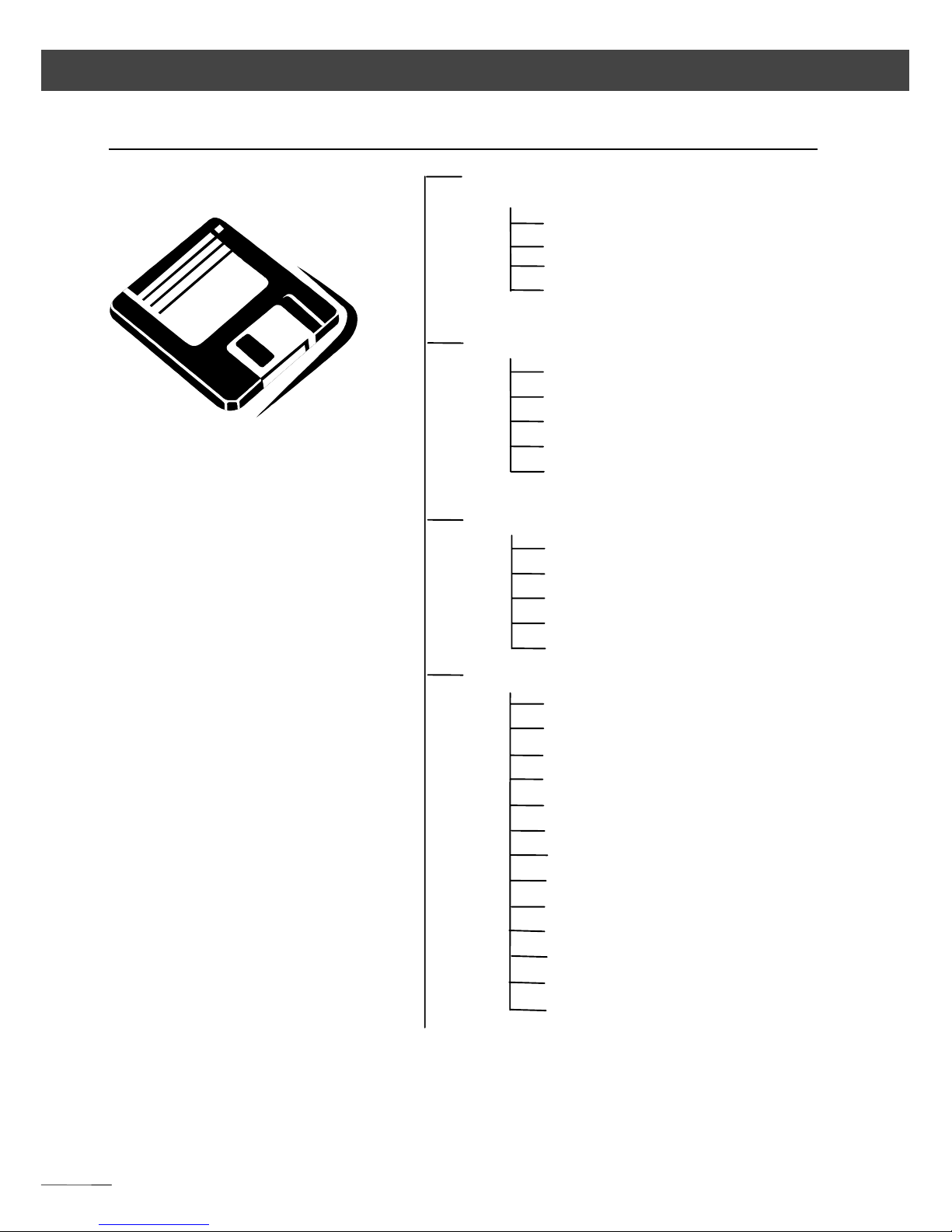
PC Station
LG20
230V: 708100
Charger 115V: 708103
External Battery 6V/7A h
708146-9901
only for Type „ -35
o
C “
Internal Battery
6 V1,1Ah
702504-9040
Car Adapter
for LG20: 708410
Power Cable 6V
708177-9480
Data Cable
708177-9460
Data Transfer Software
e.g. Terminal program
(Accessories / Windows)
Page 29

3-1
3 First Steps
The first steps cover up the set-up of the
instrument, including the explana tion of basic
inputs and the necessa ry presettings.
After having set the parameters for saving an d
entered the point information, you can measure in
the start-up menu.
Before Measurement 3-2
Principles 3-5
Presettings 3-13
Measuring in the Start-up Menu 3-24
Page 30
3-2
First Steps Before Measurement
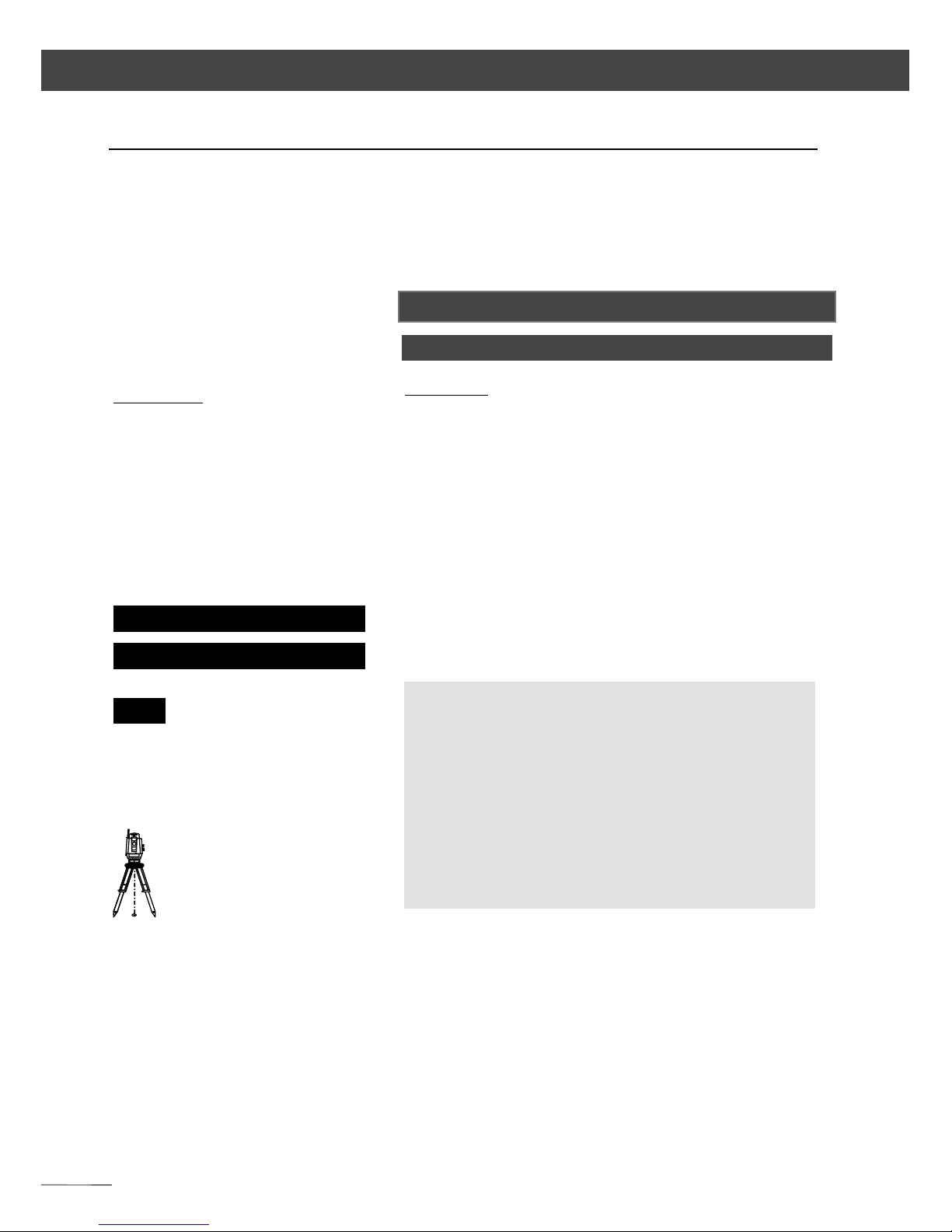
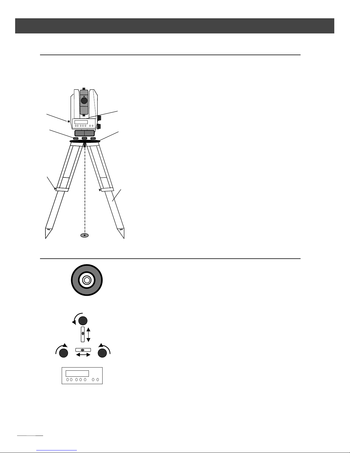
Set-Up and Coarse Centring
In order to guarantee the stability of meas urement
we recommend the use of a havy Tripod.
Set
SetSet
Set----up:
up: up:
up:
Extend the tripod legs (1) to a comfortable h eight
of observation and fix them using the tripod
locking screws (2). Screw the ins trument centrally
to the tripod head plate (3). The tribra ch screws (4 )
should be in mid-position.
Coarse Centring:
Coarse Centring:Coarse Centring:
Coarse Centring:
Set up the tripod roughly above the station point
(ground mark), the tripod head plate (3) should be
approximately horizontal.
Centre the circular mark of the o ptical plummet (5)
above the ground mark using the tribrach screws.
To focus the circle: Turn the eyepiece.
To focus the ground mark: Draw out or push in the
eyepiece of the optical plummet.
Levelling and Fine Centring
Coarse Levelling:
Coarse Levelling:Co arse Levelling:
Coarse Levelling:
Level the circular bubble (6) by adjustin g the length
of the tripod legs (1).
Precision Levelling:
Precision Levelling:Precision Levelling:
Precision Levelling:
Align the control unit pa rallel with the imagin ary
connecting line between two tribrach screws. Level
the instrument by tu rning the tribra ch screws a)
and b) in opposite directions. Turn the instrument
by 100 grad in Hz and level instrument with
tribrach screw c).For checking, turn the instru ment
round the vertical axis.
1
2
a)
b)
c)
1
2
4
3
5
6
Page 31

3-3
First Steps Before Measurement
After that, check the residual in clination by tu rning
the instrument in both diametral positions of (1)
and (2). Take the mean of deviation from center
point of level and adjust, if necess ary.
Precision Centring:
Precision Centring:Precision Centring:
Precision Centring:
Shift the tribrach on the tripod he ad plate until the
image of the ground mark is in the centre of the
circular mark of the optical plummet; repeat the
levelling various times if necessa ry.
Telescope Focusing
Focusing the Crosslines:
Focusing the Crosslines:Focusing the Crosslines:
Focusing the Crosslines:
Sight a bright, evenly coloured surface and turn the
telescope eyepiece until the line pattern is sha rply
defined.
Focusing the target point:
Focusing the target point:Focusing the target point:
Focusing the target point:
Turn the telescope focusing control until the target
point is sharply defined.
!
!!
! Attention !
Attention ! Attention !
Attention !
Sighting of the sun or strong light sources
must by all means be avoided. This ma y cause
irreparable damage to your eyes .
"
""
" Tip
Tip Tip
Tip
Check the telescope parallax: If you move
your head slightly whilst looking through the
eyepiece, there must be no relative movement
between the crosslines and the ta rget;
otherwise, refocus the crosslines as above.
Page 32

3-4
First Steps Before Measurement
Switching the Instrument on
Additionally to the company lo go, the number o f
the software vers ion (importan t for future updates )
and the values last set for:
- addition constant
- scale
- temperature
- air pressure
are displayed briefly.
ON
Press key
Switching the instrument
off by pressing the keys
ON
+
OFF
simultaneously.
"
""
" Tip
Tip Tip
Tip
The compensator is au tomatically activa ted
when the instrument is switched on.
If levelling of the instrument is insufficien t, the
digits after the decimal point in the displa yed
angle readings a re replace d by dash es.
Page 33

3-5
First Steps Principles
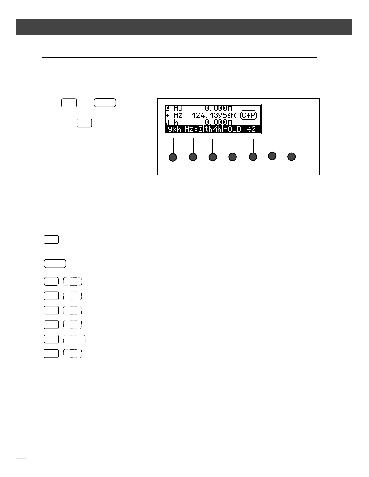
Principles of Display
Display page 2:
Display page 1:
The information
- point code,
- point number and
- measured / computed
values
is displayed on two pages.
Toggling between
the pages:
####
1
to page 1
####
2
to page 2
"
""
" Tip
Tip Tip
Tip
The fields at the bottom of the display are
related to the functions of the keys s ituated
below the display.
They indicate the next poss ible settings - do
not mix it up with the current setting.
Page 34

3-6
First Steps Principles
Principles of Input
Additionally to the setting of predefinitions - as
described further down in this ch apter - you will
have to enter data continually during the
measuring process.
These entries are
• the constantly changing instrument, station
and reflector height s and
• coordinates of stations or other known
backsight points.
The manual input of coordinates is described in
Chapter
ChapterChapter
Chapter 6
6 6
6 Data Management
Data ManagementData Management
Data Management.
If available, it is useful to trans fer the values directly
from a PC instead of entering them manually.
$
Editor
Data Management
$
Data Transfer
Data Management
Page 35

3-7
First Steps Principles
Input of Reflector, Trunnion Axis and Station Heights
on display page 1 only:
The input of the values of
reflector height (th),
instrument height (ih) and
station height (Zs) (heightstationing) allows you to
measure with absolute
heights already in the initial
menu. If these values have
not been entered, only
relative height differences
will appear in the display
(memory). If Zs=0 the
height difference “h” is
displayed and recorded,
otherwise the height “Z”.
th/ih
in measuring
modes HD and yxh
only
$
Presetting s
First Steps
ESC
to quit
Z
heightstationing
th
to enter the
reflector height
ih/Zs
to enter the
instrument and
station height
o.k.
to confirm
th
HD
h
SD
ih
Station
P
Z
Z
AP
Z
S
X/Y
Page 36

3-8
First Steps Principles
Heightstationing: Input of th and ih/Zs
Input of the reflector height:
Presentation of the current position for input in
negative type.
Input of the instrument height / station height
th 0.000 m
to confirm the old
reflector height
(in this case 0)
to enter a value
%%%%
and
####
to go to the desired
position in the
display
+
-
to browse through
digits
o.k.
to confirm
$
Editor
Data Management
to enter values
(compare input of
th)
ESC
to quit the input
routine
Page 37

3-9
First Steps Principles
Measurement „Stationing in E lev ati on“
Input one after the other:
Z, ih, th:
Measurement to the backsight poin t
Result and Recording
Stat
to go to the input
menus
CHCK
$
Adjusting and
checking
ESC
to quit the program
$
Principles
First Steps
$
Editor
Data Management
→→→→ sight to the
backsight point
ON
+
PNo
change of the point
number?
MEAS
YES
to accept the result,
to record data, to
left the program
NO
to quitt, new start
Page 38

3-10
First Steps Principles
Input of Point Number and Code
signalises th e possibility to en ter point
number and code.
The entered values will be used in the next
measurement.
CCCC 5-digit point code,
alphanumeric notation
PPPP 12-digit point nu mber with the special
characters #, -, . , .numeric notation
ON
+
PNo
%%%%
and
####
to go to the desired
digit of point
number and code
+
and
-
to browse through
the existing
character set
"
""
" Tip
Tip Tip
Tip
The toggling between point nu mber and
code is realised continuously.
For fast browsing, keep the respective key
depressed.
After the measurement, the point number is
incremented by one unit, the code remains
invariable until being modified by the user.
In the application and coo rdinate programs ,
the code is provided with non-varying
characters (A,B,..). In this case, it is not
possible to enter the code.
Page 39

3-11
First Steps Principles
Principles of Dis tance M eas urem ents
The intensity of the receiving signa l can be ass essed
with the bar graph. The more to th e right the stars
are presented, the better is the returning signa l.
The distance measurement can be cancelled with
the softkey ESC.
The slope distances and derived values are
corrected with regard to the influence s of ea rth
curvature / refraction. Additionally, a correction of
atmospheric influe nces (tempe rature a nd press ure)
is applied.
The correction is zero with T = 20°C and
P = 944 hPa.
Distance tracking (continuous measurement of the dis tance)
The measuring mode can also be changed during
the tracking measure ment. Fo r recording da ta
during the tracking measurement use key
MEAS
.
Single measurement
MEAS
$
Presetting s
First Steps
ON
TRK
END
to finish the
measurement
yxh
to change the
measurement mode
Page 40

3-12
First Steps Principles
Measurements to inaccessi b l e Points
The prism used for the distance measurement
cannot be stationed on the desired point P.
Sight towards the point P a nd trigger the
measurement. Then, sight the prism stationed on
the auxiliary point H.
Pay attention to the condition of equidistance
S-P = S-H.
If data recording is activ ated, on ly
a data line
indicating the angle to P and the dista nce to H is
saved.
Naturally, the angle and distance to H are
displayed after the measurement, being the angle
value continuously updated in the Trimble 3300
display.
"
""
" Tip
Tip Tip
Tip
Please use this function in the start-up menu
only.
In the program “Polar Points” it is possible to
measure with “Eccentric Measurement”.
Hz
SD
Station
P
i
H
Z,h
V
X,x
! S P = S H
Y,y
Page 41

3-13
First Steps Presettings
Introduction
The required presettings are to be subdivided into
three groups:
Settings in the Start-up Menu
• Specify measuring units for angle and distance
Short-time setting of V angle in percent
• Activating and dea ctivating the compens ator
• Orientation o f Hz circle
Frequently used Settings
• Input of press ure and temperature
• Input of scale and addition constant
Rarely used Set Instructio ns
• Display mode for a ngle and dis tance
• Vertical re ference s ystem
• System of coordinates
• Display of coordinates
• Measuring units of temperature, pressure
• Switching the in strument au tomatically o ff
• Switching the a coustic s ignal on and off
• Regulation of display contrast and brightness of
crossline illumination
• Switching the dista nce measuremen t off
automatically if sighting line in terruption
Page 42

3-14
First Steps Presettings
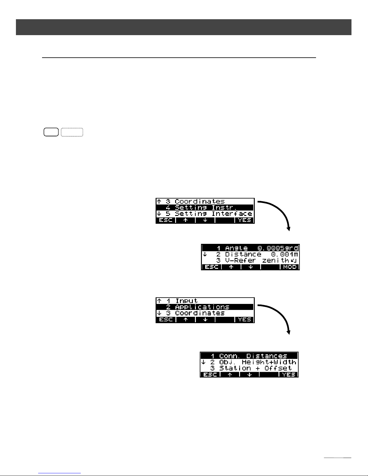
Settings in the Set-Up Menu
The settings of units for angle and distances are in
menu instrument settings. Distances settings can
be made in the measurement menu.
Display page 2
F1
F2
F3
F4
F5
Display page 1
Setting the measuring
units of distance
to set with
F1
the distance
m
meters
ft
feet
!
!!
! Attention !
Attention ! Attention !
Attention !
If the mode is changed after the
measurement, the values will be converted
and displayed in the new mode, but s aved in
this form only after the next measuremen t.
V%
V%V%
V%
V
&&&&
to toggle quickly
between angle in
percent / defined
measuring unit
Page 43

3-15
First Steps Presettings
If recording is activated, an informa tion line will
be saved indicating compensator function on or
off.
Activating and
deactivating the
compensator
Display page 2:
CHCK
to go to the menu
c/i
and
Comp
$
Adjusting and
checking
C-on
to deactivate the
compensator
function
C-off
to activate the
compensator
function
!
!!
! Attention !
Attention ! Attention !
Attention !
If the compensator is out o f its working ran ge
and the function is activated, th e digits after
the decimal point in the angle readings are
replaced by dashes. In this case, the
instrument is not sufficiently levelled a nd a
remote release from a PC is not admitted.
Page 44

3-16
First Steps Presettings
Display page 2
Orientation of Hz ci rcle
Aim: Hz = 0
Hz=0
Sight target
MEAS
Aim: Hz = xxx,xxx
HOLD
Turn the instrument to the
desired Hz circle value
MEAS
Sight target
MEAS
Aim: Change counting
direction
####
Hz
Measurement
clockwise
%%%%
Hz
Measurement
anticlockwise
!
!!
! Attention !
Attention ! Attention !
Attention !
The set counting direction is only valid in the
start-up menu.
After the connection and in all programs, the
Hz counting direction is always set clockwise.
Page 45

3-17
First Steps Presettings
Frequently used Settings
Alteration of pressure, temperature, scale
and addition constant
Range of values
-30 oC < Temp. < 70 oC with ∆ 1 oC
-0,127mm < Ad dco < 0,127mm with ∆ 1 mm
0,995000 < Scale < 1,005000 with ∆ 1 ppm
440hPa < Press. < 1460 hPa with ∆ 4 hPa
1 Input
ON MENU
''''
and
((((
to go to the desired
menu point
o.k.
to confirm
+
and
-
to alter the addition
constant (scale,
temperature and
pressure) step by
step
o.k.
to confirm
"
""
"
Tip
TipTip
Tip
For the first starting, only temperature an d
pressure are entered.
If a prism with another prism constant than
-35 mm should be used permanently, also
this setting should be realised immediately.
(For calculating the constant see annex.)
$
Formulae and
constants
Annex
Page 46

3-18
First Steps Presettings
Rarely used Set Instructions
Angle and distance displa y
Possibilities:
Angle
grad 0,005-0,001-0,0005 (Trimbl e 3305 / 3306)
grad 0,005-0,001-0,0002 (Trimbl e 3303)
DMS 10“ - 5“ - 1“
deg 0,005
0
- 0,0010 - 0,00050
mil
Distance
m 0,01-0,005-0,001
ft 0,02-0,01-0,001
4 Setting the instrument
ON
MENU
YES
to go to
''''
and
((((
to select the menu
point
MOD
to change setting
ESC
to quit menus
''''
and
((((
to quit setting /
confirm change
!
!!
! Attention !
Attention ! Attention !
Attention !
The defined presentations of angle and
distance are related to the display.
Saving is realised with the highest possible
precision.
Page 47

3-19
First Steps Presettings
Vertical reference s ystem
V reference systems:
V
&&&&
Zenith angle
V
))))
Vertical angle
1: Zenith angle 2: Vertical angle
unit 400 grads unit 360°
V))))⊥⊥⊥⊥****
Height angle
3: Height angle
unit 6400 mil
MOD
to change setting
ESC
to quit menus
''''
and
((((
to quit setting /
confirm change
Examples
Examples
"
""
"
Tip
TipTip
Tip
The setting of the measuring unit % is done
in the set-up menu!
0
grad
90°
100
grads
300
grads
0°
180°
200
grads
270°
1600
mil
-1600
mil
0
mil 0mil
Page 48

3-20
First Steps Presettings
System of coordinates / display of coordinates
Assignment of coordinates:
Indication sequence: Y-X / X-Y E-N / N-E
Measuring units for pressure / temperature
Possibilities:
Temperature
o
C degrees centigrade
o
F degrees Fahrenheit
Pressure hPa hectopascal (or millibar)
Torr
inHg
MOD
to change setting
ESC
to quit menus
''''
and
((((
to quit setting /
confirm change
!
!!
! Attention !
Attention ! Attention !
Attention !
When the assignment of coordinates is
changed, the question for further use of the
internal station coordinates appears in the
display, calling the user’s attentio n to a
possible source of errors.
MOD
to change setting
ESC
to quit menus
''''
and
((((
to quit setting /
confirm change
X
Y
N
Y-X X-Y E-N
Page 49

3-21
First Steps Presettings
Switching the instrument o ff / acoustic s ignal
Possibilities:
Switching off 10 min - 30 min - OFF
Acoustic signal ON- OFF
Displaycontrast /Reticle illumina tion
MOD
to change setting
ESC
to quit menus
''''
and
((((
to quit setting /
confirm change
"
""
"
Tip
TipTip
Tip
Before the instrument will be switched off
automatically, a warnin g appears in dicating
that the instrument will be switched off
within one minute. This process can be
interrupted by pressing any key.
MOD
to change settings
ESC
to quit the menu
''''
and
((((
to quit settings / to
confirm alterations
"
""
"
Tip
TipTip
Tip
The adjustment of the contrast is only
possible with the display illumina tion
switched off. The adjustment of the Reticle
illumination is only pos sible with the displa y
illumination switched on.
Page 50

3-22
First Steps Presettings
Time out of Distance meter during interrupted
EDM
Settings of units for angles and distances
Possibilities:
Angles Grad 400.0000
DMS 360° 00‘ 00“
deg 360.0000°
mil 6400mils
Distances m Meters
ft Feet
MOD
to change settings
ESC
to quit the menu
''''
and
((((
to quit settings / to
confirm alterations
"
""
"
Tip
TipTip
Tip
This setting controls the time out of the
distance meter during th e EDM interruptio n.
MOD
to change settings
ESC
to quit the menu
''''
and
((((
to quit settings / to
confirm alterations
"
Tip
It is possible to change the units between
meters or feet in the start up menu.
Page 51

3-23
First Steps Presettings
Saving the Measured Values
MEM/x
MEM/xMEM/x
MEM/x - internal saving
(only Trimble 3303 and Trimble 3305)
V24/x
V24/xV24/x
V24/x - external saving through RS232 interface
Off
OffOff
Off - no saving
1111 - saving of measured values
2222 - saving of computed values
3333 - 1 and 2
ON
+
MENU
5 Setting Interface
YES
to go to the menu
MOD
to toggle between
MEM/1, MEM/2,
MEM/3
V24/1, V24/2, V24/3
OFF
ESC
to return to the
higher-order menu
!
!!
! Attention !
Attention ! Attention !
Attention !
These settings are valid in the programs
„Coordinates“ a nd „Applicatio ns“.
All values in the Start-up menu are
interpreted as meas ured value s (1).
$
Record data lines
Data Management
"
""
"
Tip
TipTip
Tip
The detailed depiction concerning the
question of which values are saved with
which type identifiers and with which
recording selection you can find in the
chapter Data Management.
Page 52

3-24
First Steps Measurement in the Start-Up
Selecting the Measuring Mode (presentation of the results at the
display)
Display page 1:
SD: Display of the real measured values
F1
F2
F3
F4
F5
HzV: Display in the theodolite mode
$
Presetting s
First Steps
!
!!
! Attention !
Attention ! Attention !
Attention !
In connection with the selection of saving, the
selection of the measuring mode is decis ive
for:
Which results are to be displayed?
Which values are to be saved?
F1
to set the following
measuring modes
"
""
"
Tip
TipTip
Tip
In the display of softkey 1, a lways the n ext
selectable measuring mode appears.
Status display:
Only for alignments and for
setting out right angles, not
for distance measurements
Page 53

3-25
First Steps Measurement in the Start-Up
HD: Display of the reduced distance and th e height
difference
yxh: Display of the local recta ngular coo rdinates
Display of the calculated
values
with Z=0
with Z≠0
Measurement in the local
system with station y=x =0
with Z=0
with Z≠0
"
""
"
Tip
TipTip
Tip
The measuring modes can be changed at any
time and the results will be displayed
immediately in the selected measuring mode,
but not, though, another recording. All
following measurements are displayed and
recorded in the newly selected mode.
In all measuring modes, the a ngle reading is
updated continually.
The distance or coordinates are updated only
after the next measurement.
Page 54

3-26
First Steps Measurement in the Start-Up
Measurement
After entering and de fining all pa rameters re quired
you can carry out the measurement.
Display with absolute heights, with the heights Zs,
ih and th entered
MEAS
etc. Measurement to
further points
ON
+
PNo
Input
point number and
code
MEAS
"
""
"
Tip
TipTip
Tip
After the measurement, the flush righ t point
number is incremented by one unit within the
number of digits displayed up to the specia l
character (no figure) to the left of it.
(According to this picture, counting goes only
up to 9, then it will begin again with "0 ".)
Measurements in the modes
HzV
and
SD
are realised
without entering and
recording local or global
heights
Page 55

4-1
4 Coordinates
The basic requirement for a measurement in a
system of coordinates is a stationing within this
system. That means, that the position and height
of the instrument are determined by measuring to
known backsight points.
In the case of an unknown station, the scale and
the orientation of the Hz circle in azimuth directio n
are computed additionally to the station
coordinates. In the case of a known station, only
the scale and the orientation of the Hz circle in
azimuth direction are computed.
After the stationing, the actual measurements that means setting out and polar points - are
possible within this system of coordinates.
The Menu Guidance 4-2
Unknown Station 4-6
Known Station 4-11
Stationing in Elevation 4-15
Polar Points 4-18
Setting Out 4-23
Page 56

4-2
Coordinates The Menu Guidance
The guidance through the menu is very easy to
understand and based on a unique schema for all
programs.
Principle
Each program flow is demonstra ted by a graphics .
A and B are backsight poin ts with known
coordinates and S is the station the coordinates of
which are to be calculated.
Coordinates are to be entered
CHCK
!
Adjusting and
Checking
A
to call point A
"
""
" Tip
Tip Tip
Tip
The function of adjusting and checking is
required for measurements to be carried out
without/with compensator or for checking
the adjustment of the instrument.
!
Principles
First steps
!
Editor
Data management
Coordinates
Unknown station
Page 57

4-3
Coordinates The Menu Guidance
If A has been calculated, measu red, defined as
station, the symbol for A is filled.
B
to continue by
calling point B
ESC
to return to the
higher-order menu
A
to repeat point A
if required
#
##
# Attention !
Attention ! Attention !
Attention !
If errors or confusions should occur whilst
measuring to the points, the meas urement to
single points can be repeated immediately.
ON
+
PNo
to enter point
number and code
MEAS
to trigger
measurement
"
""
" Tip
Tip Tip
Tip
Prior to each measurement with
MEAS
it is
possible to enter a point nu mber and a code
for the point to be measured.
In the stationing programs, the codes (A, B, S)
have been invariably set. Point numbers can
be entered.
The point number is incremented
automatically by 1.
The code that has been set is saved with every
measurement until being modified by the
user.
In the setting-out program,
the possibility to measure is
indicated additionally by the
symbol in the display
Page 58

4-4
Coordinates The Menu Guidance
Station Point Memory Trimble 3300
In a non-volatile instrument memory, the following
data are retained after switching th e instrument off
and overwritten with every new determination:
Station coordinates Y,X,Z
Instrument height ih
Reflector height th
Scale m
Orientation Om
The coordinates of the station point are calculated
or entered by means of the coordination
programs.
During the following operations (setting-out / polar
points), the user can access this memory at the
respective parts of the program and does not have
to enter the values again.
After having changed the station, these values
have to be calculated or again entered in the
course of the program.
Special Features of Trimble 3306
The Trimble 3306 (the instrument is not fitted out
with a data memory) has a memory location for
another single point (coor-memory) containing the
coordinates of this point (Y;X;Z) in a non-volatile
form.
This memory location permits a simple
transmission of coordinates (stationing with
"unknown station") with the Trimble 3306 and
spares the user the trouble to take the coordina tes
down or to enter them twice.
Page 59

4-5
Coordinates The Menu Guidance
Window of the Trimble 3306 when calling
coordinates
Method:
The station coordinates S1 are known or have been
calculated by means of a coordinate program. The
coordinates of point K1 will be calcu lated with the
program „polar points“ a nd saved in th e „coor-
memory“ with
.
After placing the instru ment on S2, th e
coordinates of the points S1 (last station) and K1
(coor-memory) are called with the stationing
program "unknown station" and used for
determining the coordinates of S2.
Now, the coordinates of the point K2 can be
calculated with the program "po lar points" a nd
stored in the "coor-memory". After changing the
position of the instrument to S3, the coordinates
of this point will be calculated in a nalogy to sta tion
S2.
S1
S2
S3
K1
K2
K3
-
Station pt.
- Auxil. pt.
Trimble 3300
Principle
of transmission of
coordinates
„
unknown station"
Page 60

4-6
Coordinates Unknown Station
given: : (Y,X,Z)
A....E
meas.: : (SD,Hz,V)
S-(A-E)
requ.: : (Y,X,Z)
s
, Om , m
By measuring to 2..5 known BBBB
acksight PPPPoints
(AAAA.. EEEE), the instrument will calculate the sta tion
coordinates XXXX
SSSS
,YYYY
SSSS
,ZZZZ
SSSS
the circle orientation Om and
the scale m.
The description is "with stationing in elevation". The
procedure without stationing in elevation is almost
identical.
Stationing in Elevation
Input of instrument height
If it is not
possible to occupy
a point with a known
position in order to sight
the points to be surveyed or
set out, a free stationing can
be carried out.
If all backsight points have a
known height, the Z coordinate can also be determined
simultaneously. A maximum
of 5 points can be
measured!
ESC
to go to the
coordinates menu
with: input of
instrument height
without: no
calculation of
height
!
Principles
First steps
!
Editor
Data management
Coordinates
Unknown Station
Y
A
Y
Station unknown
BP AAAA
BP CCCC
X
X
A
X
B
YYYY
SSSS
Y
B
Y
A
Circle
Hz=0
Om
BP BBBB
BP DDDD
BP EEEE
X
D
Y
D
Page 61

4-7
Coordinates Unknown Station
Measurement „Unknown Station“
Selecting the coordinates of BP A
"
""
" Note
Note Note
Note !
! !
!
In a free stationing with height
determination, all backsight po ints must h ave
a height coordinate. It is not possible to use
individual backsight points separa tely
according to position a nd height.
The height is calculated by s imple averaging.
"
""
" Tip !
Tip ! Tip !
Tip !
If not all backsight points a re provided with a
height coordinate, the method without
without without
without
height
heightheight
height is to be applied. Subsequently, th e
station height can be determined separately
by measurement to one point using the
stationing in elevation program.
A
to select BP A
CHCK
!
Adjusting and
checking
ESC
to quit the program
!
Principles
First steps
!
Editor
Data management
Page 62

4-8
Coordinates Unknown Station
- Sight reflector
The operational steps for BP B....E are now carried
out in analogy to BP A.
Explanation:
vy: Residual in Y-direction
vx: Residual in X-direction
vz: Residual in Z-direction
th
to enter data for BP
A
ON
+
PNo
Point number of BP
A to be changed?
MEAS
to measure to BP A
B
to select BP B
A
Measurement to BP
A to be repeated?
After at least 2
measurements, approxim ate
coordinates are calculated
by software and the
deviation to the current
measurement is displayed.
ESC
to quit the program
B
Measurement to BP
C to be repeated?
C
to measure the next
point (E=5.)
END
to display the
residuals
#
##
# Tip !
Tip ! Tip !
Tip !
Consequently, residuals can also be used to
"stake out" (seek) points, because the
measurement of point can be repeated
immediately.
Page 63

4-9
Coordinates Unknown Station
Display of residuals:
Point to which the residuals belo ng
After confirming the residuals:
Display of the station coordinates:
Explanation:
m: calculated scale
Om: orientation unknown
s0: standard deviation of the weighting unit
(mean point error)
More
to measure
additional point
$$$$
,
%%%%
to select point
Del
to delete point
o.k.
to display station
coordinates
o.k.
to display further
parameters
ON
+
PNr
to enter the point
number of the
station
Wdhl
to repeat the
complete
determination
m
to edit the scale
o.k.
to accept the
coordinates,
complete the
program and go to
the coordinates
menu; to record
"
""
" Note !
Note ! Note !
Note !
It is possible to go backwards a nd re-measure
the corresponding points, whereby the
intermediary points get lost.
But it is more recommendable to complete
the measurement (calling the residua ls) after
three backsight points, delete and re-mea sure
the correspondin g direction. Ne w
measurements are added at the end.
Consequently, the assignment of the point
codes (A, B, etc.) are shifted.
Page 64

4-10
Coordinates Unknown Station
Scale menu
If the scale is outside the permissible range, an
error message a ppears.
Recording
If recording is activated, the following lines a re
saved in dependence on the settings:
Designation of the mode
Point numbers and code
backsight point A, B, C, D, E
Y,X,Z Coordinates
SD,Hz,V Readings
vy,vx,vz backsight point residuals
Y,X,Z Coordinates of station point S
m,Om Scale and circle orienta tion
s0 Standard deviation of the weight unit
-
scale
+
to edit
to accept scale, to
go to the residuals
menu
"
""
" Note !
Note ! Note !
Note !
After the scale has been confirmed, the
station coordinates are re-calculated. Then,
the residuals can be evaluated once more.
!
Presetting s
First steps
o.k.
Page 65

4-11
Coordinates Known Station
given: : (Y,X)
S,A
meas.: : (SD,Hz)
S-A,
or (Hz,V)
S-A
requ.: : Om , m or Om
By measuring to a known BBBB
acksight PPPPoint AAAA, the
instrument will calculate the circle orienta tion Om
and the scale m.
Measurement „Known Station“
Selecting the coordinates of station S
If it is possible to occupy a
point with a known posit ion
in order to sight the points
to be surveyed or set out, a
stationing on a known point
can be carried out.
S
to call station S
CHCK
!
Adjusting and
checking
ESC
to quit the program
!
Principles
First steps
!
Editor
Data management
Coordinates
Known Station
AA
Station known
BP
X
X
A
X
S
Y
Y
A
Y
S
Circle
Hz=0
Om
Page 66

4-12
Coordinates Known Station
After defining S:
There are two ways to calculate the orientation.
Orientation using a known Azimuth
The orientation us ing a known azimuth will be
selected if the bearing angle between the station
and the backsight point is kn own (for example
calculated from coordinates) a nd a distan ce
measurement to the backsight poin t is impossible.
Display of results an d recording
Hz
see below
XY
page 4-11
S
to repeat station S
to set the required
direction by turning
the instrument
MEAS
to clamp the set
direction
→→→→ to sight the known
point
MEAS
allocation is
completed
YES
to confirm, record,
quit the program
NO
to reject, new start
Page 67

4-13
Coordinates Known Station
Orientation using known Coordinates
This orientation method will be used if the
coordinates of the backsight point are known.
Selecting the coordinates of BP A
!
Principles
First steps
!
Editor
Data management
SD/Hz/V
Distance and
bearing
measurement
Hz/V
Bearing
measurement
ON
+
PNo
Point number of BP
A to be changed?
MEAS
to BP A
YES
to confirm the
orientation,
continuation
NO
to reject the
orientation,
new start
Page 68

4-14
Coordinates Known Station
Display of results an d recording
Recording
If recording is activated, the following lines a re
saved in dependence on the settings:
Designation of the mode
Point numbers and code
Y,X Coordinates of station point
Y,X Coordinates of backsight point A
SD,Hz,V Readings for backsight point A
according to s election
m,Om Scale and circle orienta tion
according to s election
new
to accept the new
scale
old
to transfer the
orientation
accepting an old
scale
Inpt
to transfer the
orientation entering
any scale
Rept
to repeat the
calculation
!
Presetting s
First steps
Page 69

4-15
Coordinates Stationing in Elevation
given.: : Z
P
meas.: : (SD,V)
S--P,
ih, th
requ.: : Z
s
The station height is determined by measurement
to a BBBB
acksight PPPPoint with a known height.
Measurement „Stationing in E lev ati on“
Stationing in elevation
permits the determinat ion
of the height above Mean
Sea Level independently of
planimetric stationing. In
programs involving local
coordinates, in particular,
the absolute height can be
included in the
measurement.
Stat
to go to the input
menus
CHCK
!
Adjusting and
checking
ESC
to quit the program
Stationing in elevation
X/Y
Reflector
ZZZZ
V
HD
BP
S
SD
Z
P
Z
S
Z
i
h
th
ih
Coordinates
Page 70

4-16
Coordinates Stationing in Elevation
Enter one after another:
Z, ih, th:
Example th:
Display of results an d recording
!
Principles
First steps
!
Editor
Data management
th 0.850 m
Confirmation of the
old value
th=0
Set to zero
→→→→ Sight backsight
point
ON
+
PNo
Point number to be
changed?
MEAS
YES
to confirm, record,
quit the program
NO
to reject,
new start
Page 71

4-17
Coordinates Stationing in Elevation
Recording
If recording is activated, the following lines a re
saved in dependence on the settings:
Designation of the mode
Point numbers and code
th Reflector height at backsigh t point
(only if chan ged)
ih Instrument height (only if changed)
Z Height of backsight point
SD, Hz, V Readings for backsight point
Zs New station height
!
Presetting s
First steps
Page 72

4-18
Coordinates Polar Points
given.: : (Y,X,Z)
,S
, Om, m
meas.: : (SD,Hz,V)
S-P
requ.: : (Y,X,Z)
P
Confirmation of Stationing
Determination of the
coordinates and heights of
new points by distance and
direction measurements.
The coordinates can be
computed in a higher-order
system of coordinates.
Local coordinates can be
determined in the standard
measurement menu.
YES
to confirm the
station coordinates
and to continue in
the program
NO
to reject, new start -
stationing
m
to change the scale
Coordinates
Polar Points
ZZZZ
Z
P
X
P
YYYY
V
XXXX
YP
Hz
HD
S
Reflector
SD
th
ih
Page 73

4-19
Coordinates Polar Points
Scale:
Reference direction:
Instrument and station heights:
+
,
-
to change m
o.k.
to confirm
YES
to confirm and
continue in the
program
NO
to reject, new start -
stationing
YES
to confirm and
continue in the
program
NO
to reject, new start -
height stationing
ih/Zs
to enter instrument
and reflector
heights
#
##
# Attention !
Attention ! Attention !
Attention !
If neither a stationing in elevation has been
realised beforehand nor Zs is entered now, all
heights Z will be related to the station height
Zs=0.
If ih is not entered either, all heights Z will be
related to the trunnion axis height Zi=0.
Page 74

4-20
Coordinates Polar points
Measurement „Polar Points“
Display of results and saving
&&&&1
,
&&&&2
to change pages
over
th
to enter the
reflector height of
the new point
ON
+
PNo
to enter point
number and code
of the new point
EXC
eccentric
measurement
CHCK
!
Adjusting and
checking
MEAS
to start the
measurement
"
""
" Tip
Tip Tip
Tip
The measurement can be triggered both on
display pages 1 and 2 .
After the measurement, the program return s
to the page where the measurement has
been triggered.
Page 75

4-21
Coordinates Polar points
Eccentric Measurement
The graphics does not change !
Type of target eccentricity (softkey
MOD
):
Tv: in front of the centre
Th: behind the centre
Tl: left of the centre
Tr: right of the centre
Ts: spatial relative to the centre
Viewing direction: Centre of the instrument !
Centre of the instrument !Centre of the instrument !
Centre of the instrument !
Display before eccentric measurement is sta rted
If points cannot be m easured directly, the eccentric
measurement option can
provide the solution. Spat ial
eccentric target
measurements are very
helpful especially for indoor
surveys.
Inp
to enter the length
MOD
to change the
mode
o.k.
to accept
ESC
to quit the menu
spatial eccentricity
position eccentricities
"
""
" Note !
Note ! Note !
Note !
Height calculation is ba sed on th e assumptio n
that centre and eccentricity have the same
level. This does of course not apply to the Ts
type (spatial) (calculation of the real height of
the centre).
"
""
" Note !
Note ! Note !
Note !
The eccentricity set is effective only once.
Tr
Tl
Tv
Th
Ts
Page 76

4-22
Coordinates Polar Points
Recording
If recording is activated, the following lines a re
saved in dependence on the settings:
Designation of the mode
Point numbers and code
m Scale (only if changed)
ih Instrument height (only if changed)
Zs Station height (only if changed)
th Reflector height at backsight point
(only if changed)
Tv,Th,Tr,Tl,Ts Eccentricity
SD, Hz, V Polar coordinates
Y, X, Z Rectangular coordinates
!
Presetting s
First steps
Page 77

4-23
Coordinates Setting Out
given.: : (Y,X)
S,P
comp.: :(HD,Hz)
S--P
meas.: : (HD,Hz,V)
S-N
comp.: : (dl,dq,dr)
P-N
Confirmation of Stationing
Search for or setting out
points in a given system of
coordinates. A stationing is
the prerequisite for setting
out points on the basis of
coordinates.
After having entered the
coordinates of the point to
be set out and measured
the approximate point, the
Trimble 3300 displays the
result in the form of the
longitudinal deviation dl,
the transverse deviation dq,
the angle Hz between the
approximate point and the
nominal point, the radial
deviation dr and the
deviations of the
coordinates dx, dy and dz.
YES
to confirm the
station coordinates
and to continue in
the program
NO
to reject, new start -
stationing
m
to change the scale
Coordinates
Setting Out
Y
Y
S
Station
P
(Set out point)
N
1 1.Näherungspunkt)
-dq
dl
dr
dx
dy
X
-Hz
X
S
N
2
(1st appr. point)
Page 78

4-24
Coordinates Setting Out
Scale:
Reference direction:
Instrument and station heights:
+
,
-
to change m
o.k.
to confirm
YES
to confirm and
continue in the
program
NO
to reject, new start -
stationing
YES
to confirm and
continue in the
program
NO
to reject, new start -
height stationing
ih/Zs
to enter instrument
and reflector
heights
Page 79

4-25
Coordinates Setting Out
Measurement „Setting Out“
The following options for the setting-out method
are available:
or
Setting out with or without height
Setting out using given coordinates
or
using known setting out parameters
Setting Out using known nominal Coordinates
CHCK
!
Adjusting and
checking
Z-n
,
Z-j
Change
with / without
height
YXZ
,
YX
see below
HDh,HD
page 4-26
!
Principles
First steps
!
Editor
Data management
Page 80

4-26
Coordinates Setting Out
After defining the coordinates:
to continue see measurement results
page 4-24
Setting Out using known Setting Out Parameters
Entering HD:
Defining the Hz value:
to turn the
instrument up to
Hz=0
th
to enter the
reflector height
ON
+
PNo
Point number and
code to be
corrected?
MEAS
to measure the
approximate point
HD 4.152 m
Confirmation of the
old value
HD=0
Set to zero
!
Principles
First steps
to set the desired
Hz value
MEAS
1st measurement to
the approximat e
point
Page 81

4-27
Coordinates Setting Out
Measurement results see below
Measurement Results
Display of results / recording
Additional measurement of the set out point:
Display of results / recording
ON
+
PNo
Point number and
code to be
corrected?
th
to enter reflector
height
&&&&
to change over the
different displays of
results
Test
see below
o.k.
to confirm the
setting out and
to record;
to set out other
points
MEAS
to repeat until the
approximate point
is close enough to
the set out point!
th
to enter the
reflector height
MEAS
to measure
Page 82

4-28
Coordinates Setting Out
Display of results an d recording
Recording
If recording is activated, the following lines a re
saved in dependence on the settings:
Designation of the mode
Point numbers and code
HD,Hz, Z or Nominal values
Y,X,Z
SD,Hz,V Readings for th e point
dl, dq, dr Setting-out differences
dy, dx Setting-out differences (only if
nominal coordinates are used)
dz Setting-out differences (only if
the height is set out)
or
th Reflector height
(only if changed)
SD,Hz,V Readings and
Y,X,Z Actual coordinates of check
measurement
S-O
Setting out, calling
up next point
!
Presetting s
First steps
Page 83

5-1
5 Applications
The chapter Applications describes typical
configurations and computations for various
measuring methods that are frequently used
in practice.
The Menu Guidance 5-2
Connecting Distance 5-5
Object Height 5-10
Station + Offset 5-14
Vertical Plane 5-23
Area calculation 5-28
Page 84

5-2
Applications The Menu Guidance
The guidance through the menu is very easy to
understand and based on a unique schema for all
programs.
Principle
In the Connecting Distance and Point-to-LineDistance programs, the height reference can be
established by a stationing in elevation (with) or by
a measurement to the first point (without).
The Object Height and Vertica l Plane progra ms
have own modes for a height reference.
After calling the respective program, a gra phics
appears with a detailed explanation of the
program.
with
!
Coordinates
Stationing in
Elevation
see page 4-15
without
to start the program
ESC
to quit the program
CHCK
!
Adjusting and
checking
A
to start the
program by calling
point A
Applications
Conn. Distances
Page 85

5-3
Applications The Menu Guidance
The display of AAAA in negative type indicates the
possibility to measure to point AAAA.
"
""
" Tip
Tip Tip
Tip
The function of adjusting and checking is
required for measurements to be carried out
without/with compensator or for checking
the adjustment of the instrument.
ON
+
PNo
to enter the
point number and
code
MEAS
to trigger measure-
ment
"
""
" Tip
Tip Tip
Tip
Prior to each measurement triggered with
MEAS
it is possible to enter a point nu mber
and a code for the point to be meas ured.
The point number is incremented
automatically by 1 without any need to lift a
finger.
In the programs, the codes for defin ed points
are invariably set (A, B, C, S) and cannot be
changed.
Page 86

5-4
Applications The Menu Guidance
If A has been calculated, measured or defined as
station, the symbol for A (squ are) is filled. Now, the
point B or P can be treated exactly the same way.
B
to continue in the
program by calling
point B
ESC
to return to the
higher-order menu
A
to repeat point A if
required
"
""
" Tip
Tip Tip
Tip
If errors or confusions should occur whilst
measuring to the points, the meas urement to
single points can be repeated immediately.
Page 87

5-5
Applications Connecting Distance
meas.: : (SD,Hz,V)
A,Pi
, th
requ.: : (SD,HD,h)
A-P
, (SD,HD,h)
P-P
, Zp
Measurement „Connecting Dis tance“
In measurements with stationing in elevation, the
height Z of the point is additiona lly displayed.
If it is not possible t o
measure a distance between
two points directly, the
measurement to these
points has to be started at a
station point S. Then, the
program calculates the
distances SD,HD and the
height difference h betw een
the points.
Examples for application:
Measurement of cross sections,
checking the distances between
points, boundaries and buildings
CHCK
!
Adjusting and
checking
A
to start by calling
point A
th
to enter the
reflector height of A
ON
+
PNo
MEAS
to measure to
point A
A=S
page 5-8
Applications
Connecting Distance
th
Pi
Pi
A
S
SD
A-P
SD
P-P
HD
A-P
HD
P-P
SD
A
SD
P
SD
ih
th
th
Page 88

5-6
Applications Connecting Distance
Display of results and saving
A
Measurement to
point A to be
repeated?
P
to call point P
th
to enter the
reflector height of P
ON
+
PNo
MEAS
to measure to
point P
P=S
page 5-8
"
""
" Tip
Tip Tip
Tip
After completing the determination of the
first connecting distance, there are two
different methods for continuing the
measurement:
polygonal measurement P-P or
radial measurement A-P.
The method can be changed at any time after
returning to the high er-order menu and
selecting again.
P-P
page 5-7
A-P
page 5-8
A
to repeat
measurement to
point A
DSP
to change over the
different displays of
results
Page 89

5-7
Applications Connecting Distance
Polygonal Connecting Distance P - P
The results are always rela ted to the last two po ints
measured.
Display of results and saving
th
to enter the
reflector height of
the next point P
ON
+
PNo
MEAS
to measure to
point P
Further points P:
th
,
ON
+
PNo
,
MEAS
Pi
Pi
Pi
A
S
Page 90

5-8
Applications Connecting Distance
Radial Connecting Distance A - P
The results are always rela ted to point A.
Display of results and saving
th
to enter the
reflector height of
the next point P
ON
+
PNo
MEAS
to measure to
point P
Further points P:
th
,
ON
+
PNo
,
MEAS
Pi
Pi
Pi
A
S
Page 91

5-9
Applications Connecting Distance
Recording
If recording is activated, the following lines a re
saved in dependence on the settings:
Designation of the mode
Point numbers and code
SD, Hz, V Polar coordinates A,P
th, ih Reflector height, instrument height
(only if changed)
SD, HD, h Connecting distance A-P or
SD, HD, Z Connecting distance A-P or
SD, HD, h Connecting distance P-P or
SD, HD, Z Connecting distance P-P
!
Presetting s
First steps
Page 92

5-10
Applications Object Height
meas.: : (SD,V,th)
A
, VP
requ.: : Z, HD, (O)
Measurement „Object Height“
Heights of inaccessible
points are determined by
measuring SD,V to an
accessible point in the
plumb line. Only the angle
V is measured to the
inaccessible point.
Examples for application:
Determination of tree heights,
widths of tree tops and trunk
diameters,
power lines,
passageways and bridge profiles,
setting out of heights on vertical
objects
CHCK
!
Adjusting and
checking
A
to start by calling
point A
th
to enter the
reflector height of A
ON
+
PNo
MEAS
to measure to
point A
Applications
Object Height
ZZZZ
xxxx
yyyy
P
A
SD
HD
Z
th
ZSet
Page 93

5-11
Applications Object Height
Measurement to point P
Display of results and saving
Definition of a Reference Height ZSet
With
ZSet
, a horizon with a given height can be
defined.
Display of results and saving
P
to call point P
ON
+
PNo
,
→ to sight point P
MEAS
to measure to
point P
further points P
Z 0.000 m
Confirming the old
reference height (in
this case 0)
!
Principles
First steps
ON
+
PNo
MEAS
to measure to the
reference height
Further points:
ON
+
PNo
,
MEAS
Page 94

5-12
Applications Object Height
Measurement beside the Plum b L i ne
to the left of the plumb line
to the right of the plumb line
Further points:
ON
+
PNo
,
MEAS
Further points:
ON
+
PNo
,
MEAS
O
ZZZZ
xxxx
yyyy
Page 95

5-13
Applications Object Height
Recording
If recording is activated, the following lines a re
saved in dependence on the settings:
Designation of the mode
Point numbers and code
SD, Hz, V Polar coordinates A
Hz, V Measuring poin t P
HD,O,Z Measuring point P
Z Set value Z
!
Presetting s
First steps
Page 96

5-14
Applications Station + Of fset
meas.: : (SD,Hz,V)
A,B,P
, th
requ.: : (x,y,ω)
P
, referred to the line A -B
h
A-B
, h
A-P
Measurement „Station + Offset“
Determination of the
rectangular coordinates of any
point in relation to a reference
line defined by the points A
and B.
Examples for application:
Checking of point distances from a
reference line,
checking of boundaries,
intersectio n of sigh t rails ,
determination of the distances of
buildings from boundaries,
footpaths or streets,
alignment of lo ng straigh t lines in
the event of visual obstacles on the
line,
surveying of supply lin es and
channel routes referred to roads
and buildings,
free stationin g in a loc al syste m
CHCK
!
Adjusting and
checking
A
to start by calling
point A
Applications
Station + Offset
S
Pi
ω
B
A
xxxx
---- y
y y
y
+ y
+ y+ y
+ y
SDp
SD
B
SD
A
ih
th
th
th
Page 97

5-15
Applications Station + Of fset
Display of absolute altitude Z (only with stationing
in elevation carried out)
Display of height difference h
th
to enter the
reflector height of A
DSP
to change over the
different displays of
results
ON
+
PNo
MEAS
to measure to point
A
A=S
page 5-18
B
to call point B
A
Measurement to
point A to be
repeated?
th
to enter the
reflector height of B
ON
+
PNo
MEAS
to measure to
point B
B=S
page 5-19
Page 98

5-16
Applications Station + Of fset
The results refe r to points A and B
Display of results and saving
Measurement to point P
The result can now be displayed in three different
modes.
Display of results and saving y, x, h
P
to call point P
B
B to be repeated?
A
A to be repeated?
th
to enter the
reflector height of P
ON
+
PNo
MEAS
to measure to
point P
P=S
page 5-18
DISP
to change over the
different displays of
results
CONS
to enter constants
for x and y
page 5-20
further points P
th
to enter the
reflector height of P
ON
+
PNo
MEAS
Page 99

5-17
Applications Station + Of fset
Display of results and saving x, y, Z
Display of results and saving x, y, ω
to change over the
different displays of
results
to change over the
different displays of
results
#
Attention !
Attention ! Attention !
Attention !
If the mode is changed after the
measurement, the values will be converted
and displayed in the new mode, but s aved in
this form only after the next measuremen t.
"
Tip
TipTip
Tip
Change the mode before the measurement.
DSP
DSP
Page 100

5-18
Applications Station + Of fset
The Station equals Point A A = S
Saving
!
Principles
First steps
YES
to confirm
NO
to reject
B
to continue in the
main program
 Loading...