

Trimble REF TEK Colt Broadband Seismometer, 117400-**-UG Series, REF TEK Colt 117400-60, REF TEK Colt 117400-120 User Manual
Page 1

REF TEK Colt™ Broadband
Seismometer User Guide
117400-XX-UG
Rev A
11/30/2018
This is the product user guide for the 117400-60 and 117400-120 Colt compact broadband
seismometer.
Trimble Inc.
5217 Tennyson Pkwy
Suite 400
Plano, Texas 75024
Support: 1-888-879-2207
Email: reftek_support@trimble.com
www.trimble.com/infrastructure
Page 2

Rev A REF TEK Colt™ Broadband Seismometer User Guide 11/30/2018
Rev
Date
Reason for Change
Pages
A
2018-11-30
Initial release
All
0.1
2018-10-26
Engineering Review
All
117400-XX-UG
Revision History
Legal Notices
Corporate Office
Trimble, Inc.
935 Stewart Drive
Sunnyvale CA 94085
USA
www.trimble.com
Copyrights and Trademarks
© 2018, Trimble, Inc. All rights reserved.
Trimble, and Globe & Triangle logo are trademarks of Trimble, Inc., registered in the United States and in
other countries.
All other trademarks are the property of their respective owners.
Product warranty information
For applicable product warranty information, please contact support.
Trimble Inc
5217 Tennyson Pkwy, Suite 400
Plano, Texas 75024
USA
Voice: 1-888-879-2207
Fax: 972-578-0045
EMAIL: MonSol_support@trimble.com
WWW: http://www.reftek.com
Supply the indicated information at time of contact.
Description of Problem
Type of Instrument
Model Number
Part Number
Serial Number
Trimble Inc. i
Page 3

Rev A REF TEK Colt™ Broadband Seismometer User Guide 11/30/2018
Notation
Description
ASCII
Indicates the entry conforms to the American Standard Code for Information Interchange definition of
character (text) information.
Binary
Indicates the entry is a raw, numeric value.
Hex
Indicates hexadecimal notation. This is used with both ASCII characters (0 – 9, A – F) and numeric values.
BCD
Indicates the entry is a numeric value where each four bits represents a decimal digit.
FPn
Indicates the entry is the ASCII representation of a floating-point number with n places following the
decimal point.
<n>
Indicates a single 8-bit byte. When the contents are numeric, it indicates a hexadecimal numeric value;
i.e. <84> represents hexadecimal 84 (132 decimal). When the contents are capital letters, it represents a
named ASCII control character; i.e. <SP> represents a space character, <CR> represents a carriage
return character and <LF> represents a line feed character.
MSB
Most Significant Byte of a multi-byte value.
MSbit
Most Significant Bit of a binary number.
LSB
Least Significant Byte of a multi-byte value.
LSbit
Least Significant Bit (bit 0) of a binary number.
YYYY
Year as a 4-digit number
DDD
Day of year
HH
Hour of day in 24-hour format
MM
Minutes of hour
SS
Seconds of minute
TTT
Thousandths of a second (milliseconds)
IIII
Unit ID number
n, ns
nano, nanosecond; 10-9 = 0.000000001
u, us
micro, microsecond; 10-6 = 0.000001
m, ms
milli, millisecond; 10-3 = 0.001
K, KHz
kilo, kilohertz; 103 = 1,000
M, MHz
mega, megahertz; 106 = 1,000,000
G, GHz
giga, gigahertz; 109 = 1,000,000,000
Kb, KB
kilobit, kilobyte; 210 = 1,024
Mb, MB
megabit, megabyte; 220 = 1,048,576
Gb, GB
gigabit, gigabyte; 230 = 1,073,741,824
WARNING
This alert warns of a potential hazard which, if not avoided, could result in
severe injury or even death.
CAUTION
This alert warns of a potential hazard or unsafe practice that could result in
minor injury or property damage or irretrievable data loss.
117400-XX-UG
Notation Conventions
The following notation conventions are used throughout REF TEK documentation:
NOTE: This is a note.
Trimble Inc. ii
Page 4

Rev A REF TEK Colt™ Broadband Seismometer User Guide 11/30/2018
117400-XX-UG
REF TEK Support and update notifications
As a valued user of REF TEK equipment we would like to provide the best support possible by keeping you
up to date with our product updates.
If you would like to be notified of any REF TEK product updates please spend a couple of minutes to
register with the REF TEK customer support team.
To register enter your company information through the Register link on our website at
http://support.reftek.com
Our support team will send you a unique Username and Password allowing secured access to all product
documentation and software sold to your company.
Once we register your contact we will only send necessary notifications via email. The same notifications
will be shown on our website’s http://support.reftek.com notifications page.
Support Phone: 1-888-879-2207
Support Email: reftek_support@trimble.com
Trimble Inc. iii
Page 5

Rev A REF TEK Colt™ Broadband Seismometer User Guide 11/30/2018
117400-XX-UG
Table of Contents
1 General Description ........................................................................................................ 6
1.1 Overview of the REF TEK Colt broadband seismometer ................................................................. 6
1.2 Sensor Operation .................................................................................................................................. 6
1.2.1 Sensor Topology ......................................................................................................................... 7
1.3 Specifications ........................................................................................................................................ 8
1.4 Installation, Leveling and Orientation ............................................................................................... 8
1.4.1 Leveling and Orientation Controls ........................................................................................... 9
2 REF TEK Colt Pre-Installation ...................................................................................... 10
2.1 REF TEK Colt Box Contents ................................................................................................................10
2.2 Checklist for working environment .................................................................................................10
2.3 Site Preparation ..................................................................................................................................10
2.4 Unpack the REF TEK Colt ...................................................................................................................11
3 Installation ..................................................................................................................... 13
3.1 Installation of the Colt .......................................................................................................................13
3.2 Powering up the REF TEK Colt ..........................................................................................................14
4 Checking Mass Position Voltage using a handheld device ...................................... 16
4.1 Use the Control menu to check the REF TEK Colt ..........................................................................16
4.2 Aux Channels .......................................................................................................................................16
4.2.1 Check the Mass Position Voltages .........................................................................................16
4.2.2 User Initiated Centering Operation .......................................................................................17
4.2.3 Use the Monitor function ........................................................................................................17
5 Checking Mass Position Voltage with RTCC .............................................................. 18
5.1 RTCC Status/Control Screen ..............................................................................................................18
5.1.1 To update the DAS status on the current screen .................................................................18
5.1.2 Auxiliary Channels ....................................................................................................................19
5.2 RT_Display Example ............................................................................................................................20
6 Connector Pinout .......................................................................................................... 21
7 General Description1 .................................................................................................... 22
7.1 UVW/XYZ Output Mode ....................................................................................................................22
7.2 Mass Position Centering ....................................................................................................................22
8 Calibration ..................................................................................................................... 23
8.1 Example: Sine Wave Calibration .......................................................................................................24
8.2 Example: Step pulse Calibration of the REF TEK Colt...................................................................24
9 Feedback System .......................................................................................................... 26
10 REF TEK Colt Transfer Functions ............................................................................... 27
10.1 Transfer Function for the 120 second REF TEK Colt (P/N 117400-120) ...................................27
10.2 Transfer Function for the 60 second REF TEK Colt (P/N 117400-60) .......................................28
10.3 REF TEK Colt Response Characteristics..........................................................................................29
10.3.1 Amplitude and Phase Characteristics for the 120s Colt ...................................................29
10.3.2 Amplitude and Phase Characteristics for the 60s Colt .....................................................30
Trimble Inc. iv
Page 6

Rev A REF TEK Colt™ Broadband Seismometer User Guide 11/30/2018
117400-XX-UG
11 Packing and Transportation ...................................................................................... 31
11.1 Warranty Statement .........................................................................................................................31
11.2 Warranty/Non-Warranty Service ...................................................................................................31
Trimble Inc. v
Page 7

Rev A REF TEK Colt™ Broadband Seismometer User Guide 11/30/2018
117400-XX-UG
1 General Description
1.1 Overview of the REF TEK Colt broadband seismometer
The REF TEK Colt™ is a force-balance feedback broadband sensor which features low
self-noise and a high dynamic range. The REF TEK Colt incorporates the following builtin functionality: automatic mass unlock after power up, automatic mass lock after loss of
power, analog mass position outputs, sensor calibration input, mass re-center upon user
command for remote mass centering, and lock/unlock upon user command. The REF
TEK Colt also incorporates built-in surge, lightning, and overvoltage protection on all
input/output pins.
The easy to use REF TEK Colt housing includes three adjustable leveling feet (each with a
locking nut), a bubble level, and several tools for easy alignment to North-South.
1.2 Sensor Operation
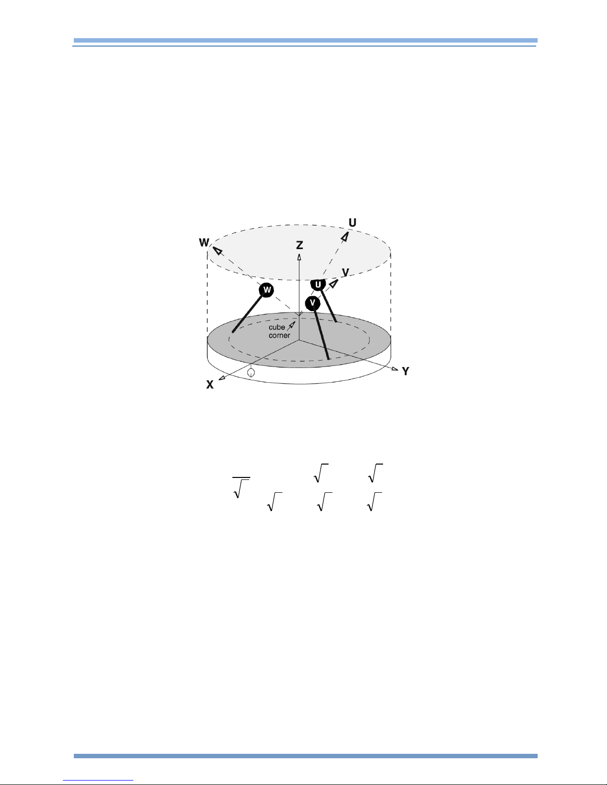
The REF TEK Colt uses a symmetrical axis topology as shown in Figure 1-1. With the
symmetrical topology, the REF TEK Colt uses three identical mechanical elements
mounted symmetrically onto the base of the unit. The REF TEK Colt’s analog output
signals are Z, Y, X orthogonal axis outputs. The Z output is the vertical output. The Y
axis output of the REF TEK Colt seismometer is the North-South output and the X axis is
the East-West output.
During normal operation the REF TEK Colt outputs are ZYX broadband sensor outputs.
During Mass Centering, Mass Unlocking, or Mass Locking the REF TEK Colt outputs are
switched into a short period ZYX output mode. During Calibration, while the Cal enable
signal is pulled low, the main signal outputs are switched to output the UWV signals
directly.
The REF TEK Colt has an internal super-capacitor which allows it to automatically lock its
masses anytime power is removed. When power is applied to the REF TEK Colt, it waits
two minutes for its internal mass lock super-capacitor to be fully charged. After the two
minute waiting period, the REF TEK Colt seismometer automatically unlocks its masses.
After the masses are automatically unlocked, the REF TEK Colt will automatically begin a
mass re-center cycle. This means that power can simply be applied to the REF TEK Colt
and after a few minutes it will have automatically unlocked itself, centered its masses
and be fully operational and outputting ZYX broadband seismometer signals.
Trimble Inc. 6
Page 8
Rev A REF TEK Colt™ Broadband Seismometer User Guide 11/30/2018
W
V
U
Z
Y
X
222
3- 30
1 1 2-
6
1
117400-XX-UG
Upon loss of power (including cable disconnection), the REF TEK Colt will automatically
lock the masses using power supplied by its internal super-capacitor. It is
recommended that the user manually lock the masses before powering off the unit
when moving or transporting the Colt seismometer.
1.2.1 Sensor Topology
The geometry of REF TEK Colt’s output coordinate system is shown below in Figure 1-1.
The conversion formula used to convert from the seismometers symmetrical (UVW)
orientation to its standard orthogonal (ZYX) output is show in Figure 1-2.
Figure 1-1 REF TEK Colt sensor topology
Figure 1-2 REF TEK Colt symmetrical to orthogonal output conversion formula
Trimble Inc. 7
Page 9

Rev A REF TEK Colt™ Broadband Seismometer User Guide 11/30/2018
Sensor Type
3 component Symmetrical
Feedback
Force balance with capacitive displacement transducer
Frequency Response
60s: 0.0167Hz (60 sec) - 80Hz (See Section 10)
120s: 0.0083Hz (120 sec) - 80Hz (See Section 10)
Sensitivity
2000 V/m/s (Differential output)
Output Signal
±20 V (Differential output)
Dynamic Range
Greater than >155 dB (1-10 Hz)
Output Impedance
Less than 100Ω
Calibration
Coil resistance 750Ω, sensitivity 10 m/s²/A
Leveling
Integrated bubble level
Adjustable leveling feet with locknuts (3)
Mass Position
Remote monitoring using 3 independent voltage outputs
Mass Locking
Automatic lock/unlock and upon user command
Distortion
Total distortion less than -60dB
Cross Axis Coupling
Less than 1%
Mechanical Zero
No need for adjustment in ± 20° C
Power-Fail Protection
Yes
Signal Overload Protection
Yes
Auto-recovery time
From Power Fail: ~10 Minutes
From Signal Overload: ~10 Minutes
Power Input
9 to 18 VDC
Operating Temperature
-25°C to +55°C
Power Consumption
<0.7 Watts
Water Tight Integrity
IP 67
Case
Aluminum, Powder Coated
Dimensions
Diameter 150 mm x Height 258 cm
Weight
5.5 kg
Connector
PT07A14-19S
117400-XX-UG
1.3 Specifications
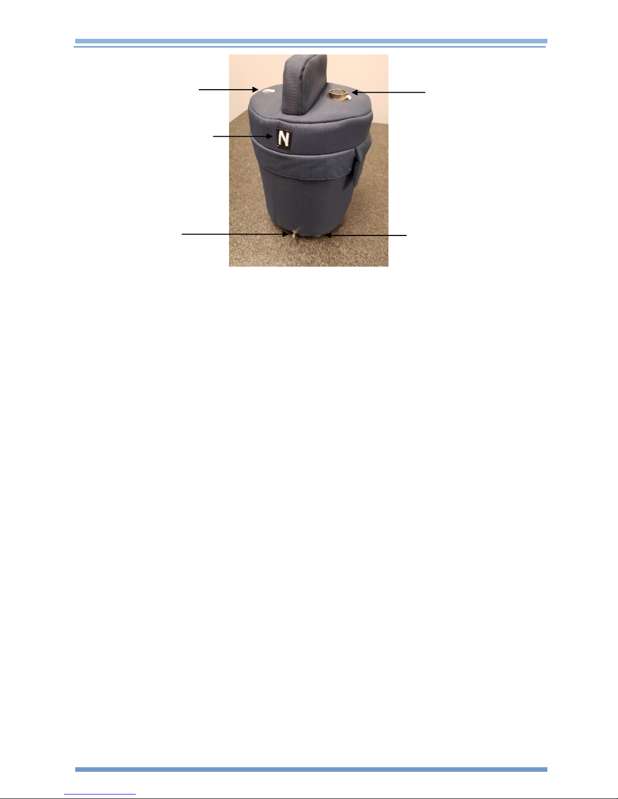
1.4 Installation, Leveling and Orientation
Leveling of the REF TEK Colt is accomplished by using the three adjustable leveling feet
at the base of the unit. Once leveled, each leveling foot includes a locknut that should
be locked to keep the unit from moving. Before leveling the unit, the unit should be
orientated to point North. The REF TEK Colt includes two removable North-South
pointers that can be installed into the base of the unit during orientation. Additionally,
the handle is aligned in the North-South direction. The thermal cover bag also has the
letter “N” embroidered onto it for easy reference of the North orientation.
Trimble Inc. 8
Page 10
Rev A REF TEK Colt™ Broadband Seismometer User Guide 11/30/2018
Bubble Level
North Orientation
Marker
Orientation Pin
Connector
Leveling Foot
117400-XX-UG
Figure 1-3 REF TEK Colt Orientation and Leveling
1.4.1 Leveling and Orientation Controls
See Figure 1-3 for reference.
Orientation
The orientation pins are used to orientate the seismometer in the North and South
direction. In addition, the handle on top of the unit is aligned North-South and can be
used to align the seismometer in the correct orientation.
Bubble Level
The Bubble Level is used to level the seismometer as adjustments are made to the
leveling feet.
Adjustable Feet
Three Adjustable Feet are provided to level the seismometer. Use the Locknut Ring to
lock each adjustable foot after the instrument is level.
Trimble Inc. 9
Page 11

Rev A REF TEK Colt™ Broadband Seismometer User Guide 11/30/2018
Item
Description
Part Number/Comment
1
REF TEK Colt Seismometer
117400-120 or 117400-60
1
Thermal Cover Blanket
Pre-installed on unit
1
Calibration sheet
Paper inside clear plastic sleeve
1
North and South Orientation Pins
Inside clear plastic sleeve
1
Connection Cable (Optional)
117440-00 for connection to 130S-01 (optional)
117400-XX-UG
2 REF TEK Colt Pre-Installation
The standard frequency response of the REF TEK Colt seismometer is either 0.0167 (60
sec) to 80 Hz (P/N 117400-60) or 0.00833 (120 sec) to 80 Hz (P/N 117400-120) so the
working environment should meet the requirements for accurate observation of short,
mid and long period seismic waves.
The seismometer needs to be placed in a location protected from the environment. Use
the following checklist to help determine and prepare the location before installation.
2.1 REF TEK Colt Box Contents
NOTE: Keep all packing material and instructions for shipping the
seismometer.
2.2 Checklist for working environment
The mounting surface should be clean (no loose material), close to level and well connected
to the bedrock.
The seismometer should be sheltered from wind and not exposed to direct sunlight.
The location for the seismometer should be thermally stable. A thermal insulated cover
(outside of the seismometer) can be used to attenuate temperature variation.
For better results, human activity around the seismometer should be minimized.
Magnetic sources should not be placed nearby because it may cause noise and interfere
with the normal observation of the seismometer.
Place the seismometer in a secure location.
2.3 Site Preparation
Prepare and clean the mounting surface so that it is free from any loose materials.
For best results, the installation site should protect the seismometer from temperature
extremes, vibrations from other equipment, and isolated from air currents.
The REF TEK Colt seismometer should be installed so that it is aligned and orientated
North to South. To facilitate this, it is recommended that the user mark a permanent (or
semi-permanent) scribe line onto the mounting surface before installing the REF TEK
Trimble Inc. 10
Page 12

Rev A REF TEK Colt™ Broadband Seismometer User Guide 11/30/2018
117400-XX-UG
Colt. The scribe line should run North -> South, be about 2 feet long and centered
approximately at the center of where the REF TEK Colt will be installed.
2.4 Unpack the REF TEK Colt
NOTE: Visually inspect the REF TEK Colt for any damage that may have
occurred during shipment.
1. Unpack the REF TEK Colt from its shipping box by removing the packing foam from the
top of the instrument. See Figure 2-1. Set aside the clear plastic folder, it contains the
orientation pins that will be used during installation.
Figure 2-1 REF TEK Colt Top Packing Foam
2. Gently remove the REF TEK Colt seismometer from the shipping box. Use the handle at
the top of the unit.
Figure 2-2 REF TEK Colt Unpacking
3. The shipping foam which holds the REF TEK Colt upright may come out of the box with
the seismometer see Figure 2-3. This is OK.
Trimble Inc. 11
Page 13

Rev A REF TEK Colt™ Broadband Seismometer User Guide 11/30/2018
117400-XX-UG
Figure 2-3 REF TEK Colt Unpacking continued
4. Set the REF TEK Colt on a flat, stable surface. If the foam is still on the seismometer,
gently pull the foam up and off of the seismometer.
Figure 2-4 REF TEK Colt Foam removal
NOTE: Keep the seismometer upright as much as possible. Never turn the
seismometer on its side or upside down while handling it.
Trimble Inc. 12
Page 14

Rev A REF TEK Colt™ Broadband Seismometer User Guide 11/30/2018
CAUTION
Be sure the other end of the cable is not connected to the DAS. (No power
should be supplied to the seismometer until it has been leveled and will not be
moved anymore.).
117400-XX-UG
3 Installation
3.1 Installation of the Colt
NOTE: If you have not already done so, scribe a North-South line on the
mounting surface.
Perform the following steps to install a Colt:
1. The unit comes pre-installed in a thermal cover blanket. It is generally best to just leave
the thermal cover blanket in place and install the unit as is. As required the top of the
thermal blanket can be unzipped for easy verification of the unit S/N and P/N. Re-zip the
thermal blanket before proceeding to the next step.
2. Move the seismometer onto the surface where is to be installed and make sure that the
seismometer is secure. The three adjustable leveling feet should not shift relative to the
installation surface. The surface should be a flat, solid surface.
3. Connect the cable to the seismometer. Connect the seismometer end of the cable first,
with the DAS end of the cable not connected to anything.
Figure 3-1 REF TEK Colt cable
4. Orient the seismometer to point North using the North marker stitched on the thermal
cover blanket. The “N” marker should face North. Additionally, orientation pins can
optionally be installed into the base of the unit which point North and South. See Figure 3-
2.
Trimble Inc. 13
Page 15

Rev A REF TEK Colt™ Broadband Seismometer User Guide 11/30/2018
117400-XX-UG
Figure 3-2 Orientation Pin installation
5. Level the seismometer with the built-in bubble level that is mounted on the lid. The
adjustable leveling feet of the seismometer have locknut rings. Loosen the locknut rings
before rotating the feet. After Leveling, tighten the locknut rings to secure the feet from
moving.
Figure 3-3 Top ring is the locking nut, bottom ring is the level foot
NOTE: Verify the leveling does not change when the locknut rings are
tightened.
3.2 Powering up the REF TEK Colt
6. Connect the DAS end of the REF TEK Colt seismometer cable. Be sure your DAS has
been configured for use with the REF TEK Colt seismometer. That means that the 4 control
lines (Pin K, L, M and U on the sensor’s connector) have been pulled to logic high
(+3.3Volts). These 4 control lines have internal +3.3 V pull-ups within the seismometer, so a
high impedance output from the DAS is also acceptable.
Trimble Inc. 14
Page 16

Rev A REF TEK Colt™ Broadband Seismometer User Guide 11/30/2018
117400-XX-UG
7. After connecting the cable, the seismometer will unlock and center the mass
automatically when power is applied. The unlocking procedure will take several seconds and
the mass centering procedure will take several minutes.
NOTE: The sensor will also wait up to two minutes before beginning the
unlock procedure in order to allow its internal super-capacitor to fully
charge up.
8. After the mass centering procedure is completed, the seismometer will enter working
mode and begin measuring ground motion.
9. Upon removal of power, the seismometer will automatically lock its masses.
Trimble Inc. 15
Page 17

Rev A REF TEK Colt™ Broadband Seismometer User Guide 11/30/2018
117400-XX-UG
4 Checking Mass Position Voltage using a handheld device
Prior to finalizing the installation, the REF TEK Colt can be checked using iFSC to verify
that the REF TEK Colt is functioning properly. See Section 7 to use RTCC to verify the
REF TEK Colt.
4.1 Use the Control menu to check the REF TEK Colt
Perform the following steps to check the REF TEK Colt
1. After choosing the desired mode of operation, click the Control menu and initialize a
connection with the DAS.
2. A Connect to DAS menu will display initializing the connection to the DAS.
3. The Control menu will display when a connection is established.
Refer to the iFSC Users Guide if this screen does not display.
4.2 Aux Channels
The Auxiliary channels can be used to measure mass position. Three auxiliary channels
are provided on each sensor connector. These channels are read once per second.
4.2.1 Check the Mass Position Voltages
The Aux. Channels display is an instantaneous display of the present state of each
channel.
1. Click the Aux Ch. button on the Aux Control menu to check the mass output voltage for
each channel.
2. The voltage that displays for each channel should be around 0.0 after the mass-centering
operation is complete.
3. After 30 minutes of being powered up, if the mass position voltage of any of the
seismometer channels is greater than ±4.0 volts see Section 4.2.2 and proceed with a user
initiated mass center.
NOTE: The REF TEK Colt mass position outputs have a full scale range of
±10.0 Volts.
Trimble Inc. 16
Page 18

Rev A REF TEK Colt™ Broadband Seismometer User Guide 11/30/2018
117400-XX-UG
4.2.2 User Initiated Centering Operation
On the Auxiliary Channels screen:
Click the Update button to update the mass position values. The voltage values should
read close to 0.0. If one or more of the channels reads ±4.0 Volts or more use the
Center 1-3 or Center 4-6 button to center the masses.
Click Center 1-3 to start sensor centering if the sensor is attached to channels 1-3.
Click Center 4-6 to start sensor centering if the sensor is attached to channels 4-6.
4.2.3 Use the Monitor function
The monitor function can be used to check the REF TEK Colt operation with a handheld
device.
1. Click the Monitor button to check a particular stream and channel.
2. Click an active stream.
3. Click an active channel.
4. Click the View button.
5. Wait for the data image to display (it will take about 10 seconds).
6. To select a different channel or stream click the Ch Sel button and set the desired channel.
7. Click the Update button to re-generate that channel’s waveform.
NOTE: Note: The display shows the Midpoint of the data and the peak-topeak Range of the data.
8. The Update button will re-display the same channel’s waveform.
Trimble Inc. 17
Page 19

Rev A REF TEK Colt™ Broadband Seismometer User Guide 11/30/2018
Update Status
117400-XX-UG
5 Checking Mass Position Voltage with RTCC
5.1 RTCC Status/Control Screen
The Status/Control screen displays all the station status sections.
1. Click the desired Station Status/Control button on the DAS-Discovery page to open the
Status/Control page and get details about the selected DAS 130 station.
2. When the Status/Control button is selected RTCC requests all status information from the
130 unit and uses it to fill in the Status/Control screen with the most current information.
5.1.1 To update the DAS status on the current screen
3. Request updated status from the DAS by selecting the Update Status button.
Figure 5-1 RTCC Update Status button
Trimble Inc. 18
Page 20

Rev A REF TEK Colt™ Broadband Seismometer User Guide 11/30/2018
117400-XX-UG
4. The Aux Channels area at the bottom of the display will update to show the mass position
voltage output.
Figure 5-2 RTCC Status Screen
5.1.2 Auxiliary Channels
The auxiliary channels can be used to measure mass position. Three auxiliary channels
are provided on each channel connector. These channels are read once per second.
The Aux. Channel part of the display presents the state of each channel. If the mass
position voltage values are greater than ±4.0 volts then select the seismometer attached
to a channel group and start the mass centering:
1. Select Group 1-3 from the drop-down menu.
2. Select the CENTER button to start mass centering if the seismometer is connected to
channels 1-3.
-OR-
1. Select Group 4-6 from the drop-down menu.
2. Select the CENTER button to start mass centering if the seismometer is connected to
channels 4-6.
Trimble Inc. 19
Page 21

Rev A REF TEK Colt™ Broadband Seismometer User Guide 11/30/2018
Re-Center sensor
Select Group 1-3
-ORGroup 4-6
117400-XX-UG
Figure 5-3 Aux Channels
NOTE: The REF TEK Colt mass position outputs have a full scale range of
±10.0 Volts.
5.2 RT_Display Example
The real-time seismometer waveforms can be displayed by starting RT_Display.
Please see the RT_Display Users Guide, along with the RTPD Installation and Users Guide
for more information on viewing real-time waveforms in RT_Display.
Trimble Inc. 20
Page 22

Rev A REF TEK Colt™ Broadband Seismometer User Guide 11/30/2018
Pin
Signal Name
Comment
A
Vertical positive signal output (Z+)
Differential Output Signal – Vertical Channel Positive output leg
B
Vertical negative signal output (Z-)
Differential Output Signal – Vertical Channel Negative output leg
C
N-S positive signal output (Y+)
Differential Output Signal – North/South Channel Positive output
leg
D
N-S negative signal output (Y-)
Differential Output Signal – North/South Channel Negative
output leg
E
E-W positive signal output (X+)
Differential Output Signal – East/West Channel Positive output leg
F
E-W negative signal output (X-)
Differential Output Signal – East/West Channel Negative output
leg
G
Analog Signal Ground
Analog Ground
H
Power Supply input (+12V DC)
+10V to +18V DC
J
Power Ground
Power Ground
K
Mass Lock input (Active Low)
Pull to ground for 7 sec to Lock unit
L
Calibration Enable input (Active Low)
Pull to ground while Cal Signal is active
M
Mass Re-Center input (Active Low)
input
Pull to ground for 7 sec to Re-Center sensor masses
N
Calibration Signal Input
Calibration Coil analog input
P
U Mass position output
+/-10.0 Volts
R
W Mass position output
+/-10.0 Volts
S
V Mass position output
+/-10.0 Volts
T
Calibration Signal Ground
Calibration Coil ground
U
Mass Unlock input (Active Low)
Pull to ground for 7 sec to Unlock unit
V
Sensor ID Signal Output
REF TEK sensor ID information
117400-XX-UG
6 Connector Pinout
The REF TEK Colt connector is the PT07A14-19S. The recommended mate connector is
an Amphenol PT08SE14-19P. The REF TEK Colt connector pin locations are shown
below:
Figure 6-1 Colt Connector
The pin assignment of the REF TEK Colt output connector is as follows:
Trimble Inc. 21
Page 23

Rev A REF TEK Colt™ Broadband Seismometer User Guide 11/30/2018
Pin
Normal Operation
During Lock/Unlock/Center
During Calibration
Pin A+B
Vertical Broadband Output
Vertical Short-Period Output
U Broadband Output
Pin C+D
N-S Broadband Output
N-S Short-Period Output
W Broadband Output
Pin E+F
E-W Broadband Output
E-W Short-Period Output
V Broadband Output
Pin P
U Mass Pos. Output
U Short-Period Mass Pos.
U Mass Pos. Output
Pin R
W Mass Pos. Output
W Short-Period Mass Pos.
W Mass Pos. Output
Pin S
V Mass Pos. Output
V Short-Period Mass Pos.
V Mass Pos. Output
CAUTION
Before powering on the seismometer, make sure that REF TEK Colt is level.
117400-XX-UG
7 General Description1
7.1 UVW/XYZ Output Mode
The REF TEK Colt normally outputs analog signals which represent the ground velocity in
the ZYX coordinate system. During unlocking, locking, centering and calibration are the
special cases where the REF TEK Colt is not outputting ZYX broadband data. During
unlocking, locking, and center the REF TEK Colt seismometer output data in a ZYX short
period mode. When the Calibration enable signal is activated, the REF TEK Colt outputs
UVW broadband data. The REF TEK Colt output modes are summarized in Table 2.
7.2 Mass Position Centering
A microprocessor circuit inside the REF TEK Colt provides the function of auto-adjusting
the mass position. An auto-adjusting cycle is initiated by powering up the seismometer
or sending a remote command from the digitizer. Three motors work in sequence for
centering the respective mass. During auto-adjusting, the seismometer’s period will be
switched to 1 second to improve stability and to reduce centering time. After the autoadjusting cycle ends, the period will return to 120 seconds for the 120 second REF TEK
Colt automatically (The period depends on the model).
An auto-adjusting cycle can last several minutes (usually less than 20 minutes) and
depends on the current mass position. At the end of the auto-adjust cycle, the REF TEK
Colt will automatically switch back to its long period mode.
Trimble Inc. 22
Page 24

Rev A REF TEK Colt™ Broadband Seismometer User Guide 11/30/2018
117400-XX-UG
8 Calibration
Three in-series calibration coils, one for each component of the REF TEK Colt, are used
to examine or test its response. The calibration input signal is isolated from the
seismometer calibration coil by a relay that is switched on while the Cal Enable Pin is
pulled to ground (activated).
NOTE: When the Cal Enable pin is pulled to ground (activated), the
seismometer output automatically switched from orthogonal (Z/Y/X) to
symmetrical (U/W/V) outputs. When calibration is over and the Cal Enable
pin is pulled high (deactivated) the seismometer outputs will automatically
switch back to orthogonal (Z/Y/X) outputs.
Two kinds of calibration signals are commonly used:
Step Signal (wide pulse signal) – Used to check the self-resonant period of the seismometer.
Sine Signal – Used to check amplitude characteristics.
The expected seismometer output for a sine wave calibration input signal can be
calculated with the following formula:
Vpp_output = (Cal_Sensitivity * Sensitivity / frequency / 2 / pi) * A_input
Where:
Cal_Sensitivity = Calibration Sensitivity value from the supplied REF TEK Colt Datasheet.
Sensitivity = Seismometer UWV output sensitivity value from the supplied REF TEK Colt Data
Sheet.
Frequency = Frequency of the calibration sine wave input.
A_input = Calibration voltage input (Peak-to-Peak) / Resistance of the calibration coil
NOTE: Calibration coil resistance is nominally 750 Ω
NOTE: The sensitivities provided on the Datasheet are on a per channel
basis, so the expected seismometer output signal can be calculated for each
channel.
Trimble Inc. 23
Page 25

Rev A REF TEK Colt™ Broadband Seismometer User Guide 11/30/2018
117400-XX-UG
8.1 Example: Sine Wave Calibration
Using a calibration sine wave input to the seismometer which has a Peak-to-Peak
amplitude of 0.4 Volts and a frequency of 1 Hz, the expected Peak-to-Peak Output
voltage of the seismometer would be:
Vpp_output = (10.78 * 2000 / 1 / 2 / 3.14) * (0.4 / 750)
Vpp output = 1.831 Volts Peak-to-Peak
NOTE: Values 10.78 and 2000 should be taken from the REF TEK Colt
Seismometer Data Sheet
The REF TEK 130S recorder can be used to generate a calibration signal for checking the
seismometer. See details of operation in the relevant digitizer’s manual.
8.2 Example: Step pulse Calibration of the REF TEK Colt
The following plots were generated using the following REF TEK 130S calibration
parameters:
Duration (sec.): 599
Amplitude (volts): 0.02
Signal: STEP
Step Interval (sec.): 600
Step Width (sec.): 300
The step calibration signal causes the REF TEK Colt to output an impulse response as
seen in Figure 8-1 and Figure 8-2.
Trimble Inc. 24
Figure 8 1 Calibration Step response
Page 26

Rev A REF TEK Colt™ Broadband Seismometer User Guide 11/30/2018
117400-XX-UG
NOTE: The 130S outputs both a positive step and a negative step of the
specified amplitude hence the positive impulse response and the negative
impulse response of the REF TEK Colt.
Figure 8-2 Zoom Positive Peak
With these calibration parameters, the REF TEK Colt impulse is approximately 6 Volts in
amplitude. From the start of the Impulse until the point where the signal crosses below
the zero point is approximately 85 seconds.
Trimble Inc. 25
Page 27

Rev A REF TEK Colt™ Broadband Seismometer User Guide 11/30/2018
117400-XX-UG
9 Feedback System
A force-balanced electronic-magnetic feedback system is used in the REF TEK Colt
seismometer. When ground motion is transmitted to the seis¬mometer frame, the
relative displacement between the frame and the inertial mass will be converted into a
voltage signal (which is proportional to the acceleration of the ground motion) through
a capac-itive displacement transducer after amplification. This is fed back to the coilmagnet structure producing a force which is balanced with the mass inertial force. The
feed¬back network determines the closed loop transfer function of the REF TEK Colt
seismometer and it consists of capacitive differentiator and integrator paths. The
differential output signal, having been transformed from the UVW to ZYX coordinate
system, is propor¬tional to the ground motion velocity. The output voltage of the
integrator is proportional to the position excursion of the mass (mass position) and is
used in the auto-adjusting control circuit to monitor the mass position. These mass
position signals are also wired to the connector of the REF TEK Colt to allow remote
monitoring and control by the digitizer.
Trimble Inc. 26
Page 28

Rev A REF TEK Colt™ Broadband Seismometer User Guide 11/30/2018
117400-XX-UG
10 REF TEK Colt Transfer Functions
10.1 Transfer Function for the 120 second REF TEK Colt (P/N 117400-120)
The exact sensitivity of each REF TEK Colt unit is in the test data sheet provided for each
individual unit.
The transfer function is as follows:
Where:
K = 2000 V/m/s - Seismic voltage sensitivity (Differential output)
A0 = 5.653370e+021 - Transfer function normalization coefficient
Zero-point and Pole-point list:
a. Zero-points: 2 (radians)
z1 = 0.0
z2 = 0.0
b. Pole-points: 6 (radians)
p1 = -3.701843e-002 -3.702961e-002i
p2 = -3.701843e-002 +3.702961e-002i
p3 = -3.897902e+002 +0.000000e+000i
p4 = -3.840406e+002 -6.287533e+002i
p5 = -3.840406e+002 +6.287533e+002i
P6 = -2.671646e+002 -0.000000e+000i
Trimble Inc. 27
Page 29

Rev A REF TEK Colt™ Broadband Seismometer User Guide 11/30/2018
117400-XX-UG
10.2 Transfer Function for the 60 second REF TEK Colt (P/N 117400-60)
The exact sensitivity of each REF TEK Colt unit is in the test data sheet provided for each
individual unit.
The transfer function is as follows:
Where:
K = 2000 V/m/s - Seismic voltage sensitivity (Differential output)
A0 = 1.092889e+017 - Transfer function normalization coefficient
Zero-point and Pole-point list:
a. Zero-points: 4 (radians)
z1 = 0.0
z2 = 0.0
z3 = 3.497007e+002 +2.887431e+002i
z4 = 3.497007e+002 -2.887431e+002i
b. Pole-points: 6 (radians)
p1 = -7.403687e-002 -7.405923e-002i
p2 = -7.403687e-002 +7.405923e-002i
p3 = -3.504094e+002 +0.000000e+000i
p4 = -2.738691e+002 -3.534657e+002i
p5 = -2.738691e+002 +3.534657e+002i
P6 = -3.207892e+002 -0.000000e+000i
Trimble Inc. 28
Page 30

Rev A REF TEK Colt™ Broadband Seismometer User Guide 11/30/2018
117400-XX-UG
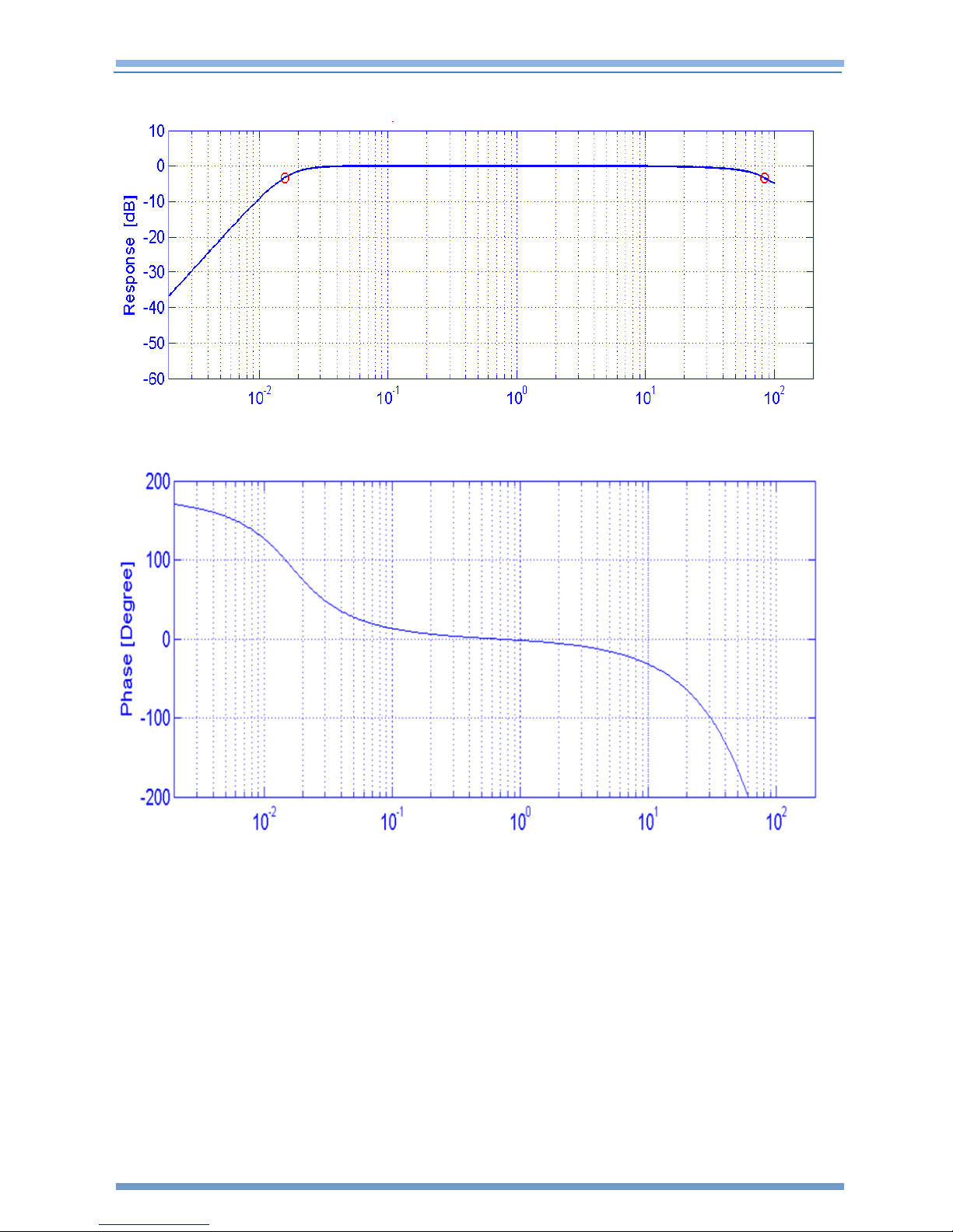
10.3 REF TEK Colt Response Characteristics
The following figures show the Magnitude-frequency and Phase-frequency
characteristic curves of the REF TEK Colt seismometers, in which the horizontal axis units
are Hz, while the vertical ones are dB and degrees respectively. The transfer Function in
the low frequency is consistent with that of traditional velocity-output seismometers
which have 120 and 60 second natural periods and a 0.707 damping coefficient.
10.3.1 Amplitude and Phase Characteristics for the 120s Colt
Figure 10-1 Amplitude frequency characteristics of the 120s REF TEK Colt
Figure 10-2 Phase frequency characteristics of the 120s REF TEK Colt
Trimble Inc. 29
Page 31
Rev A REF TEK Colt™ Broadband Seismometer User Guide 11/30/2018
117400-XX-UG
10.3.2 Amplitude and Phase Characteristics for the 60s Colt
Figure 10-3 Amplitude frequency characteristics of the 60s REF TEK Colt
Figure 10-4 Phase frequency characteristics of the 60s REF TEK Colt
Trimble Inc. 30
Page 32

Rev A REF TEK Colt™ Broadband Seismometer User Guide 11/30/2018
CAUTION
If the REF TEK Colt seismometer is going to be shipped via a commercial
shipping company, REF TEK recommends strapping the REF TEK Colt box to a
pallet. This helps to ensure that the REF TEK Colt will remain upright during
transportation.
117400-XX-UG
11 Packing and Transportation
To un-install the 151:
1. Issue a Mass Lock command from the digitizer user interface. Wait two minutes for mass
locking to complete.
2. Disconnect the cable from the top of the REF TEK Colt seismometer.
3. Before shipping the REF TEK Colt be sure to pack the seismometer in the provided shock-
absorbing shipping container.
4. Do not place the REF TEK Colt on its side or upside-down when shipping.
11.1 Warranty Statement
REF TEK instruments are warranted free from defects of manufacture for one year from
date of shipment.
For the full text covering the Product Limited Warranty, Warranty Remedies, How to
Obtain Warranty Service, Warranty Exclusions and Disclaimer, Limitation of Liability,
Official Language, Registration and any Product Extended Limited Warranty that may
apply, please see:
http://www.trimble.com/termsofsale
11.2 Warranty/Non-Warranty Service
The customer must obtain a Return Material Authorization (RMA) number from REF TEK
before returning any equipment. Do not return any REF TEK supplied equipment without
first obtaining an RMA number.
The following policy is applicable for warranty/non-warranty equipment when a
problem is encountered.
Contact Trimble by a means listed in the warranty information at the front of this
document to obtain an RMA number.
Trimble Inc. 31
Page 33

Rev A REF TEK Colt™ Broadband Seismometer User Guide 11/30/2018
117400-XX-UG
China RoHS for 120s REF TEK Colt
Trimble Inc. 32
Page 34

Rev A REF TEK Colt™ Broadband Seismometer User Guide 11/30/2018
117400-XX-UG
China RoHS for 60s REF TEK Colt
Trimble Inc. 33
 Loading...