

Page 1

e-ASK
electronic Access Security Keyless-entry
ee--FOB
FOB
RF Keyless
RF Keyless--
entry
entry
System Instructions
System Instructions
(UM02 ~ 19571-02)
Page 2

Table of Contents
Introduction .................................................................................. 1
e-FOB Operation and Features ................................................... 2
Teaching Additional Fob Transmitters ...................................... 3
Smart Led .................................................................................. 4
Dip Switch Setting Assignment .................................................. 4
DIP Switch #1: Sustained Output .............................................. 4
DIP Switch #2: Horn/Panic Mode .............................................. 4
DIP Switch #3: Automatic Lock/Unlock ..................................... 5
DIP Switch #4: Parking Light Supervision ................................. 5
DIP Switch #5: Staggered Lock/Unlock ..................................... 5
Additional System Features ........................................................ 5
Light Activation .......................................................................... 5
2nd Unlock Output ..................................................................... 5
Panic Mode ................................................................................ 5
Vehicle Alarm ............................................................................ 6
Valet Mode ................................................................................ 6
In-Vehicle Valet Activation .............................................................. 6
Remote Valet Activation ................................................................. 6
Deactivate Horn Chirp ............................................................... 6
Starter Kill Feature ..................................................................... 7
Emergency Override .................................................................. 7
Troubleshooting ........................................................................... 8
Appendix: Installation and Mounting e-FOB System ............... I
General Mounting Guidelines .................................................... I
Wiring Color Code Tables and Diagrams .................................. I
RF Receiver ................................................................................... I
Wiring Connections for Basic System Functions ....................... IV
Page 3
Introduction
This manual provides the necessary information for the installation and
use of TriMark’s e-FOB transmitter/receiver system. Basic functions of
the system include:
Locking and unlocking doors
Light activation
Panic mode
Auxiliary functions based upon configuration (see page 4)
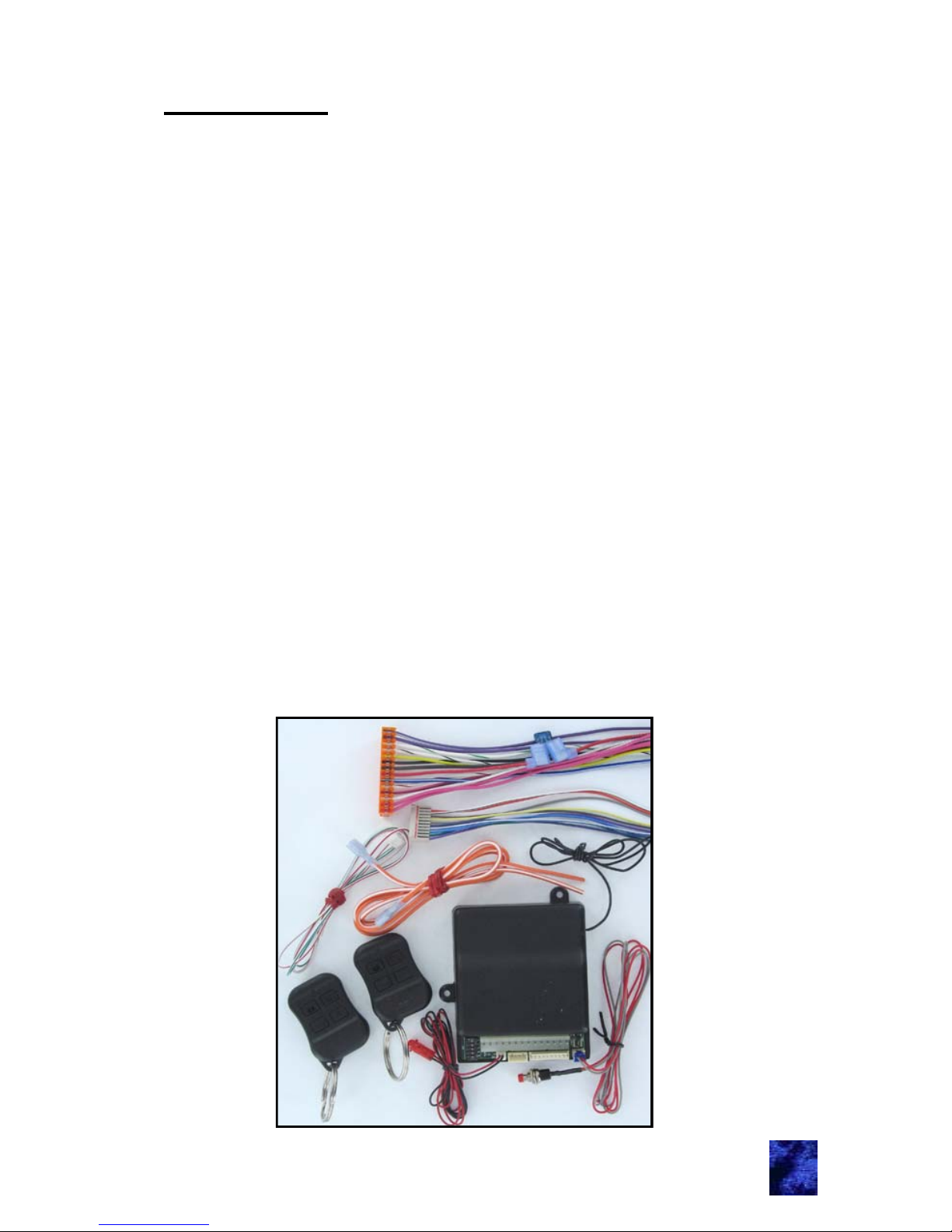
The e-FOB system includes:
Receiver
2 FOB transmitters
14-pin wire harness
10-pin wire harness
4-pin wire harness
Smart LED
Push button switch
Starter kill wires
The receiver and FOB transmitters are shipped programmed. After
making all necessary wiring connections (see appen dix page IV), the e
-FOB system will function as indicated in this manual.
1
Page 4
e-FOB Operation and Features
Notes:
While the engine is running only the entry unlock function of the
e-FOB remains activated —other functions are deactivated.
For information on changing the default configuration, see DIP
Switch Setting Assignment on page 4.
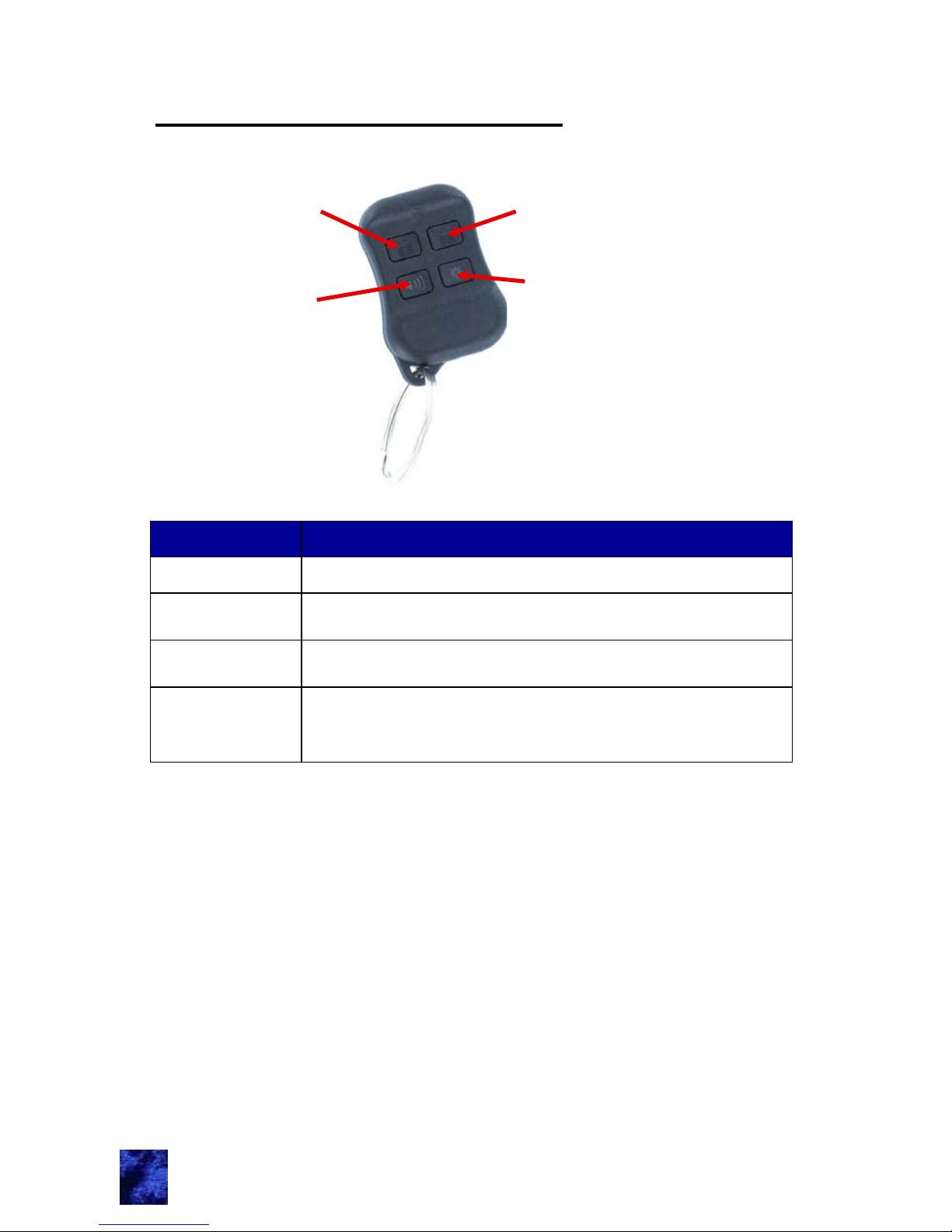
Lock button
Horn button
* button
Unlock button
2
Button Function
Lock
Locks all entry doors and arms security system.
Unlock
Unlocks entry doors and disarms security system.
Also activates the porch light.
Horn
Activates panic mode when pressed and held for 2
seconds.
* button
auxiliary
output
* button function is OEM/dealer defined. Possible
assignment include: interior/exterior lighting, awning
extension/retraction, gas cap, hood, etc.
Page 5
Teaching Additional FOB Transmitters
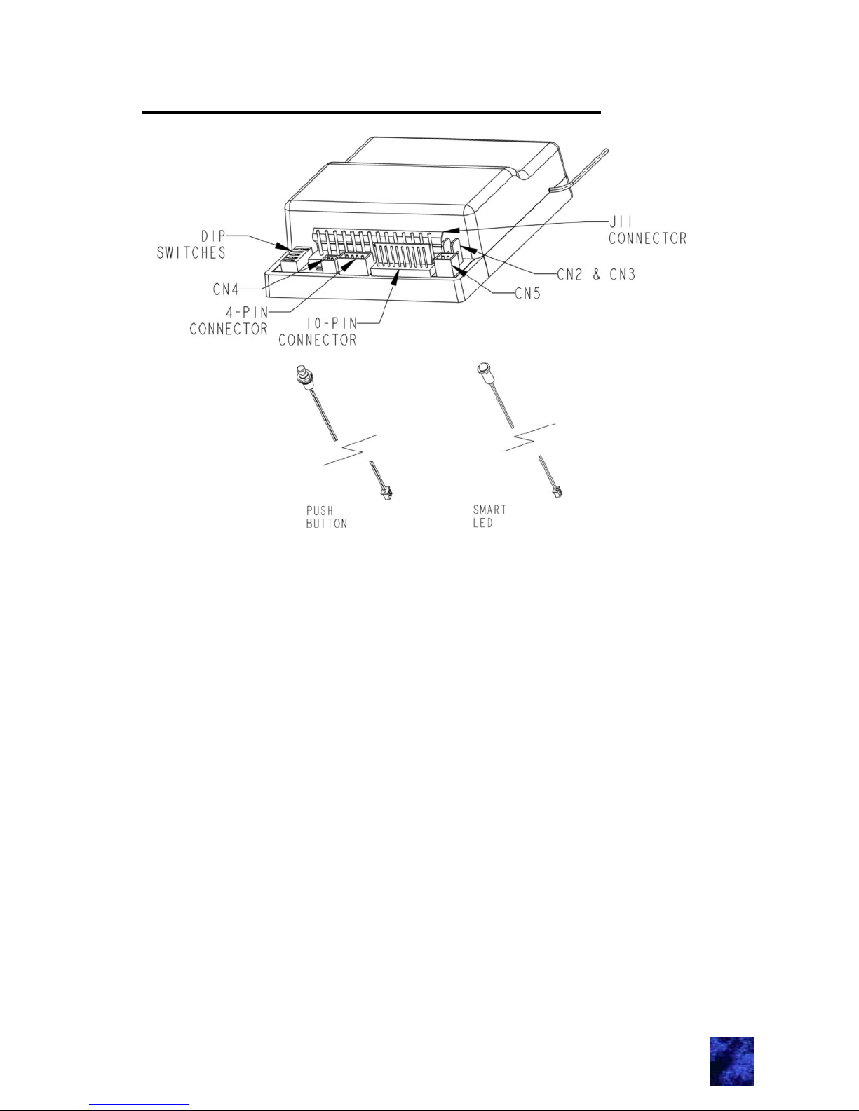
1. Plug the smart LED into CN4 and the push button into CN5.
2. Apply +12 V to the yellow wire.
3. Press and hold the push button switch until the LED assembly
turns on and then off (about 5 seconds).
4. Press the Lock button of each new FOB transmitter once (do
not hold button). Up to 4 transmitters may be programmed at
one time.
5. Disconnect the yellow wire and verify proper e-FOB transmitter
and receiver reception.
Notes:
If you place the system in learn mode and teach nothing, the
system will exit in 10 seconds.
If the 4-transmitter limit is exceeded, the system erases the
earliest trained transmitter. To erase a lost remote, teach the
remaining or new remotes a total of 4 times.
It is recommended to teach all transmitters at the same time.
This eliminates the potential to erase an earlier trained transmitter. Hold the FOBs at least 2 feet away from the controller
during training.
The memory for codes is NON-VOLATILE and will not be
erased if power is removed.
3
Page 6
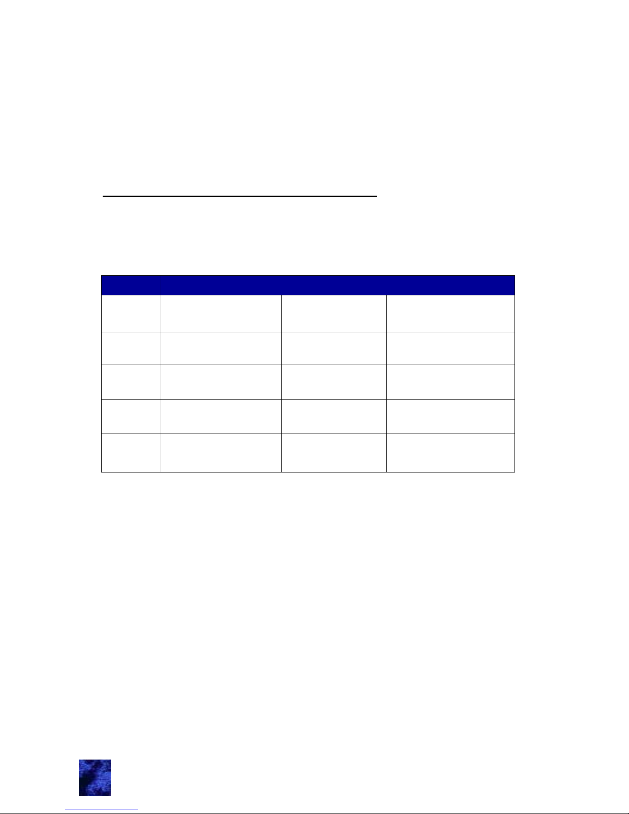
Switch
#1
Lower Buttons Sustained Output
ON = see
Switch #2
OFF = Sustained
Output
#2
Lower Left
Button Output
ON = Panic
Mode
OFF = Horn Pulse
#3
Automatic
Lock/Unlock
ON = Enabled OFF = Disabled
#4
Parking Light
Supervision
ON = Enabled OFF = Disabled
#5
Staggered
Lock/Unlock
ON = Not
staggered
OFF = Staggered
DIP Switch Settings
Smart LED:
The smart LED indicates system status:
Slow flash = Armed
Off = Disarmed
Solid on = Valet mode
Fast flash = Alarm activated since last Unlock button press
DIP Switch Setting Assignment
The DIP Switch settings control additional functions. A DIP switch
change is recognized after the Lock button is pressed. Functional
assignments are described below:
DIP Switch #1: Sustained Output
DIP switch #1 ON: output of lower left button is controlled by
DIP switch #2. lower right button provides a pulse output.
DIP switch #1 OFF: the lower buttons provide sustained
outputs. Output lasts as long as the button is pressed–up to
15 seconds. Doors must be unlocked to get a sustain ed output.
Lower left button activates pink wires. Lower right button
activates purple/white wires.
DIP Switch #2: Horn/Panic Mode
DIP switch #2 ON: the Horn button (lower left) actuates panic
mode and the horn chirps with each button press.
DIP switch #2 OFF: the Horn button (lower left) provides a
pulse output and there are no chirps with button press.
4
Page 7

DIP Switch #3: Automatic Lock/Unlock
DIP switch #3 ON: the auto-locking feature is activated. All
doors are locked 5-seconds after engine start. Doors unlock
when the engine is turned off. THIS FEATURE IS CANCELED
AUTOMATICALLY if the door is open or opened when the
engine is started. This protects against accidental locking of
keys in the vehicle.
DIP switch #3 OFF: Automatic lock/unlock feature is disabled.
DIP Switch #4: Parking Light Supervision
DIP switch #4 ON: the parking and headlights are actuated with
the dome lights. Lights flash with a lock command. Lights
remain illuminated for 30 seconds with an unlock command.
Locking the doors or starting the car deactivates the lights
immediately.
DIP switch #4 OFF: the parking and headlights flash once on a
lock command and twice on an unlock command.
DIP Switch #5: Staggered Lock/Unlock
DIP switch #5 ON: the staggered locking output occurs with
lock actuation.
DIP switch #5 OFF: the staggered lock output is staggered to
the lock actuation to decrease peak current draw.
Additional System Features
Light Activation
When the Lock button is pressed, the parking and headlights flash. With
an unlock instruction; the dome light stays illuminated for 30 seconds.
The parking and headlight actuation is controlled by DIP switch #4 .
2nd Unlock Output (optional: extra installation
required)
Press and hold the Unlock button until activation (2 seconds).
A sustained output is available through the white/brown wire on the
10-pin harness. See appendix page III for output definition.
Panic Mode
Pressing and holding the Horn button (lower left) for 2 seconds
activates panic mode. During panic mode, horn/siren is continuously
activated and headlights flash for 1 minute. Pressing the Unlock button
deactivates panic mode.
5
Page 8

Vehicle Alarm (when installed)
The alarm is armed when the doors are locked. If any outside door is
opened while the alarm is set, the horn, siren, and lights flash for 1
minute. Press the Unlock button to deactivate the alarm.
Valet Mode (requires hook-up to ignition)
Some situations, such as valet parking, or leaving the vehicle at the
dealer, require that alarm features be suspended. Placing the alarm in
“Valet Mode” suspends audible features.
In-Vehicle Valet Activation
1. Turn the ignition to the ON position with your key.
2. Press the push button (CN5) until the LED is continuously
illuminated.
Remote Valet Activation
1. Open the driver’s door (must have door ajar switches).
2. Turn the ignition to the ON position with your key.
3. Press the
* button (lower right).
Note: Repeat activation to toggle valet mode off.
In the valet mode, the doors lock and unlock normally. Other features
operate per the following list:
Arming and disarming the system will produce no chirps.
There is no alarm or starter kill feature.
The
* button and 2nd unlock auxiliary outputs do not actuate.
This provides security to storage compartments.
The panic feature actuates lights, but not horn and si ren.
Deactivate Horn Chirp
The horn chirps with button press can be toggled on/off by pressing
the Unlock button 4 times while the ignition is ON (yellow wire connected to 12 V). When the chirps are turned on, two confirmation
chirps are heard. Three confirmation chirps are heard when the chirps
are turned off.
6
Page 9

7
Starter Kill Feature
Wire the starter through CN2 and CN3. Once installed this feature
defeats the starter if the alarm is set off so that the vehicle cannot be
stolen. DO NOT BYPASS THE IGNITION OR FUEL PUMP. In case of
an emergency, the starter kill feature can be bypassed with the
emergency override.
Emergency Override
To disarm the alarm in case of FOB transmitter loss:
1. Turn the ignition to the “ON” position (connect yellow wire to
12 V). Siren and horn stops.
2. Press the push button (CN5) until the lights stop flashing and
the system disarms (2 seconds).
Page 10
This product has been manufactured with methods to ensure high
quality and to meet the high expectations of our customers. TriMark
warrants this product to be free from workmanship defects and will
remedy issues per TriMark's warranty policy.
Remote transmitter FOBs, batteries, and other equipment subject to
normal wear and deterioration may need to be replaced periodically by
dealer and/or end user and are not covered by this warranty. TriMark
will not be liable for indirect, special, incidental or consequential damages.
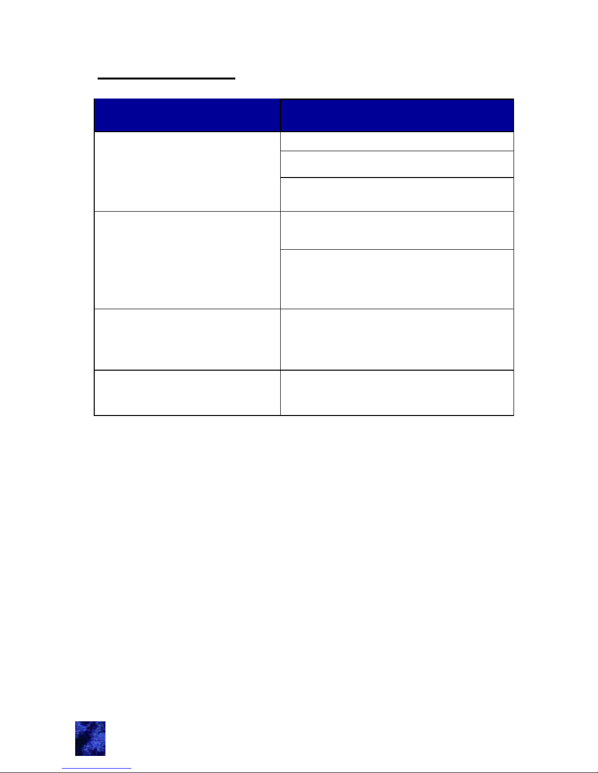
Problem Description
Possible Solution
Button press does not provide
correct operation
Verify power to the RF receiver
Replace FOB transmitter battery
Re-teach the FOB transmitter to the
receiver
No operation or intermittent
operation
Mount RF receiver away from enclosed
metal areas and fully extend antenna
Check FOB transmitter battery voltage.
Batteries need to be changed every 1-2
years depending on usage.
Horn honks, siren sounds and
lights flash when system is
hooked up or battery power is
returned.
Press Unlock button. Power was
removed while the system was locked
and armed.
One particular e-FOB function
does not work
Check wire connection of affected func-
tion at RF module and wiring harness
Troubleshooting
8
Page 11
Appendix: Installation and Mounting e-FOB
System
Contact TriMark for specific mounting details, such as drawings,
placement suggestions, mounting hardware, etc.
General Mounting Guidelines:
The RF receiver should be placed in an interior location that doe s not
shield RF signals. You may need to try multiple locations to optimize
reception. The antennae must be left fully extended and exposed.
Minimize shielding from metal enclosures.
Wiring color code tables and diagrams
The following tables and diagrams are provided to show color-coded
wire and pin assignments for the e-FOB system. Connect all wires
before plugging module into wiring harness.
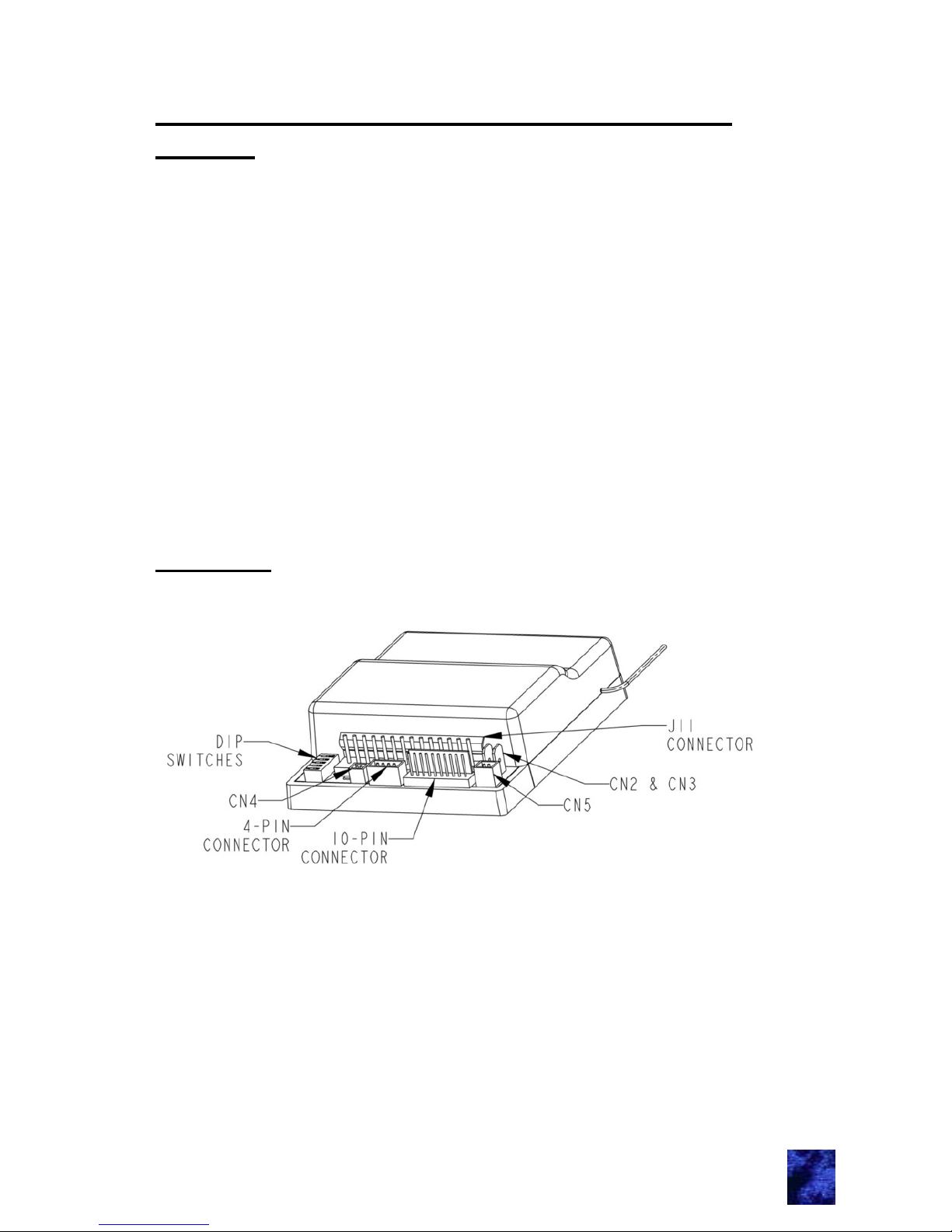
RF Receiver
I
Page 12
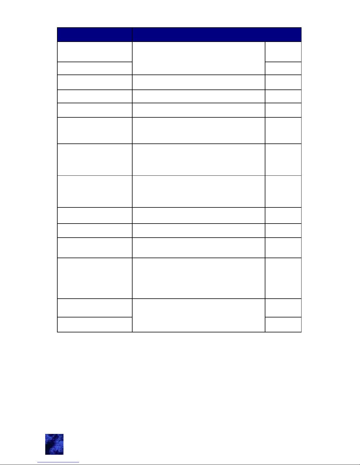
WIRE COLORS 14-PIN HARNESS
PURPLE / WHITE
AUX.
*
Button INPUT/OUTPUT.
BUILT-IN RELAY, 12A.
1
PURPLE / WHITE
A FUSE IS RECOMMENDED
2
WHITE / GREEN LOCK OUTPUT (N/C RELAY 30) 3
WHITE / BLACK LOCK INPUT (N/C RELAY 87A) 4
YELLOW CONNECT TO TRUE IGNITION 5
BLACK
CONNECT TO A CLEAN GROUND.
SOLID CONNECTION IS A MUST
6
SIREN (+) OUTPUT. UP TO 2 A
CAPACITY.
BROWN
SHORT PROTECTED
7
CONNECT TO A STRONG POWER
SOURCE. USE A FUSE
RED
AT THE CONNECTION POINT.
8
BLUE / WHITE UNLOCK INPUT (N/C RELAY 87 A) 9
WHITE / RED UNLOCK OUTPUT (N/C RELAY 30) 10
PINK / BLACK
LOCK / UNLOCK POLARITY (N/O
RELAY 87)
11
PARKING LIGHTS OUTPUT (+12V;
15A, UP TO 50A INRUSH).
WHITE
CONNECT OF PARKING LIGHTS
OF VEHICLE
12
PINK
DOME INPUT / OUTPUT; BUILT-IN
RELAY, 12A.
13
PINK
A FUSE IS RECOMMENDED.
14
II
Page 13
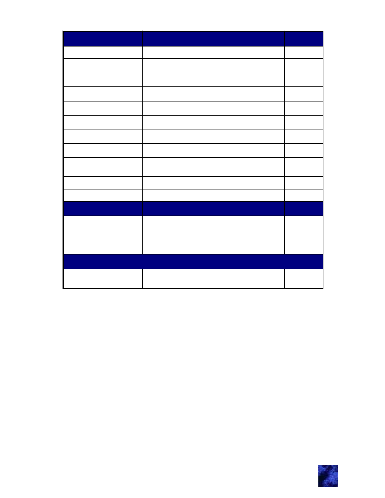
WIRE COLORS 10-PIN H ARNESS
ORANGE
ARMED OUTPUT (-) 500MA. 1
WHITE / BROWN
AUX. CHAN NEL #2 FOR LONG
UNLOCK BU TT O N PRES S
OUTPUT, (-) 500MA 2
BROWN / WHITE
HORN HONK OUTPUT , (-) 500MA 3
WHIT E / YELLOW
2ND UN LO CK (-) 500MA. 4
GRAY
LIGHT S OUTPUT. (-) 500 MA 5
PURPLE / GREEN UNASSIGNED INPUT 6
WHITE / BLUE STAGGERED LO C KING 7
BLUE
(-) SECOND ARY TRIGGER INPU T.
(TRUNK, HOOD)
8
GREEN
(-) DOOR TRIGGER INPUT
9
PURPLE
(+) DOOR TRIGGER INPUT
10
WIRE COLORS 4-PIN HARNESS
WHITE / RED
UNLOCK INPUT FROM INTERIOR
DOOR SW ITCH (GND INPUT)
2
WHITE / GREEN
LOC K INPUT FROM INTERI OR
DOOR SW ITCH (GND INPUT)
4
0.250 MALE CON NECTORS
CN2 & CN3
BUILT-IN ST AR TER KILL RELAY.
NON-POLARIZED. 40A
* DO NOT U SE A TEST LIGHT O N T H E M ODULE'S 500MA
OUTPUTS
III
Page 14
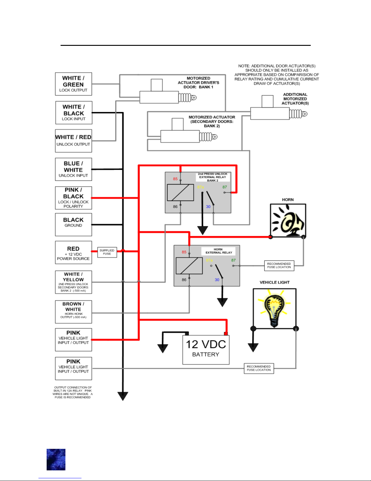
IV
Wiring Connections for Basic System Functions
Page 15

Notes
Page 16

UM02
19571-02
01/06-8
 Loading...