

Page 1

500-1300 e-ASK PKE System
(Passive Keyless Entry)
(UM31~ 500-1300)
38246 and 38847
500 Bailey Avenue
P.O. Box 350
New Hampton, Iowa 50659 U.S.A.
www.trimarkcorp.com
Page 2

In the event that you have a question regarding the Passive Keyless Entry System,
please contact Spartan RV Customer Service at the following contacts before you
contact TriMark Corporation:
Spartan Recreational Vehicle Owner Support:
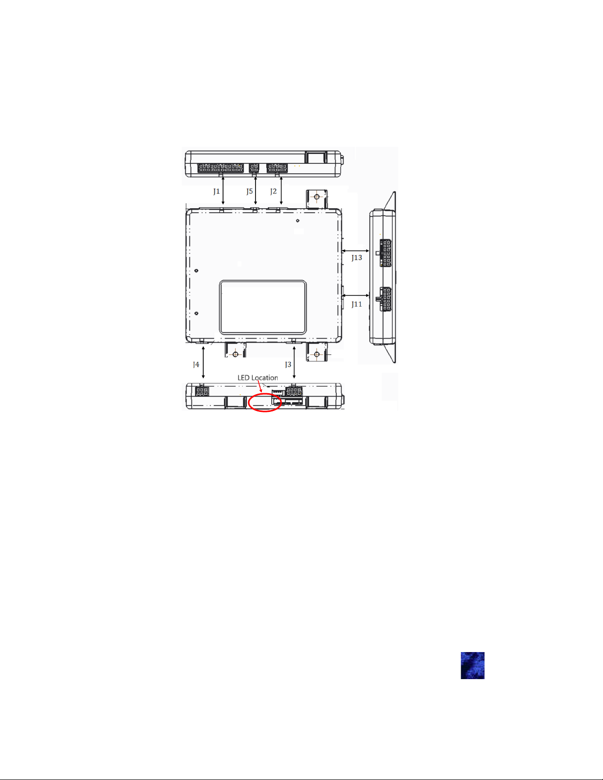
800.543.4277
(Option 1) Customer & Product Support/Chassis information
(Option 2) Owners Training Information
(Option 5) Factory Service & Repair Appointment
(Option 6) Retail, Non-warranty Parts
Table of Contents
Introduction .................................................................................. 4
General Component Overview ................................................... 4
e-Controller (38246-01 and 38847-01) ................................... 4
e-FOB (38245-01) ................................................................... 4
Lighted Grab Handle with Keypad (36444-03) ....................... 4
Antenna (36159-01) ................................................................ 5
Standard Operating Procedures—Section 1 ............................ 6
Push to Start ........................................................................... 6
Running ................................................................................... 6
Shutdown ................................................................................ 6
Locking (typical) ...................................................................... 6
Unlocking Entrance (typical) ................................................... 6
Alarm Functionality .................................................................. 6
Arming the Alarm .............................................................. 6
Feedback .......................................................................... 7
Disarming the Alarm ......................................................... 7
Cancelling the Alarm ........................................................ 7
Tripping the Alarm ............................................................ 7
Auto Locking ........................................................................... 7
Auto Lock / Unlock ............................................................ 7
e-FOB Operation and Features (38245-01)—Section 2 ............ 8
FOB Functionality .................................................................... 8
Pairing FOB ............................................................................. 9
Panic Mode ............................................................................. 9
Activating .......................................................................... 9
Deactivating ...................................................................... 9
e-ASK Fob Guidelines…………………………………………...10
Keypad Operation and Features (36444-03)—Section 3 .......... 11
Default Access Code ........................................................ 11
Default Authority Code ..................................................... 11
Standard Operation ................................................................. 11
Locking ............................................................................. 11
Unlock the Entrance Door ................................................ 11
Page 3

Unlock All Doors ................................................................ 11
Unlock Bay/Cargo Doors ................................................... 11
Teaching Keypad New Authority / Access Codes ................... 12
Programming Authority Code ............................................ 12
Programming Access Code ............................................... 12
Keypad Wiring .......................................................................... 13
Module Operation/Features (38246-01/38847-01)—Section 4 .. 14
Module Connectors and Functions .......................................... 14
Connector Locations ......................................................... 15
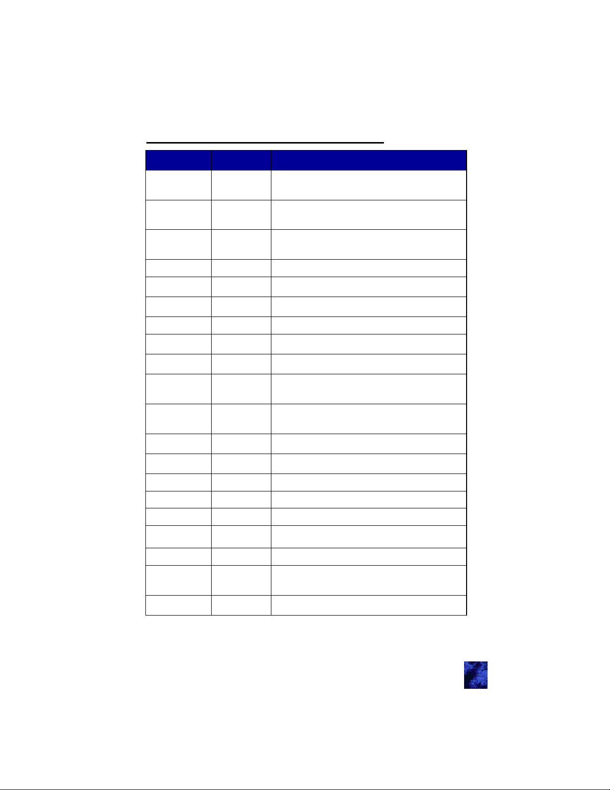
J1—Main Chassis Connector 24-Pin ................................ 16
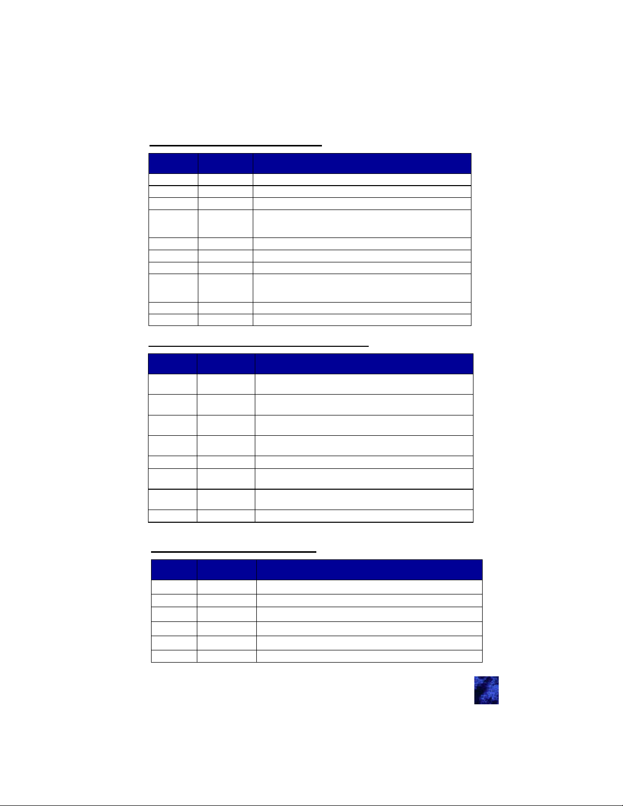
J2—Parking Break 10-Pin ................................................. 17
J3—External Relay Drivers 8-Pin ...................................... 17
J4—Relay Outputs 6-Pin ................................................... 17
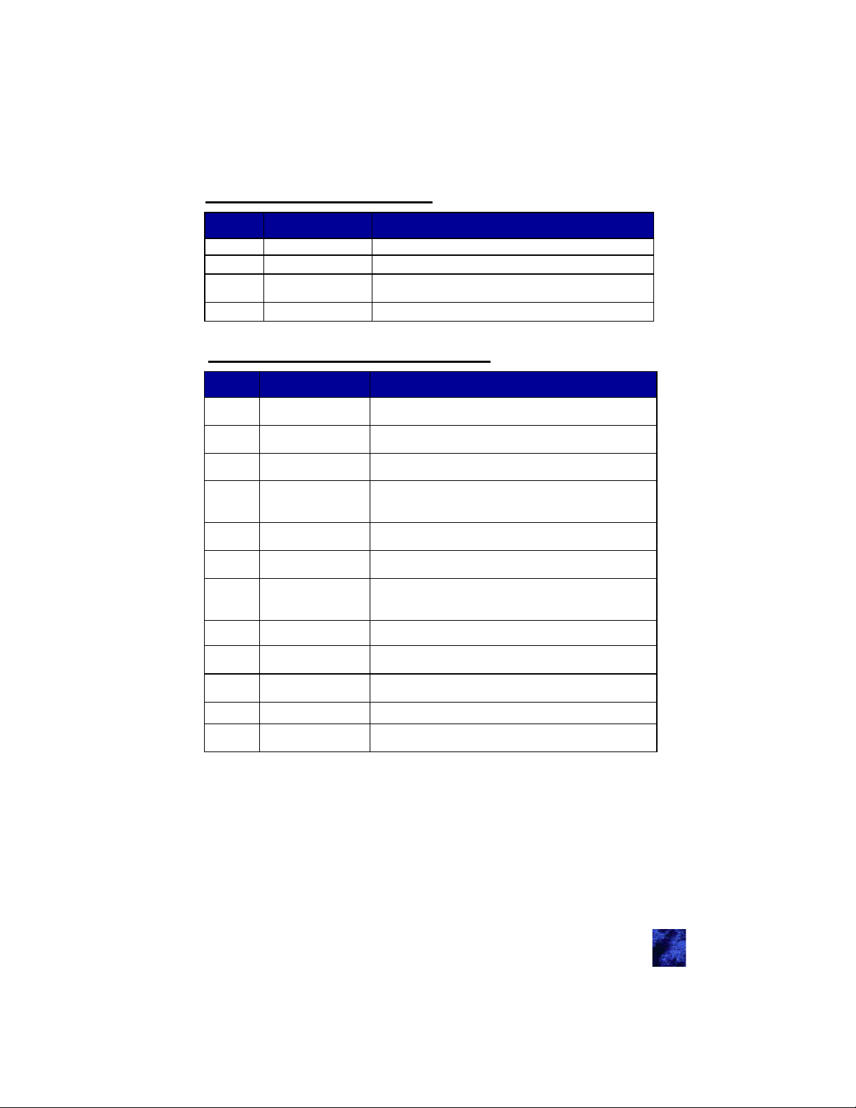
J5—Relay Outputs 4-Pin ................................................... 18
J11—Push to Start PKE 12-Pin ........................................ 18
J13—Entry Door PKE 14-Pin ............................................ 19
Dip Switch Settings .................................................................. 19
Appendix A: Wiring Diagrams
Entry Door ................................................................................ 20
Bay/Compartment Doors ......................................................... 20
PKS .......................................................................................... 21
Keypad ..................................................................................... 21
Accessories (Inputs) ................................................................ 22
Accessories (Outputs) .............................................................. 22
Appendix B: Mounting e-ASK Components .............................. 23
General Mounting Guidelines .................................................. 23
I/O Module…………………………………………………….25
Chrome Keypad………………………………………………26
Appendix C: Acronyms ................................................................ 26
Appendix D: Error Codes ............................................................ 27
Appendix E: Troubleshooting ..................................................... 28
Appendix F: CAN Requirements ................................................. 31
Appendix G: Warranty ................................................................. 32
TriMark makes every attempt to assure that information contained in
the User Manual is correct and accurate; however, changes in design,
dimension and specifications may occur at any time and without notice.
Please verify the revision level of this manual (back page) by referring
to TriMark’s website under Product Code 500-1300.
Note: Product photos and illustrations may vary from your specific part
numbers.
Page 4
Introduction
This manual provides the necessary information for the proper
installation and use of TriMark’s e-ASK system. The e-ASK comes with
the following components:
e-FOB: Keyless entry RF FOB transmitter with Passive keyless
LF PKS (Passive Keyless Start) ability
e-ASK I/O Module: The input/output processor with low
frequency (LF) and RF transceiver capabilities
Antennas: LF interior antennas for FOB section
Handle with Touchpad: A five button chrome handle. It allows
for locking and unlocking functions via a CAN network
This new generation of TriMark’s e-ASK not only maintains its previous
advantages for controlling door and accessory control, it also adds
value to the Original Equipment Manufacturer (OEM) and customer by
incorporating remote keyless entry, immobilization and keyless start
into a single package.
The FOBs have typical lock/unlock buttons that can be used up to 50
meters depending on architecture and location. For security reason, RF
signals are encrypted using randomly generated numbers. This is what
allows the system to start by pressing a button. The system uses the
LF/RF messaging to ensure an authorized FOB is within range inside
the vehicle. A combination of LF challenges and RF responses delivers
low power consumption for long battery life.
General Component Overview:
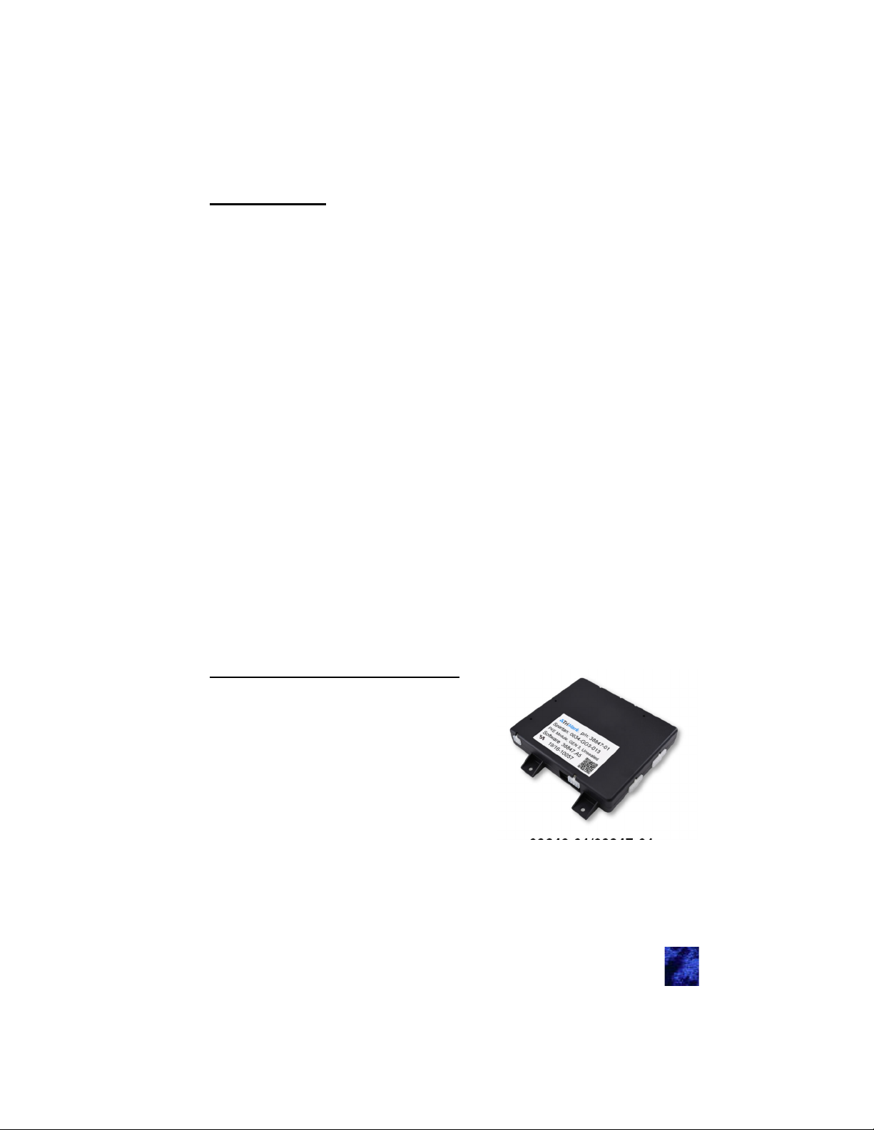
e-CONTROLLER (38246-01/38847-01)
Enables distributed functionality,
such as multiple door control and
ignition immobilization, via vehicle
multiplex communication
CAN network functionality with error
handling
Fault displaying LEDs
LF transceiver (FCC/IC compliant)
RF transceiver (FCC/IC compliant)
Programming port
Selectable visual/audible controls
38246-01/38847-01
4
Page 5
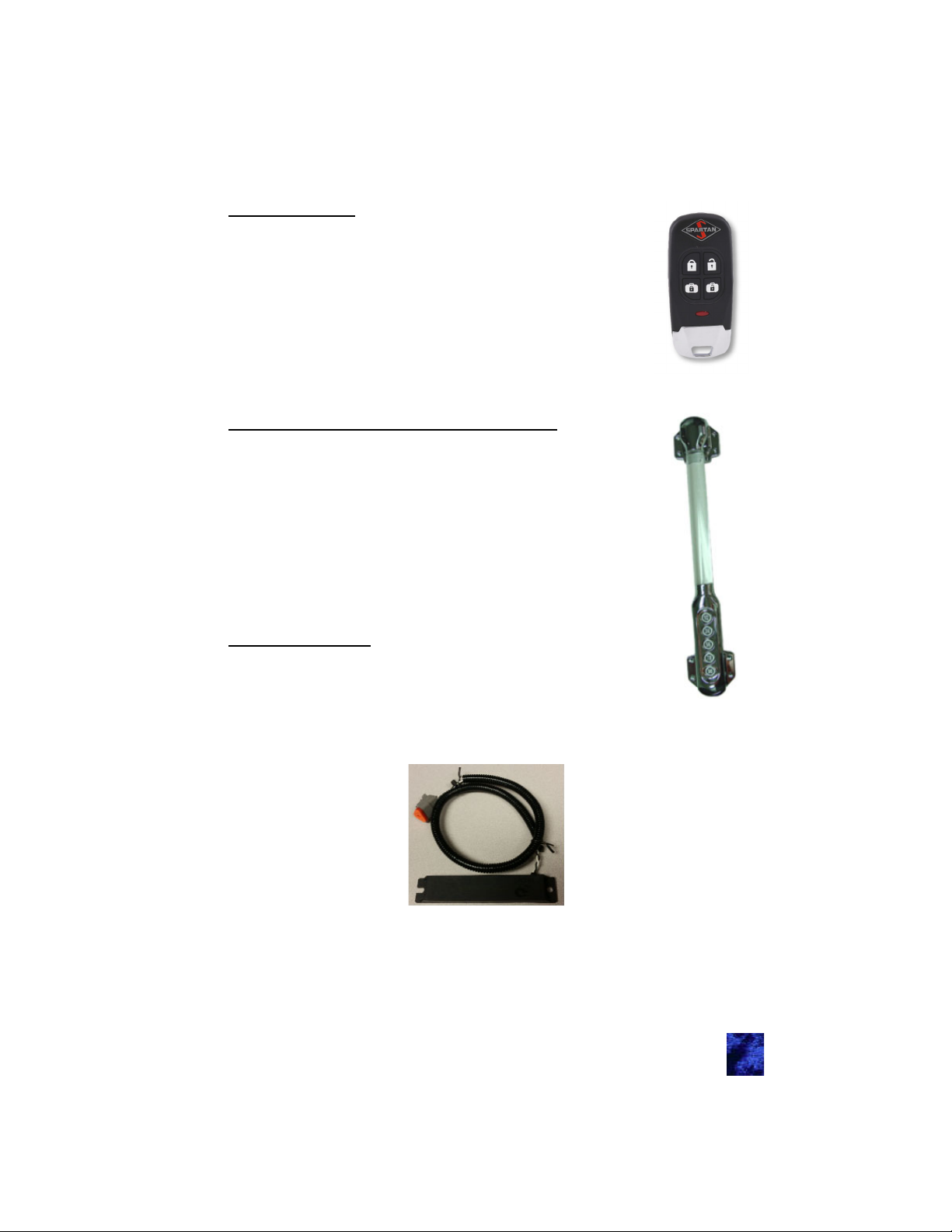
e-FOB (38245-01)
Stylish 4-button PKE FOB
LF transceiver that can reach 1 meter though open
air and is FCC/IC/EU compliant
RF transceiver that can reach 100 meters though
open air and is FCC/IC/EU compliant
Control lock, unlock, lighting, alarm system, and
panic operations
High security using random number generators and
proprietary decryption algorithm between the FOB
and controller to prevent attacks/hacking
Lighted Grab Handle with Keypad (36444-03)
Entry assist handle incorporated TriMark’s e-ASK
keypad into a stylish combo for RV coaches, motor
homes and travel trailers
Lighted rod and lighted assist keypad for a more
enjoyable low visibility experience
Button presses with tactile, visual, and audio feedback
CAN network with error handling and communicates
with the TriMark e-Controller
Fault display both audio and visual
Water and dust resilient to outdoor environments
Antenna (36159-01)
Location identifying internal antenna for push to start
functionality
Potted construction ensures environmental protection
and durability performance—can be used in exterior or
interior locations
38245-01
36444-03
36159-01
5
Page 6

Standard Operating Procedures — Section 1
Push to Start
Pressing the engine start button will begin the process of detecting a
FOB in range (J11P2 active). Our system will look in the area of the
driver. If the FOB is in range it will respond with a single blink. If the
FOB is authorized. Our system will tell the motor that it may start.
Running
Once running, the FOB is not required to keep the vehicle running.
Note: You can drive away without your FOB in the vehicle. You will not
be able to start the vehicle again without the FOB.
Shutdown
With your vehicle in park, a short press of the start/stop button will turn
off the vehicle.
Locking (typical)
Press and hold the Button 1 button on the keypad or press the lock
function on the FOB.
Unlocking Entrance (typical)
Type in the five digit code followed by the 1 button or press the unlock
function on the FOB.
Note: Programming new codes into your keypad can be found in
section Keypad Operation and Features (36444-03) - Section 3
under Teaching Keypad New Authority / Access Codes.
Alarm Functionality
Arming the Alarm:
Performing a “lock all” with the touchpad or the key FOB will attempt to
set the alarm.
The word “attempt” is used above because several conditions can block
the alarm from being armed:
Parking brake not set (in gear)
Pressing the button to start the vehicle
Any security inputs are in the active state
Any door ajar input are in the active state
6
Page 7
Feedback:
If you activate the alarm from keypad, the system will send a
single pulse to the headlights.
If you activate the alarm from the FOB, the system will send a
single pulse to the headlights and horn/siren.
If you fail to activate the alarm the siren will sound 3 times.
Disarming the Alarm:
The alarm system will immediately be disarmed if one of the following
things occurs:
You start the engine
Any unlock signal
The vehicle is put into gear
Cancelling the Alarm:
Any of these conditions will cancel an active alarm:
The vehicle is put into gear
The engine is started
An unlock command of any door/compartment
The alarm timer expires
Tripping the Alarm:
After arming the alarm, if the security input (J1P13) or any of the door
ajar inputs are tripped, the alarm will activate. When active, the siren
will go off and the headlights will flash for one minute.
Auto Locking
Parking Brake Description
The parking brake is active and the vehicle
Engaged Active
Disengaged Float
cannot move. The vehicle is considered “not in
use”.
The vehicle will move if no other brakes are
applied. The vehicle is considered “in use”.
This is usually caused by putting the vehicle
into gear.
Auto Lock / Unlock
The parking brake is monitored to utilize this auto locking feature:
Whenever the vehicle parking brake activates, a timer is started.
Seven seconds later a lock all sequence is done.
Whenever the vehicle parking brake activates, the entrance door
is unlocked.
7
Page 8
e-FOB Operation and Features (38245) —
Section 2
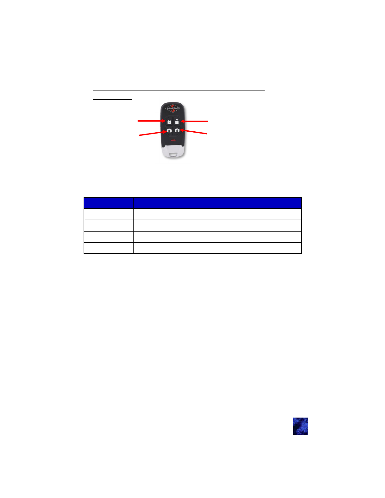
Lock All
Lock Cargo
38245-01
Unlock Entry
Unlock Cargo
FOB Functionality
Button Function
Lock All Locks all doors
Unlock Entry Unlocks entry doors
Lock Cargo
Unlock Cargo
Pressing a button on the FOB should cause the LED to flash multiple
times. The LED will also flash anytime it is located by an antenna. This
happens when you start your vehicle and the FOB search near the
drivers seat is initiated.
The FOB is powered by a standard 2032 3V battery.
Note: Typical use has 2 years without replacing the batteries. May be
subject to variation from OEM as the time the FOBs were created is not
the day the coach was sold.
Locks the cargo doors in the order of section A, B, C, D
Unlocks the cargo doors in the order of section A, B, C, D
8
Page 9

Pairing FOB
You will need to have access to the module to pair FOBs. To
understand pin names and functions please reference Module
Operation and Features (38246-01/38847-01) — Section 4.
There may be a push button attached to J13P2, if it is not supplied,
short J13P2 (learn pin) to J11P1 (12Volt pin) when it says “push
button”.
Note: Programming new FOBs will unlearn any programmed FOBs
previously stored. You may learn up to 50 FOBs. Make sure you have
all the FOBs that you wish to program before starting this process.
1. Press the push button 3 times within 5 seconds (more than 3 is
acceptable)
a. The system will send a pulse to lock and unlock the entry
door
b. Two LEDs (red and green) located near the dip switches will
remain on as long as the controller is in learn mode
2. Press and release a button (any button) on each FOB
a. The system will send a pulse to lock and unlock the entry
door
3. Wait 10 seconds
a. Entry door unlocks and you exit FOB learn mode
Panic Mode
Activating
The Panic Mode sequence is activated by pressing and holding for 2
seconds the panic button on the FOB. During Panic Mode, siren and
headlight outputs are used to draw attention to the vehicle. Panic mode
cannot be used if the parking brake is not active (vehicle in gear).
Deactivating
Panic time of 60 seconds expires
Unlock command from the FOB
Unlock from the keypad
Vehicle engine turns over
Parking brake inactive (vehicle in gear)
9
Page 10

The e-ASK fob is designed to use commonly available CR2032
batteries. Estimated end customer normal use should have an expected
life of 2 years for the fob battery. Variances across commercial battery
manufacturers and operating environment conditions will result in
deviations from the expected battery life. The following guidelines
should be followed to optimize fob battery life and system performance.
The e-ASK fobs are designed to operate in a low power or “sleep”
mode. The fobs electronics will “wake up” upon detection of a button
press or LF signal from the control module. The fob will return to “sleep”
mode once the event that woke it up is completed.
When a fob is in close proximity, 2-3 inches, from other vehicle control
units, cell phones or inductive cell phone charger pads, electrical
signals from these devices can prevent the fob from returning to “sleep”
mode and can reduce battery life. Additionally, when in close proximity
to these other electrical devices, their emitted electrical signals can
saturate the fobs internal receiving antennas and prevent the fob from
receiving proper LF signals.
It is recommended for optimal fob performance and battery life that a
distance of at least 5-6 inches minimum be maintained between fobs
and other such mentioned electronic devices.
Due to the chemical process inherent in batteries, the performance of
the e-ASK Fob will be degraded at extreme temperatures. Operating
temperature ranges will vary across batteries from different
manufactures. For commercially available CR2032 batteries the typical
operating temperatures ranges from –0C to +60C.
At cold temperature, the batteries chemical process is slowed down and
can result in reduce Fob range performance or an inoperative fob.
When the battery is returned to warmer temperatures, normal
performance will return. Extreme cold temperatures, below –20C, can
cause a battery to freeze and fail due to expansion of internal plastic
components. Simply replacing the battery will allow the fob to function
normally.
At extreme hot temperatures, the batteries chemical process is
accelerated. This will result in a reduced life expectance of the battery.
Normal Fob range performance can be expected at higher temperatures
as long as manufacture limits are not exceeded.
10
Page 11
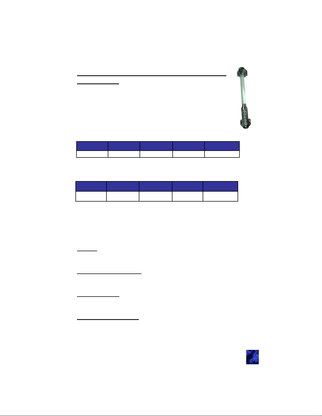
Keypad Operation and Features (36444-03)
— Section 3
The keypad can store one authority code and four access codes.
The authority code is used to create access codes
The access codes are used to unlock the vehicle
This allows for the owner to have one code and make separate
codes for someone else.
Default access code:
Digit 1 Digit 2 Digit 3 Digit 4 Digit 5
Button 1 Button 2 Button 3 Button 4 Button 4
Default authority code:
Digit 1 Digit 2 Digit 3 Digit 4 Digit 5
36444-03
Button 4
Note: If it has been changed and you don’t know what it is, please go
to the Teaching Keypad New Authority / Access Codes section.
Button 4 Button 4 Button 4 Button 4
Standard Operation
Note: The dome light will turn on for 30 seconds upon any button press.
Locking
Press and hold the1 button for 2 seconds will lock entrance doors and
bay/compartment doors.
Unlock the Entrance Door
Put in a valid 5-digit access code (double beep from keypad) followed
by Button 1.
Unlock All Doors
Put in a valid 5-digit access code (double beep from keypad) followed
by Button 2.
Unlock Bay/Cargo Doors
Put in a valid 5-digit access code (double beep from keypad) followed
by Button 3.
11
Page 12
Teaching Keypad New Authority / Access Codes
All codes are exactly 5 digits. You may reuse numbers. Changing the
authority code erases all access codes. It is highly recommended that
you change your authority code from the default code.
Programming Authority Code:
Note: There is a video of how to do this (it will not play on Apple
tablets). http://www.trimarkcorp.com/en/media/Videos/eask/All%
20Keypads/index.html
Preparation:
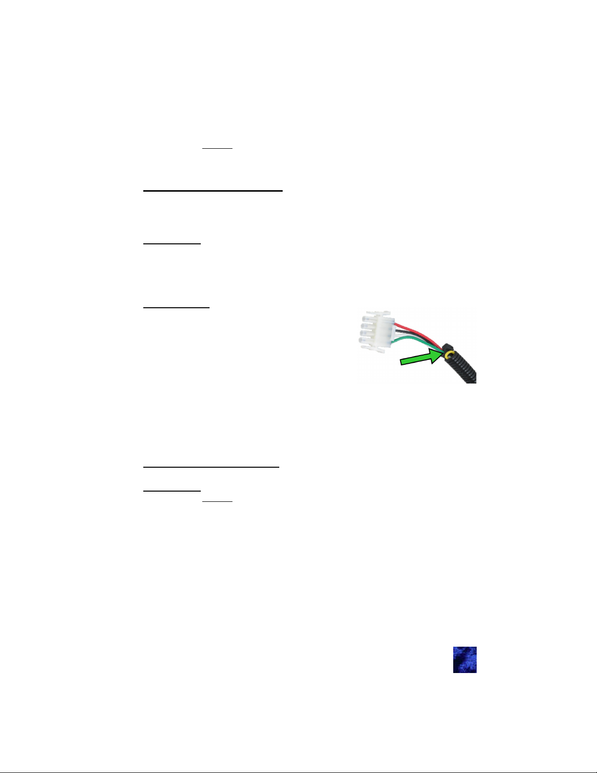
The keypad is plugged into the coaches wiring harness with a four pin
connector. You will need to unscrew the keypad and pull it away from
the coach to expose this connector. The yellow wire that is tucked into
the sheathing is the wire that initiates programming mode.
Programming:
1. With the keypad still plugged in, short the
yellow wire to the black wire (GND)
momentarily. This will cause the keypad
to beep for one second.
2. Enter the desired 5-digit code twice (after
programming the system will immediately
exit learn mode).
3. Test the code by unlocking the entrance
door
Note: We recommend changing the access code when RV is acquired.
The system automatically stores an access code the same as your
authority code in location Button 1.
Programming Access Codes:
Preparation:
All codes are exactly 5 digits. You may reuse numbers. Have a number
chosen.
Programming:
1. Press and hold Button 3 for 5 seconds. The keypad will beep
and begin flashing when it is held long enough
2. Enter the 5 digit authority code
a. If you enter the correct code you will hear a constant beep
and please continue to step 3
b. If you enter the incorrect code you will hear a 1 second beep.
Please double check the authority code
12
Page 13
3. Choose a location to store this code
a. Button 1 = Location 1
b. Button 2 = Location 2
c. Button 3 = Location 3
d. Button 4 = Location 4
4. Enter the desired 5-digit code in twice.
5. Test by unlocking the entry door.
Note: You may store up to 4 codes in the system. You may write over
a location by simply programming an access code over that location.
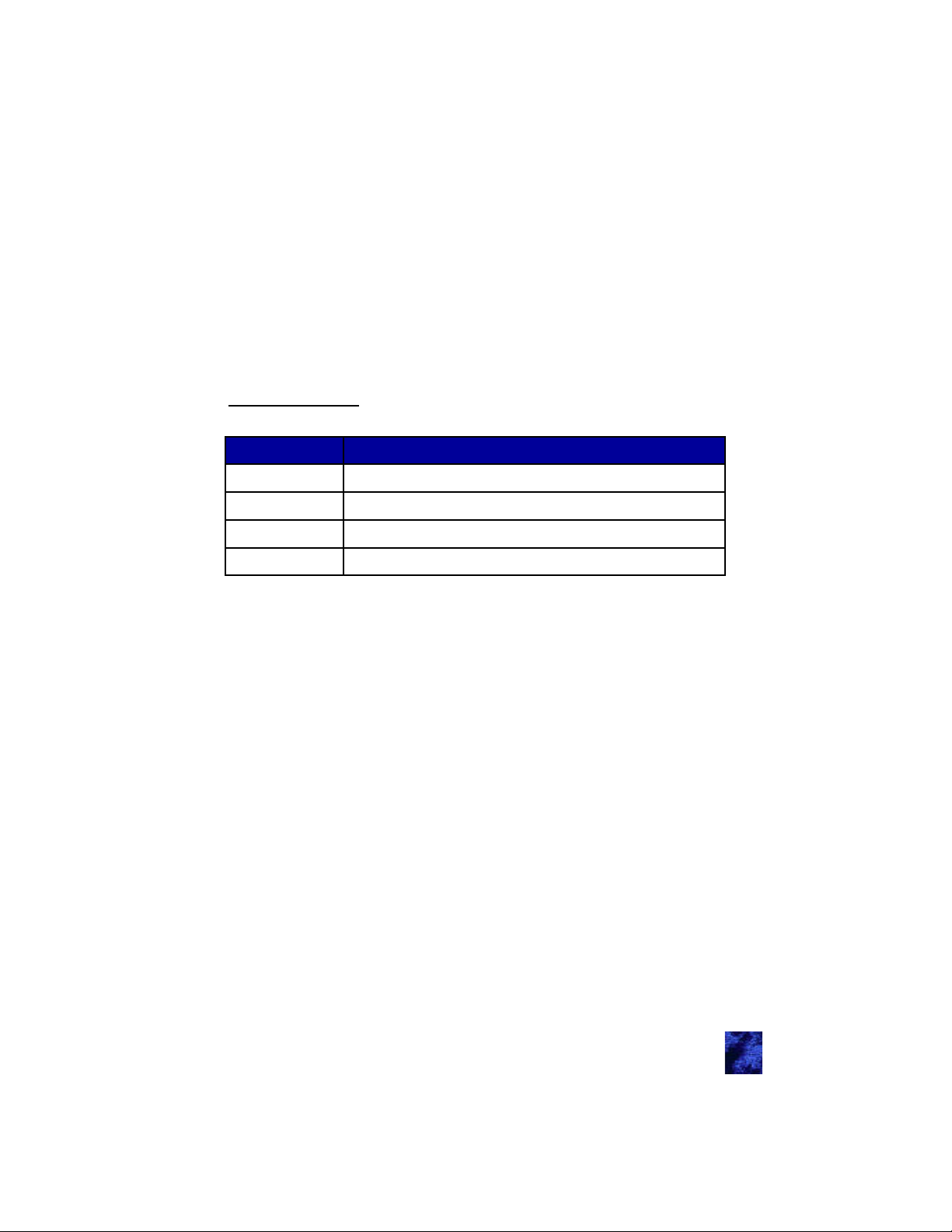
Keypad Wiring
Wire Color Wire Function
Red 12 Volt battery power
Black Ground
White
Green
CAN High (communication line)
CAN Low (communication line)
12
Page 14
Module Operation and Features
(38246-01/38847-01) — Section 4
Module Connectors and Functions
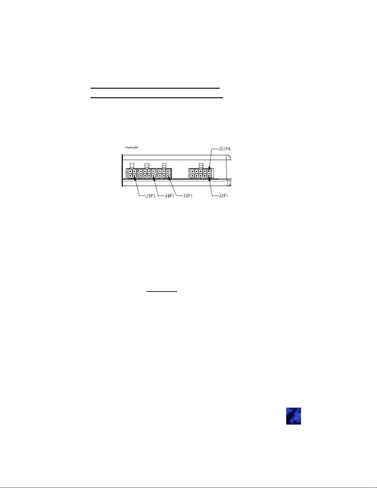
If you look at the TriMark IO module with the label pointed up, the
numbering system is bottom right to top left (opposite of how you read).
(see diagram below)
For all inputs:
(-) indicates that the inputs normally floats (no predetermined
voltage to input) unless a ground signal is placed to activate pin.
(+) indicates that the inputs normally floats (no predetermined
voltage to input) unless a 12V signal is placed to activate pin.
(+/-) indicates that the inputs normally floats (no predetermined
voltage to input) the voltage is the opposite of J2P7 to activate
(selectable).
For all outputs:
(-) upon activation a 500mA ground path will be activated.
(Relay 20A) a momentary path that is normally ground will be
vehicle power (lock unlock doors, extra).
(Relay 30A) Bank D has multiple pins to allow higher currents
through these connectors. The four pins to allow this higher
current are J1P5, J1P6, J1P17, and J1P18 described on the next
page.
Note: Most fuses are based on wire gauges. Fuses should be gauged
accordingly.
For all Signals:
Follow CAN/J1939 protocol (see acronyms)
For all Antennas:
An AC signal (for communications)
14
Page 15
Connector Locations
15
Page 16
J1—Main Chassis Connector 24-Pin
Pin Input/Output Function
J1P1 Input (-)
J1P2 Input (-)
J1P3 Input (-)
J1P4 & J1P16 Input Vehicle Ground
J1P5 & J1P17 (Relay 30A)
J1P6 & J1P18 (Relay 30A)
J1P7 & J1P19 Input Vehicle Battery—Powers relays
J1P8 (Relay 20A)
J1P9 Input (-)
J1P10 Input (-)
J1P11 Input (-)
J1P12 Input (-)
J1P13 Input (-)
J1P14 (Unused Pin)
Bank C-D Unlock
Ground this input to unlock compartment Banks C
and D.
Bank A-B Unlock
Ground this input to unlock compartment Banks A and
B.
Compartment Door Ajar
Ground this input to indicate any of the compartment
doors are ajar.
Bank D Lock
30A max relay output
Bank D Unlock
30A max relay output
Entry Door Unlock
20A max relay output.
Unlock Entry
Ground this input to unlock the entry door.
Unlock All
Ground this input to unlock the entry door and all
compartment doors in Banks A-D.
Lock All
Ground this input to lock the entry door and all com-
partment doors in Banks A-D.
Lock Entry
Ground this input to lock the entry door.
Security
Ground this input to indicate a break in and activate.
J1P15 (Unused Pin)
J1P20 (Unused Pin)
J1P21 (Relay 20A)
Entry Door Lock
20A max relay output.
J1P22 (Unused Pin)
Entry Door Ajar
J1P23 Input (-)
J1P24 (Relay 20A)
Ground this input to indicate any of the entry doors
are ajar.
Dome Light
20A max relay output.
Note: Grounding J1P1 and J1P2 together will unlock banks A-D in order.
16
Page 17
J2—Parking Break 10-Pin
Pin
J2P1 Input Vehicle Battery—Powers relays
J2P2 (Unused Pin)
J2P3 (Unused Pin)
J2P4 Input (+-)
J2P5 (Unused Pin)
J2P6 Vehicle Ground
J2P7 Input (+-) Acts as the electrical return path of J2P4 and J2P8
J2P8 Input (+-)
J2P9 (Unused Pin)
J2P10 Vehicle Ground
Input/
Output
Function
Parking Brake Sensor
Active with the opposite voltage of J2P7. J2P7 is the return
path (electrically) to activate input
Lock Compartments Switch
Active with the opposite voltage of J2P7. J2P7 is the return
path (electrically to activate input
J3—External Relay Drivers 8-Pin
Pin
J3P1 Output
J3P2 Output (-)
J3P3 Output (-)
J3P4 Output (-)
J3P5 Output (-) (Not Assigned)
J3P6 Output (-)
J3P7 Output (-)
J3P8 (Unused Pin)
Input/
Output
Function
12V Regulated Power
12V reference voltage for external relays.
Horn
For external relay
Headlight
For external relay
Doorbell
For external relay
Door Ajar
For external relay
Siren
For external relay
J4—Relay Outputs 6-Pin
Pin
J4P1 (Relay 20A) Bank C Lock
J4P2 (Relay 20A) Bank B Lock
J4P3 (Relay 20A) Bank A Unlock
J4P4 (Relay 20A) Bank B Unlock
J4P5 (Relay 20A) Bank C Unlock
J4P6 (Relay 20A) Bank A Lock
Input/
Output
Function
17
Page 18
J5—Relay Outputs 4-Pin
Pin Input/Output Function
J5P1 Output Keypad Ground
J5P2 (Unused Pin)
J5P3 Output
Keypad Power
12V regulated output
J5P4 (Unused Pin)
J11—Push to Start PKE 12-Pin
Pin Input/Output Function
J11P1 Input
J11P2 Input (+)
J11P3 Output (Relay 20) (Not Assigned)
J11P4 Output (-)
J11P5 Input (+)
J11P6 Antenna
J11P7 Output (Relay 20)
J11P8 Output (Relay 20) (Not Assigned)
J11P9 Signals
J11P10 Signals
J11P11 Input Vehicle Ground
J11P12 Antenna
Vehicle Battery
Powers all ICs and relays on J11 connector.
AUTH_REQ
Input to request PKS system to locate FOB.
AUTH_RESP
While AUTH_REQ is active, the I/O module will activate
this out if an authorized FOB is in range.
Door Handle—Proximity Sense Input to request PKE
system to locate FOB
LF Antenna 1—Interior Area 1
Used to sense FOBs inside the vehicle cab.
Door Lights
Activates to Power to turn on the vehicle exterior Door
Lights.
CAN Low
Connection to vehicle’s CAN bus.
CAN High
Connection to vehicle’s CAN bus.
LF Antenna 1—Return path
Used to sense FOBs inside the vehicle cab.
18
Page 19
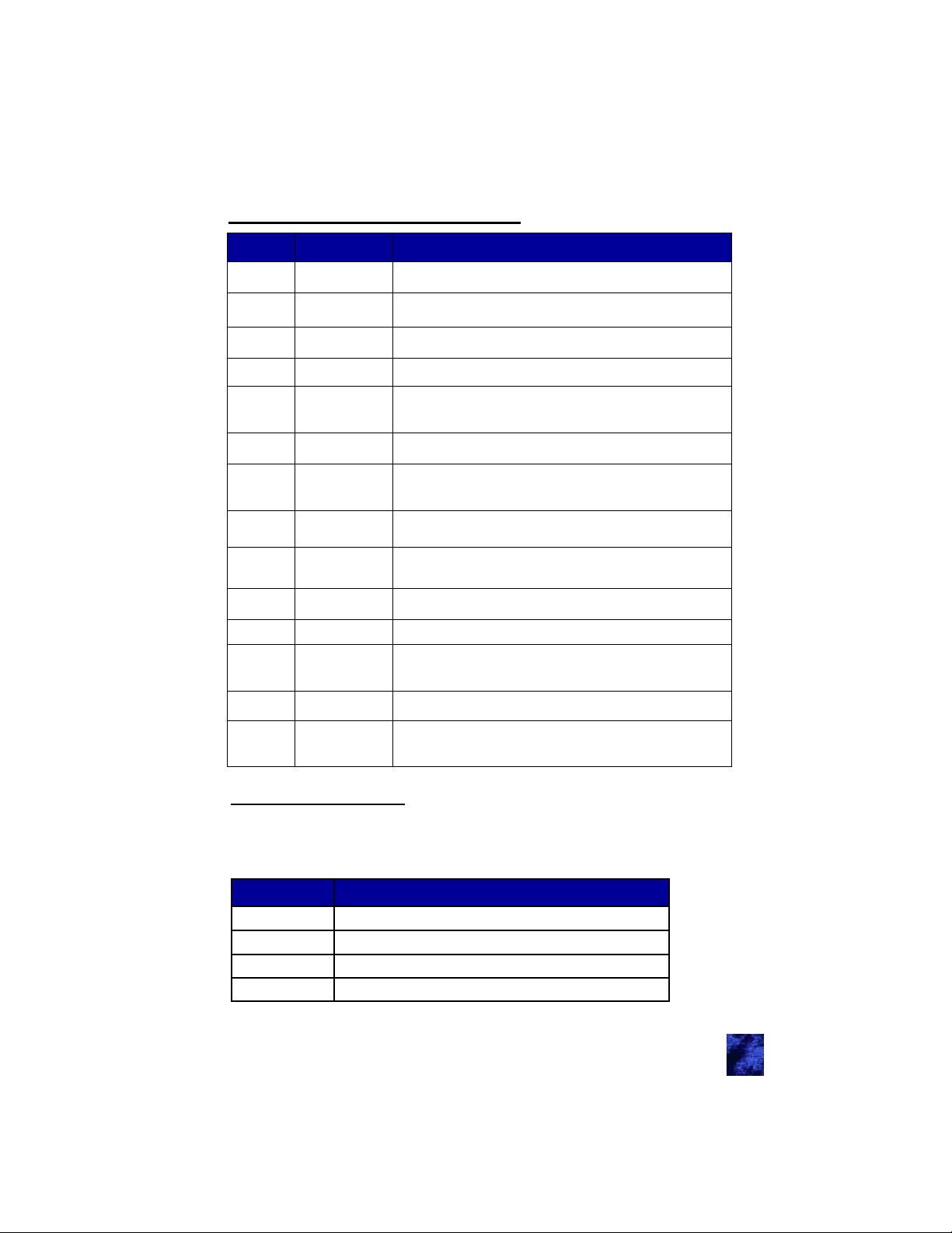
J13—Entry Door PKE 14-Pin
Pin Input/Output Function
J13P1 (Not Assigned)
J13P2 Input (+)
J13P3 Output (-) (Not Assigned)
J13P4 Output (-) (Not Assigned)
J13P5 Antenna
J13P6 (Unused Pin)
J13P7 (Unused Pin)
FOB Learn Mode Request
Using this input to program FOBs.
LF Antenna 2—Exterior
Used to sense FOBs exterior to the vehicle cab near the
door handle.
J13P8 Output
J13P9 Input (+)
J13P10 Input Vehicle Ground
J13P11 (Not Assigned)
J13P12 Antenna
J13P13 Input Vehicle Ground
J13P14 Antenna
Door Handle Power
12V regulated power output for the door handle.
Door Ajar
Activating this input indicates at lease one door is ajar.
LF Antenna 2—Return path
Used to sense FOBs exterior to the vehicle cab near the
door handle.
RF Antenna
Attached to a wire at least 40” long for HF communication
Dip Switch Settings
The dip switches are there to enable/disable any visual/audio functions
this controller provides. Dip switches are located next to the J3
connector
Dip Switch Function
1 Unassigned
2 Siren (J3P7)
3 Headlights (3P3)
4 Horn (J3P2)
19
Page 20
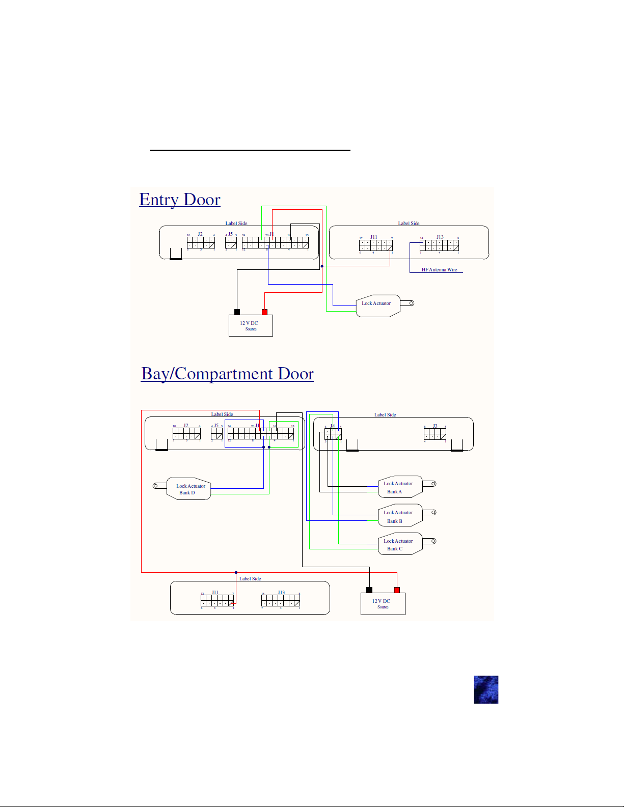
Appendix A: Wiring Diagrams
20
Page 21
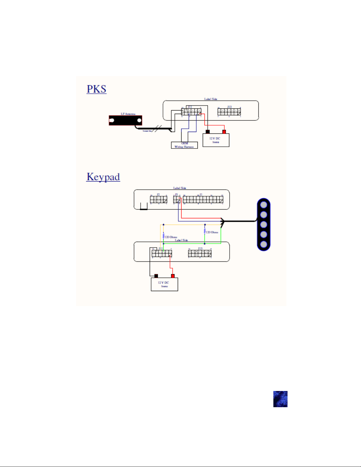
21
Page 22
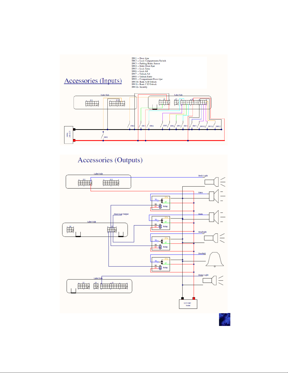
22
Page 23

Appendix B: Mounting e-ASK Components
This system uses low-voltage circuitry and wireless communication.
To protect these components and to ensure the device operates as
expected, these application notes must be followed.
General Mounting Guidelines:
Typical RF antenna implementation consists of a single wire from the
control module. To ensure optimal reception the RF antenna wire
should be designed to the following specifications:
Wire Length: 107.5cm +/- 1cm
Wire Type: 22AWG, Braided tined
The tip of the antenna wire should also be covered with heat shrink
tube or plastic dip to prevent the possibility of bare wire contacting
vehicle chassis locations and grounding the antenna.
The RF antenna should be placed in an interior location that does not
shield RF signals. You may need to try multiple locations to optimize
reception. The antennae must be left fully extended and exposed.
Minimize shielding from metal enclosures or chassis body panels that
could act as a ground plane.
Looping the antenna, wrapping the antenna around a metallic object,
or grouping the antenna wire in with another wire harness may affect
the functional operating range of the remote key fobs. Routing of the
antenna wire near wires with large or rapid voltage fluctuations may
also have a detrimental effect on the controller. If the antenna wire
must be routed with other wires due to vehicle design constraints,
care should be taken in harness manufacturing to ensure the antenna
wire is routed on the outside of the wire harness bundle and away
from wires that have large or rapid voltage fluctuations.
The vehicle control module contains several internal mechanical
relays. If a relay is exposed to excessive G-force loads (greater than
30 G), it could toggle unexpectedly. It is important that the control
module be mounted in a suitable location to prevent exposure to
excessive G-force loads. Examples of poor mounting locations include
on or inside doors, near chassis suspension features, or near internalcombustion engines.
23
Page 24

TriMark e-ASK LF antennas are designed to be spaced off any
metallic surfaces. Mounting the antenna to a metal surface without the
space will result in the antenna’s transmitted signal to be absorbed
and Fob detection range will be reduced to a few inches. The
suggested distance from the metal surface is 3/8” or farther.
24
Page 25
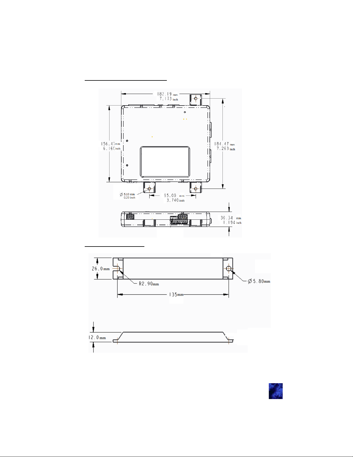
IO module: 38246-01/38847-01
LF Antenna: 36159-01
25
Page 26
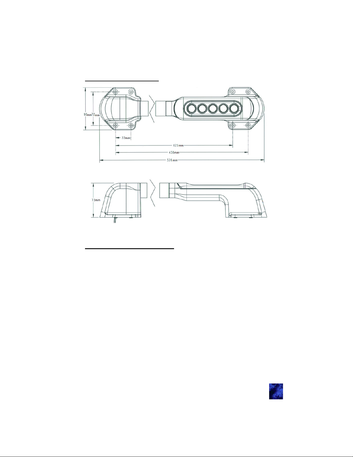
Chrome Keypad: 36444-03
Appendix C: Acronyms
PKE: Passive Keyless Entry. The ability to unlock the door by placing
your hand in the door handle.
RKE: Remote Keyless Entry. The ability to lock/unlock the door by a
button press on the FOB
PKS: Passive Keyless Start: The ability to start/stop the vehicle with
a button press.
FOB: The remote that allows PKE/RKE/PKS to work properly.
RF/LF: Radio Frequency/Low Frequency. The frequency band that the
module and FOB communicate on.
CAN: Controller Area Network: This is a computer BUS system that is
highly accurate low data rate system that has been adapted by
most vehicles throughout the word.
J1939: This is the protocols over how to talk over a CAN network. This
sets priorities, authentications, and configurations of the
messages.
OEM: Original equipment manufacturer.
26
Page 27
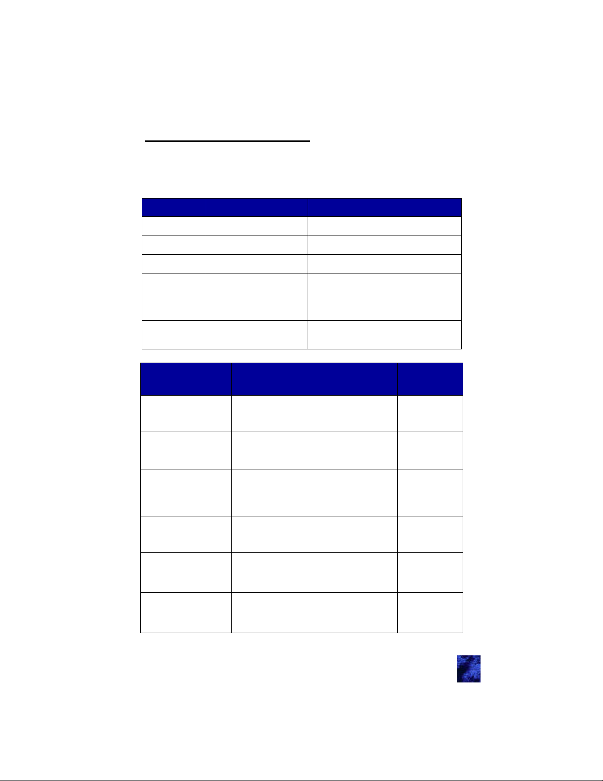
Appendix D: Error Codes
There is a red and green LED located to the left of the programming
port. This is visually shown in the Module Connectors and Functions
under Connector Locations. The purpose of these LEDs is to indicate
the mode the system is in.
Green LED Red LED Software Mode / Current State
On On Internal programming occurring
On Off Normal full-power operation
Off Off No power
Run-time error detected. The value of
Off
Blink X times, then wait
1.5 seconds and repeat
“S” indicates the exact error that is
detected. The table below give more
information of each possible error
Fast blink
(5 time/second)
Fault Exact Error
CAN error (continue to
Appendix D: Trouble-
shooting
CAN error (continue to
Appendix D: Trouble-
shooting
LF receiver not responding (continue to
Appendix D: Trouble-
shooting
Door locks relays not
responding
CAN error (continue to
Appendix D: Trouble-
shooting
Damaged IC chips
(continue to Appendix
D: Troubleshooting
Fast blink
(5 time/second)
No CAN Traffic for 2 seconds while vehi-
cle is in gear
A CAN line is above 5VDC 2
LF Module Communication Error 3
I/O Expander Module Communication
Error
CAN Bus Data Erratic No CAN Traffic for
5 seconds
EEPROM Read/Write Error 6
Pairing FOBs mode
Errors
Blinks “X”
1
4
5
27
Page 28
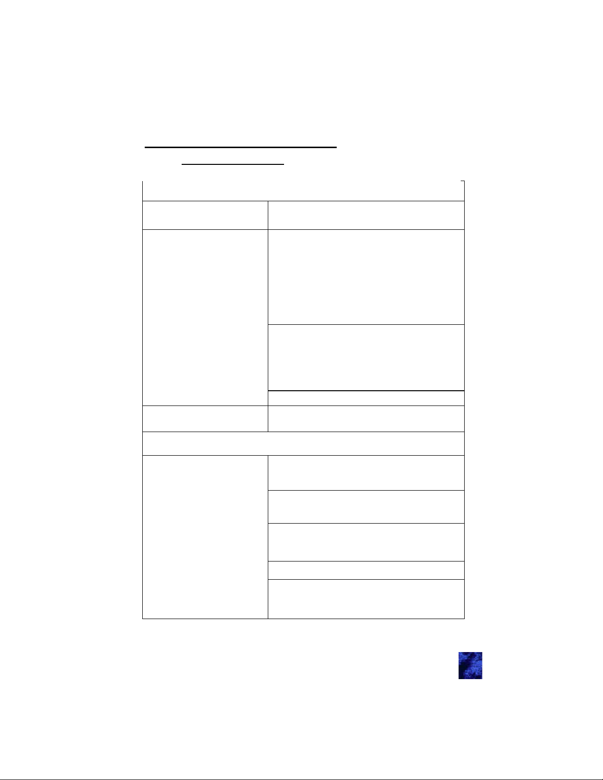
Appendix E: Troubleshooting
Note: A complete power cycle requires that power is removed for 2
minutes!!!
Keypad is not functioning
No audible beep when
button is pressed
It beeps one long and two
shorter beeps
I put the 5 digit code in and
it doesn’t do a double beep
Pressing the Start button won’t start the vehicle
The button blinks three
times and nothing happens
Check for power
This is a CAN error and is usually due to
wiring harness issues. Please refer to
Appendix E: CAN requirements for harness
requirements.
The keypad doesn’t think it can talk to
anyone so it is nonfunctional until the
CAN issue is resolved. This includes
programming.
Make sure module has power
There are two LEDs one red and one
green. They are located inside the
mofule. One or the other should be
blinking or on. Connector Locations
section identified the location
Replace keypad
Reprogram access code
Make sure that pressing a button on the
FOB makes the LED blink
If no replace battery
Make sure the FOB LED blinks when you
press the start button and the FOB is in
range of the antenna (steering column)
Replace battery
The LED can blink and still not have the
power to send messages
Check fuses
Check the J13P14 wire. This is an antenna
and should be laid out as described in
Appendix A: Mounting e-ASK Components.
28
Page 29
Re-sync FOBs
Check power to J11 connector
Power Cycle
Check wiring harness for the LF atenna
attached to the J11 connector (these antennas
are b-directional)
Check wiring harness J11P4 and J11P2
(communication lines between the module and
vehicle computer) for conductivity
The button blinks five
times and nothing
happens
Pressing Lock or
Unlock will not operate
a specific door by
keypad or FOB
Lock and unlock will
not unlock any doors
by keypad or FOB
Check wiring harness J11P4 and J11P2
(communication lines between the module and
vehicle computer) for conductivity
Will not lock or unlock
Clean door contacts
Power is supplied to the actuator through
spring loaded metal conductors. Make sure
they are clean.
Check actuator (replace if needed)
These actuators are 12V bi-directional.
You shoud be able to activate them with a
12VDC one way to lock and the other to
unlock.
Check voltage at door contact
We send a .5 second pulse one direction
for lock, and the other for unlock. Most
voltmeters average over .75 seconds so
you may not see the 12VDC, but you
should see your voltmeter move.
Check Harness for conductivity
If you can hear the internal relays click, check
power to either the J1 connector or the J2
connector
The power to the relays are separate from
the power to the electronics.
The J11 connector powers the electronics
and the relay coils (the clicking sound).
J1 and J2 connectors are on the same
power plane. Powering one, powers them
both. For relays to give power one or both
will need power given to it.
29
Page 30

Nothing is happening
Check the fuses
Check system LEDs. For locations of LED
please go to section
Connector Locations Check power to the
J11 connector
Lock and unlock will
not work the FOB only
The FOB works but it is intermittent or has bad range
Sometimes the FOB
works and sometimes
it doesn’t
One FOB is not
syncing
The light and horn stop
working
Change FOB battery
Resync FOB(s)
Arrange the antenna as discussed in General
Mounting Guidelines
Power cycle system
Make sure to sync all FOBs together
Check dip switches
Check external relay banks
Check wiring conductivity
30
Page 31
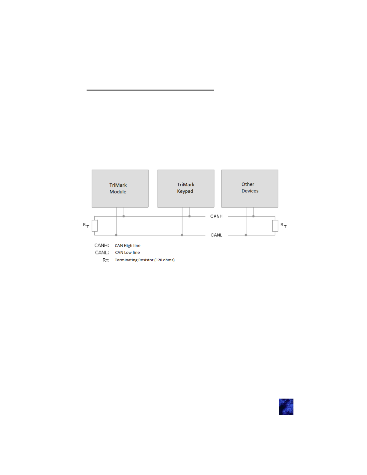
Appendix F: CAN Requirements
There must be at least two CAN systems on the CANH and
CANL.
There needs to be a resistors at each end of the CAN network
(total of two).
With everything unplugged, the harness must be 60 ohms be-
tween CANH and CANL.
Highly recommended that CANH and CANL wires are twisted
together
31
Page 32

Warranty — Section 6
TriMark warrants that the products manufactured and sold shall be in
accordance with specifications and free from defects in materials and
workmanship for a period up to 18 (eighteen) months following the date
of delivery to TriMark’s customer or 12 (twelve) months from the
original O.E.M. sale (in-service) date. Where TriMark does not have
design control with regard to customer supplied products, materials or
specifications, the warranty is limited to non-conforming product.
This warranty is expressly limited to persons who purchase TriMark’s
products for the purpose of resale or use in the ordinary course of the
buyer’s business. This warranty does not cover any product that if
TriMark Corporation determines (in its sole discretion) that a product's
failure or malfunction is due to one or more of the following conditions,
such failure or malfunction is EXCLUDED from the warranty provided
hereunder: (1) used in a manner that exceeds published engineering
specifications; (2) has been abused, misused, disassembled/opened,
altered/modified, or improperly installed; (3) is used in an application
not previously approved by TriMark; (4) is used in a manner
inconsistent with any instructions and good industry practices
regarding its use; (5) wear or deterioration due to environmental
conditions; (6) unusual mechanical, physical or electrical stress or (7)
is destroyed/damaged by fire, lightning or an act of God. In addition to
the above, TriMark will not warrant any electrical/electronic products
with (8) burned or broken traces on the printed circuit board; (9) burned
or damaged components; (10) dirt or water residue on the printed
circuit board or inside the case; (11) motor failure due to thermal
failure; (12) or dead batteries.
This warranty is exclusive, and TriMark makes no other warranty of
any kind whatsoever, expressed or implied, with respect to the
products manufactured and sold by it, whether as to merchantability,
fitness for a particular purpose or any other matter. Without prior
written authorization from the Board of Directors, no agent, employee
or representative of TriMark has any authority to bind TriMark to any
affirmation, representation or warranty concerning TriMark products or
parts, except as stated herein.
If any product supplied by TriMark is found to be defective by TriMark
in its sole discretion, TriMark reserves the right to replace, rework,
repair, or give credit for defective product. Upon confirmation of the
defective condition of the subject part either with return of subject part
and/or proper documentation, TriMark will replace such defective
product exclusive of any labor, shipping, transportation or delivery cost
associated with the replacement. TriMark will not be responsible for the
cost of removal of a defective product. This remedy shall be the
exclusive remedy available for any defects in the products
32
Page 33

manufactured and sold by TriMark or for damages resulting from any
other cause whatsoever, including without limitation, TriMark's
negligence. The purpose of this exclusive remedy shall be to provide
the buyer with replacement of products or parts sold by TriMark found
to be defective in materials or workmanship or negligently
manufactured. This exclusive remedy shall not be deemed to have
failed of its essential purpose so long as TriMark is willing and able to
replace said defective products or parts in the prescribed manner.
WITHOUT LIMITING THE FOREGOING, TRIMARK SHALL NOT BE
LIABLE FOR CONSEQUENTIAL OR INDIRECT DAMAGES,
ECONOMIC LOSSES, LOSS OF USE, LOST PROFITS, DOWN TIME
OR DAMAGES DUE TO DELAY, WHETHER BY REASON OF
BREACH OF WARRANTY, BREACH OF CONTRACT, NEGLIGENCE,
STRICT LIABILITY OR OTHERWISE.
This product has been manufactured with methods to ensure high
quality and to meet the high expectations of our customers. TriMark
warrants this product to be free from workmanship defects and will
remedy issues per TriMark's warranty policy.
Remote transmitter FOBs, batteries, and other equipment subject to
normal wear and deterioration may need to be replaced periodically by
dealer and/or end user and are not covered by this warranty. TriMark
will not be liable for indirect, special, incidental or consequential
damages.
This system complies with part 15 of the FCC Rules. Operation is
subject to the following two conditions:
(1) This device may not cause harmful interference and
(2) This device must accept any interference received including
interference that may cause undesired operation.
Note: The manufacturer is not responsible for any radio or television
interference caused by unauthorized modifications to this equipment.
Such modifications could void the user’s authority to operate the
equipment.
Note: No part of this publication may be copied, modified, revised,
reproduced, distributed, reused, transmitted to a third party, or
translated in any language without the prior written permission of
TriMark Corporation.
33
Page 34

Notes
34
Page 35

Notes
35
Page 36

In the event that you have a question regarding the Passive Keyless Entry System, please contact Spartan RV Customer Service at
the following contacts before you contact TriMark Corporation:
Spartan Recreational Vehicle Owner Support:
800.543.4277
(Option 1) Customer & Product Support/Chassis information
(Option 2) Owners Training Information
(Option 5) Factory Service & Repair Appointment
(Option 6) Retail, Non-warranty Parts
UM31
8/19-4
 Loading...