

Page 1

Artisan Technology Group is your source for quality
new and certied-used/pre-owned equipment
• FAST SHIPPING AND
DELIVERY
• TENS OF THOUSANDS OF
IN-STOCK ITEMS
• EQUIPMENT DEMOS
• HUNDREDS OF
MANUFACTURERS
SUPPORTED
• LEASING/MONTHLY
RENTALS
• ITAR CERTIFIED
SECURE ASSET SOLUTIONS
SERVICE CENTER REPAIRS
Experienced engineers and technicians on staff
at our full-service, in-house repair center
Instra
Remotely inspect equipment before purchasing with
our interactive website at www.instraview.com
Contact us: (888) 88-SOURCE | [email protected] | www.artisantg.com
SM
REMOTE INSPECTION
View
WE BUY USED EQUIPMENT
Sell your excess, underutilized, and idle used equipment
We also offer credit for buy-backs and trade-ins
www.artisantg.com/WeBuyEquipment
LOOKING FOR MORE INFORMATION?
Visit us on the web at www.artisantg.com for more
information on price quotations, drivers, technical
specications, manuals, and documentation
Page 2

IR104-V4
User Guide
Opto-isolated Industrial I/O Relay Module
Tri-M Technologies Inc.
Toll Free: 1.800.665.5600
Direct: +1.604.945.9565
Email: [email protected]
Web: www.tri-m.com
Artisan Technology Group - Quality Instrumentation ... Guaranteed | (888) 88-SOURCE | www.artisantg.com
Page 3
Page 2
IR104-V4 User Guide
Rev A
Preface
Important Notes
About Tri-M Technologies Inc.
Tri-M Technologies Inc. specializes in embedded computing for rugged environments. Tri-M’s innovative solutions are
the premiere choice for off-highway vehicles, industrial controls, robotics, military equipment, aerospace technologies,
undersea and advanced security products. We offer a wide range of DC-to-DC converters, CPU boards, hardened
enclosures, I/O modules, wireless communication devices, and customized systems. With over 28 years of industry
experience, Tri-M is your embedded systems specialist.
Who this Guide is For
This user guide is intended for integrators of embedded system applications. It contains detailed information on hardware
and software requirements to interconnect to other embedded devices. Carefully read this user guide before you begin
installation. The user should be familiar with practicing safe techniques while making supply or pin connections.
User Guide Revision History
Revision Date Description
A 12 Jan 2012 Rebranded
Trademarks
Trademarks, registered trademarks, and product names are the property of their respective owners and are used herein
for identication purposes only.
Contact Information
Tri-M Technologies Inc.
101–1530 Kingsway Avenue
Port Coquitlam, BC V3C 6N6 Canada
Telephone Toll free North America: 1.800.665.5600
Direct: +1.604.945.9565
Website
www.tri-m.com
To submit a request for technical support, please complete the online form at
www.tri-m.com/support/contact.html
To request an RMA, please complete the online form at
www.tri-m.com/support/rma/index.html.
Technical Support
Business hours: M–F, 8:30am to 5pm PST
Warranty
For warranty information, see "Tri-M Technologies Inc. (Limited Warranty)" on page 17.
Artisan Technology Group - Quality Instrumentation ... Guaranteed | (888) 88-SOURCE | www.artisantg.com
Page 4

Page 3
IR104-V4 User Guide
Rev A
Important Safety Instructions
Conventions Used in this Guide
Note
This note contains important or useful information in the use or installation of the product.
CAUTION
The caution provides information to prevent potential equipment damage or shock hazard.
Electrostatic Discharge (ESD) Precautions
To avoid electrostatic discharge or transient voltage damage to the board, observe the following procedures:
• Before touching the board, discharge your body and any tools you use from electricity.
• Ensure that the board or the unit you want to install the board on is de-engergized before installing.
• Do not touch any devices or components on the board.
CAUTION: Shock Hazard
As soon as the board is connected to a working power supply, touching the board may result in electrical shock, even if the
board has not been switched on yet.
Artisan Technology Group - Quality Instrumentation ... Guaranteed | (888) 88-SOURCE | www.artisantg.com
Page 5

Page 4
IR104-V4 User Guide
Rev A
Contents
Important Notes .....................................................................................................................................2
Contact Information
Important Safety Instructions
Conventions Used in this Guide
Electrostatic Discharge (ESD) Precautions
1 Introduction ..........................................................................................................................................6
Overview
Key Specications
Options
Specications
Dimensions and Connector Locations
................................................................................................................................................6
..................................................................................................................................................6
........................................................................................................................................7
Electrical Specications
Environmental Specications
Mechanical Specications
MTBF
Certications
...............................................................................................................................................7
....................................................................................................................................7
.........................................................................................................................2
.................................................................................................................3
......................................................................................................3
.....................................................................................3
.................................................................................................................................6
...................................................................................................................7
...........................................................................................................7
...............................................................................................................7
...................................................................................................8
2 Connectors ...........................................................................................................................................9
Connector Overview
Terminal Plugs (CN1 & CN2)
Opto-isolated Inputs (CN4)
PC/104 8-bit Bus (J1)
PC/104 16-bit Bus (J2)
3 Conguration
I/O Map
..................................................................................................................................................13
Relay Output Control (ROC)
ROC Grouping .........................................................................................................................................13
ROC I/O Map ...........................................................................................................................................13
Digital Input Reading (DIR) ..............................................................................................................13
DIR Grouping ...........................................................................................................................................13
DIR I/O Map .............................................................................................................................................14
..............................................................................................................................9
...........................................................................................................9
..............................................................................................................10
......................................................................................................................11
....................................................................................................................12
.......................................................................................................................................13
............................................................................................................13
Artisan Technology Group - Quality Instrumentation ... Guaranteed | (888) 88-SOURCE | www.artisantg.com
Page 6
Page 5
IR104-V4 User Guide
Rev A
Input Change Flags (ICF) ................................................................................................................14
Contents
ICF Grouping ...........................................................................................................................................14
ICF I/O Map..............................................................................................................................................14
Interrupts Control Register (ICR) .....................................................................................................15
ICR Grouping ...........................................................................................................................................15
ICR I/O Map .............................................................................................................................................15
Base Addresses .....................................................................................................................................16
Warranty and Product Information
Tri-M Technologies Inc. (Limited Warranty)
Disclaimer
Appendix
....................................................................................................................................................18
........................................................................................................................................17
Frequently Asked Questions (FAQ)
..........................................................................................................17
.....................................................................................17
.......................................................................................................18
Artisan Technology Group - Quality Instrumentation ... Guaranteed | (888) 88-SOURCE | www.artisantg.com
Page 7
Page 6
IR104-V4 User Guide
Rev A
1 Introduction
Overview
Tri-M’s IR104 PC/104 relay module is designed for controlling low and high current loads operating in rugged
industrial environments. The IR104 features 20 opto-isolated digital inputs and 20 relay outputs, ideal for
industrial control applications. The bidirectional inputs are isolated up to 3000V and can handle input voltages
from 3V to 24V AC or DC. The 2×20 SPST (normally open) relays have dual 20-position detachable screw
terminal blocks designed for 14 to 24 AWG wiring. The contacts are UL Certied and rated for 5A, 250VAC and
30VDC, allowing the IR104 to directly control small motors or solenoids.
In order to take full advantage of the IR104, up to 4 modules can be stacked. This maximizes IR104’s
functionality to congure IRQs and input change ags. Tri-M also offers custom designs, such as 12V or Solid
State relays for lower current draw and less interference. For more information, please visit http://www.tri-m.
com/support/proservices.html.
Key Specications
• 20 Opto-isolated bi-directional inputs with 3000V protection
• 20 SPST Output Relays with 20,000,000 Lifetime Cycles
• Input Voltages from 3V to 24V AC or DC and Output UL ratings of 5A @30 VDC and 250VAC
• I/O Map conguration options such as Relay Output Control, Digital Input Reading, Input Change Flags,
and Interrupt Control Registers
• Operating Temperature -25°C to +70°C (-13°F to +158°F) for rugged industrial environments
Options
Tri-M offers the following options:
• Conformal Coating (Acrylic CH, Acrylic higher voltage CH1, Silicone CS, Urethane CU)
Ruggedized protection against the elements for temperature, fungal resistance, and humidity and
chemical.
• Lead-Tin Soldering (LD)
Tri-M is RoHS compliant but also offers Lead-Tin soldering for automotive, military and
aerospace applications
• Design Build (12V, SS, Non-Stackthrough)
The IR104 can be built with 12V or Solid State Relays, and without stackthroughs
• Cables (Latch)
To secure the cables to the board, latching cables are available
For more information, please visit www.tri-m.com or call 1.800.665.5600 or +1.604.945.9565.
Artisan Technology Group - Quality Instrumentation ... Guaranteed | (888) 88-SOURCE | www.artisantg.com
Page 8
Page 7
IR104-V4 User Guide
Rev A
Specications
1 Introduction
Electrical Specications
Supply Voltage +5VDC
Supply Current Maximum 1A, Typical 110mA (all relays off)
Supply Voltage Tolerance ±5%
Input Voltage 3V to 24V DC or AC
Input Opto-isolation 3000V
Relay Maximum Current 5A @ 30VDC and 250VAC
Relay Maximum Voltage 150VDC, 250VAC
Relay Maximum Power 150W, 1250VA
Operate Time 10ms maximum
Release Time 5ms maximum
Environmental Specications
Operating Temperature -25°C to +70°C (-13°F to +158°F)
Mechanical Specications
Input Relays 20 Opto-isolated Inputs
Output Relays 20 SPST Output Relays
Relay Lifetime 20,000,000 min. / 70,000 min. at rated loads
Dimensions PC/104 Compliant, 90 × 96mm (3.55 × 3.78")
Component Height 12.49mm (0.492"), slightly over the 0.435" PC/104 standard
Weight 127.12 g (4.48 oz)
MTBF
57,098 hours @ 30°C (86°F) Ambient Temperature
Certications
RoHS Compliant
Manufactured in
ISO 9001:2008,
ISO 14001:2004 &
ANSI/ESD S20.20
RoHS
compliant
Environments
Artisan Technology Group - Quality Instrumentation ... Guaranteed | (888) 88-SOURCE | www.artisantg.com
Page 9
Page 8
IR104-V4 User Guide
Rev A
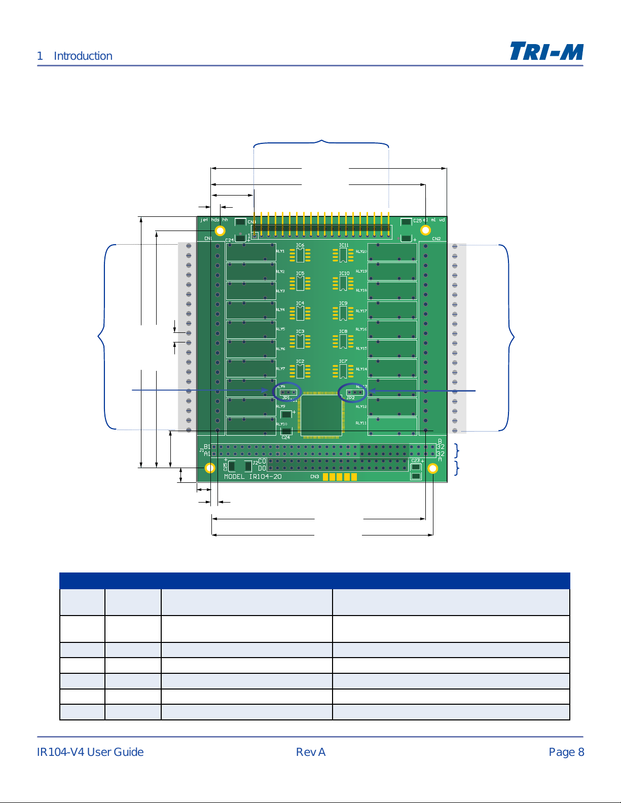
Dimensions in inches (mm)
Dimensions and Connector Locations
1 Introduction
0.63 (16.0)
0.15 (3.8)
0.14 (3.6)
CN4
3.35 (85.1)
3.05 (77.5)
CN1
3.38 (85.9 )
3.58 (90.9)
JP1
0.54 (13.7)
JP2
J1
0.20 (5.1)
0.2 (5.1)
0.10 (2.5)
3.05 (77.5)
3.15 (80.0)
Label Page Description Mechanical Specications
CN1
CN2
CN4
JP1
JP2
J1
J2
9
9
10
16
16
11
12
10 × Output Relays for 14–24 AWG wire 20 pin socket (Wieland 25.647.0553.0
mates with screw terminal block Wieland 25.640.0553.0)
10 × Output Relays for 14–24 AWG wire 20 pin socket (Wieland 25.647.0553.0
mates with screw terminal block Wieland 25.640.0553.0)
20 × Opto-isolated Inputs 2 × 20 position pin header
Jumper Block for Address Selection 3 × 1 jumper block
Jumper Block for Address Selection 3 × 1 jumper block
PC/104, 8-bit ISA PC/104 Connector 2 × 32 press-t header
PC/104 16-bit Bus PC/104 Connector 2 × 20 press-t header
J2
CN2
Artisan Technology Group - Quality Instrumentation ... Guaranteed | (888) 88-SOURCE | www.artisantg.com
Page 10
Page 9
IR104-V4 User Guide
Rev A
2 Connectors
Connector Overview
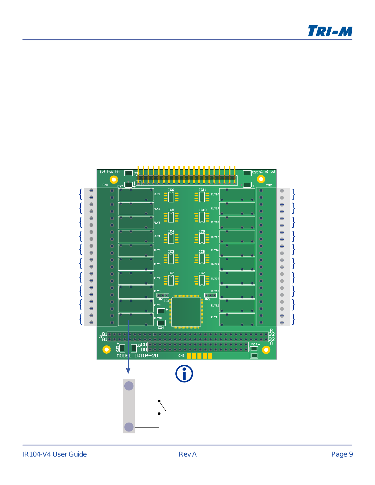
The following sections describe the pinouts and mechanical specications for the 3 connectors (CN1, CN2,
CN4) and 2 (JP1, JP2) jumper blocks.
Terminal Plugs (CN1 & CN2)
There are 20 SPST output relays with 2×20 position sockets that mate with 2×20 screw terminal block plugs
intended for 14–24 AWG wires. They have a UL certied contact rating of 5A @ 30VDC and 250VAC.
CN1
Relay 1
Relay 2
Relay 3
Relay 4
Relay 5
Relay 6
Relay 7
Relay 8
Relay 9
Relay 10
CN2
Relay 20
Relay 19
Relay 18
Relay 17
Relay 16
Relay 15
Relay 14
Relay 13
Relay 12
Relay 11
Note
The terminal sockets are Wieland 25.647.0553.0, which mate
with the screw terminal block plugs, Wieland 25.640.0553.0.
SPST relay contact example
Artisan Technology Group - Quality Instrumentation ... Guaranteed | (888) 88-SOURCE | www.artisantg.com
Page 11
Page 10
IR104-V4 User Guide
Rev A
Opto-isolated Inputs (CN4)
2 Connectors
COM
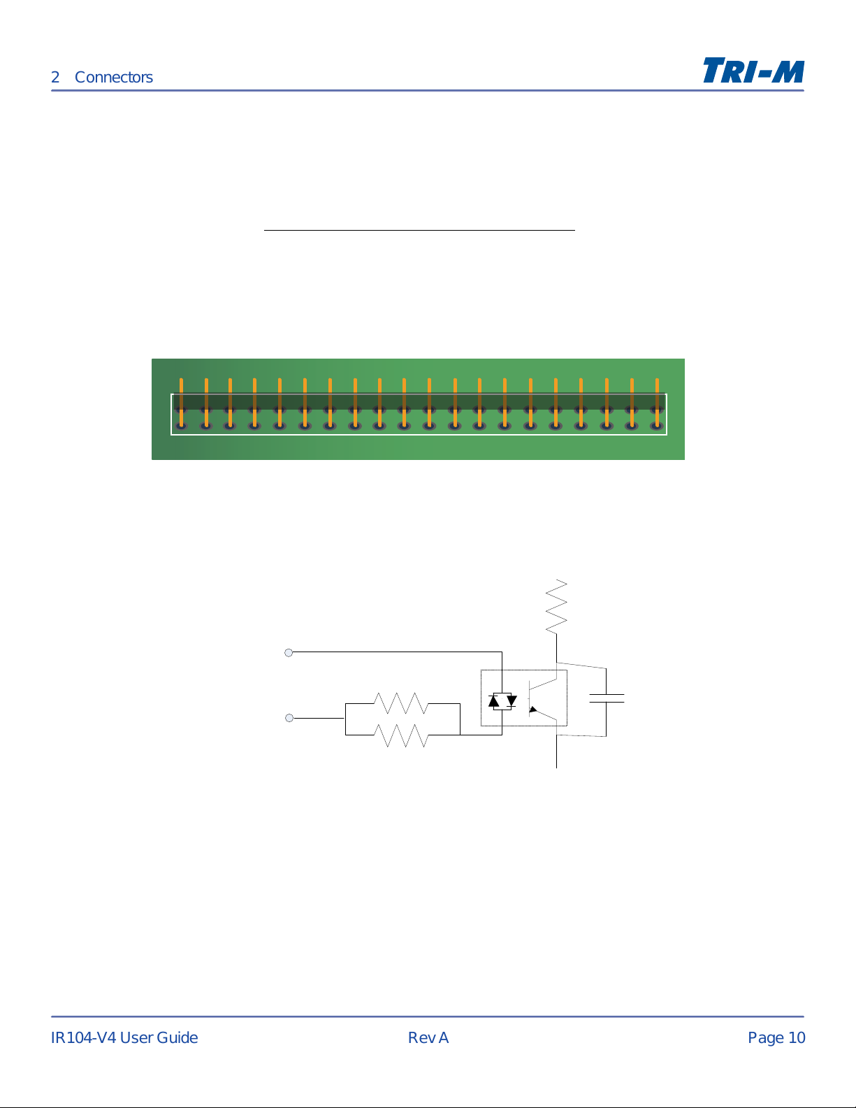
There are 20 bi-directional opto-isolated inputs with 3000V protection. They are accessed by a standard 2-row
right-angled 40-pin header, with 0.1" pin spacing. The input voltage ranges from 3V to 24V DC or AC.
For higher input voltage requirements, please contact our Professional Services Team (see "Contact
Information" on page 2) or visit http://www.tri-m.com/support/proservices.html.
CN4
1 2 3 4 5 6 7 8 9 10
2
1
3V to 24V DC or AC input
Input
Connector
11 12 13 14
PCB TOP VIEW
4.99 k
Ω
Ω
4.99 k
15 16 17 18 19
Input
Optocoupler
+5V
Pull up in PLD
0.1
20
40
39
µF
Artisan Technology Group - Quality Instrumentation ... Guaranteed | (888) 88-SOURCE | www.artisantg.com
Page 12
Page 11
IR104-V4 User Guide
Rev A
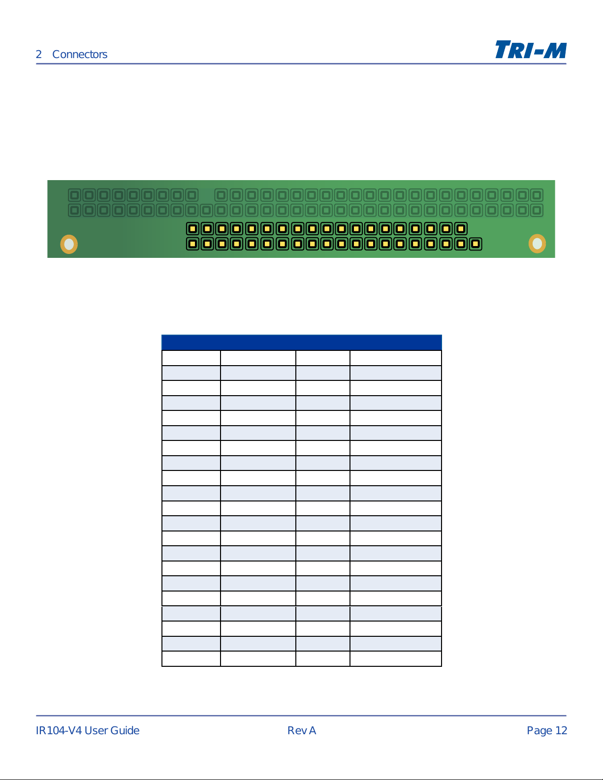
PC/104 8-bit Bus (J1)
2 Connectors
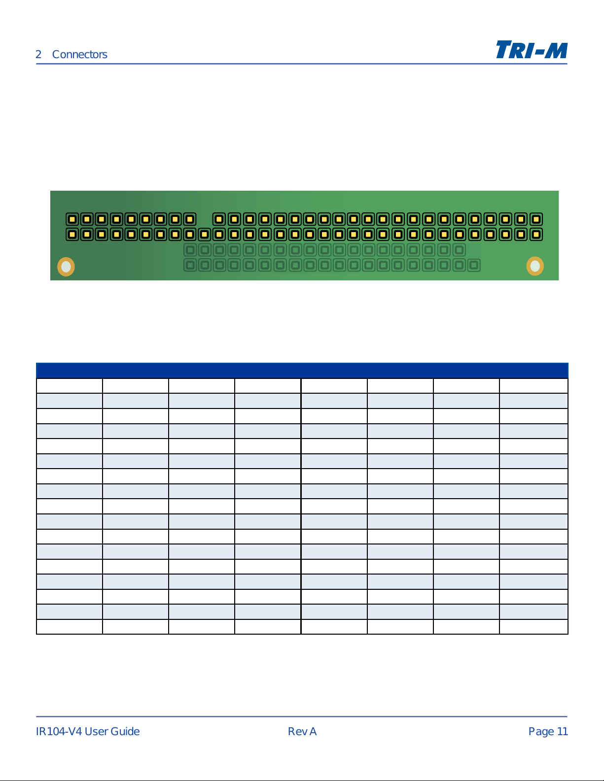
J1 is a PC/104 ISA 8-bit bus with non-pass through connectors. Tri-M also accommodates non-pass through
and non-PC/104 compliant customizations.
J1
B1
A1
B32
A32
TOP SIDE
PC/104 8-bit Connector (J1)
Pin Signal Pin Signal Pin Signal Pin Signal
A1 /IOCHCK B1 GND A17 SA14 B17 /DACK1
A2 SD7 B2 RESETDRV A18 SA13 B18 DRQ1
A3 SD6 B3 +5V A19 SA12 B19 /REFRESH
A4 SD5 B4 IRQ9 A20 SA11 B20 SYSCLK
A5 SD4 B5 -5V A21 SA10 B21 IRQ7
A6 SD3 B6 DRQ2 A22 SA9 B22 N/A
A7 SD2 B7 -12V A23 SA8 B23 IRQ5
A8 SD1 B8 /0WS A24 SA7 B24 IRQ4
A9 SD0 B9 +12V A25 SA6 B25 IRQ3
A10 IOCHRDY B10 GND A26 SA5 B26 /DACK2
A11 AEN B11 /SMEMW A27 SA4 B27 TC
A12 SA19 B12 /SMEMR A28 SA3 B28 BALE
A13 SA18 B13 /IOW A29 SA2 B29 +5V
A14 SA17 B14 /IOR A30 SA1 B30 OSC
A15 SA16 B15 DACK3 A31 SA0 B31 GND
A16 SA15 B16 DRQ3 A32
GND B32 GND
Artisan Technology Group - Quality Instrumentation ... Guaranteed | (888) 88-SOURCE | www.artisantg.com
Page 13
Page 12
IR104-V4 User Guide
Rev A
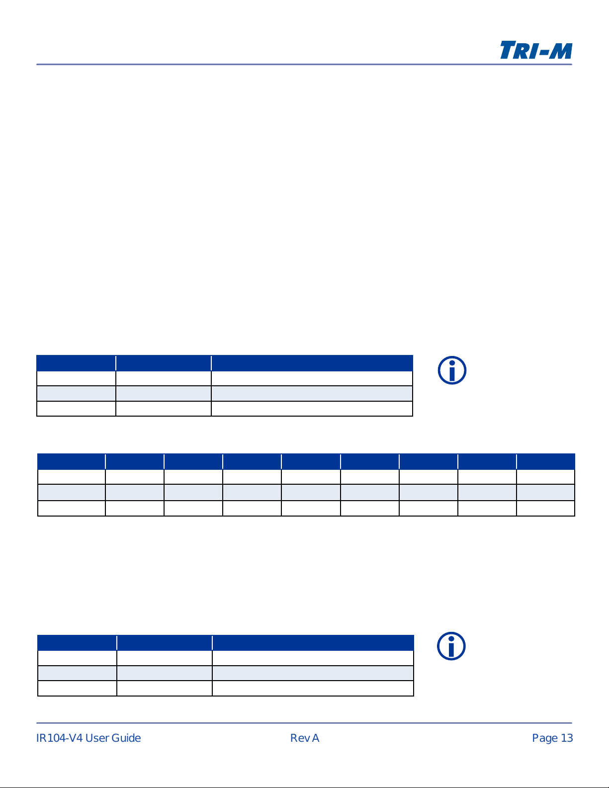
PC/104 16-bit Bus (J2)
2 Connectors
J2 is a PC/104 ISA 16-bit bus with pass through connectors. Tri-M also accommodates non-pass through and
non-PC/104 compliant customizations.
J2
C0 C19
DO
TOP SIDE
PC/104 16-bit Connector (J2)
Pin Signal Pin Signal
C0 GND D0 GND
C1 /SBHE D1 /MEMCS16
C2 LA23 D2 /IOCS16
C3 LA22 D3 IRQ10
C4 LA21 D4 IRQ11
C5 LA20 D5 IRQ12
C6 LA19 D6 IRQ15
C7 LA18 D7 IRQ14
C8 LA17 D8 /DACK0
C9 /MEMR D9 DRQ0
C10 /MEMW D10 /DACK5
C11 SD8 D11 DRQ5
C12 SD9 D12 /DACK6
C13 SD10 D13 DRQ6
C14 SD11 D14 /DACK7
C15 SD12 D15 DRQ7
C16 SD13 D16 +5V
C17 SD14 D17 /MASTER
C18 SD15 D18 GND
C19 GND D19 GND
D19
Artisan Technology Group - Quality Instrumentation ... Guaranteed | (888) 88-SOURCE | www.artisantg.com
Page 14
Page 13
IR104-V4 User Guide
Rev A
3 Conguration
I/O Map
There are four I/O maps:
• Relay Output Control (ROC)
• Digital Input Reading (DIR)
• Input Change Flags (ICF), see page 14
• Interrupts Control Register (ICR), see page 15
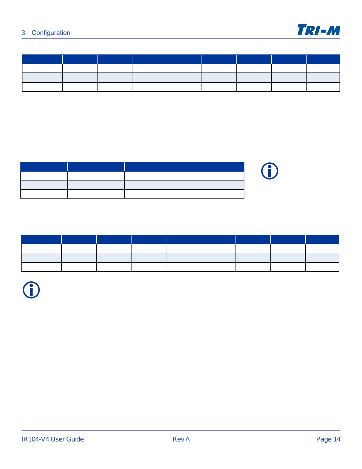
Relay Output Control (ROC)
The ROC bank energizes and de-energizes through the I/O writes. They are two grouped banks of eight and
one bank of four. When an I/O read is executed, the relay output register is accessed. This allows the relay
data to be read back. To energize a relay (close contact), write a logic “1” to the corresponding bit in the
register bank. To de-energize a relay (open contact), write a logic “0” to the corresponding bit in the register
bank.
ROC Grouping
Relay Output Address
ROC Bank 1 DO1 to DO8 I/O address = Base Address (0x00)
ROC Bank 2 DO9 to D16 I/O address = Base Address + 1 (0x01)
ROC Bank 3 DO17 to DO20 I/O address = Base Address + 2 (0x02)
ROC I/O Map
Relay SD7 SD6 SD5 SD4 SD3 SD2 SD1 SD0
ROC Bank 1 Relay 8 Relay 7 Relay 6 Relay 5 Relay 4 Relay 3 Relay 2 Relay 1
ROC Bank 2 Relay 16 Relay 15 Relay 14 Relay 13 Relay 12 Relay 11 Relay 10 Relay 9
ROC Bank 3 Not used Not used Not used Not used Relay 20 Relay 19 Relay 18 Relay 17
Note
The I/O address is an
offset from the base
decoded address.
Digital Input Reading (DIR)
The DIR bank is accessed through I/O reads and are grouped in two banks of eight and one bank of four. A
logic “0” read for an input indicates the corresponding physical input is “powered”. A logic “1” read on any input
indicates the corresponding physical input is “non-powered”.
DIR Grouping
Bank Input Address
DIR Bank 1 DI1 to DI8 I/O address = Base Address + 4 (0×04)
DIR Bank 2 DI9 to DI16 I/O address = Base Address + 5 (0×05)
DIR Bank 3 DI17 to DI20 I/O address = Base Address + 6 (0×06)
Note
The I/O address is an
offset from the base
decoded address.
Artisan Technology Group - Quality Instrumentation ... Guaranteed | (888) 88-SOURCE | www.artisantg.com
Page 15
Page 14
IR104-V4 User Guide
Rev A
3 Conguration
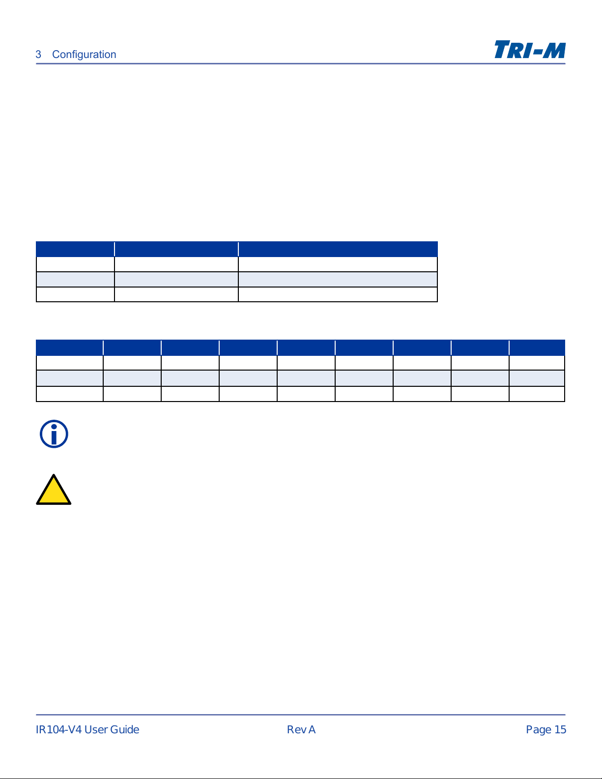
DIR I/O Map
Bank SD7 SD6 SD5 SD4 SD3 SD2 SD1 SD0
DIR Bank 1 Input 8 Input 7 Input 6 Input 5 Input 4 Input 3 Input 2 Input 1
DIR Bank 2 Input 16 Input 15 Input 14 Input 13 Input 12 Input 11 Input 10 Input 9
DIR Bank 3 Not used Not used Not used Not used Input 20 Input 19 Input 18 Input 17
Input Change Flags (ICF)
When a change is detected on one of the inputs, the corresponding bit in the ICF register is set to logic “1”.
The input change ags are accessed through I/O reads and are grouped in two banks of eight and one bank of
four.
ICF Grouping
Bank Flags Address
ICF Bank 1 F1 to F8 I/O address = Base Address + 8 (0×08)
ICF Bank 2 F9 to F16 I/O address = Base Address + 9 (0×09)
ICF Bank 3 F17 to F20 I/O address = Base Address + 10 (0×0A)
ICF I/O Map
Bank SD7 SD6 SD5 SD4 SD3 SD2 SD1 SD0
ICF Bank 1 Flag 8 Flag 7 Flag 6 Flag 5 Flag 4 Flag 3 Flag 2 Flag 1
ICF Bank 2 Flag 16 Flag 15 Flag 14 Flag 13 Flag 12 Flag 11 Flag 10 Flag 9
ICF Bank 3 Not used Not used Not used Not used Flag 20 Flag 19 Flag 18 Flag 17
Note
The I/O address is an
offset from the base
decoded address.
Note
An input change ag can be cleared by reading the corresponding input bank.
Artisan Technology Group - Quality Instrumentation ... Guaranteed | (888) 88-SOURCE | www.artisantg.com
Page 16
Page 15
IR104-V4 User Guide
Rev A
Interrupts Control Register (ICR)
!
3 Conguration
The ICR I/O map has one Interrupt Enable (IE) per input and four Interrupt Output enables (IRQen4, IRQen5,
IRQen6 and IRQen7). Each of the Interrupt Outputs correspond to a PC/104 interrupt line. Only one Interrupt
Output should be enabled.
Interrupts are generated and issued on the PC/104 Bus when ALL of the following conditions are met:
1. A change of input state has occurred indicated by the Flag registers.
2. The input that changed has its Interrupt Enable set (logic “1”).
3. One of the Interrupt Output Enables is set (logic “1”).
ICR Grouping
Bank Interrupts Address
ICR Bank 1 IE1 to IE8 I/O address = Base Address + 12 (0x0C)
ICR Bank 2 IE9 to IE16 I/O address = Base Address + 13 (0x0D)
ICR Bank 3 IE17 to IE20 & IRQen4 to 7 I/O address = Base Address + 14 (0x0E)
ICR I/O Map
Bank SD7 SD6 SD5 SD4 SD3 SD2 SD1 SD0
ICR Bank 1 IE8 IE7 IE6 IE5 IE4 IE3 IE2 IE1
ICR Bank 2 IE16 IE15 IE14 IE13 IE12 IE11 IE10 IE9
ICR Bank 3 IRQen7 IRQen6 IRQen5 IRQen4 IE20 IE19 IE18 IE17
Note
An Interrupt will stay asserted until all the Input Change Flags that have their Interrupt Enabled ags enabled are cleared. An
input change ag can be cleared by reading the corresponding input bank.
CAUTION: Equipment Damage
The IR104-V4 interrupts cannot be shared with other PC/104 boards. Attempting to share an IRQ may cause damage to the
IR104-V4 and the other PC/104 board as well.
Artisan Technology Group - Quality Instrumentation ... Guaranteed | (888) 88-SOURCE | www.artisantg.com
Page 17
Page 16
IR104-V4 User Guide
Rev A
Base Addresses
3 Conguration
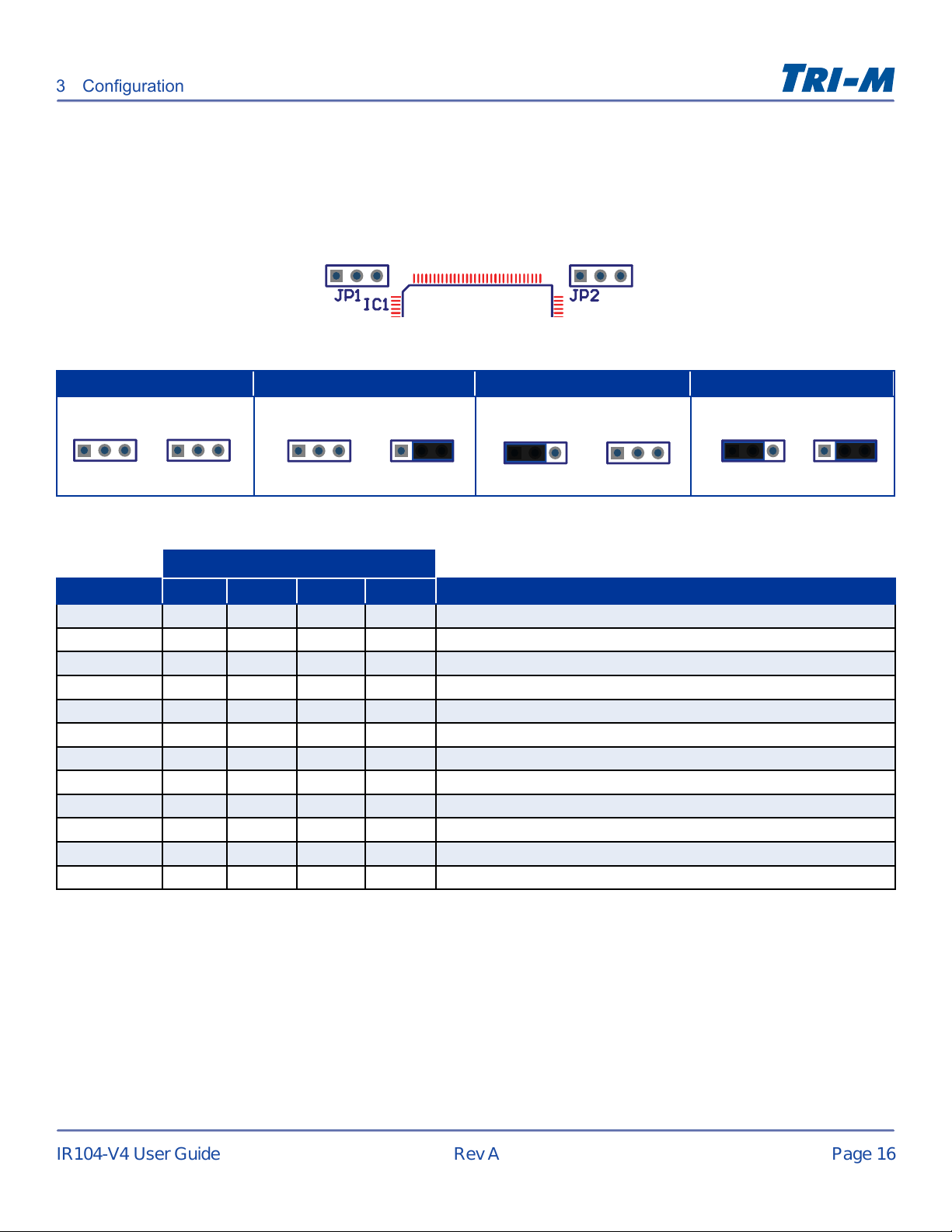
There are four decoded base addresses: 0x240, 0x260, 0x280, and 0x300. They are jumper selectable using
the address select blocks JP1 and JP2.
0x240 0x260 0x280 0x300
JP1 JP2
1 1
Not Installed Not Installed
JP1 JP2
1 1
JP1 JP2
1 1
Installed Not Installed
Not Installed Installed
JP1 JP2
1 1
Installed Installed
Base Address
Register 0x240 0x260 0x280 0x300 Description
ROC Bank 1 0x240 0x260 0x280 0x300 Relays 1 to 8
ROC Bank 2 0x241 0x261 0x281 0x301 Relays 9 to 16
ROC Bank 3 0x242 0x262 0x282 0x302 Relays 17 to 20
DIR Bank 1 0x244 0x264 0x284 0x304 Inputs 1 to 8
DIR Bank 2 0x245 0x265 0x285 0x305 Inputs 9 to 16
DIR Bank 3 0x246 0x266 0x286 0x306 Inputs 17 to 20
ICF Bank 1 0x248 0x268 0x288 0x308 Change Flag Inputs 1 to 8
ICF Bank 2 0x249 0x269 0x289 0x309 Change Flag Inputs 9 to 16
ICF Bank 3 0x24A 0x26A 0x28A 0x30A Change Flag Inputs 17 to 20
ICR Bank 1 0x24C 0x26C 0x28C 0x30C Interrupt Enables Inputs 1 to 8
ICR Bank 2 0x24D 0x24D 0x28D 0x30D Interrupt Enables Inputs 9 to 16
ICR Bank 3 0x24E 0x26E 0x28E 0x30E Interrupt Enables Inputs 17 to 30 & IRQ output enables 4, 5, 6 & 7
Artisan Technology Group - Quality Instrumentation ... Guaranteed | (888) 88-SOURCE | www.artisantg.com
Page 18
Page 17
IR104-V4 User Guide
Rev A
Warranty and Product Information
Tri-M Technologies Inc. (Limited Warranty)
Unless otherwise agreed to in writing, Tri-M Technologies Inc. (Tri-M) warrants to the original purchaser that its products
will be free from defects in material and workmanship for a period of (1) one year from the date of shipment. Tri-M’s
obligation under this warranty is limited to replacement or repair at its option and its designated site. Any such products
must be returned within the warranty period to Tri-M in Tri-M approved packaging with a Tri-M-assigned RMA (Return
Material Authorization) number referenced on the shipping documents.
All warranties are void if there is evidence of misuse, tampering, or attempted repair of parts. Any returns must be
accompanied by a return material authorization (RMA) number issued by Tri-M. Purchaser shall prepay transportation
to Tri-M’s designated site. If returned products are repaired or replaced under the terms of this warranty, Tri-M shall pay
return transportation charges.
In no case will Tri-M be held liable for consequential damages arising out of its obligations under this warranty or the
failure or incorrect use of any of its products. This warranty is in lieu of all warranties, either express or implied, including,
without limitation, any implied warranty of merchantability or tness for any particular purpose, and of any other obligation
on the part of Tri-M.
Disclaimer
No part of this document may be reproduced, transmitted, transcribed, stored in a retrieval system, or translated into
any language or computer language, in any form or by any means, electronic, mechanical, magnetic, optical, chemical,
manual, or otherwise, without the express written permission of Tri-M Technologies Inc.
Tri-M Technologies Inc. (Tri-M) makes no representations or warranties with respect to the contents of this manual, and
specically disclaims any implied warranties of merchantability or tness for any particular purpose. Tri-M shall under
no circumstances be liable for incidental or consequential damages or related expenses resulting from the use of this
product, even if it has been notied of the possibility of such damages. Tri-M reserves the right to revise this publication
from time to time without obligation to notify any person of such revisions.
Copyright © 2012 Tri-M Technologies Inc. All rights reserved.
Artisan Technology Group - Quality Instrumentation ... Guaranteed | (888) 88-SOURCE | www.artisantg.com
Page 19

Page 18
IR104-V4 User Guide
Rev A
Appendix
Frequently Asked Questions (FAQ)
What is the mating connector for relay connectors (CN1, CN2)?
IR104’s relay socket terminals (CN1, CN2) use Wieland’s Part# 25.647.0553.0. The mating screw plug terminal block is
Wieland Part# 25.640.0553.0.
What happens to the IR104’s relays on a power-up or hardware reset?
Ensured by design on IR104-V3 (version 3) and higher versions, the relays are de-energized and the contacts open on a
power-up or hardware reset.
What options are available on the IR104?
There are a variety of options available for the IR104, such as conformal coating, connectors, and custom designs.
Custom builds include 12V and solid state relays. For more information about these options, please contact us. See
"Contact Information" on page 2.
I have an older version of IR104, what’s new in IR104-V4 (version 4)?
New features include input change ags, interrupt enables, and software IRQ selection.
Is the IR104-V4 software compatible with other IR104 version?
IR104 software support is compatible with previous versions. All new features have been set in previously unused I/O
registers.
Is the IR104 RoHS Compliant?
All Tri-M’s products are RoHs, and we also provide other customizable options depending on your requirements.
What is the MTBF?
The IR104 MTBF is rated at 57,098 hours at 30°C (86°F) ambient temperature.
What is IR104-V4’s OS support?
The IR104 does not come with any software. I/O mapped registers are supported by any system with ISA support. An OS
using x86 protected mode requires I/O driver support such as Linux ioperm or Windows® PortTalk.
How do I request an RMA or warranty issue?
To request an RMA, please ll out the online form on our website at www.tri-m.com/support .
What if I have a technical or specic question?
For technical support, please see "Contact Information" on page 2.
Artisan Technology Group - Quality Instrumentation ... Guaranteed | (888) 88-SOURCE | www.artisantg.com
Page 20

Artisan Technology Group is your source for quality
new and certied-used/pre-owned equipment
• FAST SHIPPING AND
DELIVERY
• TENS OF THOUSANDS OF
IN-STOCK ITEMS
• EQUIPMENT DEMOS
• HUNDREDS OF
MANUFACTURERS
SUPPORTED
• LEASING/MONTHLY
RENTALS
• ITAR CERTIFIED
SECURE ASSET SOLUTIONS
SERVICE CENTER REPAIRS
Experienced engineers and technicians on staff
at our full-service, in-house repair center
Instra
Remotely inspect equipment before purchasing with
our interactive website at www.instraview.com
Contact us: (888) 88-SOURCE | [email protected] | www.artisantg.com
SM
REMOTE INSPECTION
View
WE BUY USED EQUIPMENT
Sell your excess, underutilized, and idle used equipment
We also offer credit for buy-backs and trade-ins
www.artisantg.com/WeBuyEquipment
LOOKING FOR MORE INFORMATION?
Visit us on the web at www.artisantg.com for more
information on price quotations, drivers, technical
specications, manuals, and documentation
 Loading...