

Page 1

SYSTEM MANUAL
LIVELINK
Page 2

CONTENTS
Page 2 / 77
Introduction 3
Basic functions 3
Safety instructions 3
App download 3
System overview 4
Controller 5
Push-button coupler 6
Sensors 7
· Technical Data 8
· Sensor placement 10
WLAN 11
· Connect to WLAN 11
· Utilising the WLAN with the infrastructure 12
· WLAN security 12
Access data 13
Behaviour of light control 14
· Behaviour in delivery condition 14
· Behaviour in operation 14
“LiveLink Install” app 19
Overview 19
What is a Use Case? 20
· Public Use Cases 20
· Private Use Cases 26
· Universal Use Case 26
Use Case administration 27
· Administrating public Use Cases 28
· Administrating private Use Cases 29
Room administration 30
· Room setup 31
· Room setup: Use Case 33
· Room setup: Assignment 37
· Room setup: Assigning push-buttons 44
· Concluding the room setup 48
· Room setup: Option “Rename room” 49
· Room setup: Option “Administrate scenes” 51
· Room setup: Option “Setting up scenes” 54
· Room administration 59
· Settings 60
· Settings: DALI fade time 61
· Settings: Reset LiveLink and hardware reset 61
· Settings: Advanced sensor settings 62
· Settings: Update firmware 64
· Settings: Change passwords 65
· WLAN: Connect to infrastructure 66
Operating the light control 69
“LiveLink Control” app 70
Overview 70
Select room 71
Manual setting of the room illumination 72
Activation of illumination scenarios 73
FAQ 74
Page 3

INTRODUCTION / BASIC FUNCTIONS
INTRODUCTION
BASIC FUNCTIONS
Page 3 / 77
LiveLink is a light control system that provides for automatic and/or
semi-automatic control for optimal quality and efficiency of illumination. The innovative operation by means of table and smart phone
provides maximum comfort for setup and operation.
LiveLink can be configured to be commensurate with a demand-oriented operation of luminaires. All luminaires and sensors that are
connected must be equipped with a DALI interface (Digital Addressable Lighting Interface). Luminaires, sensors and push-buttons are
connected per room to a LiveLink control device, wherein a room does
not necessarily have to correspond to a physical room.
The system is setup via tablet and operated via tablet or smart phone.
The highest security standards are being complied with in this (also
see chapter “WLAN Security”).
SAFETY INSTRUCTIONS
• Work on electric devices may only
be carried out while disconnected from electric power.
• Applicable safety and accident prevention regulations must be
adhered to.
• Regarding installation, please adhere to the corresponding instal-
lation steps from the installation instructions of the luminaire to
be installed.
Connectivity to an existing network structure is possible.
Available for setup are Use Cases which contain a pre-configuration
of luminaire groups and light scenes. Through further configuration,
each room can be individually attuned to the respective needs.
LiveLink is not intended for any application other than the one listed here.
Other applications are considered to be in violation of the intended use.
If LiveLink is used improperly, a safe operation cannot be guaranteed.
APP DOWNLOAD
“LiveLink Install” app
The system is set up with the “LiveLink Install” app. System prerequisite is an iOS or Android tablet.
“LiveLink Control” app
The “LiveLink Control” app provides for a comfortable operation of the
room lighting. System prerequisite is an iOS or Android tablet and/or
smart phone.
www.trilux.com/livelink-app
Page 4

INTRODUCTION / SYSTEM OVERVIEW Page 4 / 77
SYSTEM OVERVIEW
LiveLink contains only one hardware component, the LiveLink control
device. Luminaires, sensors, push-buttons and/or push-button couplers are connected to the LiveLink control device via DALI.
In addition, LiveLink includes two software components: The “LiveLink Install” tablet app for the setup of the system by expert personnel, and the “LiveLink Control” tablet and/or smart phone app for the
control of the illumination by the end user.
The tablet and/or smart phone communicate directly with the control
device which is equipped with a WLAN of its own (access point) for this
purpose. But, as an alternative, the LiveLink control device can also
be integrated into the network structure of the building.
Sensor
Control gear
Direct connection for 1 push-button
Option
Connection to a building network structure
Push-button coupler
The controlling of the lighting can be performed in two ways:
1. The activating of light scenes or switching and dimming of luminaire groups can be carried out with commercial push-buttons via
the DALI installation.
In addition, a push-button can be connected directly to the LiveLink
control device.
2. Control via the “LiveLink Control” app. The app provides for access
to all light scenes and individual control of luminaire groups.
Page 5
INTRODUCTION / CONTROLLER Page 5 / 77
250
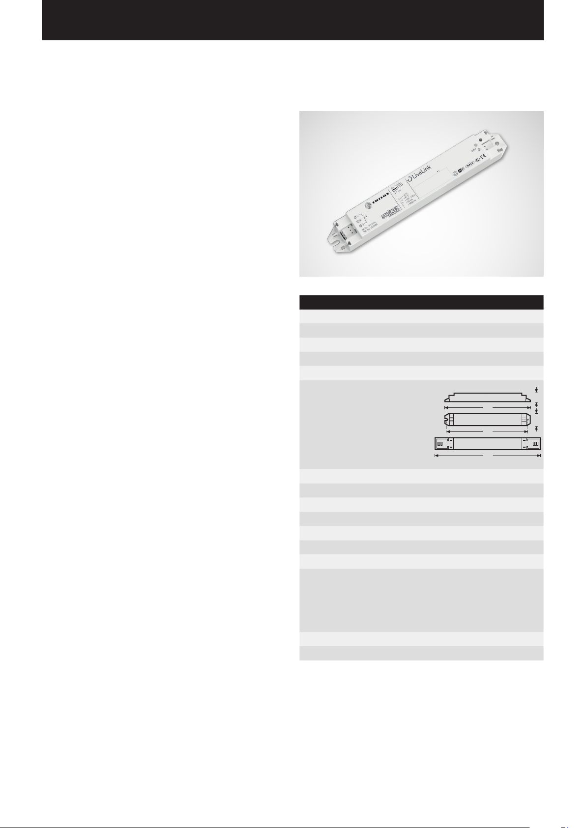
CONTROLLER
The control device – the intelligent command centre.
The core element of the LiveLink control device is a Linux-based
high-performance minicomputer which processes the incoming data
streams and issues control commands to the system components.
For a particularly straight-forward communication with the user,
the control device is equipment with an integrated WLAN module for
controlling via tablet or smart phone.
Compact design – great leeway.
Thanks to its compact dimensions with a construction depth of only
21 millimetres, the control device itself can fit without a problem even
underneath shallowly suspended ceilings. Upon request it is also
available integrated directly into a luminaire (master luminaire).
DALI interface for clever light management.
With the universal DALI interface, DALI-capable luminaires, sensors,
and push-buttons can be integrated, configured, and controlled effortlessly. Each control device can individually address up to 16 luminaire
groups. The maximum number of DALI participants is 64.
Comfortable control via tablet or push-button.
The luminaires and/or groups of luminaires can be controlled either
with a commercial installation push-button or via mobile app on a tablet or smart phone. Additional push-buttons can be connected via an
optional LiveLink DALI push-button coupler that is simply integrated
into the DALI control circuit. The push-button can be configured freely
– this way, “offline” groups of luminaires can be controlled, too, or
light scenarios called up.
Autarkic encryption for more security.
For protection against external access, the control device is equipped
with a WLAN network with autarkic encryption. This way, the system
remains unaffected by cyber attacks against the general computer
network.
Configuration survives power outage.
No reprogramming is required after a power outage; the system configuration is stored in the control device.
Technical Data
Weight 76 g
Input voltage 220-230 V
Input current max. 50 mA
Input frequency 50/60 Hz
Standby power consumption <2 W
Measurements
204
190
22
30
DALI participants max. 64
WiFi IEEE 802.11b
WiFi encryption WPA2
WiFi range max. 25 m
Protection rating IP20
Temperature of case tc max 85 °C
Ambient temperature ta max 65°C
Standards: IEC 61347-2-11
EN 55015
EN 61000-32
EN 61000-33
EN 61000-547
IEC 62386
Cable length for DALI max. 300 m
Cable length for push-button max. 25 m
Page 6
INTRODUCTION / PUSH-BUTTON COUPLER
LiveLink DALI PB4
T5T4T3T2
L= max. 25 m
3 4 765
N
DALI 1
DALI 2
L
S
(T1)
LiveLink WiFi
1
2
16
11
LiveLink DALI PB4
T5T4T3T2
L= max. 25 m
3 4 765
N
DALI 1
DALI 2
L
S
(T1)
LiveLink WiFi
1
2
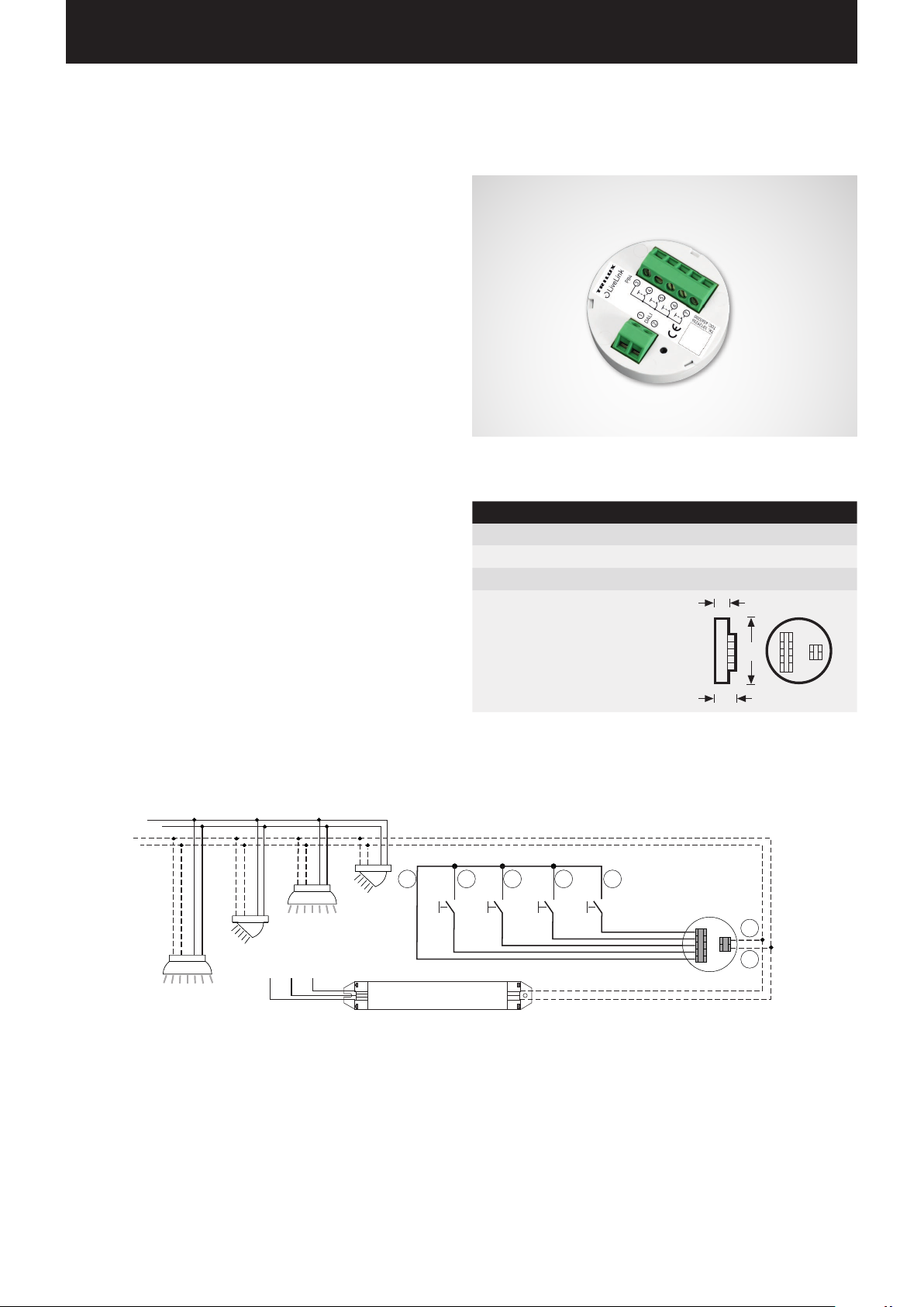
PUSH-BUTTON COUPLER
Interface for commercial installation push-buttons
The push-button coupler integrates additional push-buttons into a
LiveLink system. For this, up to 4 commercial installation push-buttons
can be connected to each push-button coupler. The push-button
coupler
passes the signals on to the LiveLink control device via DALI.
The function of the push-buttons is freely programmable during
commissioning.
Fits into the flush device box
The compact dimensions allow for an installation in flush device boxes
with a minimum depth of 60 mm. The push-button cables may have
maximum length of 25 m and must be installed in a separate plasticsheathed cable. The connections at the push-button coupler are not
suited to mains voltage.
Page 6 / 77
Technical Data
Number of push-buttons 4
Cable length for push-button max. 25 m
Number of DALI participants 1
Dimensions
50
Page 7

INTRODUCTION / SENSORS Page 7 / 77
SENSORS
Any brain needs its sensory organs – and any light management
system its sensors.
Light only then and there where it is desired, and as bright as necessary.
For a light control commensurate with the requirements, the framework conditions must be detected precisely. This task is handled by
the intelligent sensor technology of STEINEL.
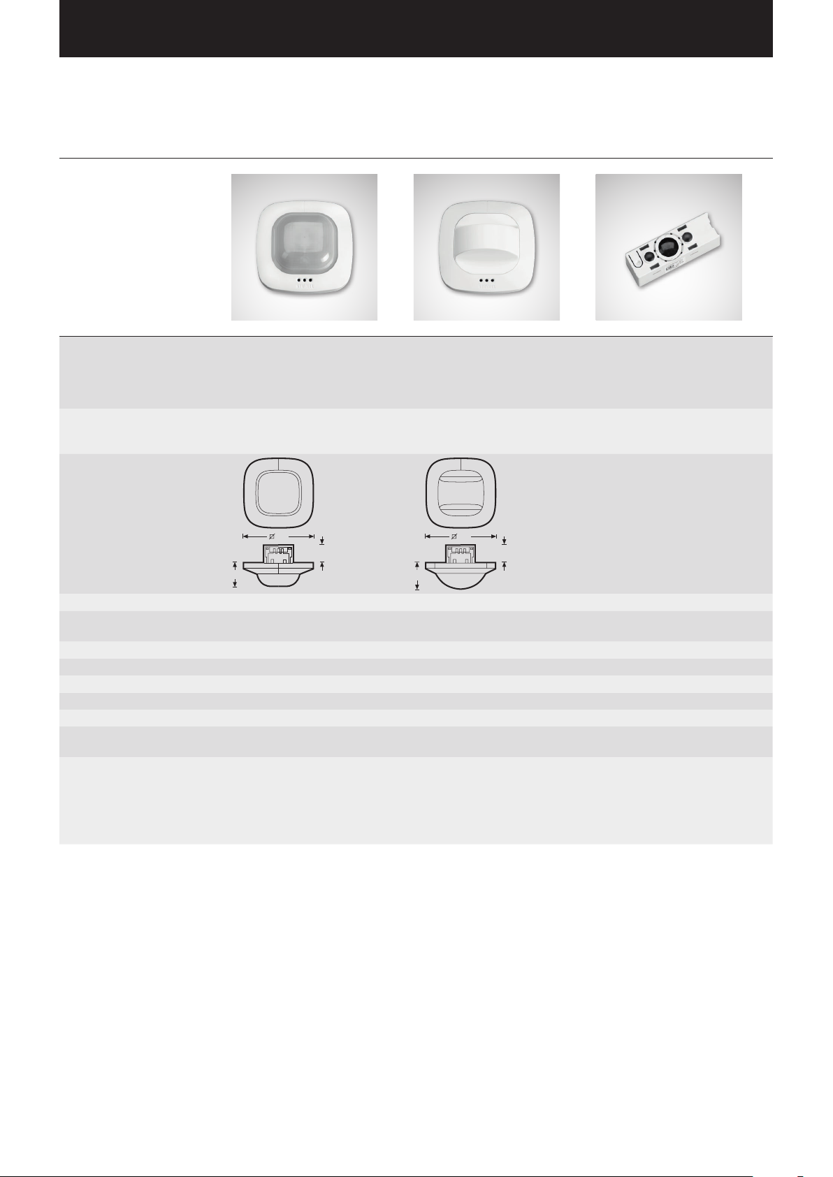
Dual HF. Doubly convincing across the board.
The high frequency corridor sensor Dual HF, with its detection area
of 20 x 3 metres, is suitable for long corridors. Decisive for a corridor
sensor is how well radial movements are detected. This refers to the
frontal direction of walking towards the sensor. The STEINEL high
frequency technology masters this perfectly.
Equipment and functions:
• Two integrated HF sensors with dual directional characteristic
for up to 20 metres of radial detection
• Detects equally well from any direction of walking
• Continuously variable, electronic setting
IR Quattro HD. Detects the most minute of movements all the way
into any corner.
The infra-red presence detector IR Quattro HD is ideal for medium to
large offices, conference rooms and meeting rooms as well as classrooms and lecture halls. Its high resolution detection is ideal in case
of sitting activities.
Equipment and functions:
• Highest quality of detection due to 4 pyro sensors
with 4,800 switching zones per 64 m
• Straight-forward planning with square detection area
• Quick setting due to patented mechanical scalability
without loss of quality
• 8 x 8 metres presence detection, 8 x 8 metres radial detections,
and 20 x 20 metres tangential detection
• Suitable for ceiling heights from 2.5 up to 10 metres
2
Page 8
INTRODUCTION / SENSORS / TECHNICAL DATA Page 8 / 77
30
40
30
45
TECHNICAL DATA
Type Quattro HD Dual HF LS/PD LI
Characteristics
• Square detection area typical
for a room
• Particularly high sensitivity
and range
• Dual directional characteristic
for targeted detection of hallways and corridors
• Temperature-independent
• Compact design for installation in
luminaire or, optionally, in ceilings
• Upon request, available installed
in a LiveLink master luminaire
detection
Sensor type • Passive infra-red presence
sensor (PIR)
• Light sensor
• HF sensor
• Light sensor
• Passive infra-red presence
sensor (PIR)
• Light sensor
Dimensions (H x W x D)
120
120
Site of operation In the interior area of buildings In the interior area of buildings In the interior area of buildings
Sensor system 13 detection areas,
4800 switching zones
High frequency 5.8 GHz,
transmitting power < 1 mW
Light value setting 10-1000 Lux 10-1000 Lux 20-800 Lux
Protection rating IP20 (IP54 with AP box) IP20 (IP54 with AP box) IP20
Protection class II II II
Temperature range 0 °C to +40 °C 0 °C to +40 °C -20 °C to +50 °C
Number of DALI participants 2 7 2
Height of installation
2.5 - 10 m 2.5 - 3.5 m 2 - 5 m
(ceiling mount)
Detection angle/
square
Presence; max. 8 x 8 m (64 sqm)
Circular: max. 8 x 8 m (64 sqm)
Tangentially: max. 20 x 20 m (400 sqm)
see diagram;
Where applicable, through glass,
wood and lightweight walls;
max. diameter 7.0 m
Range max. 10 x 3 m,
electronically adjustable in each
direction continuously variable
Page 9
INTRODUCTION / SENSORS / TECHNICAL DATA Page 9 / 77
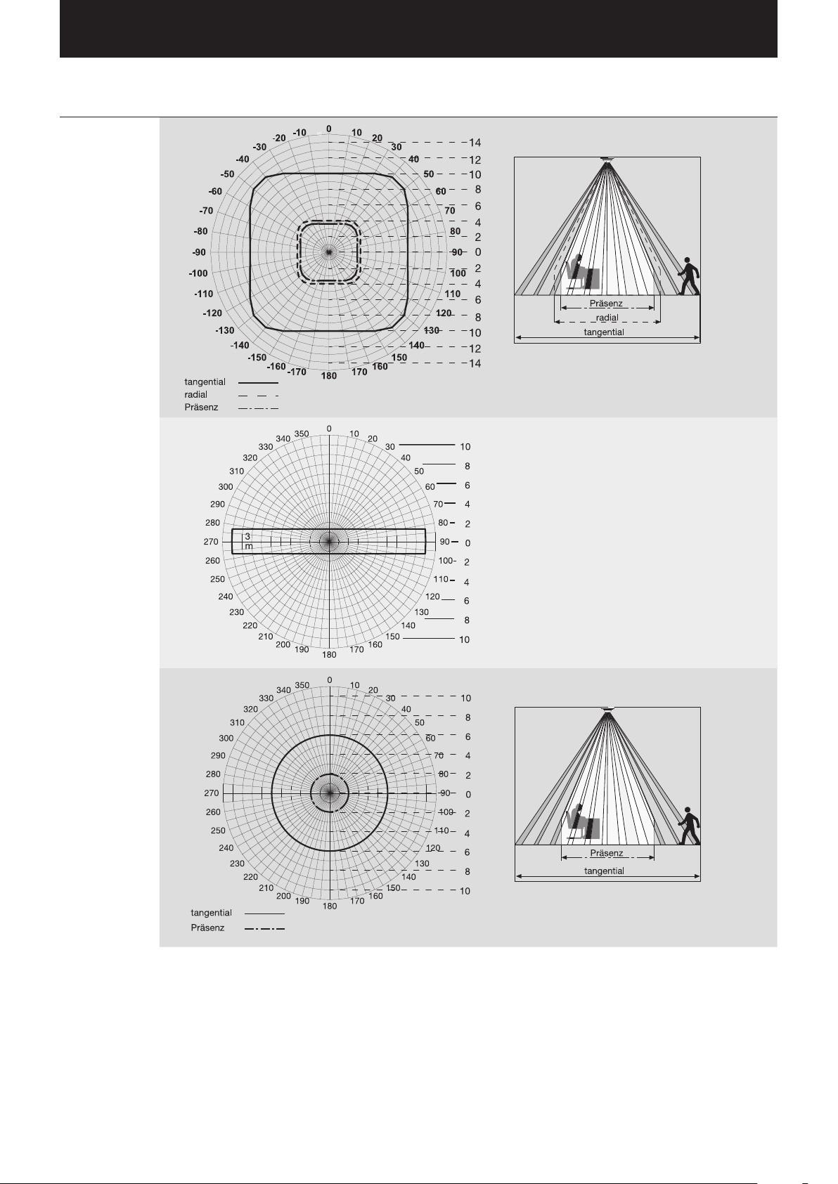
Type Detection ranges (at a height of installation of 2.8-3.0 m)
Quattro HD
Dual HF
LS/PD LI
Presence
Circular
Tangentially
Page 10
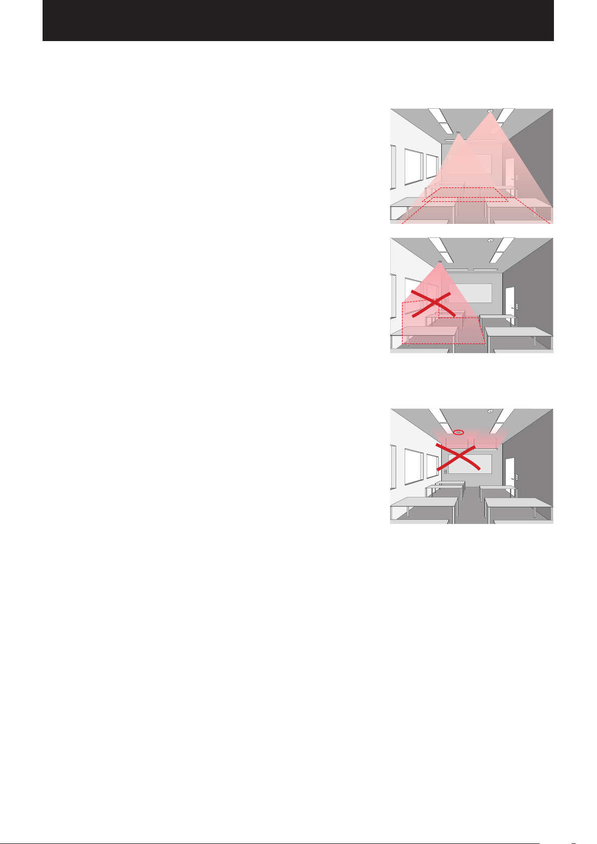
INTRODUCTION / SENSORS / SENSOR PLACEMENT Page 10 / 77
SENSOR PLACEMENT
Detection area
• The detection area of the sensor must be taken into consideration (see sensor’s product
data sheet). On the one hand, the sensor should detect areas of work and movement in the
room but, on the other, also the entrance so that the light can be switched on early on. If the
detection area is insufficient, additional sensors must be planned for.
• When using HF and/or radar sensors, it must be taken into consideration that a detection
through thin walls may occur. In addition, the narrow detection area (see product data sheet)
must be taken into consideration.
Light sensor
For the functioning of the daylight control, it is important that the light sensor and/or combined
presence and light sensor be position in a suitable location.
• The light sensor should not be positioned too close to window areas but also not too far into
the depth of the room.
• The sensor should be positioned where it receives an average intensity of daylight, for example
in the middle of the room or near work spaces to which the light control will be calibrated.
• If possible, the light sensor should be positioned above a suitable area. Ideally, this area
should also be utilised as reference area for the calibration of the illuminance. If possible,
this area should feature an average reflectance value. Well suited are, for example desk
surfaces or light-grey path areas.
• It should also be taken into consideration that no items be placed underneath the sensor
that have an influence on the function of the light sensor, e.g. pallets or higher pieces of
furniture.
Sources of interference
Any positioning near the following sources of interference should be avoided:
• Ventilation systems or heat sources, e.g. Heaters or also overhead projectors
• Interference sources of light such as luminaires the indirect light share of which radiates
directly onto the sensor
• Daylight reflections, e.g. by mirrors
• Radio and/or WLAN transmitters at a distance of approx. one metre
Page 11
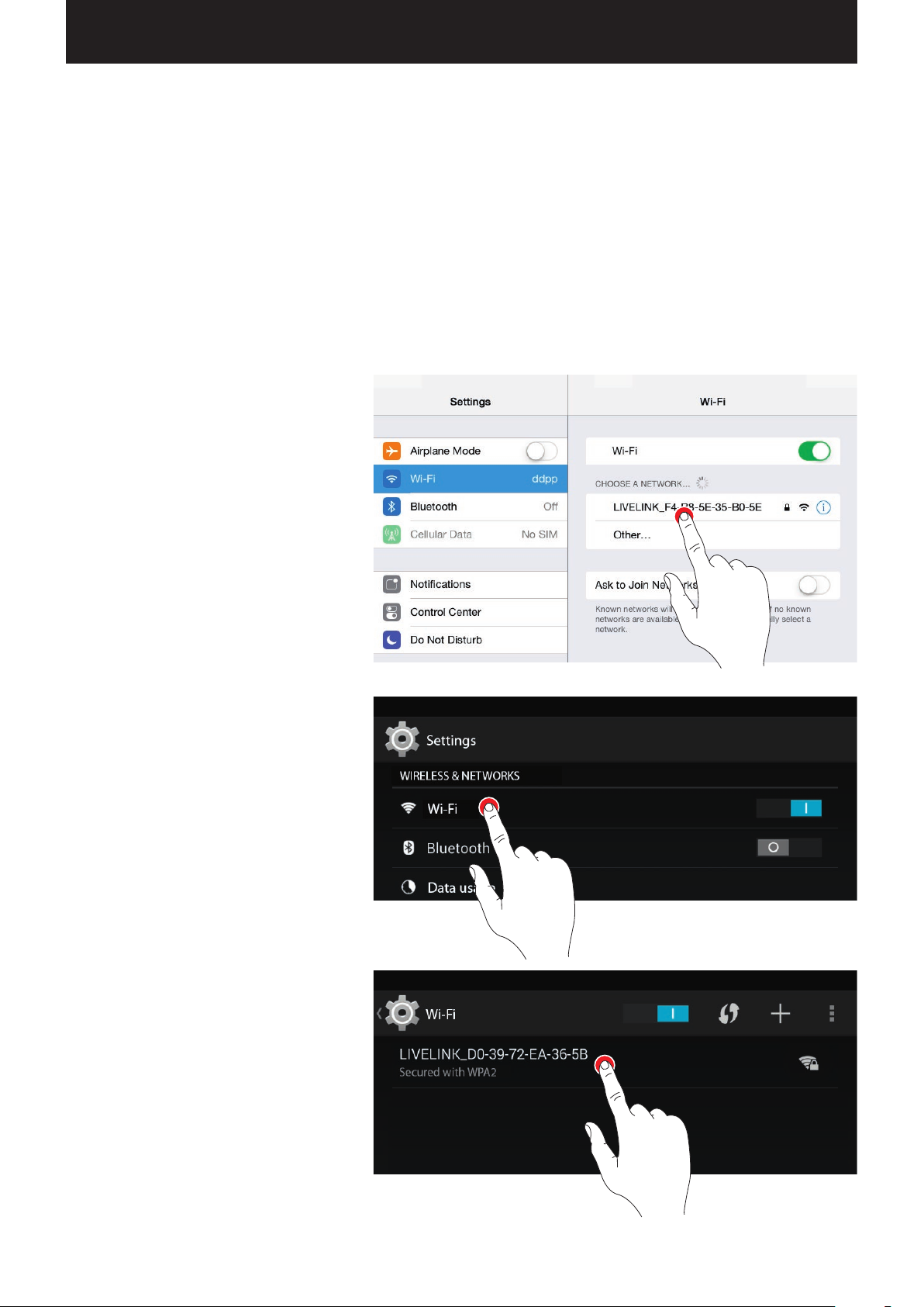
INTRODUCTION / WLAN Page 11 / 77
WLAN
The setup or control of the LiveLink system via tablet and/or smart
phone app does only work in case of an existing WLAN connection
with the LiveLink control device.
In delivery condition, the LiveLink control device makes available a
WLAN of its own for a direct connection (AdHoc connection). Each
CONNECT TO WLAN
Selecting the WLAN with an iOS device
In the menu item “WLAN” of the device settings, all
available WLANs are listed.
Upon tapping the “LIVELINK...” WLAN, the connection
is established. The exact name (SSID) of the respective WLAN is located on the control device. The
WLAN password is “livelink”.
control device bears a WLAN name of its own, starting with “LIVELINK”, that is printed onto the control device. The WLAN name can be
changed later, see chapter “Room setup: room name”.
Optionally, the control device can be connected to an existing network
infrastructure and utilised from there.
Selecting the WLAN with an Android device
In the menu item “WLAN” of the device settings, all
available WLANs are listed.
U
pon tapping the “LIVELINK...” WLAN, the connec-
tion is established. The WLAN password is “livelink”.
Page 12

INTRODUCTION / WLAN Page 12 / 77
UTILISING THE WLAN WITH THE INFRASTRUCTURE
Instead of a direct WLAN connection between the iOS and/or Android
device and the LiveLink control device, an existing infrastructure can
also be utilised subsequent to the initial setup.
WLAN SECURITY
The WLAN access to the LiveLink control device is protected with a
three-tiered security concept.
1. In the first step, a password for the WLAN must be entered
(WPA2 encryption).
2. In the second step, a connection is established via https. This is an
asymmetrical encryption. Data that is transmitted from the app to
the LiveLink system, and vice versa, can not be read in transit.
3. In the third step, a user authentication ensures that only those who
are in possession of the administration and/or user password can
connect to the system and as a result make changes.
For this, the control device can be connected to the existing building
WLAN. The configuration takes place in the administrator menu, see
chapter “Room administration”.
The iOS and/or Android app can then also be used in the building
WLAN. Available to the apps are all LiveLink rooms that are, in turn,
connected to the building WLAM.
In this, the user access is set up restrictively (via a separate app and
separate password) and can merely control existing configuration but
cannot create new or change existing configurations.
Page 13

INTRODUCTION / ACCESS DATA Page 13 / 77
ACCESS DATA
The LiveLink system provide different types of access for setup and
utilisation. The access data should be changed upon initial setup and
should be made available only to correspondingly authorised users.
Description Changing the data Access data
upon delivery
WLAN name (SSID) Name of the LiveLink WLAN that is
selected in case of a direct connection
from the iOS and/or Android device.
WLAN password
Administrator password
User password Password for using the light control
Password for the direct WLAN connection.
Password for using the administra-
tor menu of the “Install” app. Each
LiveLink room can be equipped with a
separate administrator password.
with the iOS and/or Android apps. Each
LiveLink room can be equipped with a
separate user password.
See chapter “Room setup: room name” LIVELINK_...
(see print on LiveLink control
device)
- livelink
Upon initial setup, the user is offered
the option to change the administrator
password.
Subsequently, the password can be
changed in the administrator menu
under “Settings”.
The user password is specified upon
completion of the room setup.
Subsequently, the password can be
changed in the administrator menu
under “Settings”.
livelink
-
Page 14

INTRODUCTION / BEHAVIOUR OF LIGHT CONTROL / BEHAVIOUR IN DELIVERY CONDITION Page 14 / 77
BEHAVIOUR OF LIGHT CONTROL
BEHAVIOUR IN DELIVERY CONDITION
If the control device and the luminaires were already installed, but
the light control was not installed, yet, the lighting can be switched
and dimmed nevertheless (touch/dim function). Operation can be
performed via any push-button connected to the control device:
• Short push of button: Turning all luminaires on or off
• Long push of button: Dimming all luminaires
The touch/dim function allows for a quick testing of the installation of
all push-buttons and luminaires.
Caution: Initially, the touch/dim function is only available in
delivery condition.
available, but can be re-assigned to select push-buttons.
During a configuration process, the function is not
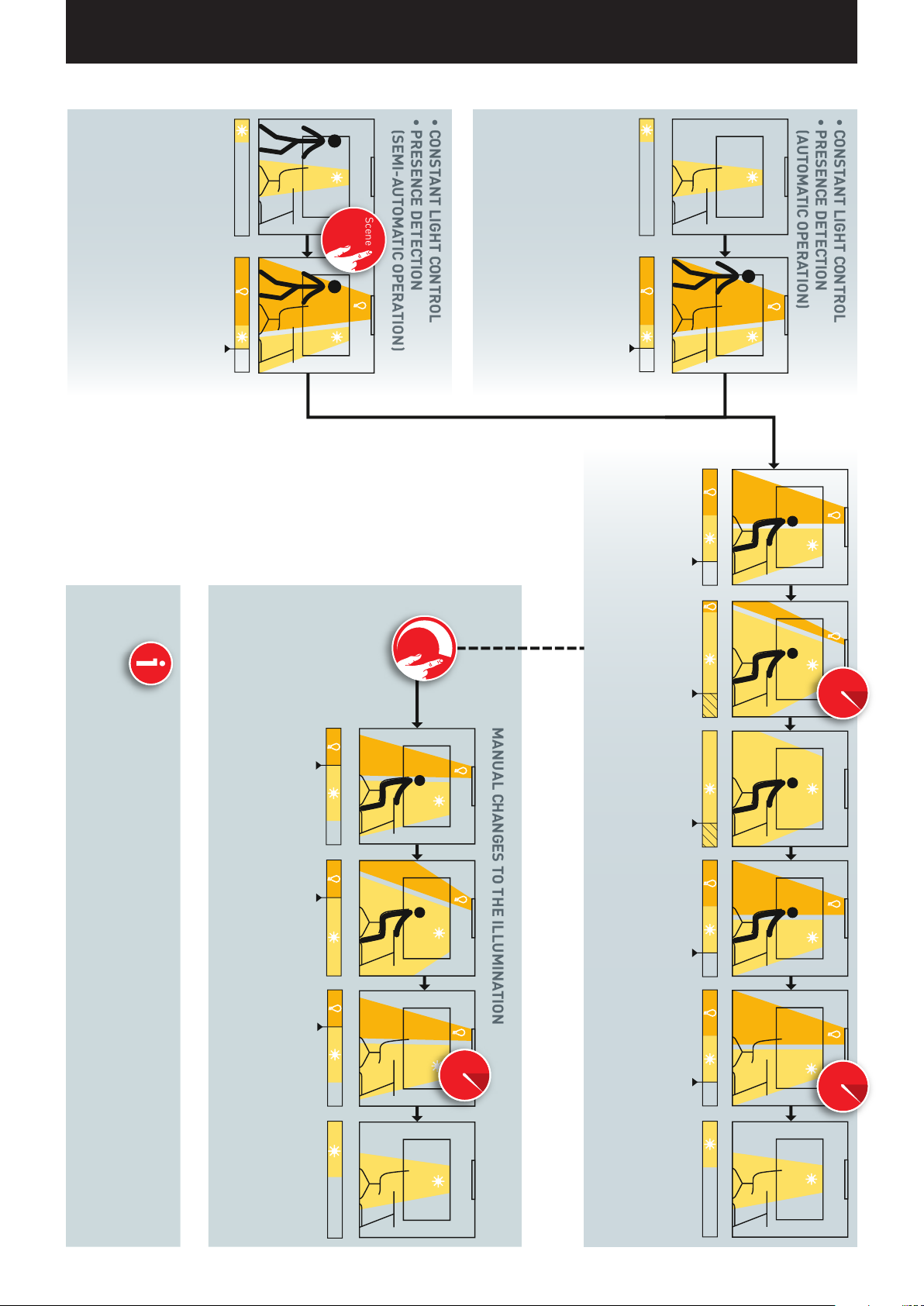
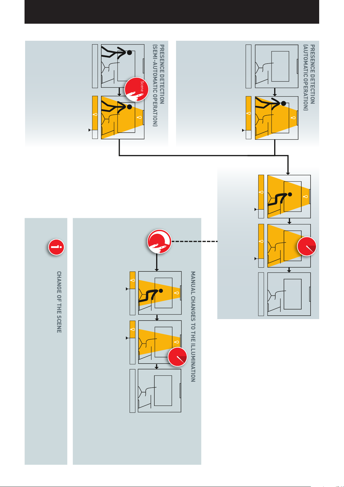
BEHAVIOUR IN OPERATION
The behaviour of the light control depends on how the system is being
switched on:
• Fully automatic presence detection
• Starting a scene with semi-automatic presence detection
• Starting a scene with light control
• Manual switching on of select or all luminaire groups
The decisive factor is, which controls (presence detection, light
control) are contained in the default scene. In the public Use Cases,
the respective most important scene is set as the default scene. In a
lot of cases, this is an automatic scene with fully automatic presence
detection and light control.
Additional information regarding this can be found in the chapter
“What is a Use Case? / Public Use Cases”.
On the following pages, the behaviour of the light control in the different situations is shown.
Page 15
INTRODUCTION / BEHAVIOUR OF LIGHT CONTROL / BEHAVIOUR IN DELIVERY CONDITION
Szene
i
Scene
i
• CONSTANT LIGHT CONTROL
• PRESENCE DETECTION
(AUTOMATIC OPERATION)
• CONSTANT LIGHT CONTROL
• PRESENCE DETECTION
(SEMI-AUTOMATIC OPERATION)
MANUAL CHANGES TO THE ILLUMINATION
room.
If the scene additionally contains constant light
control, the overall illumination (from daylight
and artificial light) is continuously being ad-
justed to the pre-set target value.
and artificial light) is continuously being ad-
tion with semi-automatic operation, the scene
is started with a push-button or with a tablet
and/or smart phone.
If the scene additionally contains constant light
control, the overall illumination (from daylight
If the default scene contains presence detec-
justed to the pre-set target value.
If the default scene contains presence detec-
tion with fully automatic operation, the lighting
starts with the default scene upon entering the
changed daylight.
The illumination ad-
justs itself to the
Page 15 / 77
this chapter).
of course, change as well (see other pages in
ADVANCED SETTINGS
Through advanced settings in the default
scene, a switching on again of the illumina-
tion upon dropping below the target value can
be prevented.
tion are retained.
CHANGE OF THE SCENE
If a change is made to a scene that contains
other operating modes (constant light control
and presence detection), the behaviour does,
In case of a manual intervention, the dim-
ming and switching of luminaire groups, the
constant light control is deactivated for these
luminaire groups. During the stay in the room,
the changed dimming levels of the illumina-
The presence detection remains maintained
even after a manual change of the illumi-
nation. Subsequent to a subsequent holding
time, it turns the illumination off after the
room has been left.
mination initially dims to a minimum. If the
overall illumination exceeds the target value
by 25 % for more than 5 minutes, the illumi-
nation turns off.
comes less, the illumi-
nation switches itself
on again and adjusts
to the target value.
the illumination turns off after the room has
been left.
In case of strong ingress of sunlight, the illu-
If the daylight be-
Subsequent to a subsequent holding time,
Page 16
INTRODUCTION / BEHAVIOUR OF LIGHT CONTROL / BEHAVIOUR IN DELIVERY CONDITION
Scene
i
Scene
i
PRESENCE DETECTION
(AUTOMATIC OPERATION)
PRESENCE DETECTION
(SEMI-AUTOMATIC OPERATION)
MANUAL CHANGES TO THE ILLUMINATION
CHANGE OF THE SCENE
If the default scene contains presence detec-
tion with semi-automatic operation, the scene
is started with a push-button or with a tablet
and/or smart phone.
with the default scene upon entering the room.
in the scene.
with fully automatic operation, the lighting starts
If the default scene contains presence detection
If somebody is pres-
ent, the illumination
remains at the dim-
ming level predefined
Page 16 / 77
detection), the behaviour does, of course, change as well (see other pages in this chapter).
Subsequent to a subsequent holding time,
the illumination turns off after the room has
been left.
Manual switching and
dimming of luminaire
groups is possible.
They remain main-
tained during the stay
If a change is made to a scene that contains other controls (constant light control and presence
in the room.
The presence detection remains maintained
even after a manual change of the illumination.
After a subsequent holding time, it turns the il-
lumination off after the room has been left.
Page 17
INTRODUCTION / BEHAVIOUR OF LIGHT CONTROL / BEHAVIOUR IN DELIVERY CONDITION
Szene
i
Scene
i
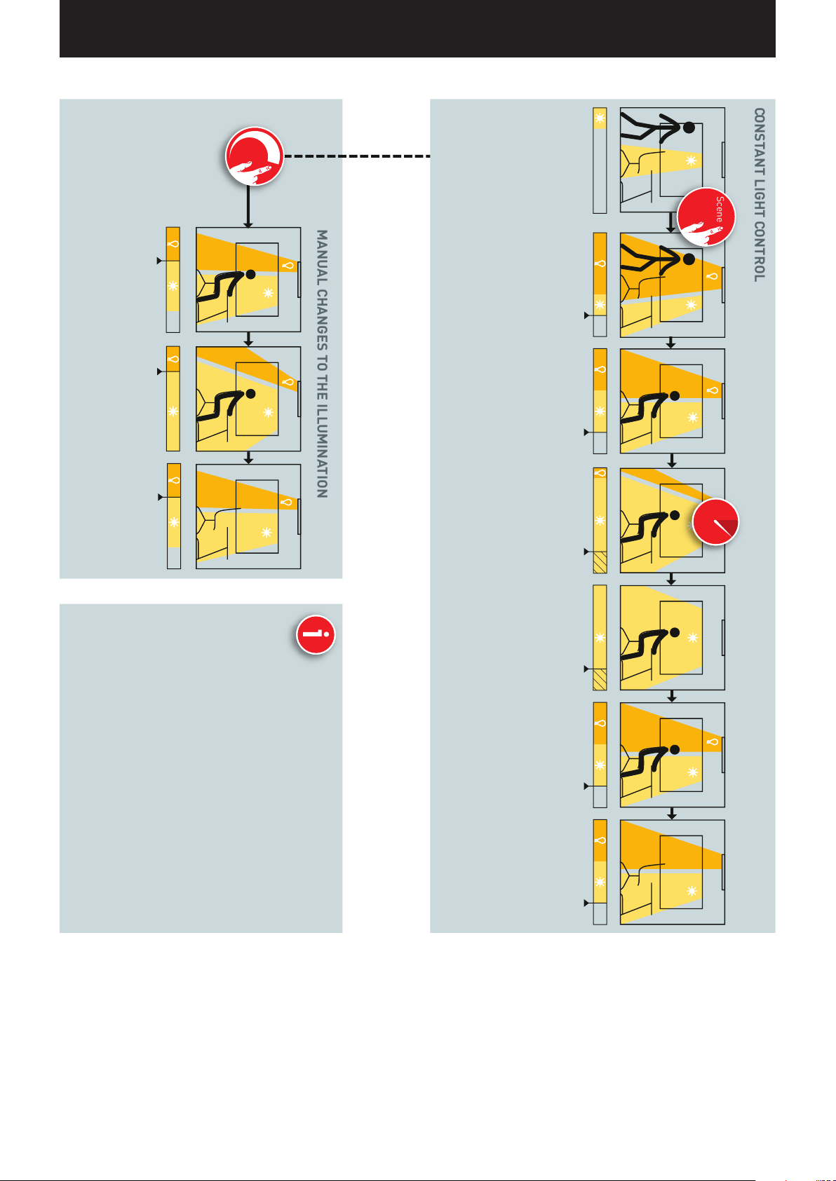
CONSTANT LIGHT CONTROL
MANUAL CHANGES TO THE ILLUMINATION
In case of a manual intervention, the dim-
ming and switching of luminaire groups, the
constant light control is deactivated for these
luminaire groups. During the stay in the room,
the changed dimming levels of the illumina-
tion are retained.
After leaving the
room, the illumina-
tion remains in the
last selected setting.
justed to the pre-set target value.
and artificial light) is continuously being ad-
nation turns off.
Upon entering the room, a scene is started with
a push-button or via tablet and/or smart phone.
If the scene exclusively contains constant light
control, the overall illumination (from daylight
The illumination
adjusts itself to the
changed daylight.
In case of strong ingress of sunlight, the illu-
mination initially dims to a minimum. If the
overall illumination exceeds the target value
by 25 % for more than 5 minutes, the illumi-
Page 17 / 77
ping below the target value can be prevented.
ADVANCED SETTINGS
Through advanced settings in the default scene, a
switching on again of the illumination upon drop-
well (see other pages in this chapter).
tection), the behaviour does, of course, change as
controls (constant light control and presence de-
CHANGE OF THE SCENE
If a change is made to a scene that contains other
If the daylight be-
comes less, the il-
lumination switches
itself on again and
adjusts to the target
value.
After leaving the
room, the illumi-
nation remains
switched on.
Page 18
INTRODUCTION / BEHAVIOUR OF LIGHT CONTROL / BEHAVIOUR IN DELIVERY CONDITION
i
MEM
AUSEIN EIN
i
MEM
OFFON ON
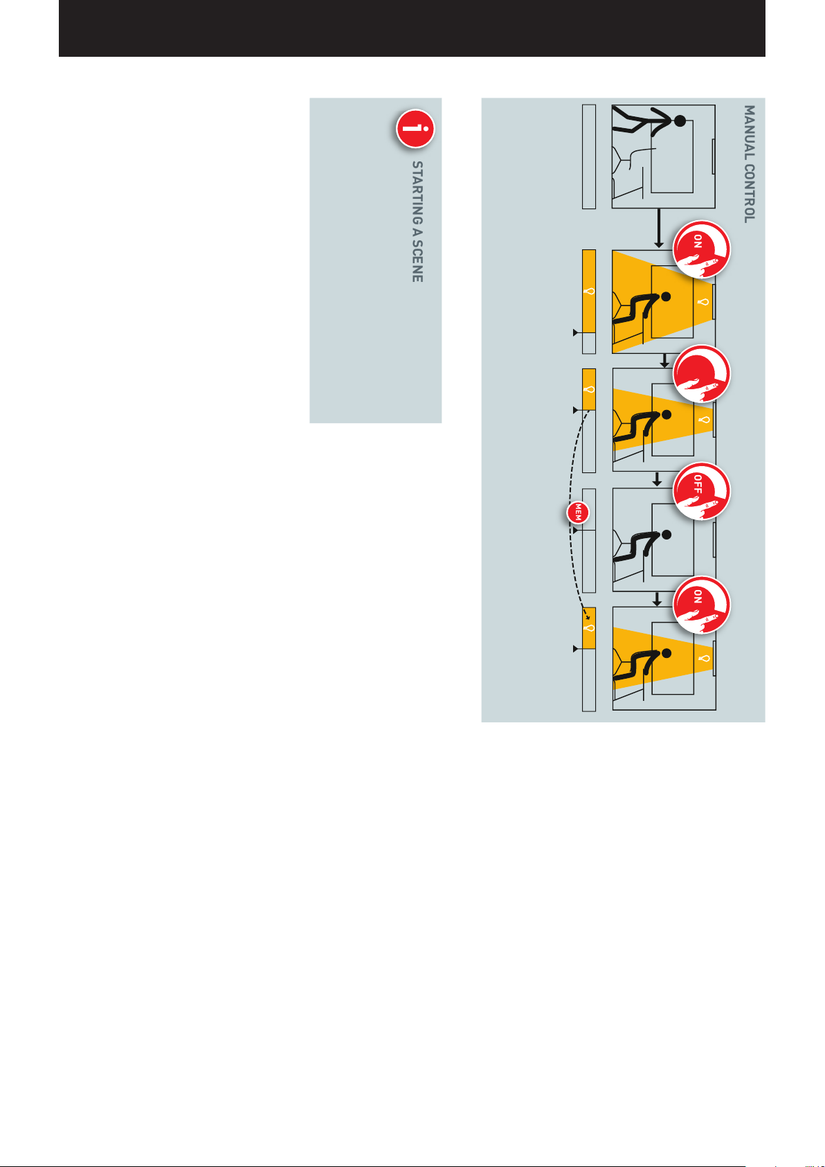
MANUAL CONTROL
STARTING A SCENE
tablet and/or smart phone, ...
Of course, scenes can also be started after man-
ually switching on the illumination. (see the other
pages of this chapter, depending on the control of
the scene)
As an alternative to the automatic and manu-
al starting of a scene, individual or all luminaire
groups can be switched with a push-button or via a
... dimmed, ...
Page 18 / 77
called.
value is being re-
… and switched off.
Upon switching back
on, the last dimming
Page 19
“LIVELINK INSTALL” APP / OVERVIEW Page 19 / 77
“LIVELINK INSTALL” APP
OVERVIEW
There are iOS-based and Android-based apps available that do not
differ in terms of functionality. There merely are minor deviations in
the screen presentation.
Shown in these instructions are screenshots of the iOS app. Any differences in the operation of the Android are pointed out as necessary.
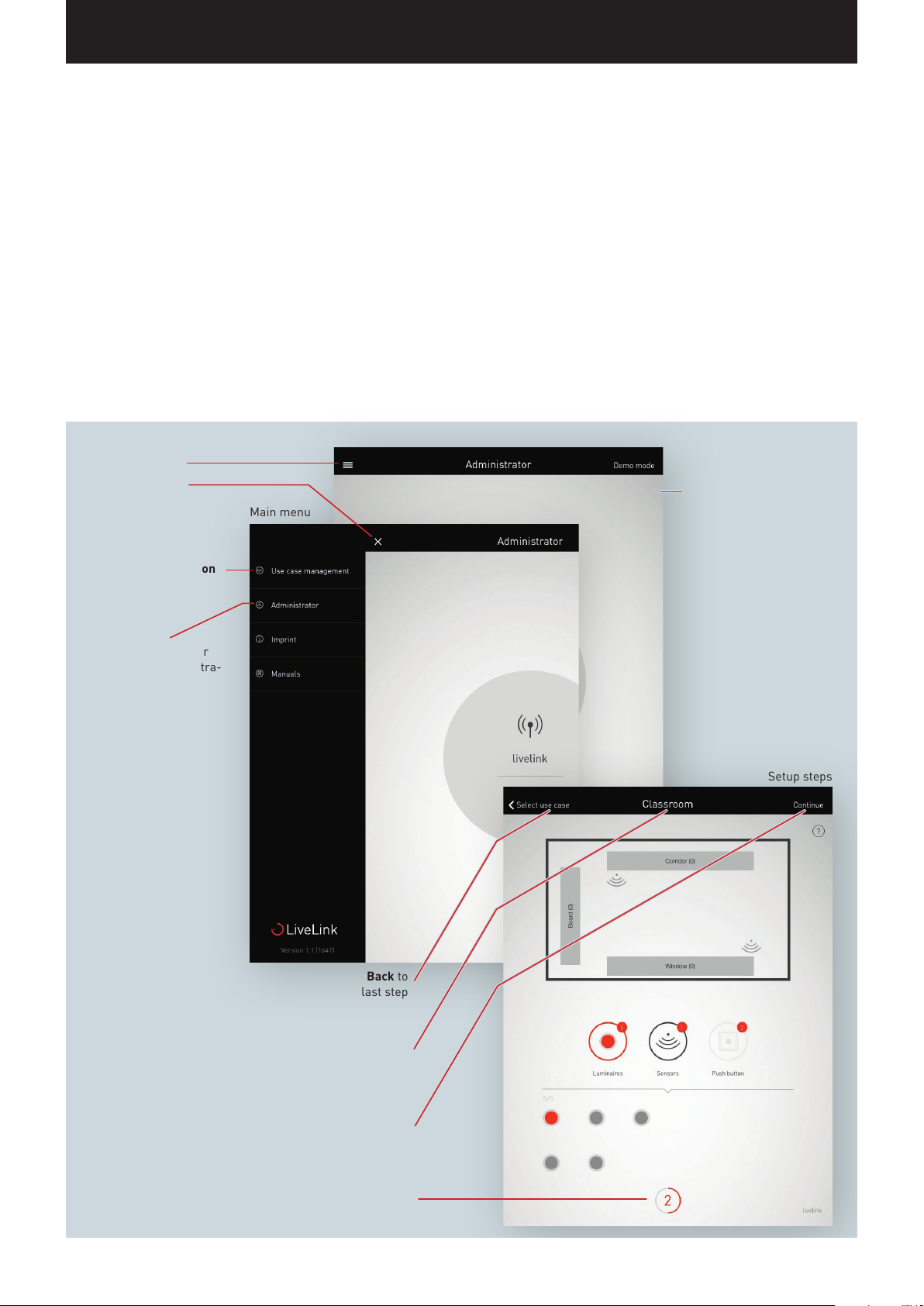
The following screenshots show the basic elements of the app operation that are available for a comfortable operation throughout the
Start screen
Open main menu
Close main menu
Main menu
Use Case administration
Administrator
Administrator menu for
the setup and administra-
tion of rooms
whole app. A repetitive description of these elements was omitted in
the remainder of these instructions.
Help
Back to
last step
Current
Setup step / current menu
Continue to next step /
Save and continue to next step
Show number and circuit
Progress of room setup
Setup steps
Page 20

“LIVELINK INSTALL” APP / WHAT IS A USE CASE? / PUBLIC USE CASES Page 20 / 77
WHAT IS A USE CASE?
Each LiveLink room is set up based on a Use Case. A Use Case is a
pre-configuration that simplifies the further setup of the room.
A Use Case defines:
• The number of luminaire groups (presentation of a schematic
matching the room type)
• The assignment between sensors and luminaire groups
• Scenes included in the delivery (which, of course, can be supplemented
by scenes you created on your own)
In addition to the placement of luminaire groups, a Use Case also
includes a pre-configuration of the sensors.
A Use Case constitutes the foundation of the room setup. If individualised
Use Cases are needed, these can be created in cooperation with the
TRILUX light planners and loaded for utilisation as “Private Use Cases”.
PUBLIC USE CASES
The public Use Cases are included in the delivery and can be updated in
the Use Case administration (see chapter “Use Case administration”).
The following Use Cases are going to be covered on the next pages.
Office Industry Education Shop & Retail Health & Care General
• Small Office
• Large Office
• Conference Room
After completion of the steps for commissioning, the scenes pre-set
in the Use Cases can be adjusted or additional ones added. You can,
for example, change the switch-off delays, switch from fully automatic
to semi-automatic operation, or change the dimming level.
The daylight-dependent control requires an initial calibration with the
help of an illuminometer (see chapter “Administrating scenes”).
• Manufacturing
Hall, simple
• Manufacturing
Hall, expanded
• Classroom
• Individual Sports
Hall
• Retail • Patients' room • Corridor
• Universal
(See chapter “Universal Use Case”)
Page 21
“LIVELINK INSTALL” APP / WHAT IS A USE CASE? / PUBLIC USE CASES Page 21 / 77
Traffic route 1
Traffic route 2
Work 1
Work 3
Work 2
SV1
SV4
SA1
SV2
SV5
SA2
SV3
SV6
SA3
Bed 3
Bed 2
Work
Additional Meeting
S1
Traffic route 1
Traffic route 2
Work 1
Work 4
Work 3
Work 6
Work 2
Work 5
SV1
SV4
SA1
SA4
SV2
SV5
SA2
SA5
SV3
SV6
SA3
SA6
Corridor (+ Centre)
Window
Board
S1
S2
Bed 3
Bed 2
Bed 1
S1
S1
S2
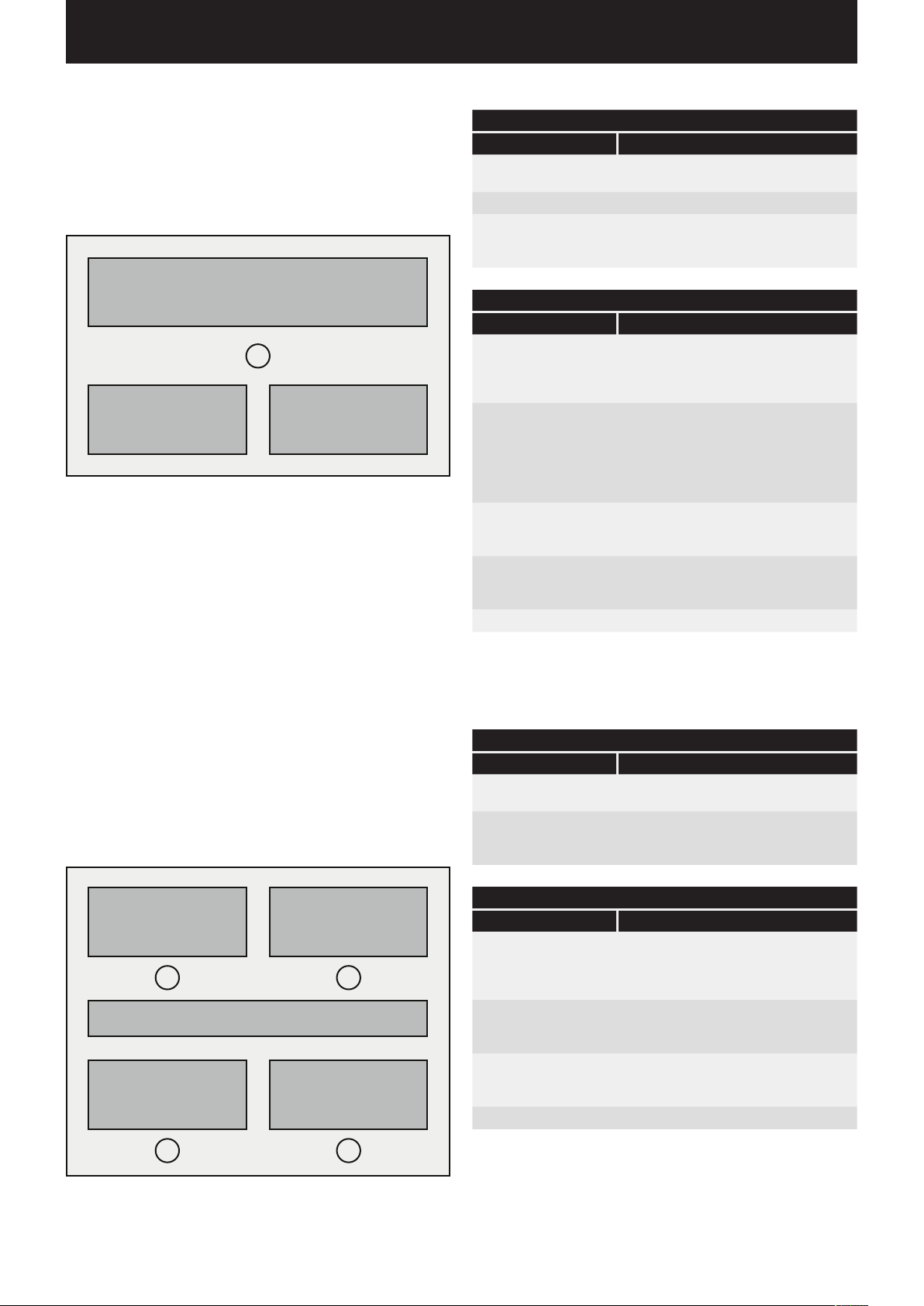
Use Case “Small Office”
In the Use Case “Small Office”, the luminaire groups “Work”, “Meeting”, and “Additional” are applied. In addition, there is one sensor
that is responsible for daylight-dependent light control as well as
presence detection.
Work
S1
Additional Meeting
Presetting of the luminaire groups
Group of luminaires Function
Work • Presence detection
• Daylight-dependent control
Meeting • Presence detection
Additional
e. g. for accentuating
lighting
Presets of the scenes
Scene Function
Automatic • 5 minutes switch-off delay
Meeting • Constant dimming levels
Service • Constant dimming level for all groups
Night lighting • Constant dimming level
Off • All groups off
• Presence detection
• Fully automatic operation for the group
“Work”
• Daylight-dependent control active
for all groups:
• Work 50 %
• Meeting 100 %
• Additional 20 %
• 10 minutes switch-off delay
at 100 %
• 10 minutes switch-off delay
for all groups at 20 %
• no automatic switch-off
Use Case “Large Office”
In the Use Case “Large Office”, the luminaire groups “Traffic Route”, “Work
2”, “Work 3”, “Work 4”, and “Additional” are applied. In addition, there are
four sensors that are responsible for daylight-dependent light control as
well as presence detection. This is done separately for each group.
Work 1
S1
Work 3
S3
Work 2
S2
Additional
Work 4
S4
Presetting of the luminaire groups
Group of luminaires Function
Work 1-4 • Presence detection
Additional
e. g. for accentuating
lighting
Presets of the scenes
Scene Function
Automatic
Service • Constant dimming level for all groups
Night lighting • Constant dimming level
Off • All groups off
• Daylight-dependent control
• Presence detection
• 5 minutes switch-off delay,
fully automatic operation
• Daylight control active via sensors S1-4,
each separately
at 100 %
• 10 minutes switch-off delay
for all groups at 20 %
• no automatic switch-off
Page 22
“LIVELINK INSTALL” APP / WHAT IS A USE CASE? / PUBLIC USE CASES Page 22 / 77
Work
Additional Meeting
S1
Additional
Work 3
Work 1
Work 4
Work 2
S1
S3
S2
S4
Traffic route 1
Traffic route 2
Work 1
Work 4
Work 3
Work 6
Work 2
Work 5
SV1
SV4
SA1
SA4
SV2
SV5
SA2
SA5
SV3
SV6
SA3
SA6
Corridor (+ Centre)
Window
Board
S1
S2
HallS1 S2
Bed 3
Bed 2
Bed 1
S1
S1
S4
S7
S2
S5
S8
Use Case “Conference Room”
In the Use Case “Conference Room”, the luminaire groups “Meeting”,
“Presentation”, and “Additional” are applied. In addition, there is one
sensor that is responsible for daylight-dependent light control as well
as presence detection.
Meeting PresentationS1
Additional
Presetting of the luminaire groups
Group of luminaires Function
Meeting Presence detection
Daylight-dependent control
Presentation Presence detection
Daylight-dependent control
Additional
e. g. for accentuating
lighting
Presets of the scenes
Scene Function
Automatic • 10 minutes switch-off delay
Projection • Constant dimming levels
Lecture • Constant dimming levels
Service
Night lighting • Constant dimming level
Off • All groups off
Presence detection
for all groups, fully automatic operation
• Daylight-dependent control active
for the following groups:
• Meeting 20%
• Additional 20 %
• Presentation 0 %
• 10 minutes switch-off delay
for the following groups:
• Meeting 50%
• Additional 20 %
• Presentation 100%
• 10 minutes switch-off delay
• Constant dimming level for all groups at 100 %
• 10 minutes switch-off delay
for all groups at 20 %
• no automatic switch-off
Page 23
“LIVELINK INSTALL” APP / WHAT IS A USE CASE? / PUBLIC USE CASES Page 23 / 77
Work
Additional Meeting
S1
Additional
Work 3
Work 1
Work 4
Work 2
S1
S3
S2
S4
Additional
Meeting PresentationS1
Traffic route 1
Traffic route 2
Work 1
Work 4
Work 3
Work 6
Work 2
Work 5
SV1
SV4
SA1
SA4
SV2
SV5
SA2
SA5
SV3
SV6
SA3
SA6
Corridor (+ Centre)
Window
Board
S1
S2
HallS1 S2
Accent
Shop Window
Cash Register
Shop
S1
S2 S3
Bed 3
Bed 2
Bed 1
S1
S1
S4
S7
S2
S5
S8
Bed 3
Bed 2
Bed 1
Table
Room
S1
S2
Bathroom
Corridor
Use Case “Manufacturing Hall, simple”
In the Use Case “Manufacturing Hall, simple”, the luminaire groups
“Traffic Route”, “Work 1”, “Work 2”, and “Work 3” are applied. In
addition, there are three sensors that are responsible for daylightdependent light control (SA1 – 3) and three sensors that are responsible
for presence detection (SV1 – 3).
Traffic route
SV1
SA1
Work 1 Work 3Work 2
SV2
SA2
SV3
SA3
Presetting of the luminaire groups
Group of luminaires Function
Traffic route • Presence detection
via the sensors SV1-3
Work 1-3 • Manual switching
Presets of the scenes
Scene Function
Automatic • Daylight control active for groups
Service • Constant dimming level for all groups
Night lighting • Constant dimming level
Off • All groups off
• Daylight-dependent control via
sensor SA1-3
“Work 1-3”
• Presence detection
for group “Traffic Route”,
Fully automatic operation with
10 minutes switch-off delay
at 100 %
• 20 minutes switch-off delay
for all groups at 20 %
• no automatic switch-off
Use Case “Manufacturing Hall, expanded”
In the Use Case “Manufacturing Hall, expanded”, the luminaire
groups “Traffic Route 1”, “Traffic Route 2”, “Work 1”, “Work 2”, “Work
3”, “Work 4”, “Work 5”, and “Work 6” are applied. In addition, there
are six sensors that are responsible for daylight-dependent light
control (SA1 – 6) and six sensors that are responsible for presence
detection (SV1 – 6).
SV1
SV4
SA1
Work 1
Traffic route 1
SV2
Traffic route 2
SV5
SA2
Work 2
SV3
SV6
SA3
Work 3
Presetting of the luminaire groups
Group of luminaires Function
Traffic route 1-2 • Presence detection
Work 1-6 • Manual switching
Presets of the scenes
Scene Function
Automatic • Daylight-dependent control active via
Service • Constant dimming level for all groups
Night lighting • Constant dimming level
Off • All groups off
• Daylight-dependent control
sensors SA1-6 (per group)
• Presence detection with 10 minutes
switch-off delay (sensor SV1-6),
fully automatic operation
at 100 %
• 20 minutes switch-off delay
for all groups at 20 %
• no automatic switch-off
SA4
Work 4
SA5
Work 5
SA6
Work 6
Page 24
“LIVELINK INSTALL” APP / WHAT IS A USE CASE? / PUBLIC USE CASES Page 24 / 77
Traffic route 1
Traffic route 2
Work 1
Work 4
Work 3
Work 6
Work 2
Work 5
SV1
SV4
SA1
SA4
SV2
SV5
SA2
SA5
SV3
SV6
SA3
SA6
Bed 3
Bed 2
Bed 1
Table
Room
S1
S2
Bathroom
Corridor
S1
S2 S3
G3
G2
G1
S1
S2
S3
Traffic route 1
Traffic route 2
Work 1
Work 4
Work 3
Work 6
Work 2
Work 5
SV1
SV4
SA1
SA4
SV2
SV5
SA2
SA5
SV3
SV6
SA3
SA6
Corridor (+ Centre)
Window
Board
S1
S2
Bed 3
Bed 2
Bed 1
Table
Room
S1
S2
Bathroom
Corridor
S1
S2 S3
G3
G6
G9
G2
G5
G8
G1
G4
G7
S1
S4
S7
S2
S5
S8
S3
S6
S9
Use Case “Classroom”
In the Use Case “Classroom”, the luminaire groups “Board”, “Window”,
and “Corridor (+ Centre)” are applied. In addition, there are two sensors that are responsible for daylight-dependent light control as well
as the presence detection per group.
Corridor (+ Centre)
Board
S1
Window
S2
Presetting of the luminaire groups
Group of luminaires Function
Board • Presence detection
Window • Presence detection
• Daylight-dependent control
Corridor (+ Centre) • Presence detection
• Daylight-dependent control
Presets of the scenes
Scene Function
Automatic
Projection
Service • Constant dimming level for all groups
Night lighting • Constant dimming level for
Off • All groups off
• 10 minutes switch-off delay,
semi- automatic operation for all groups
• Individualised daylight-dependent
control for the groups “Window” (S1)
and “Corridor” (S2)
• Constant dimming levels for the following
groups:
• Board 0 %
• Window 20 %
• Corridor 20 %
• 5 minutes switch-off delay
at 100 %
• 10 minutes switch-off delay
all groups at 20 %
• no automatic switch-off
Use Case “Individual Sports Hall”
In the Use Case “Individual Sports Hall”, the luminaire group “Hall” is
applied. In addition, there is a sensor (S1) that is responsible for the
daylight-dependent light control as well as the presence detection,
and a sensor (S2) only for presence detection.
HallS1 S2
Presetting of the luminaire groups
Group of luminaires Function
Hall • Presence detection,
Presets of the scenes
Scene Function
Automatic standard
Automatic bright
Service • Constant dimming level for all groups
Night lighting • Constant dimming level for all groups
Off • All groups off
• Daylight-dependent control
• 15 minutes switch-off delay,
fully automatic operation
• Daylight-dependent control active with
85 % of the system's output
• 15 minutes switch-off delay,
fully automatic operation
• Daylight-dependent control active with
100% of the system's output
at 100 %
• 10 minutes switch-off delay,
semi-automatic operation
at 20%
• no automatic switch-off
Page 25
“LIVELINK INSTALL” APP / WHAT IS A USE CASE? / PUBLIC USE CASES Page 25 / 77
Traffic route 1
Traffic route 2
Work 1
Work 4
Work 3
Work 6
Work 2
Work 5
SV1
SV4
SA1
SA4
SV2
SV5
SA2
SA5
SV3
SV6
SA3
SA6
Corridor (+ Centre)
Window
Board
S1
S2
HallS1 S2
Bed 3
Bed 2
Bed 1
Table
Room
S1
S2
Bathroom
Corridor
S1
S2 S3
G3
G6
G9
G2
G5
G8
G1
G4
G7
S1
S4
S7
S2
S5
S8
S3
S6
S9
Use Case “Retail”
In the Use Case “Retail”, the luminaire groups “Shop Window”, “Cash
Register”, “Shop”, and “Accent” are applied. In addition, there are
three sensors that are responsible for daylight-dependent light
control per group
S1 S2 S3
Shop Window
.
Cash Register
Accent
Shop
Presetting of the luminaire groups
Group of luminaires Function
Shop Window • Manual operation
Cash Register • Manual operation
• Daylight-dependent control
Shop • Manual operation
Accent • Manual operation
Presets of the scenes
Scene Function
Automatic • Individualised daylight-depending
Service • Constant dimming level for all groups
Night • Constant dimming level
Off • All groups off
• Daylight-dependent control
• Group “Accent” set to 100 %
• no automatic switch-off
• 20 minutes switch-off delay
• no automatic switch-off
controls of the groups “Cash Register”
(S2) and “Shop” (S3)
at 100 %
for all groups at 20 %
Use Case “Patient Room”
In the Use Case “Patient Room”, the luminaire groups “Bathroom”,
“Room”, “Table”, “Bed 1”, “Bed 2”, “Bed 3”, and “Bathroom” [sic] are
applied. In addition, there are two sensors, one for daylight-dependent
light control and presence detection (S1), and one only for presence
detection in the bathroom (S2).
Bed 3
Bed 2
Bed 1
Bathroom
S1
Room
S2
Presetting of the luminaire groups
Group of lumi-
naires
Table
Bed 1-3 • Presence detection
Room • Presence detection
Table • Presence detection
Bathroom • Presence detection
Presets of the scenes
Scene Function
Automatic • Presence detection for beds, room, and table
Examination • Constant dimming level
Service
Off • All groups off
Function
• Daylight-dependent control
• Daylight-dependent control
in semi-automatic operation
• Presence detection for the bathroom
in fully automatic operation
• Daylight-dependent control active
for all groups at 100%
• no automatic switch-off
• Constant dimming level for all groups at 100 %
• 10 minutes switch-off delay
Page 26
“LIVELINK INSTALL” APP / WHAT IS A USE CASE? / PRIVATE USE CASES Page 26 / 77
Bed 3
Bed 2
Bed 1
Table
Room
S1
S2
Bathroom
Bed 3
Bed 2
Bed 1
Table
Room
S1
S2
Bathroom
Corridor
S1
S2 S3
Use Case “Corridor”
In the Use Case “Corridor”, the luminaire group “Corridor” is applied.
In addition, there are three sensors that are responsible for daylightdependent light control as well as presence detection. Sensor 1-3
control the presence detection, sensor 1 the daylight-dependent control.
Corridor
S1 S2 S3
PRIVATE USE CASES
Project-related, Use Cases are always created in cooperation with the
TRILUX light planners.
The finished Use Cases are then made available in the customer account
of the myTRILUX portal (see chapter “Administrating Use Cases”).
Presetting of the luminaire groups
Group of luminaires Function
Corridor • Presence detection
• Daylight-dependent control
Presets of the scenes
Scene Function
Automatic
Service • Constant dimming level for all groups
Night lighting • Constant dimming level
Off • All groups off
• 5 minutes switch-off delay,
fully automatic operation
• Daylight-dependent control active
(via sensor 1)
at 100 %
• 10 minutes switch-off delay
for all groups at 20 %
• no automatic switch-off
UNIVERSAL USE CASE
In addition to the application specific Use Cases (public & private), the
public Use Case “Universal” is also available.
In the Use Case “Universal”, nine freely assignable luminaire groups
“G1-G9” are applied. In addition, there are nine freely assignable
sensor spots that are responsible for daylight-dependent light control
as well as presence detection.
S1
S4
S7
S2
S5
S8
S3
S6
S9
G1
G4
G7
G2
G5
G8
Presets of the scenes
Scene Function
ON • All groups at 100 %
OFF • All groups off
Additional scenes must be mandatorily created manually.
G3
G6
G9
Page 27
“LIVELINK INSTALL” APP / USE CASE ADMINISTRATION Page 27 / 77
USE CASE ADMINISTRATION
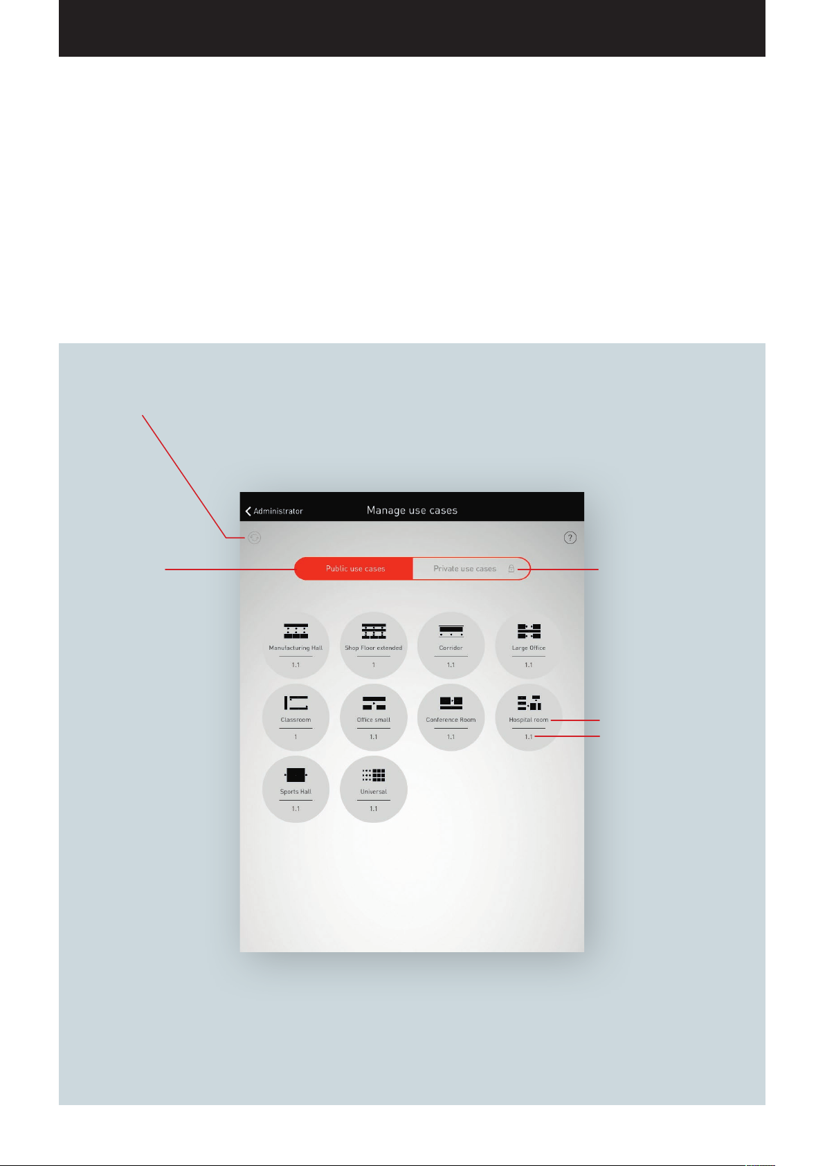
In this view, Use Cases are administrated.
The public Use Cases can be updated and deleted. Private Use Cases
can be downloaded from the myTRILUX Portal and administrated.
Updating
Updating the public Use Cases from
the TRILUX portal.
Public Use Cases
All available Use Cases are
listed.
After a long tap, there is the
option to delete select Use
Cases.
Private Use Cases
Access to the TRILUX portal,
from which private Use Cases
can be loaded at this point.
Use Case name
Version number
Page 28
“LIVELINK INSTALL” APP / USE CASE ADMINISTRATION Page 28 / 77
ADMINISTRATING PUBLIC USE CASES
Updating Use Cases
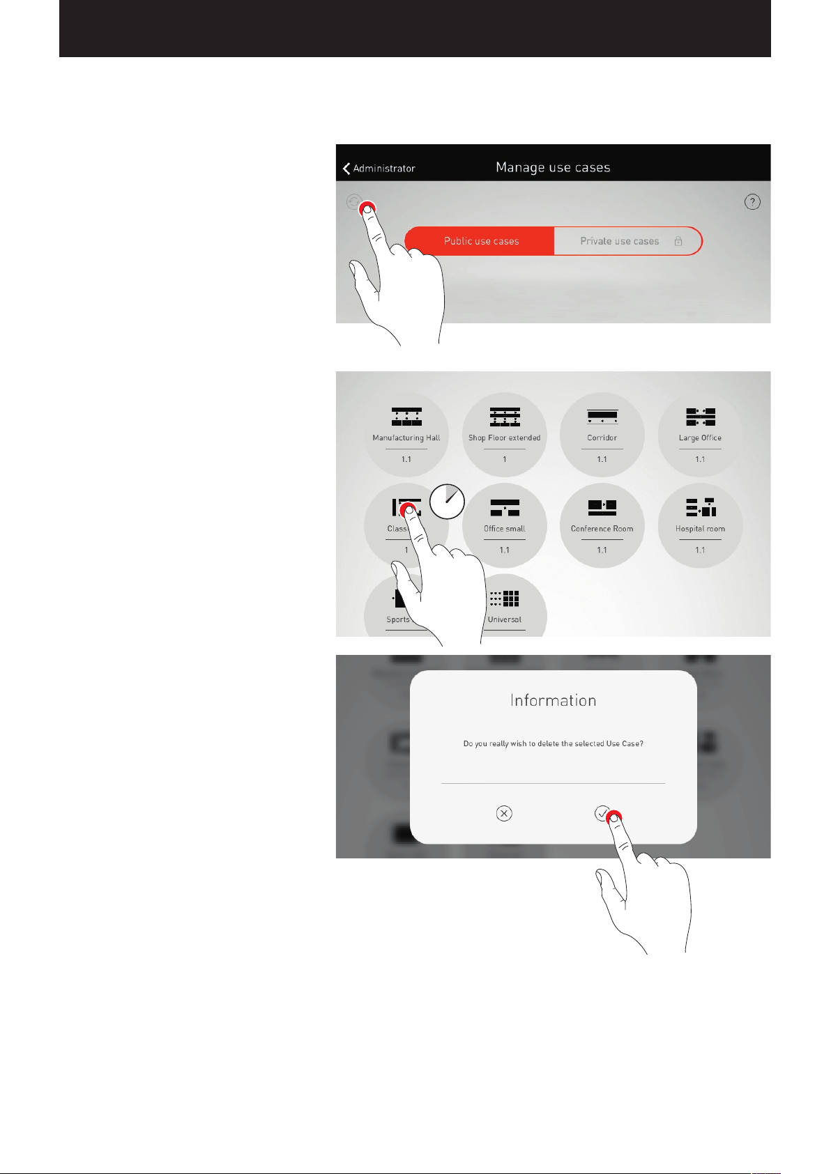
The menu “Administrating Use Cases” starts with a
listing of all public Use Cases that are available in
the app for the configuration of rooms.
The Use Cases listed here are updated by tapping
the refresh button
Caution: Updating requires an Internet connection
since the data is retrieved from a TRILUX server via
the Internet! Where applicable, the WLAN must be
switched or a mobile data connection must be utilised.
Deleting Use Cases
After an update, Use Cases may be listed multiple
times with different version numbers. Superfluous
Use Cases can be deleted: After a long tap on the
Use Case presentation, the Use case can be deleted.
.
Page 29
“LIVELINK INSTALL” APP / USE CASE ADMINISTRATION Page 29 / 77
ADMINISTRATING PRIVATE USE CASES
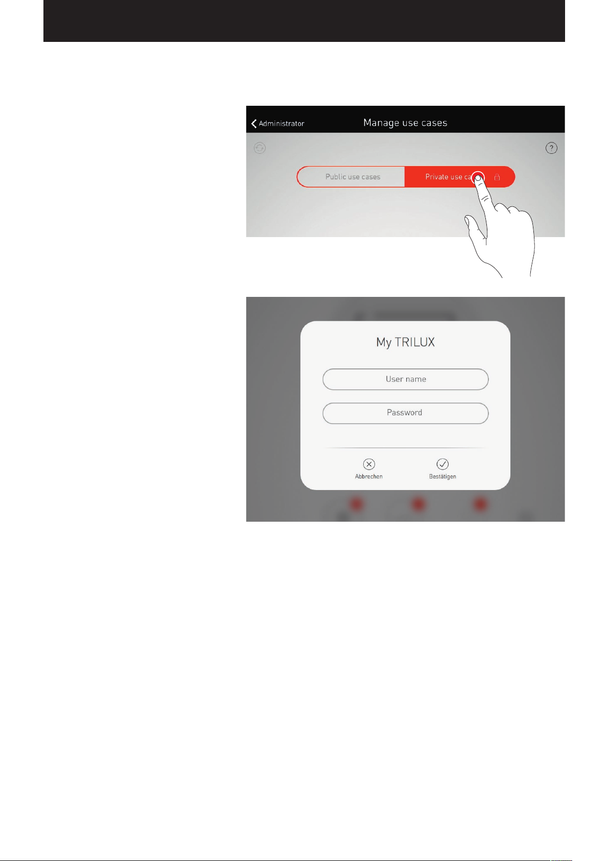
Selecting private Use Cases
With a tap on “Private Use Cases”, the view switches
to “Administrating private Use Cases”.
Administrating private Use Cases
The input screen allows for access to the customer
account at the myTRILUX portal. Here, the customised
Use Cases created are available.
Caution: The access to the myTRILUX portal
requires an Internet connection. Where applicable,
the WLAN must be switched or a mobile data
connection must be utilised.
Page 30
“LIVELINK INSTALL” APP / ROOM ADMINISTRATION Page 30 / 77
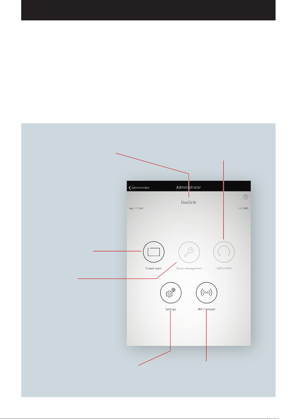
ROOM ADMINISTRATION
The Administrator menu includes the most important functions of the
setup app: the setup and/or administration of rooms as well as various
settings. The menu is protected with a separate administrator password.
Room name
All settings in this administrator menu refer to
this room.
Create room
Guides through the individual steps of the
initial setup of a new room.
If this room was already created, its existing
configuration can be deleted at this point and
a new room setup can be started.
Room administration
After the initial setup, select setup steps
can be changed here:
• Use Case
• Assignment
• Administrate push-buttons
• Room name
• Administrate scenes
Light control
Access to the light control; function-
ality like user app.
Settings
Allows for various additional
settings.
WLAN / Hotspot
Connecting the control device
with an existing network infra-
structure.
Page 31
“LIVELINK INSTALL” APP / ROOM ADMINISTRATION / ROOM SETUP Page 31 / 77
ROOM SETUP
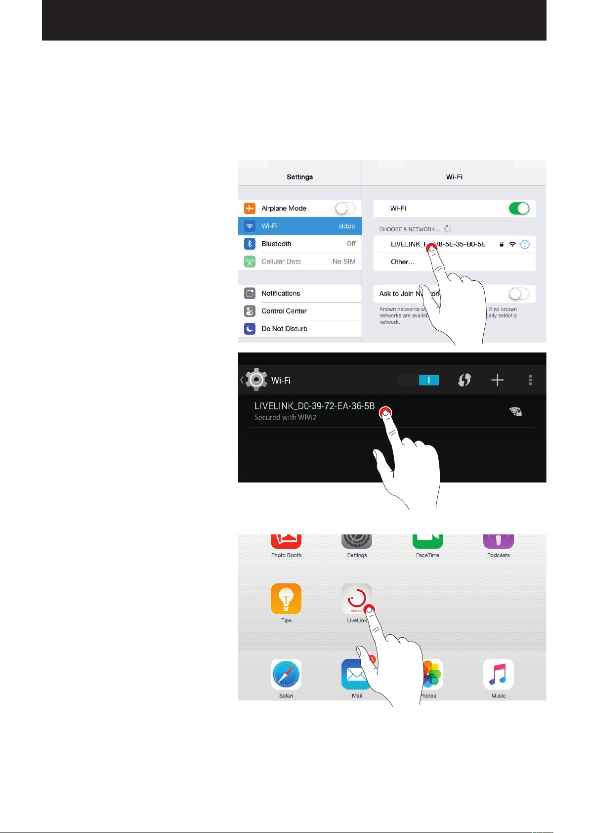
Upon the initial setup, a connection to the system is established
and prepared for the further configuration.
Initial connection to the WLAN
The tablet is connected directly to the WLAN that is
made available by the LiveLink control device.
Start the app
For the configuration of LiveLink, the “LiveLink”
app is utilised which is available for iOS tablets at
the Apple App Store, and for Android tablets at the
Google Play Store.
Page 32
“LIVELINK INSTALL” APP / ROOM ADMINISTRATION / ROOM SETUP Page 32 / 77
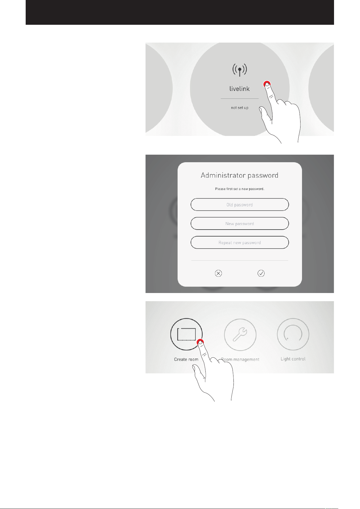
Select room
The app starts in the administrator menu and
searches for existing LiveLink rooms.
Here, the not-yet set up room can be selected.
Initially, the room designation is a factory setting
which can later be changed in the “Room name” menu.
In delivery condition, the administrator password is:
livelink
Change administrator password
On the next screen, a new administrator password
is specified.
Start room configuration
A tap on “Create room” starts the creation of a room
and leads to the first step “Select Use Case”.
Page 33
“LIVELINK INSTALL” APP / ROOM ADMINISTRATION / ROOM SETUP: USE CASE Page 33 / 77
ROOM SETUP: USE CASE
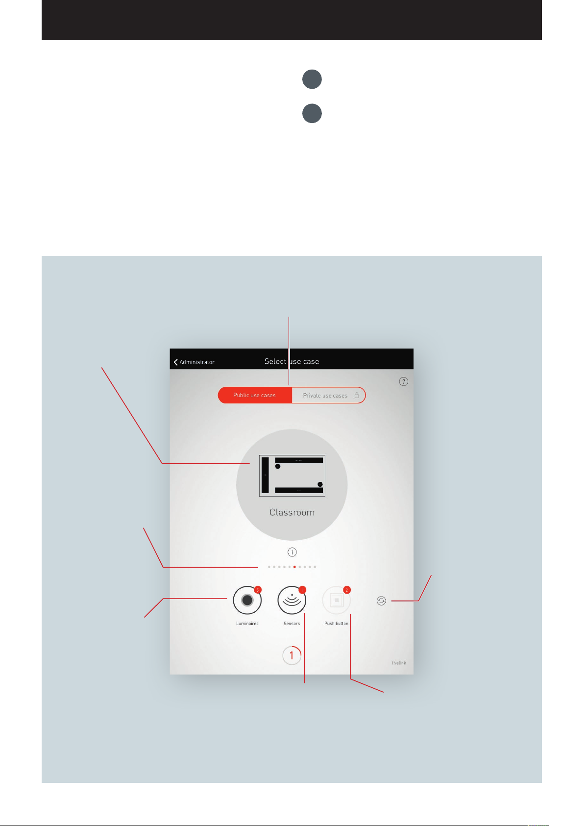
In this view, a matching Use Case is selected and assigned to the room.
Represented in a simplified room schematic - a Use Case does
contain a placement of luminaire groups and sensors as well as
preconfigured light scenes.
For typical room situations, multiple “public Use Cases” are available.
For special applications, individualised “private Use Cases” can be
called up.
The view does, furthermore, provide an overview of the connected
luminaires, sensors, and push-buttons as well as the option to identify these devices.
Choice between public and private Use Cases.
Public Use Cases contain a pre-configuration for typical building situa-
Designation and schematic
of the selected Use Case.
The Use Case can be selected via swiping. A tap on
this schematic confirms the
selection and leads to the
next step.
tions. Private Use Cases can be created in cooperation with TRILUX light
planners and can subsequently be called up from the myTRILUX portal.
1.
Identifying luminaires and sensors
Select and confirm Use Case
2.
The dots serve for navigating
through the Use Cases. One
dot corresponds to one Use
Case. The currently selected
Use Case is displayed in white.
The number indicates the
number of luminaires
connected. After tapping this
icon, the luminaires blink for
identification. While this is
happening, the icon is shown
in red. The identification is
ended by tapping again.
The number indicates the number of sensors
connected. After tapping this icon, the status
lights of the sensors light up for identification.
While this is happening, the icon is shown
in red. The identification is ended by tapping
again.
After tapping the refresh
button, a choice of “Start
new search run” and
“Search for new devices” is
available.
A status display indicates an
active search.
Caution: A “search run”
impedes the functionality of
the system; see explanation
on the following pages.
The number indicates the number of
push-button couplers connected plus the
allowed push-button on the control device.
Push-buttons connected to a coupler are not
included in the count at this point.
Page 34
“LIVELINK INSTALL” APP / ROOM ADMINISTRATION / ROOM SETUP: USE CASE Page 34 / 77
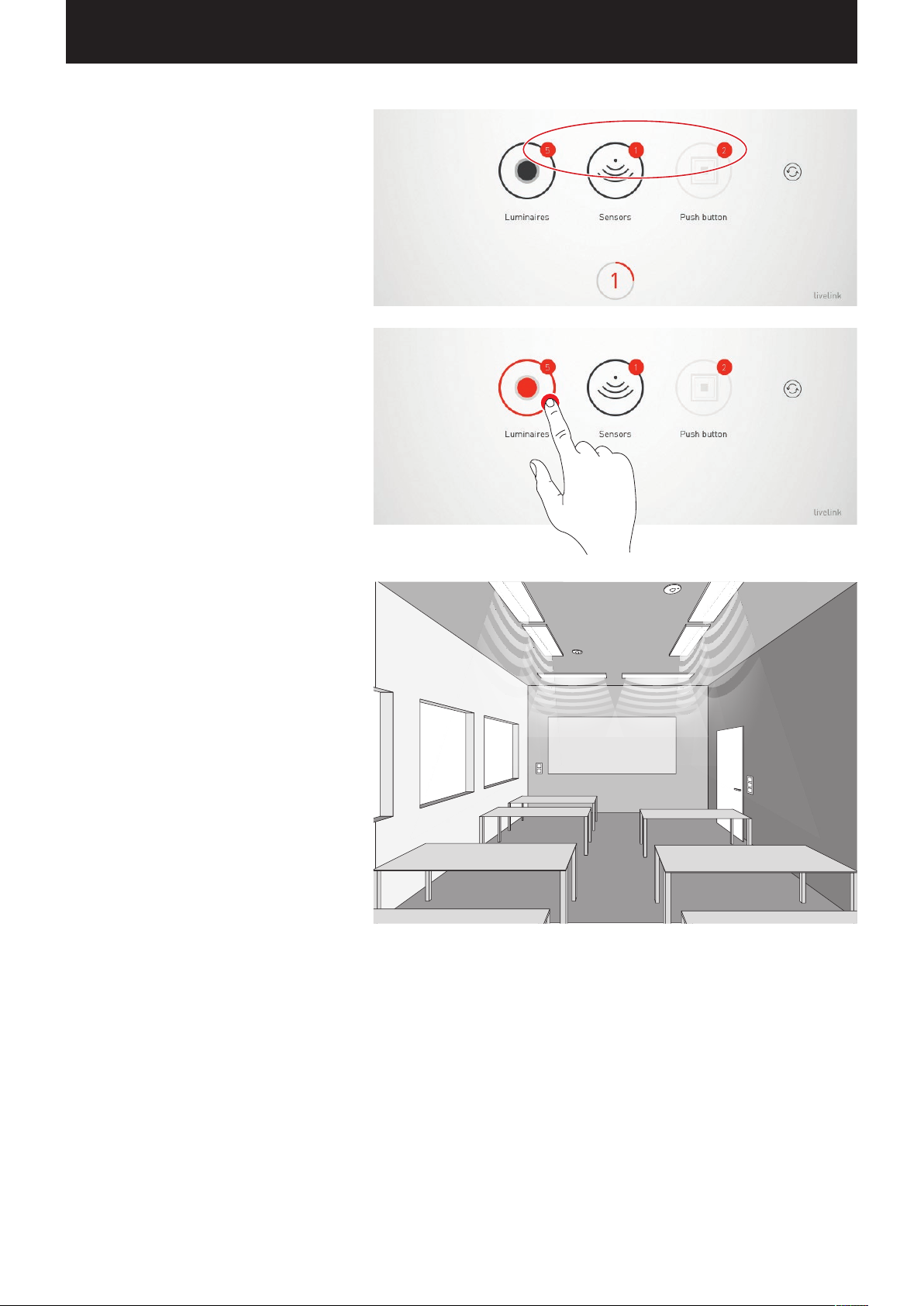
Listing connected devices
Numbers on the icons of the device groups “Luminaires”, “Sensors”, and “Push-buttons” indicate
the respective number of devices connected. A
push-button coupler is counted only once in this,
even though multiple push-buttons may be
connected there.
Identifying luminaires/sensors
When selecting the drive group “Luminaires” or
“Sensors”, the identification is started: The respective
icon is shown in red; the registered luminaires and/
or the status lights of the sensors start to blink.
Tapping the icon again ends the identification.
Page 35
“LIVELINK INSTALL” APP / ROOM ADMINISTRATION / ROOM SETUP: USE CASE Page 35 / 77
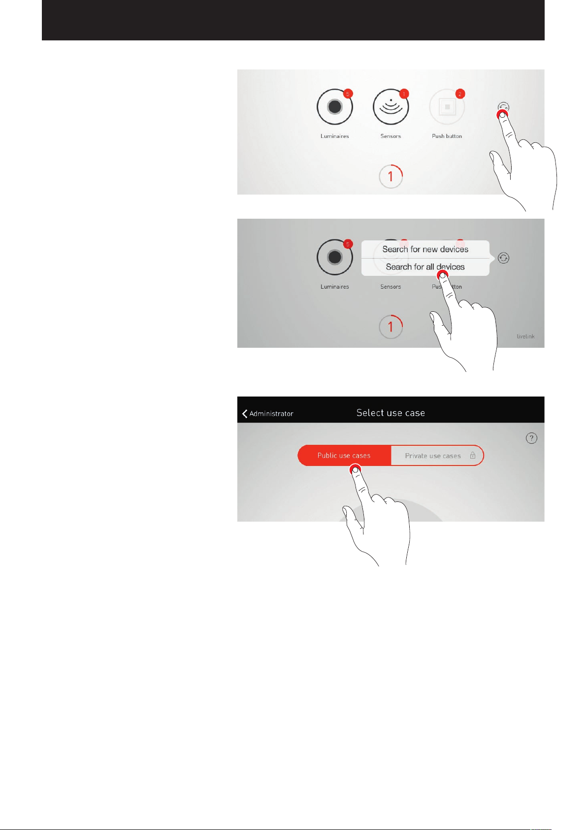
New search run / search for devices
If the search run upon commissioning did not
find all devices or if work is being performed on
the
installation in parallel, the search run and/or a
search for devices can be started again.
With a tap on the refresh button, a choice between a
new search run and a search for devices is available
• “Start new search run” once again search all
connected DALI participants and addresses all
devices anew. This is necessary if a previous
search run was incomplete or incorrect, for
example if - despite correct installation - not all
devices were found.
Caution: A renewed search run impedes the
functionality of the system. Due to the readdressing of the devices, the assignment needs to
be performed once again.
• “Search for new devices” finds devices that were
installed subsequently. This search run is significantly faster and does not lead to a change of the
existing configuration.
Public / private Use Cases
Initially, the corresponding Use Case collection is
selected by tapping on “Public Use Cases” or
“Private Use Cases”.
Additional information regarding this can be found
in the chapter “Use Case administration”.
Page 36
“LIVELINK INSTALL” APP / ROOM ADMINISTRATION / ROOM SETUP: USE CASE Page 36 / 77
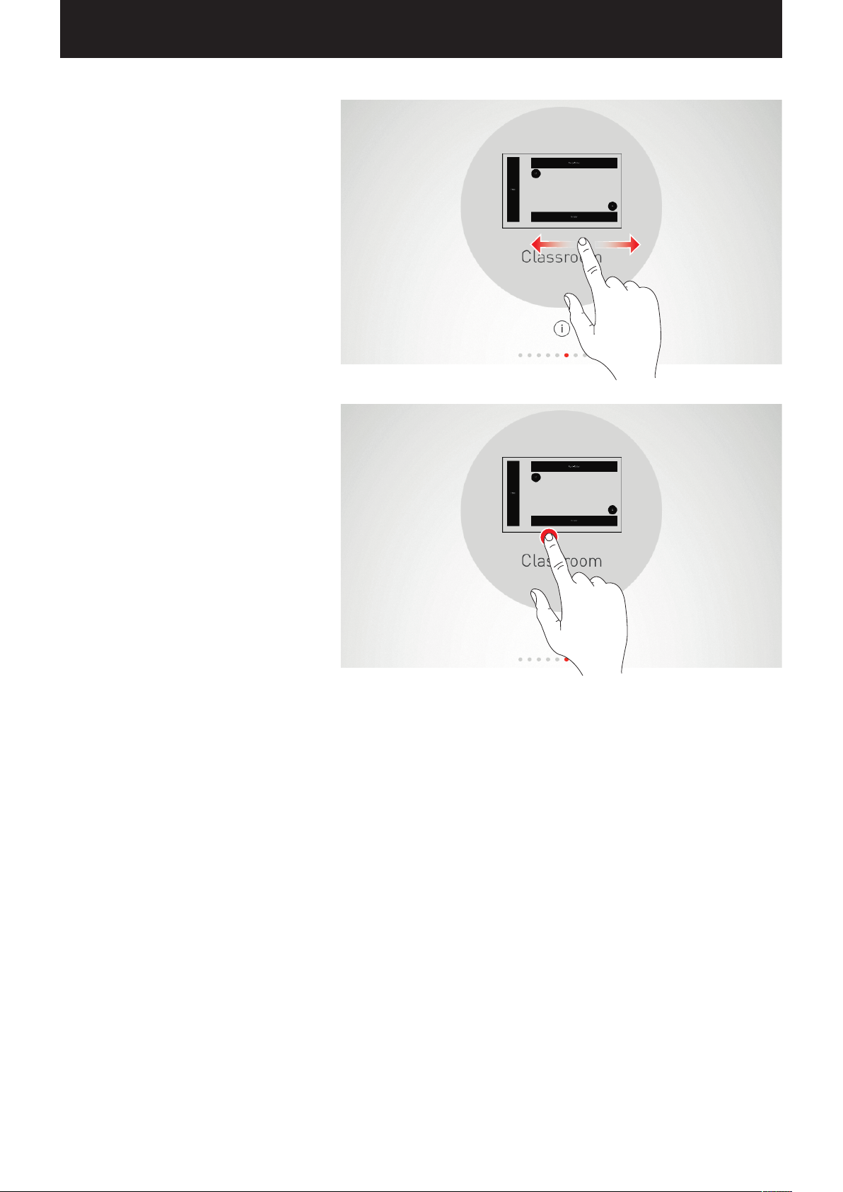
Selecting a Use Case
A matching Use Case is selected by swiping. A
rough schematic and the designation help in the
correct selection, wherein the schematic does not
have to fit the room situation in all details.
Confirming the selection
The selection is confirmed by tapping on the Use
Case and this configuration step is completed.
Page 37
“LIVELINK INSTALL” APP / ROOM ADMINISTRATION / ROOM SETUP: ASSIGNMENT Page 37 / 77
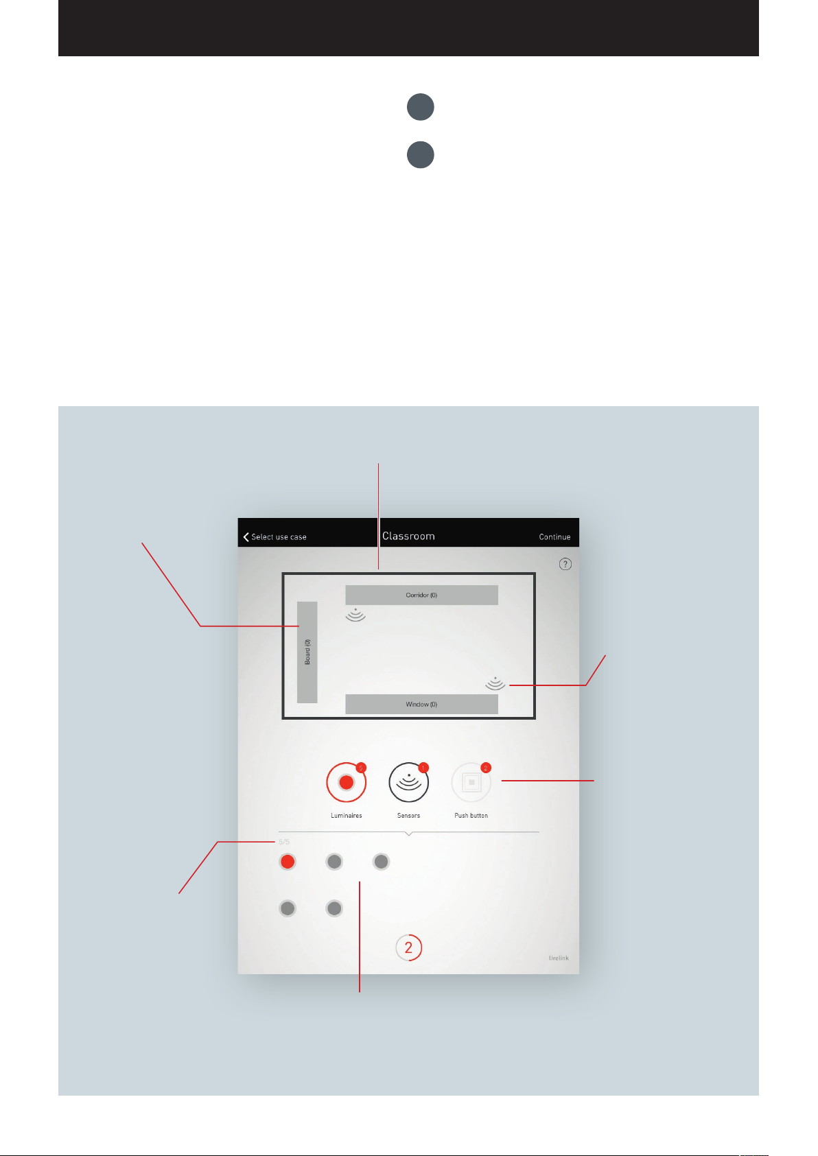
1.
ROOM SETUP: ASSIGNMENT
Group assignment of luminaires
In this view, the luminaires and sensors are assigned.
The individual luminaires and sensors can be identified and
assigned
A simplified schematic serves for orientation in the room and
provides for a comfortable assignment of the devices this way. The
number and positions of the luminaire groups and sensors origi
nate from the Use Case. The schematic cannot be modified but can
be utilised in a custom fashion. As such, not all luminaire groups
and sensor locations have to be utilised, for example.
to the luminaire groups and/or sensor locations.
Predefined luminaire
groups are included in each
room. The available luminaires can be assigned via
drag and drop. The number
at the right edge indicates
how many luminaires are in
the group.
-
The room schematic shows all luminaire
groups and sensor locations.
2.
Sensor assignment
Overview of the luminaires
and/or sensors already assigned in comparison to those
available.
Predefined sensor The available sensors can be assigned
via drag and drop.
Subsequent to a long tap,
additional functions can be
reached.
Switching between the
assignment of luminaires and
sensors. The respective active
are is shown in red.
Additionally, the number of
push-button couplers (plus
push-button on the control
device) available is displayed
for informational purposes.
The push-button assignment
is performed in a later step
Symbolic depiction of the available luminaires and/or sensors. As soon as a device is
selected, it is displayed in colour and can then
be assigned.
Page 38
“LIVELINK INSTALL” APP / ROOM ADMINISTRATION / ROOM SETUP: ASSIGNMENT Page 38 / 77
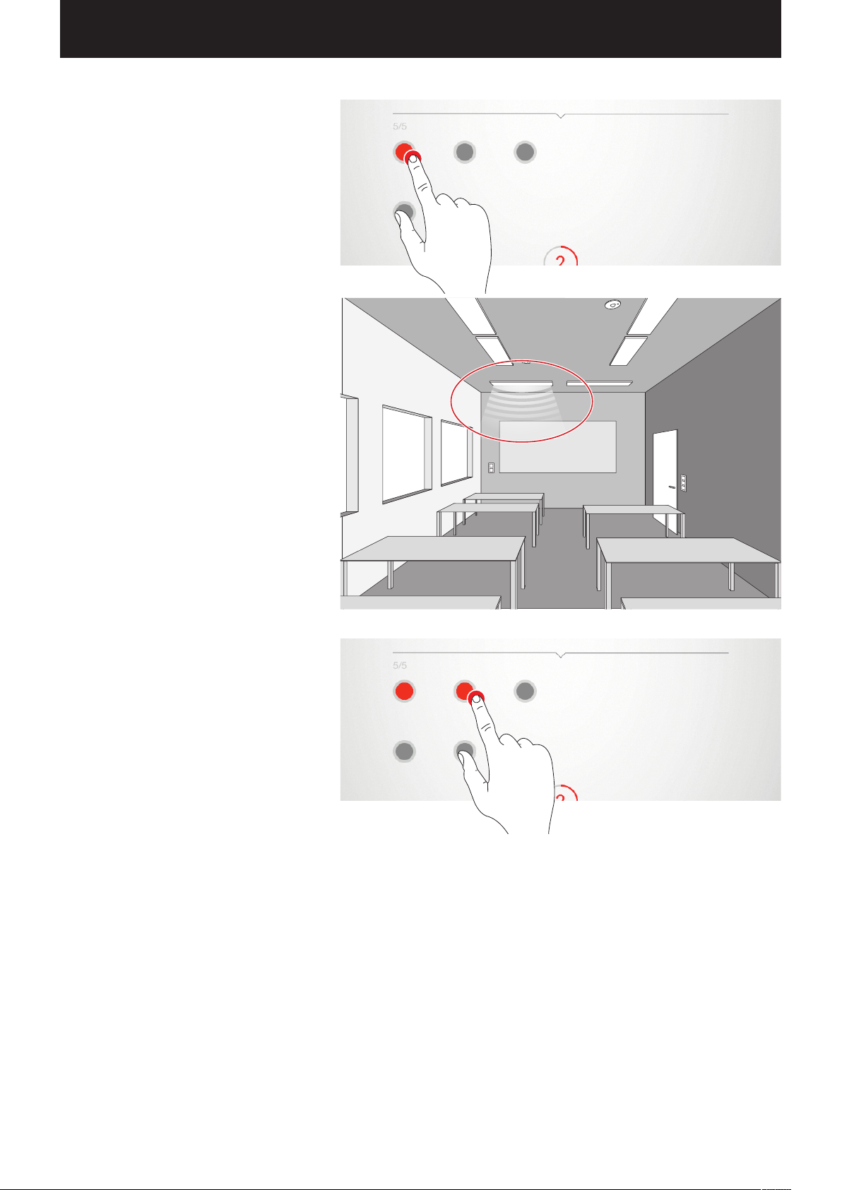
Selecting luminaires
Each dot in the lower area of this view represents
a luminaire. The luminaire is selected by tapping
a dot. The dot is shown bright and the luminaire
blinks for identification.
Multiple selection
Multiple luminaires can be selected one after
another in order to assign them collectively in the
next step.
Page 39
“LIVELINK INSTALL” APP / ROOM ADMINISTRATION / ROOM SETUP: ASSIGNMENT Page 39 / 77
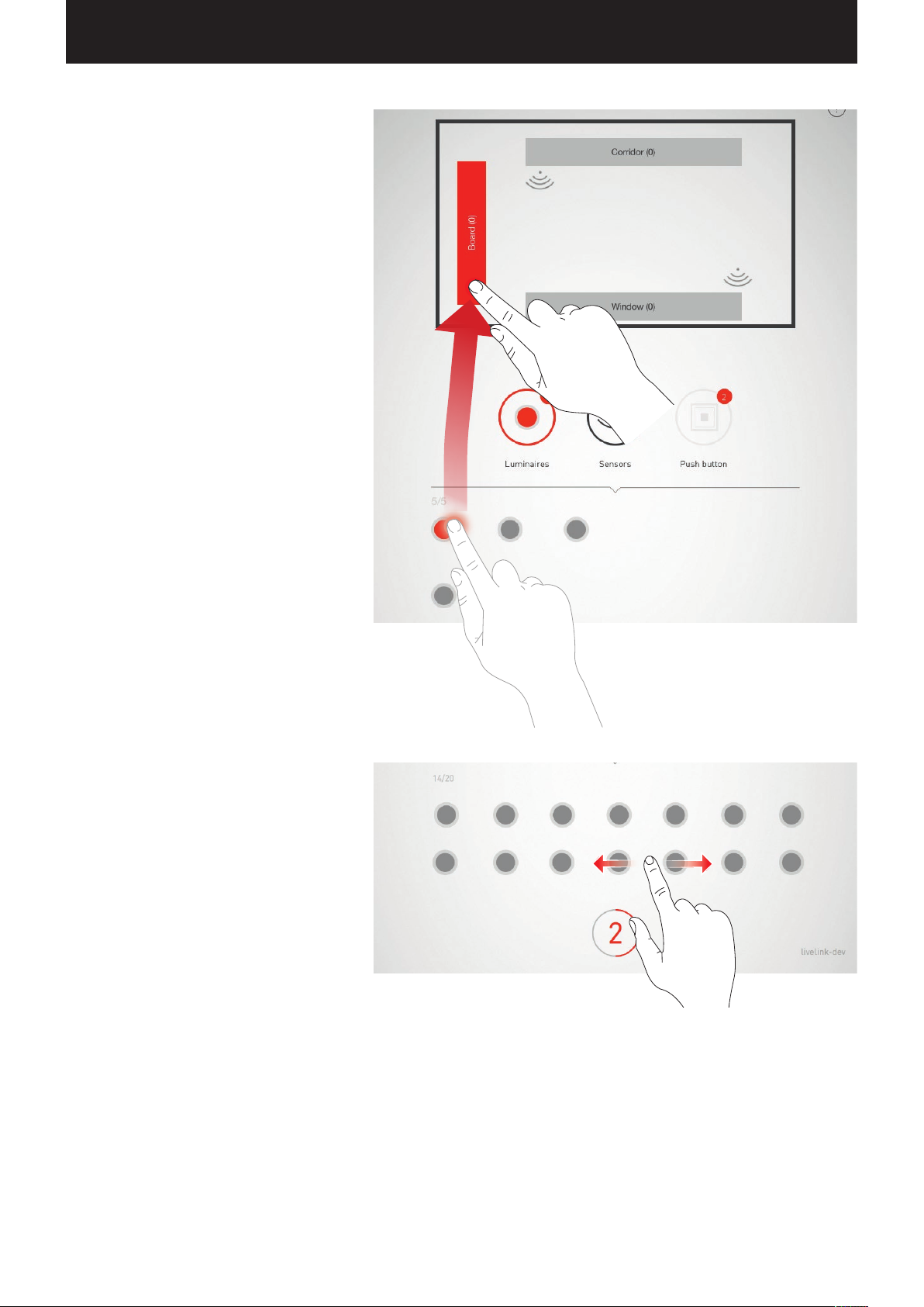
Assigning luminaires
The selected luminaires can now be pushed to a
luminaire group at top. If multiple luminaires were
selected, any one luminaire can be pushed in order
to assign the whole selection.
The dots that symbolise the luminaires are no
longer shown after the assignment.
Navigation in case of more than 12 luminaires
If more luminaires are available, the luminaire
selection is navigated by swiping through the pages.
Page 40
“LIVELINK INSTALL” APP / ROOM ADMINISTRATION / ROOM SETUP: ASSIGNMENT Page 40 / 77
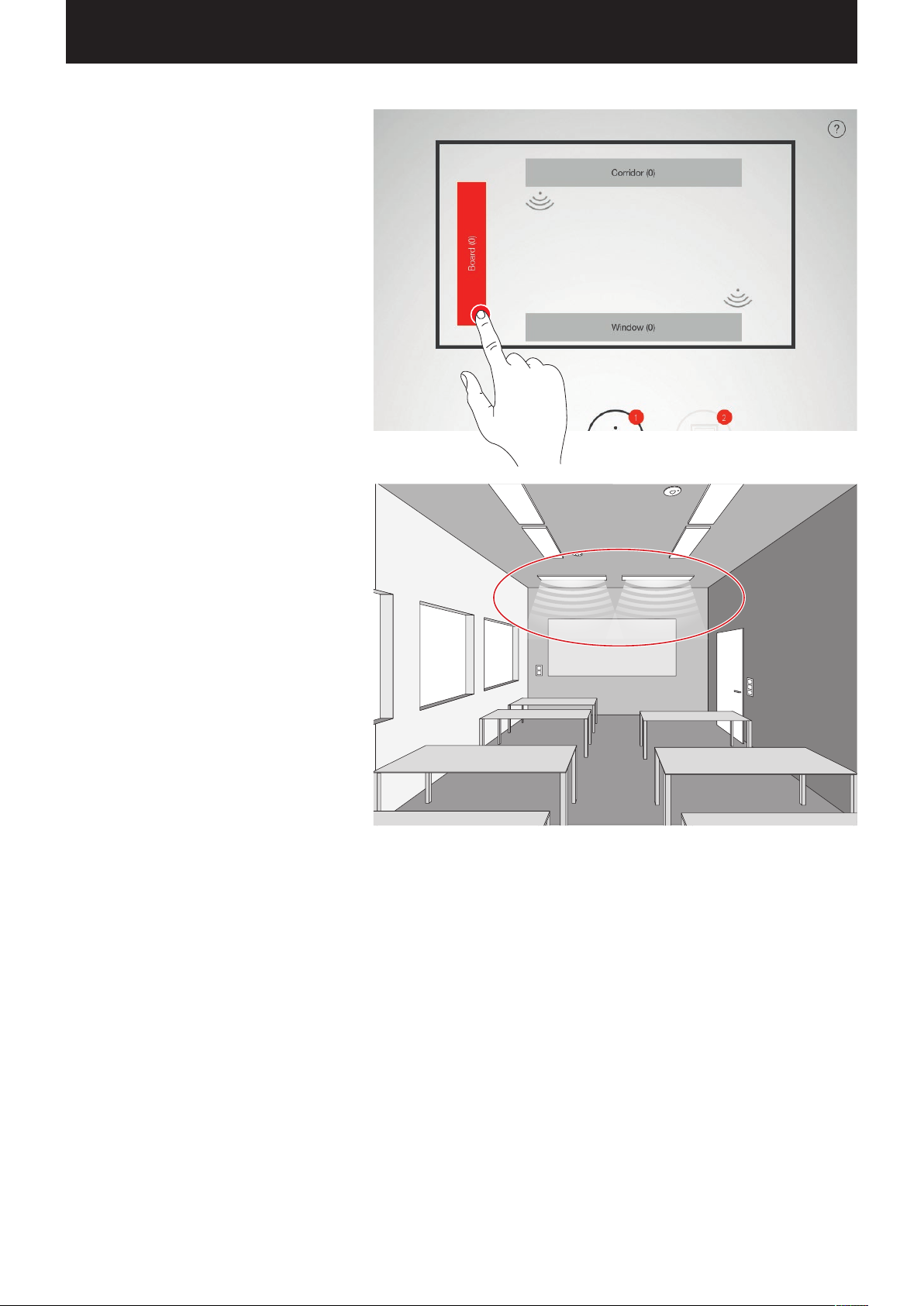
Checking the assignment
The number of luminaires already assigned can
be read on the symbols of the luminaire groups. In
addition, it is shown in the bottom area of the view
how many luminaires overall are available and how
many have not yet been assigned.
A group is selected by tapping on it. All corresponding
luminaires blink.
Page 41
“LIVELINK INSTALL” APP / ROOM ADMINISTRATION / ROOM SETUP: ASSIGNMENT Page 41 / 77
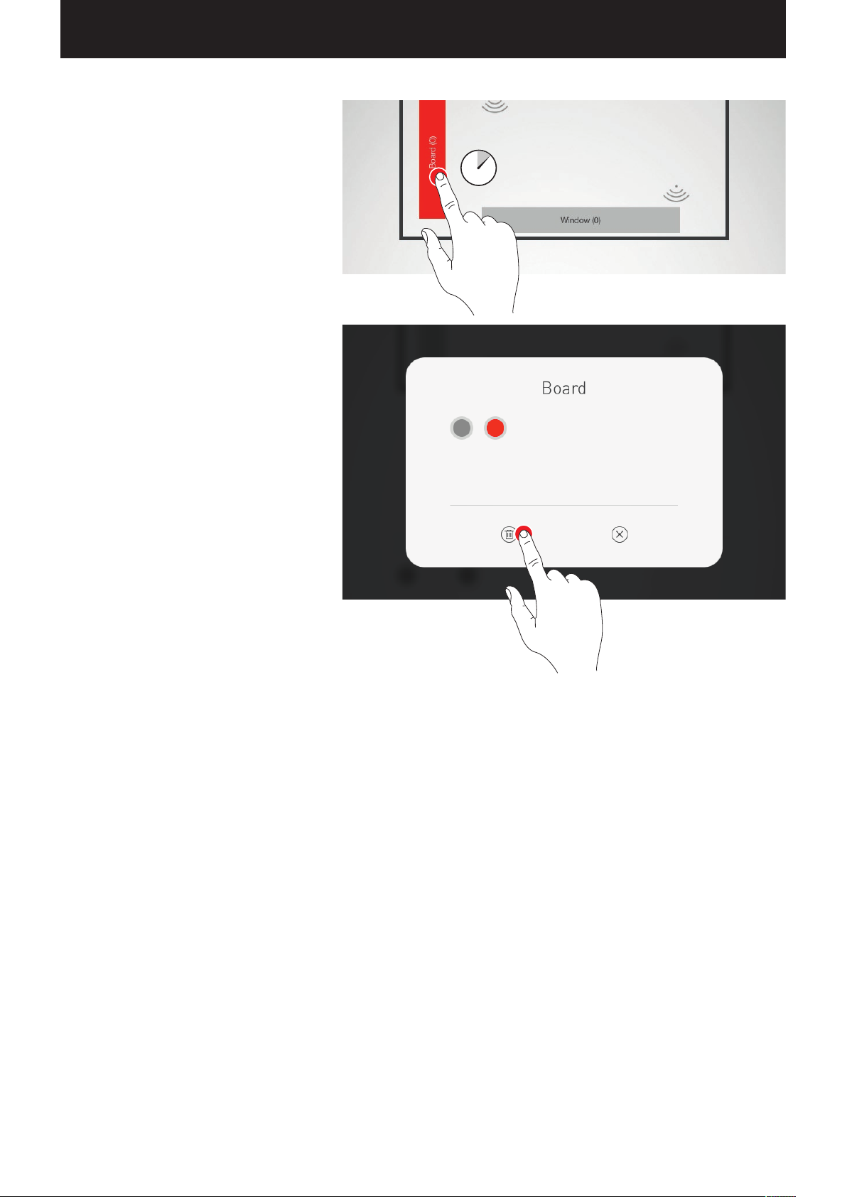
Removing luminaires from a group
A long tap opens a window that shows all luminaires
that have been assigned to this group.
luminaires can be identified by tapping them and
can be deleted by subsequently tapping the delete
button.
The individual
Concluding the luminaire assignment
Little by little, additional luminaires can be
assigned. In this, not all luminaires need to be
assigned and not all luminaire groups need to be
used.
Page 42
“LIVELINK INSTALL” APP / ROOM ADMINISTRATION / ROOM SETUP: ASSIGNMENT Page 42 / 77
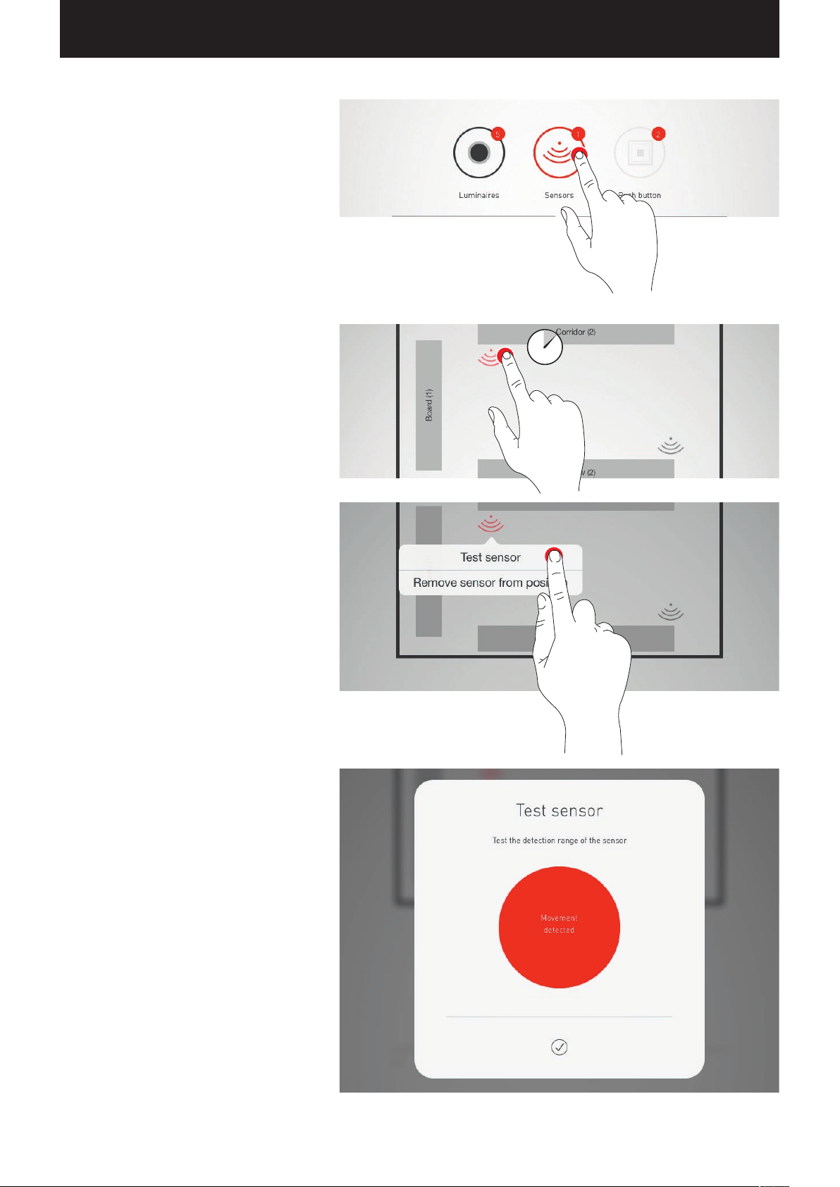
Assigning sensors
The assignment is performed analogously to the
luminaire assignment. In this, the control lamp of
the sensors serves for identification.
Testing the sensor
Subsequent to a long tap on a positioned sensor,
different functions can be called up.
The function “Testing the sensor” shows detected
movements. This way, the function of the sensor
and its detection range can be tested.
If a Dual HF sensor is utilised, the detection range
can, furthermore, be adjusted here.
Page 43
“LIVELINK INSTALL” APP / ROOM ADMINISTRATION / ROOM SETUP: ASSIGNMENT Page 43 / 77
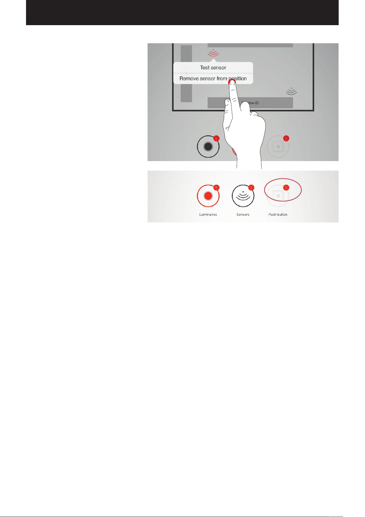
Remove sensor from position
With this function, a sensor can be removed from
the position. It is then available again in the bottom
area of the screen for a renewed assignment.
Push-buttons
The push-buttons are set up only in the next
steps. Shown are both the connected push-button
couplers as well as the push-button on the control
device.
Page 44
“LIVELINK INSTALL” APP / ROOM ADMINISTRATION / ROOM SETUP: ASSIGNING PUSH-BUTTONS Page 44 / 77
1.
ROOM SETUP: ASSIGNING PUSH-
Assigning push-buttons
BUTTONS
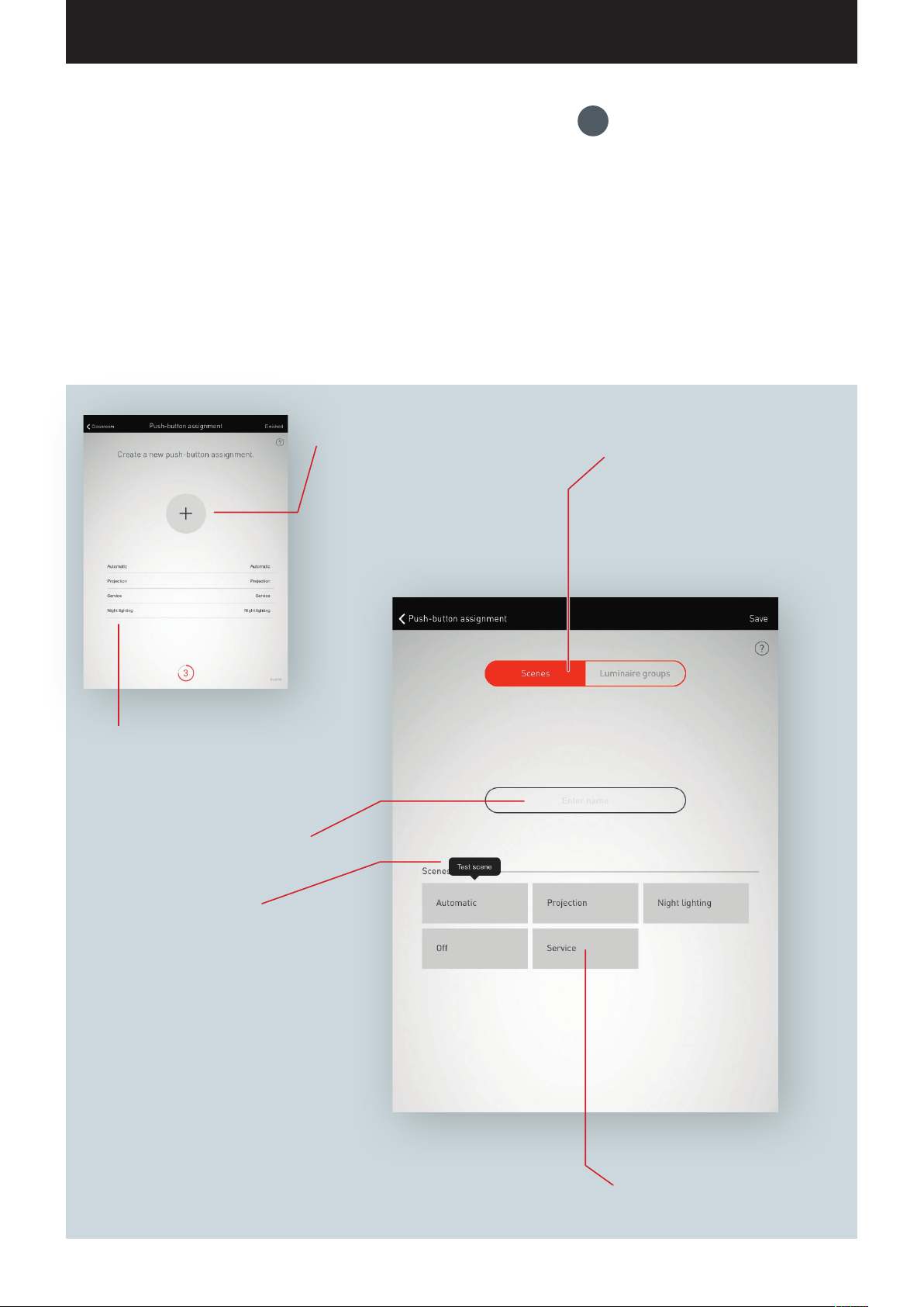
In this view, the push-buttons are connected to a light scene or a luminaire group
If a light scene is assigned to a push-button, this light scene is activated later upon
pushing the button.
If a luminaire is assigned to a push-button, the respective luminaire groups is
dimmed or switched later upon pushing the button (touch/dim function).
Only one single light scene can be assigned to a push-button. But not all pushbuttons and light scenes need to be linked.
New push-button assignments can be
created by tapping the plus symbol.
Choice between scenes and luminaire
groups.
A push-button either activates a light scene
or switches a luminaire group on or off,
respectively.
Listing all push-button assignments
set up.
Labelling the push-button assignment.
Testing the scene
Subsequent to a long tap on a scene, it
can be activated for a test.
Selecting the light scene or luminaire
group, respectively.
Page 45
“LIVELINK INSTALL” APP / ROOM ADMINISTRATION / ROOM SETUP: ASSIGNING PUSH-BUTTONS Page 45 / 77
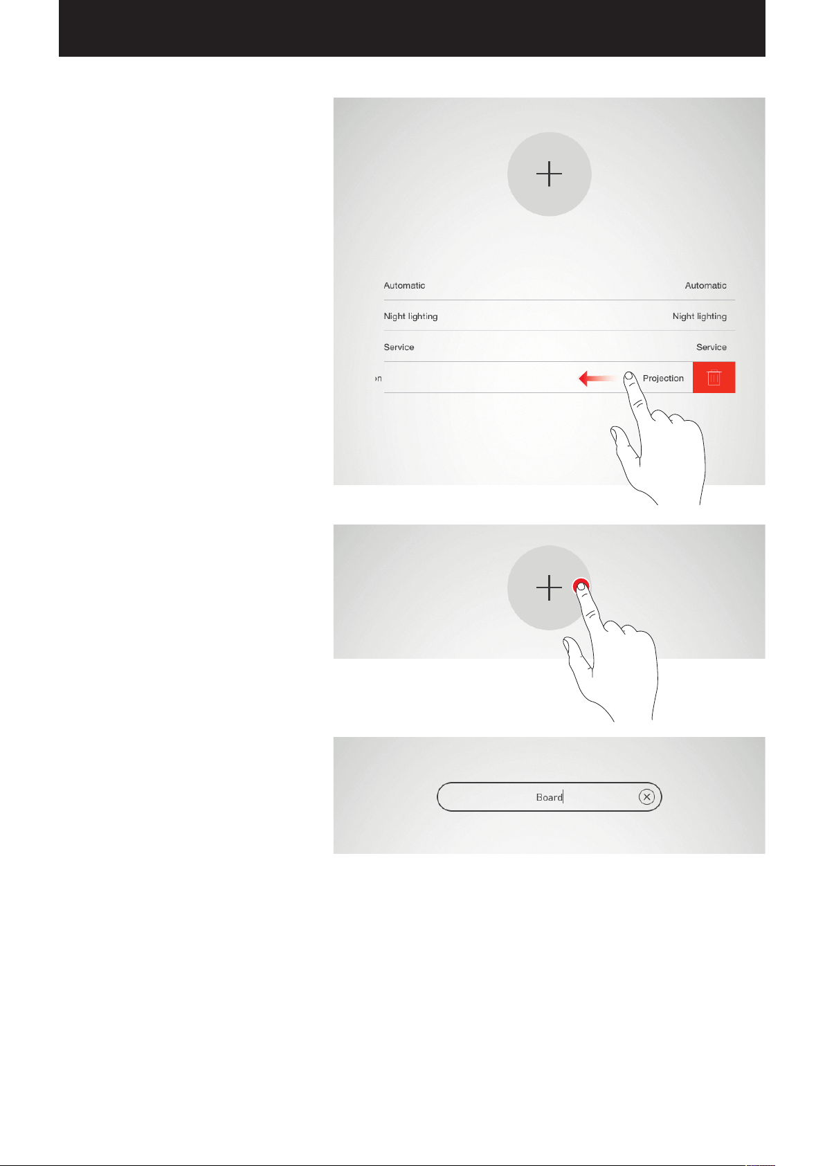
Listing all push-button assignments
In this view, all existing push-button assignments
are listed. By swiping to the side, the assignment
can be deleted.
Creating a new push-button assignment
A tap on the plus symbol starts the setup of a new
push-button assignment.
In the next view, the name for the assignment is
being assigned.
Page 46
“LIVELINK INSTALL” APP / ROOM ADMINISTRATION / ROOM SETUP: ASSIGNING PUSH-BUTTONS Page 46 / 77
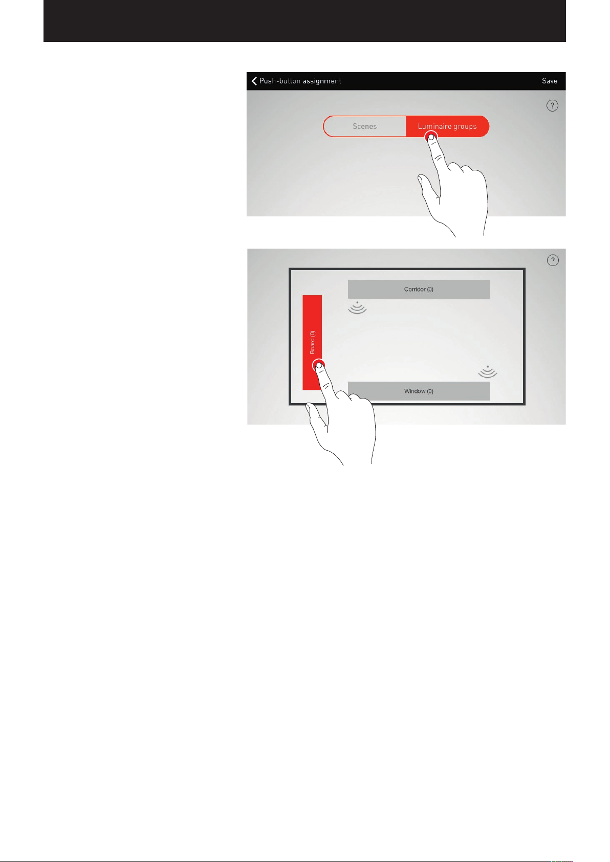
Selecting scenes / luminaire groups
Initially, it is selected whether the push-button is
intended to call up a light scene or to switch and
dim a luminaire group.
Depending on the selection all light scenes or all
luminaire groups are listed then, respectively.
Page 47
“LIVELINK INSTALL” APP / ROOM ADMINISTRATION / ROOM SETUP: ASSIGNING PUSH-BUTTONS Page 47 / 77
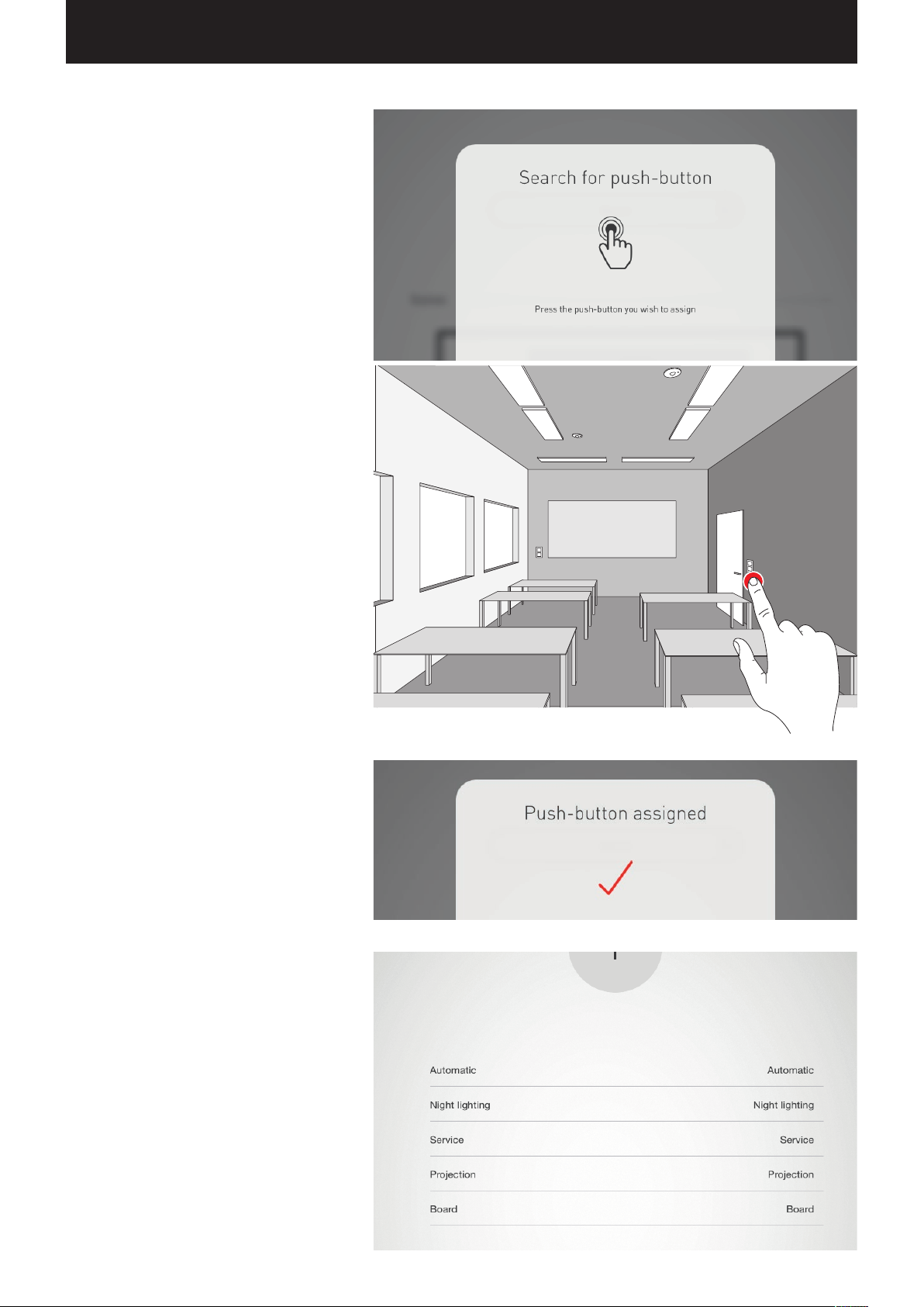
Assigning push-buttons
After the scene or luminaire group has been stored,
a window signals that LiveLink is now waiting for
the assignment of the push-button.
Now, the respective push-button must be pushed
and held (for up to 5 seconds) until the assignment
is confirmed in the window.
Additional push-button assignments and overwriting of assignments
The push-button assignment is concluded and is
listed in the list.
Now, additional push-button assignments can be
added. But not all push-buttons and light scenes
need to be linked.
If a selected push-button has already been assigned,
a note is being displayed. At this point, there is the
option to overwrite the existing assignment of this
push-button.
Page 48
“LIVELINK INSTALL” APP / ROOM ADMINISTRATION / CONCLUDING THE ROOM SETUP Page 48 / 77
1.
CONCLUDING THE ROOM SETUP
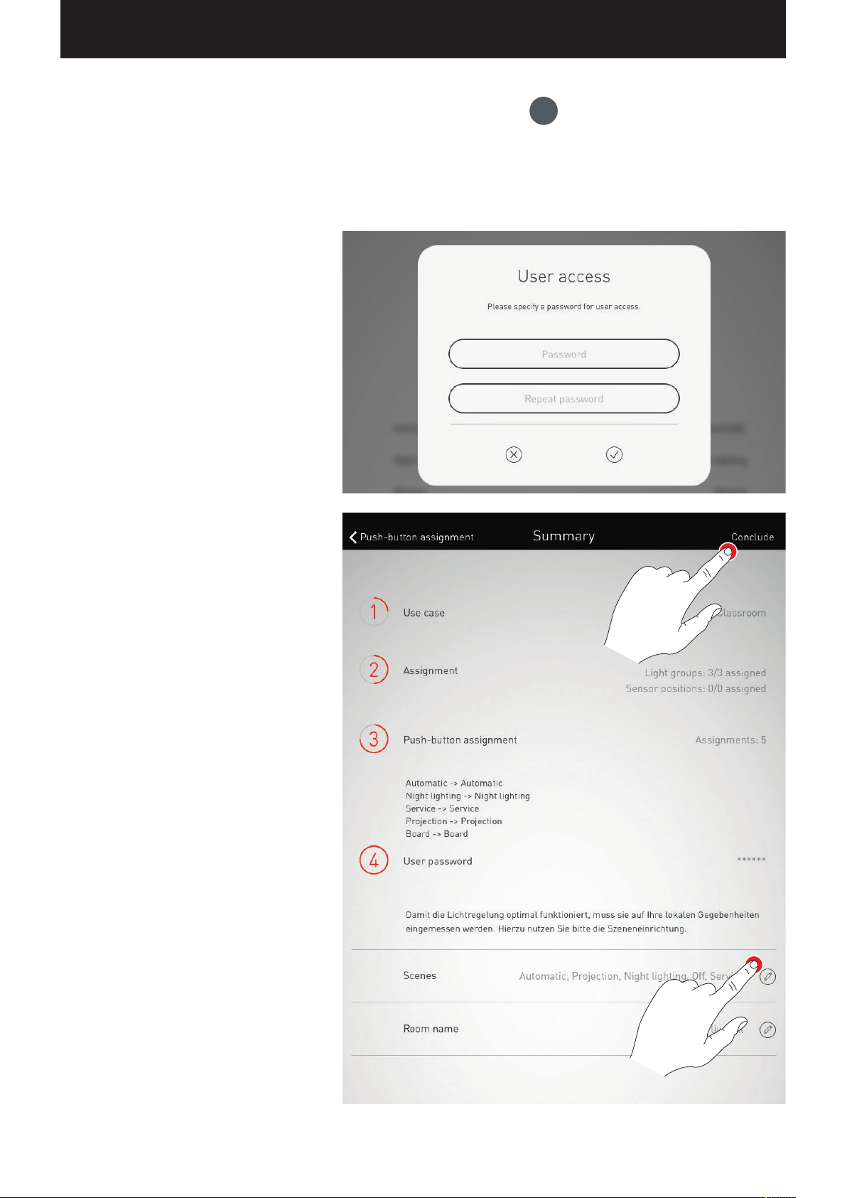
Upon conclusion, a user password is specified, and after a summary has been
checked, the room setup is concluded.
Specify user password
Subsequent to the completion of the push-button
assignment, a password for user access is specified.
The password serves for light control by the end
user via the “LiveLink Control” app.
Caution: Memorise the password!
Specify user password
Check the summary and apply optional settings
In this view, the room setup can be checked based
on a summary.
If changes are necessary, it is possible to jump back to
the preceding steps via the navigation in the title bar.
If now changes are necessary, the room setup is
concluded.
Applying option settings
The optional settings steps “Setting up scenes” and
“Rename room” can be carried out at this point.
These steps are described in the following chapters.
Page 49
“LIVELINK INSTALL” APP / ROOM ADMINISTRATION / ROOM SETUP: OPTION “RENAME ROOM” Page 49 / 77
ROOM SETUP: OPTION
“RENAME ROOM”
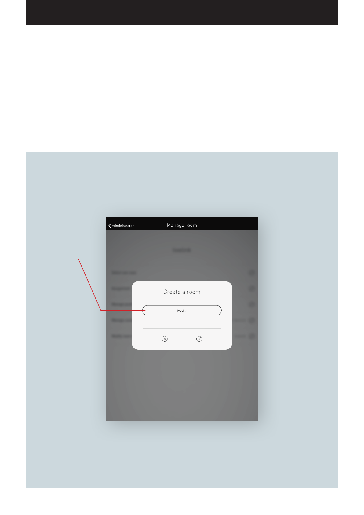
In this view, the room designation can be changed.
new name that is adopted as WLAN designation and as room designation for utilisation in the apps.
Room name
After tapping this box, the
keyboard is displayed to enter
a new room name.
The room receives a
Page 50
“LIVELINK INSTALL” APP / ROOM ADMINISTRATION / ROOM SETUP: OPTION “RENAME ROOM” Page 50 / 77
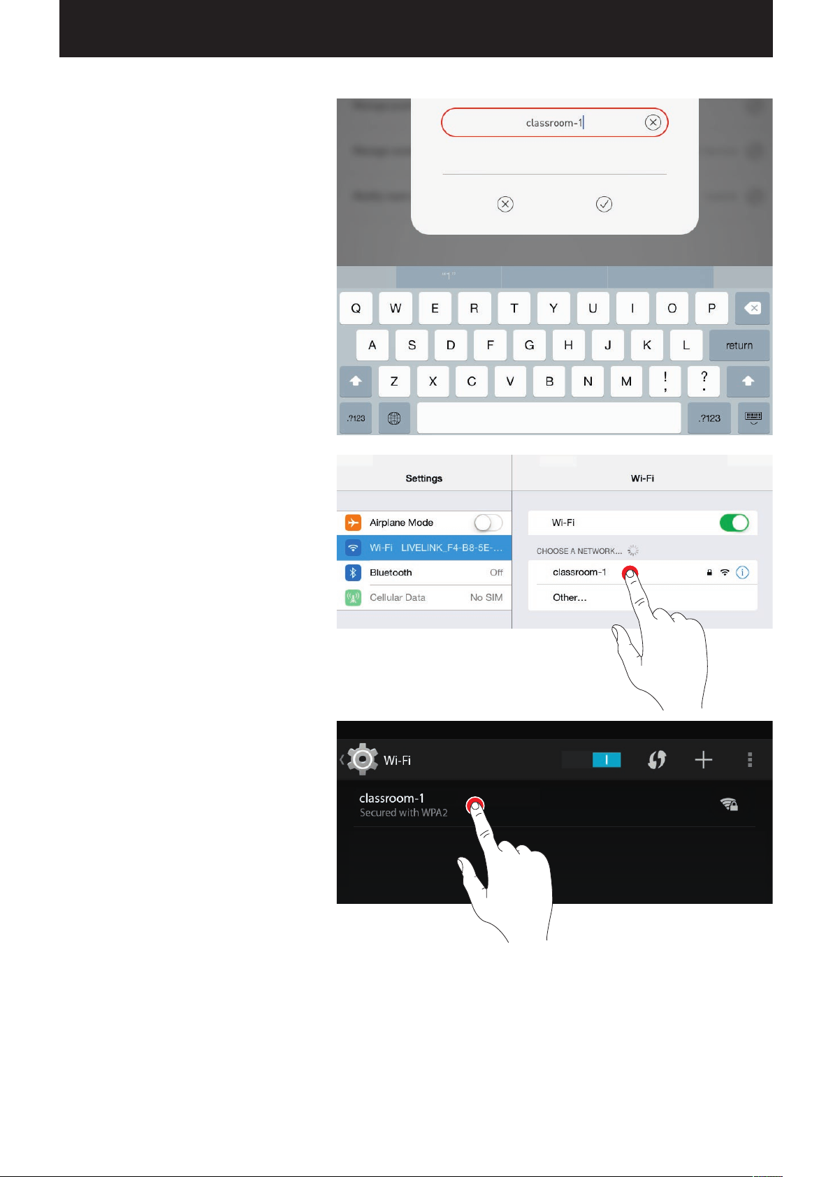
Change room name
After tapping “Change room name”, a new room
name can be entered.
Reconnecting the WLAN
By renaming the room name, the WLAN also adopts
this room name automatically. Therefore, the WLAN
connection must be re-established.
Page 51
“LIVELINK INSTALL” APP / ROOM ADMINISTRATION / ROOM SETUP: OPTION “ADMINISTRATE SCENES” Page 51 / 77
ROOM SETUP:
OPTION “ADMINISTRATE SCENES”
In this view, light scenes are administrated and set up.
Typical scenes are included in the Use Case delivery. Additional scenes can
be created completely from scratch or duplicated from existing scenes. Of
course, all configuration options are available in either case.
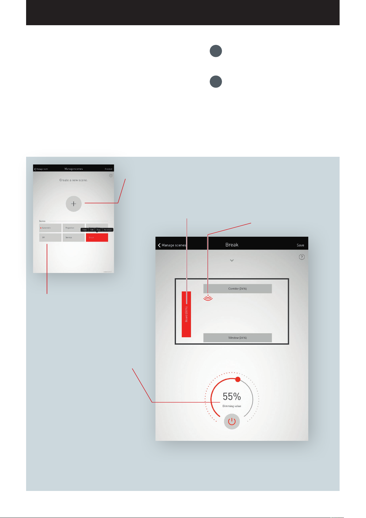
A light scene consists of dimming settings of the individual luminaire groups
as well as sensor options. Depending on the equipment, the sensors can be
utilised for presence detection and/or constant light control. Different sensor
settings are available for both modes of operation.
New scenes can be created and configured
by tapping the plus symbol.
The dimming value of the individual
groups is specified in percent.
A group is activated by tapping it and
the value can be configured.
1.
Creating the illumination
settings of a scene
2.
Setting the sensor system
of a scene
Provides access to the
sensor options.
Selecting predefined scenes. Prede-
fined scenes contain typical settings
for light situations. The default scene is
marked with this dot, for the behaviour
e.g. upon switching mains power on.
Control wheel for the setting of
the dimming values of the luminaire groups or of the control
parameters of the sensors.
Page 52
“LIVELINK INSTALL” APP / ROOM ADMINISTRATION / ROOM SETUP: OPTION “ADMINISTRATE SCENES” Page 52 / 77
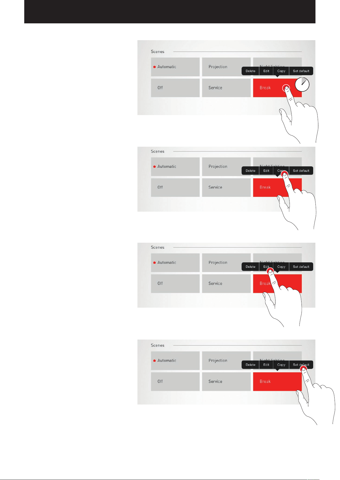
Listing all scenes
In this view, all existing scenes are listed. With a
long tap on a scene, a context menu is opened.
Here, the scene can be deleted, edited, copied, or
specified as the default scene.
Copy scene
With a tap on “Copy”, this scene is copied with all
settings. In the next step, a new name is assigned.
The subsequent steps guide through the setup of
the scene; they are identical to the setup of new
scenes which are described on the following pages.
Edit scene
Tapping on “Edit” starts the editing of the scene. The
subsequent steps are identical to the new setup of
scenes which are described on the following pages.
Set default scene
The default scene is activated automatically every
time the system is switched on.
By tapping “Set default”, this scene is specified as
the default. A dot in front of the scene designation
identifies this characteristic.
Page 53
“LIVELINK INSTALL” APP / ROOM ADMINISTRATION / ROOM SETUP: OPTION “ADMINISTRATE SCENES” Page 53 / 77
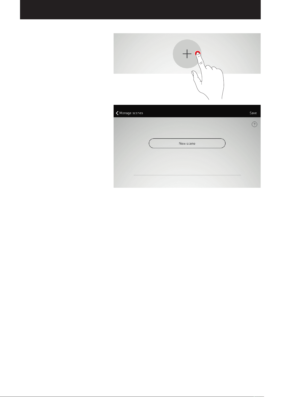
Creating a new scene
A tap on the plus symbol starts the setup of a new
scene.
On the next screen, the name is assigned.
Page 54
“LIVELINK INSTALL” APP / ROOM ADMINISTRATION / ROOM SETUP: OPTION “SETTING UP SCENES” Page 54 / 77
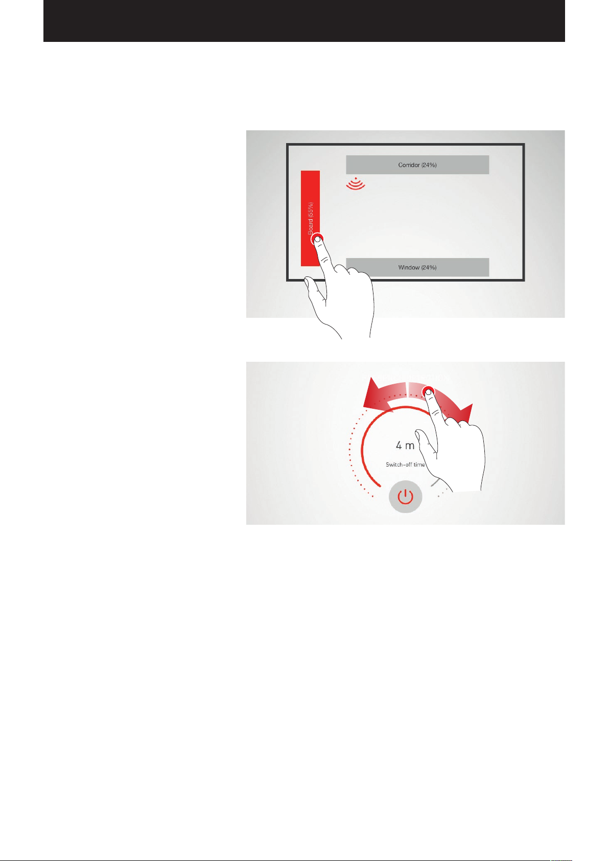
ROOM SETUP: OPTION “SETTING UP SCENES”
In this view, dimming values as well as sensor options can be adjusted now.
Selecting luminaire groups
A luminaire group is activated by tapping on it; an
active luminaire group is shown in red.
Multiple luminaire groups can be activated one after
another in order to configure them at the same time.
Specifying the dimming value
The activated luminaire groups can be dimmed to
the desired level with the control wheel.
Page 55
“LIVELINK INSTALL” APP / ROOM ADMINISTRATION / ROOM SETUP: OPTION “SETTING UP SCENES” Page 55 / 77
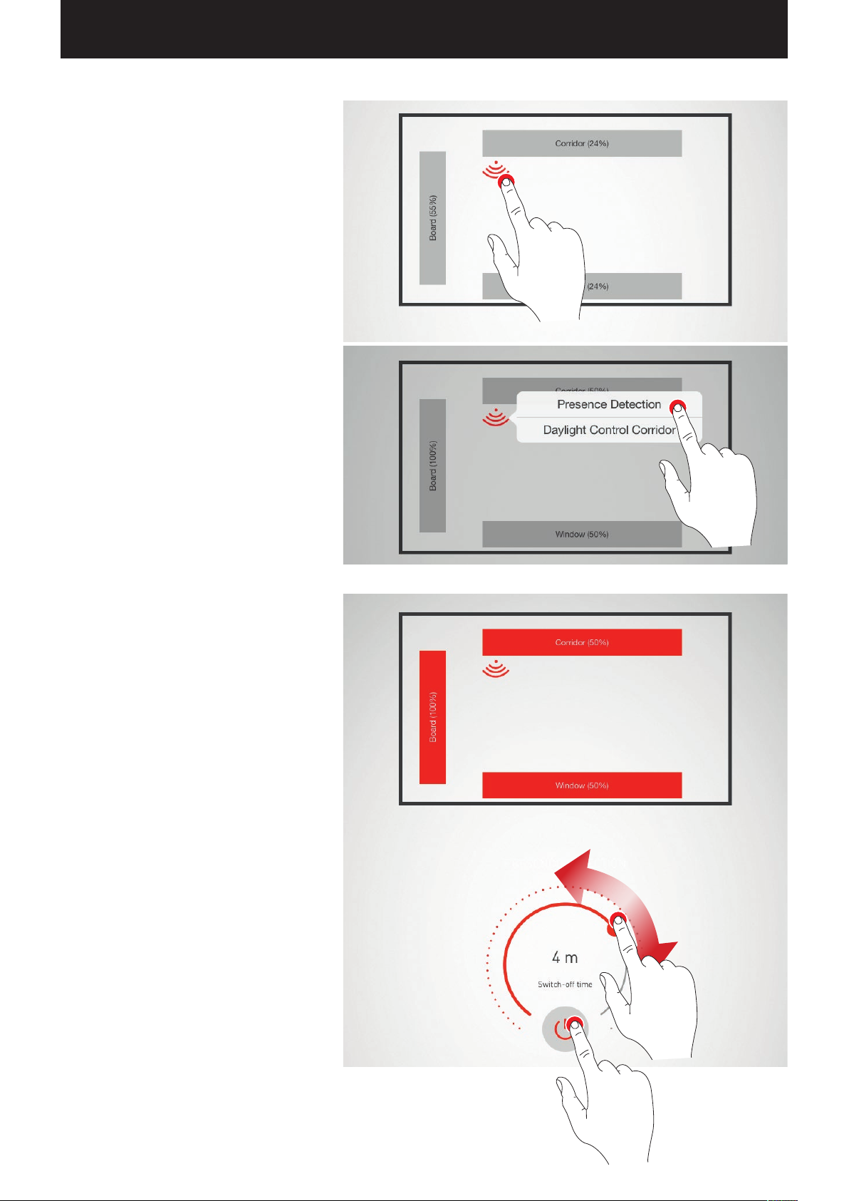
Configuring a sensor
By tapping a sensor, the sensor functions are offered.
Depending on the sensor utilised, a presence
detection and/or a constant light control can be
configured.
Subsequent to the selection of a function, the luminaire
groups linked with this function are provided with
a red background. The assignment of the sensor
controls to the luminaire groups takes place in the
luminaire assignment (see chapter “Room setup:
Assignment”).
Setting up the presence detection
Tapping on the sensor symbol (at the control wheel)
activates and/or deactivates the sensor.
The switch-off delay is set with the control wheel.
Page 56
“LIVELINK INSTALL” APP / ROOM ADMINISTRATION / ROOM SETUP: OPTION “SETTING UP SCENES” Page 56 / 77
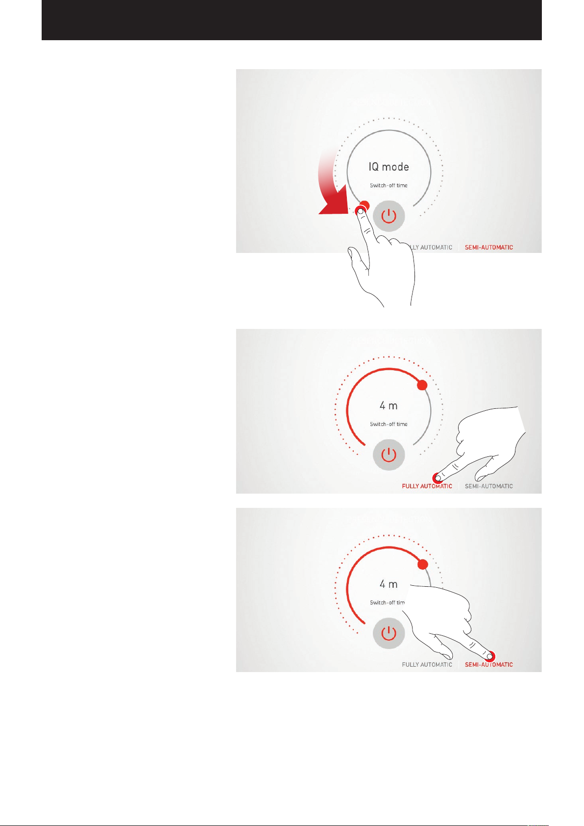
Presence detection: IQ mode
If the switch-off delay is set to “0” with the control
wheel, the IQ mode is activated.
The IQ mode analyses the utilisation of the room
based on the detected movements.
In IQ mode, the delay period is between 5 and 20
minutes long.
If a lot of movements are registered, the delay period
doubles, if hardly any movements are registered,
the delay period is cut in half.
In case of constant utilisation of the room, this does,
for example, result in the illumination not being
shut off directly when somebody leaves the room
or if somebody is not moving for a while. But if the
room is used only sporadically, the delay period is
automatically reduced to 5 minutes.
Presence detection: Fully automatic
The illumination is switched on and off automatically,
depending on brightness and presence detection.
Presence detection: Semi-automatic
The illumination is only switched off automatically
in this case. The switching on is performed manually.
Page 57
“LIVELINK INSTALL” APP / ROOM ADMINISTRATION / ROOM SETUP: OPTION “SETTING UP SCENES” Page 57 / 77
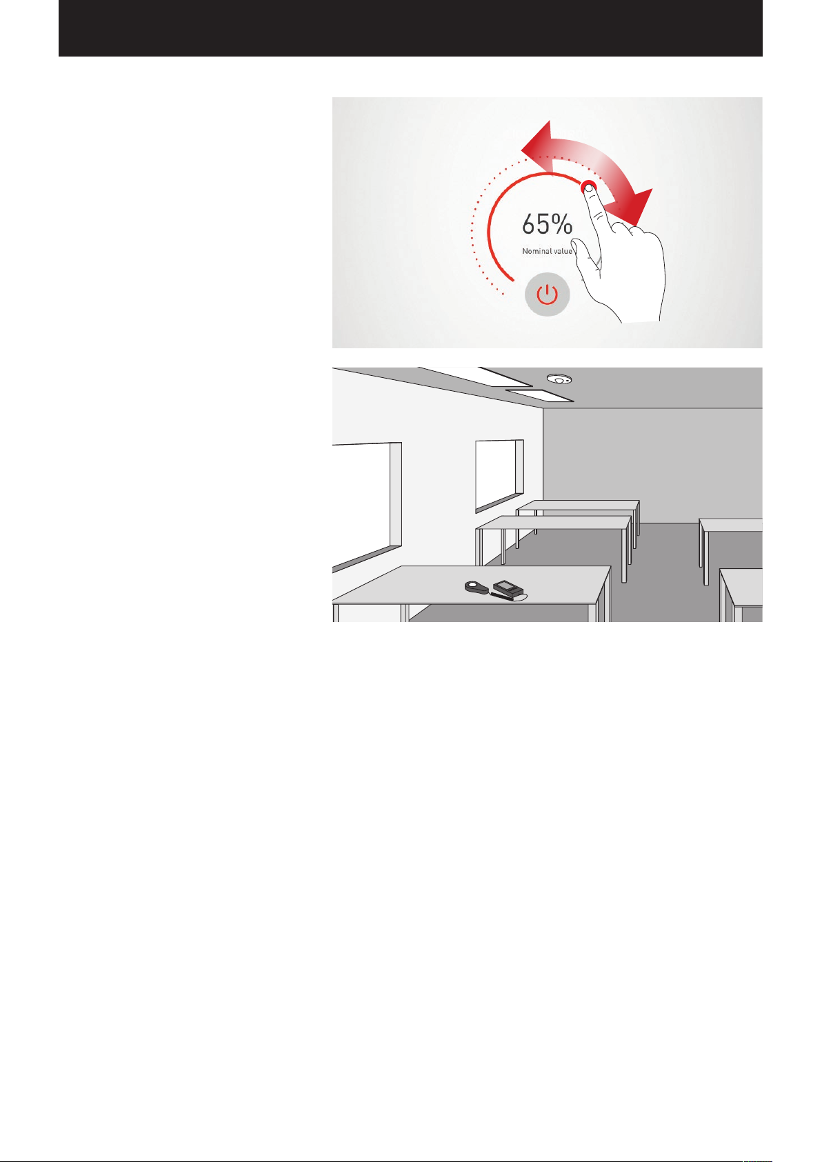
Setting up constant light control
In case of constant light control, the sensor is
continuously measuring the brightness in the room.
The automatic control adjusted the brightness of the
illumination in order to compensate for the changes
of the exterior light. This way, it ensures a constant
brightness at the highest efficiency.
Subsequent to selecting constant light control, the
desired brightness of the room is set via the control
wheel and stored as reference value.
Constant light control: In the calibration of the
light control, the following notes must be taken
into consideration:
• The calibration of the illuminance should be per-
formed with as little daylight as possible.
• Sources of interference and the casting of shad-
ows on the area to be calibrated must be avoided.
(See chapter “Sensor placement”)
Page 58
“LIVELINK INSTALL” APP / ROOM ADMINISTRATION / ROOM SETUP: OPTION “SETTING UP SCENES” Page 58 / 77
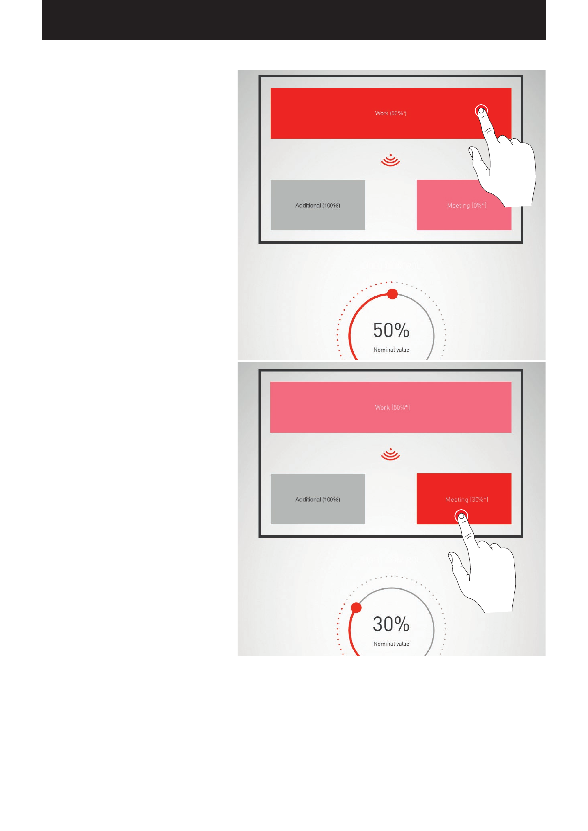
Constant light control: Setting the offset
For a uniform and efficient illumination, it may be
sensible to undertake a separate control of luminaires
that are close to the window and that are far from
the window.
If only one sensor is available, an offset setting may
be applied:
Once the constant light control has been activated,
the luminaires that are linked to this function are
marked in colour. By tapping the luminaire groups,
these can be activated and/or deactivated and as
such different target values can be set.
Caution: The target values are set for the condition
maximum incident daylight. If daylight is available
during the setup, the target values can be adjusted
optimally while observing the light distribution. If
no daylight is available, the target values must be
estimated.
Caution: For separate control of luminaires close
to the window and luminaires far from the window,
an individualised control with multiple sensors that
adjust the different luminaire groups separately is
better suited.
of
Page 59
“LIVELINK INSTALL” APP / ROOM ADMINISTRATION / ROOM ADMINISTRATION Page 59 / 77
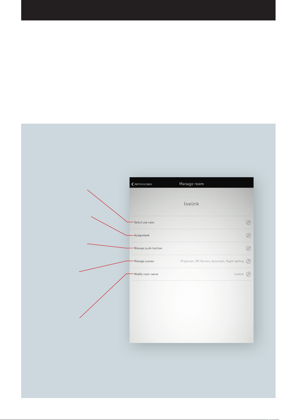
ROOM ADMINISTRATION
In the room administration, all items of the room setup can be called up and
changed after the fact. The operation of this menu is identical to the initial setup
and will not be explained further here.
Select Use Case
Selecting a matching Use Case
Assignment
Assignment of luminaires and
sensors
Administrate push-buttons
Assignment of push-buttons
to luminaire groups and/or
light scenes.
Administrate scenes
Administration of light scenes
existing from the Use Case as
well as setup of individualised
light scenes.
Renaming a room
Changing the designation of
the room. The WLAN name is
adapted to the changed room
designation.
Page 60
“LIVELINK INSTALL” APP / ROOM ADMINISTRATION / SETTINGS Page 60 / 77
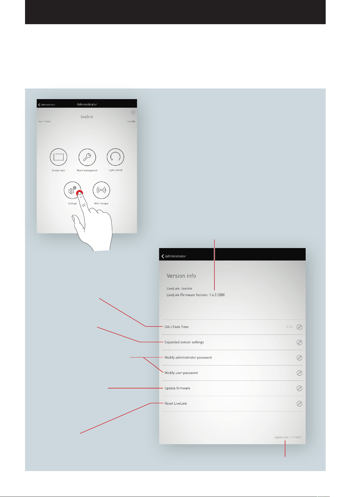
SETTINGS
The “Settings” view in the administrator menu displays important
system information and covers the basic settings of the LiveLink
control device.
DALI fade time
Setting of the transition time between the dimming levels.
Expanded sensor settings
Change password
of administrator account and user account
Update firmware
Updating the operating software
of the LiveLink control device.
Information of the control device
Room designation and firmware version
Reset LiveLink
to delivery condition
Version info of the app
Page 61
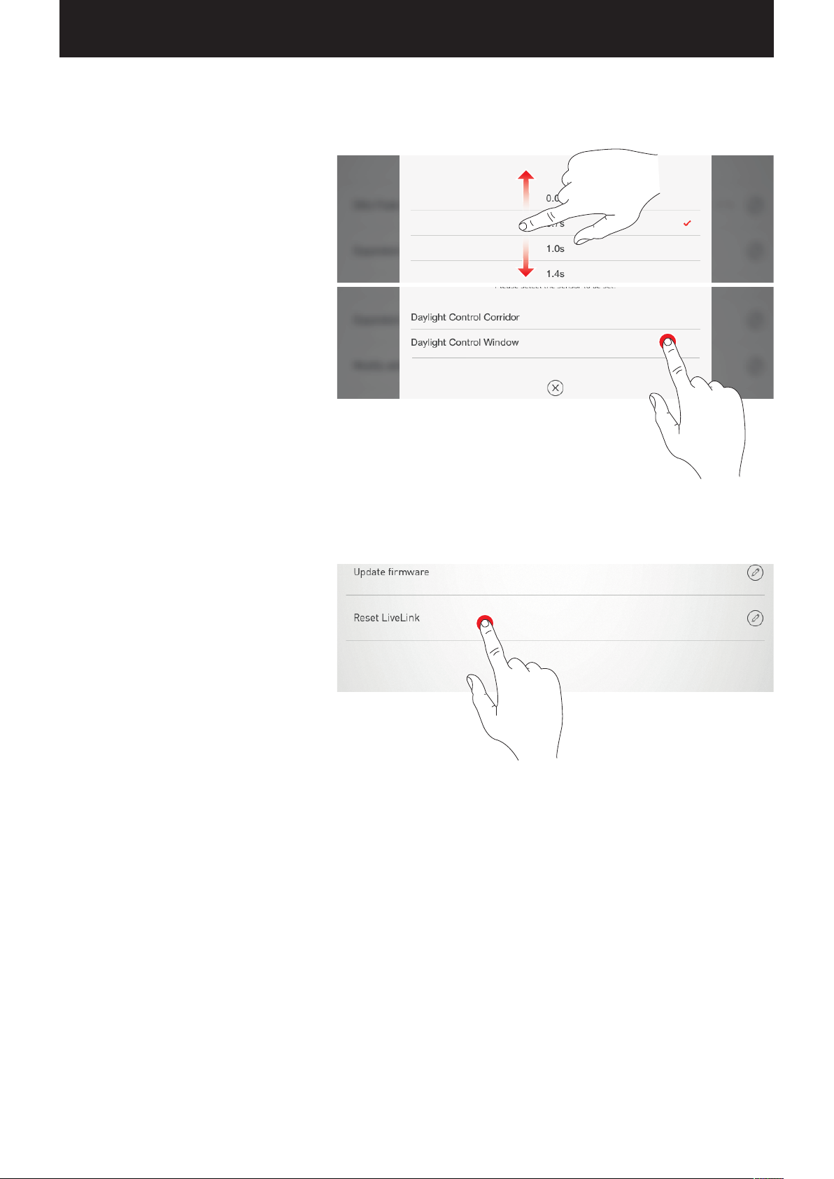
“LIVELINK INSTALL” APP / ROOM ADMINISTRATION / SETTINGS: DALI FADE TIME Page 61 / 77
SETTINGS: DALI FADE TIME
The DALI fade time controls the transition time
between the dimming levels. In case of a setting of
“0 s”, the brightness is changed without dimming
function. The longer the transition time, the softer
the dimming process appears to be.
To change the DALI fade time, the desired time is
selected by swiping vertically and subsequently
stored by tapping on “Accept DALI fade time”.
SETTINGS: RESET LIVELINK AND HARDWARE RESET
After tapping “Reset LiveLink” and subsequent
confirmation, the LiveLink control device is reset to
delivery condition.
Caution: All settings will be deleted!
For a hardware reset, the DALI connections are
short-circuited (connecting both DALI lines) and at
the same time the internal push-button on the control
device is held down for 20 seconds. For this, a
push-button should be connected to the designated
interfaced (S) of the LiveLink system.
Page 62
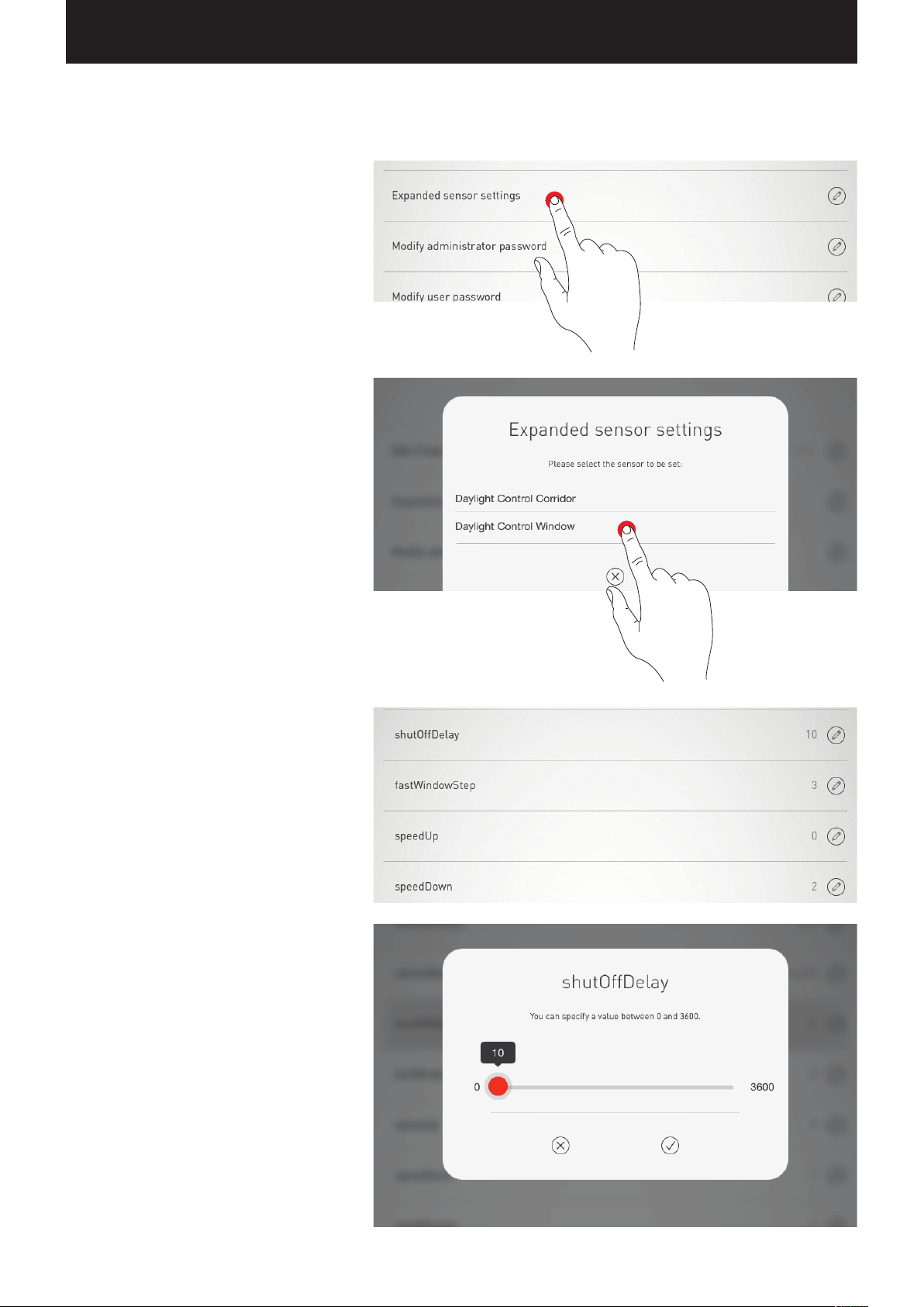
“LIVELINK INSTALL” APP / ROOM ADMINISTRATION / SETTINGS: ADVANCED SENSOR SETTINGS Page 62 / 77
SETTINGS: ADVANCED SENSOR SETTINGS
Tapping on “Advanced sensor settings” provides
access to detailed settings of the sensors.
The functions that can be adjusted are dependent of
the sensor used. Typical default values are already
pre-set; in most cases, these do not need to be
adjusted.
All sensors are listed.
Here, the desired sensor can be selected.
In this view, the settings options for the sensor are
listed.
Subsequent to tapping on a sensor function, the
value can be changed and stored.
The different sensor functions are described in the
table below.
Page 63

“LIVELINK INSTALL” APP / ROOM ADMINISTRATION / SETTINGS: ADVANCED SENSOR SETTINGS Page 63 / 77
Parameter
SwitchMode SwitchBoth Fully automatic operation
shutOffDelay 5 minutes 0-60 minutes Shut-off delay in minutes
switchOffTimeOut
Presence detection
TurnOnValue 100 % is set in the Use Case Is part of the control. If the control is switched on again via a
SwitchMode SwitchBoth SwitchBoth
ShutOFFDelay 300 0-3600 seconds Shut-off delay at the control after exceeding the turn-off
TurnOffThreshold 25 % 0-100 %
NominalValue 500 lx 0-1024 lx Target value to which the system adjusts
Dogleg 235 0-254 Breakpoint at which the set offset is regulated to 0
Constant light control
SlowWindow 5 0-20
SlowWindowStep 1 0-20 Step width around the nominal value
FastWindow 10 0-40 Other ranges in which control is exercised at reduced speed
FastWindowStep 3 0-20 Step width in other ranges
SpeedDown 2 0-20 Speed of adjusting down
SpeedUp 0 0-20 Speed of adjusting up
Default
setting
0-3600
seconds
Variables Explanation
Fully/semi-automatic operation
Semi-automatic operation
is set in the Use Case Inverse time of presence detection. Time that must pass with-
OnlySwitchON
OnlySwitchOFF
Fully automatic: Switching on and off automatically
Semi-automatic: Switching off automatically,
switching on manually via push-button
out movement after a manual intervention in order to return to
automatic operation.
presence sensor in “light mode”, this start value is used. In
case of a configuration that loads the default scene upon being
switched on, this value is pointless and is not being utilised
Switching behaviour in case of sufficient daylight
SwitchBoth: Switching on and off automatically in case
of a sufficient share of daylight
OnlySwitchOn: No daylight-depending switching off,
the illumination remains at
a minimum level
OnlySwitchOFF: Automatic daylight-dependent switching
off, but not switching back on upon dropping below the target value
threshold
Turn-off threshold, at which the system turns the illumination off
(measured at the sensor)
Range around the nominal value in which no control is exercised
Page 64
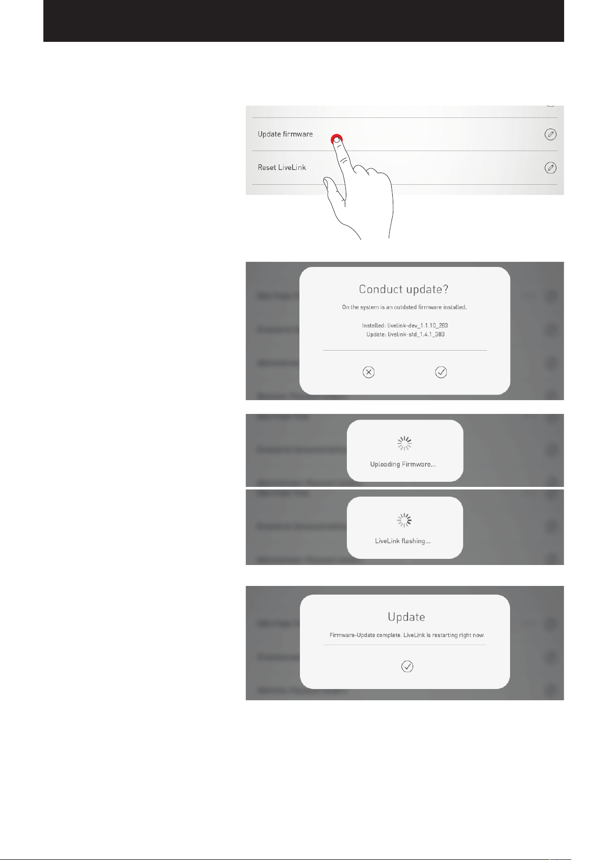
“LIVELINK INSTALL” APP / ROOM ADMINISTRATION / SETTINGS: UPDATE FIRMWARE Page 64 / 77
SETTINGS: UPDATE FIRMWARE
Tapping on “Update firmware” starts the update
process of the operating software of the LiveLink
control device.
The most current firmware is transferred from the
app to the control device via WLAN and installed on
it. For this, no Internet connection is necessary.
Caution: The firmware is stored in the “LiveLink
Install” app. To ensure that the most current firmware is being utilised, the app should be updated
in advance. (Typical update process via the Apple
App Store on iOS devices or the Google Play Store
on Android devices; Internet connection required)
A window shows which version is currently installed
and to which version an update can be performed.
Upon confirmation, the firmware is uploaded to
and subsequently installed on the control device
(”LiveLink flashing”).
A window indicates the completion of the update.
The system restarts. The app then displays the
room selection view again
Page 65
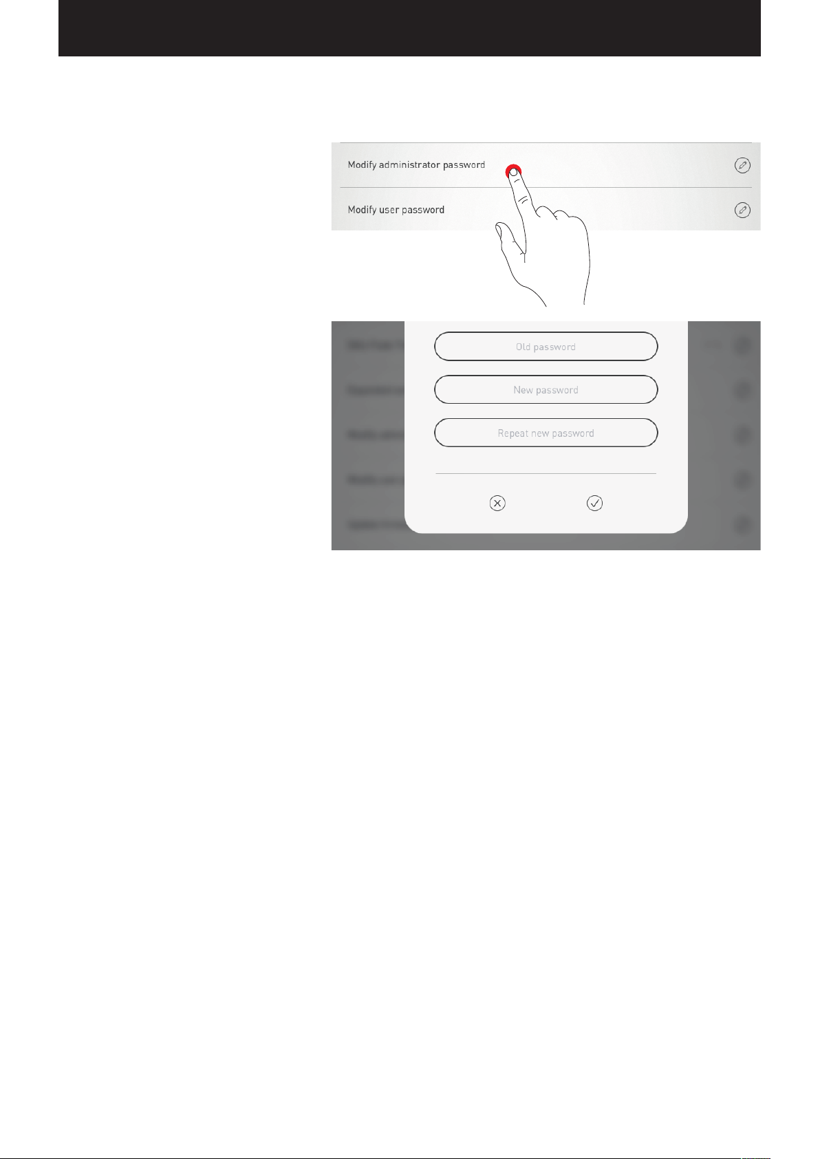
“LIVELINK INSTALL” APP / ROOM ADMINISTRATION / SETTINGS: CHANGE PASSWORDS Page 65 / 77
SETTINGS: CHANGE PASSWORDS
The administrator password and the user password
can be changed at any time.
The respective function is called and the old password
must be entered first. The new password must be
entered twice.
Page 66
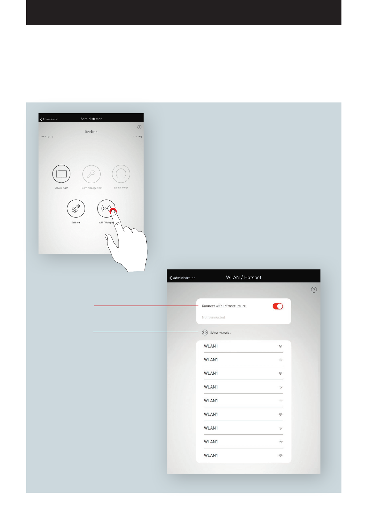
“LIVELINK INSTALL” APP / ROOM ADMINISTRATION / WLAN: CONNECT TO INFRASTRUCTURE Page 66 / 77
WLAN: CONNECT TO INFRASTRUCTURE
The LiveLink control device can be connected to an existing infrastructure WLAN. The LiveLink room then is available on the existing
network for configuration and operation.
Switching on/off
as well as setup of the connection
Change password
For an already existing connection
Page 67
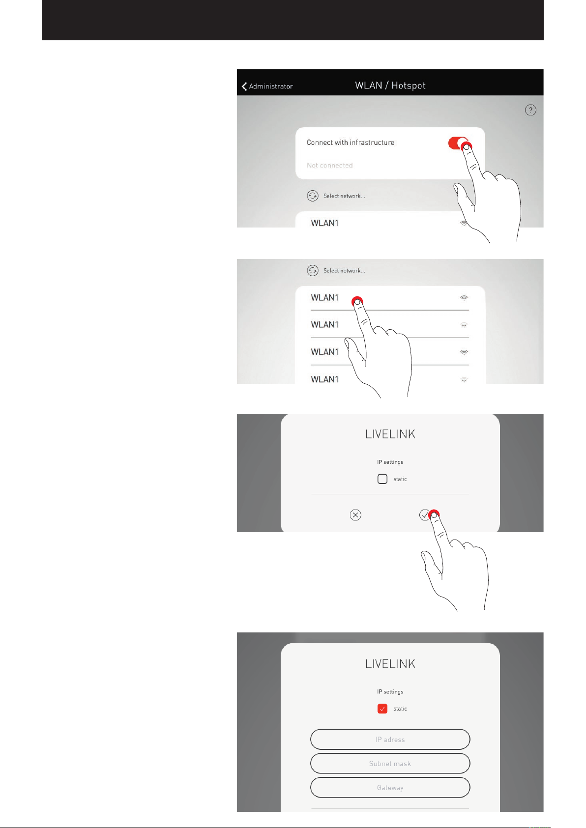
“LIVELINK INSTALL” APP / ROOM ADMINISTRATION / WLAN: CONNECT TO INFRASTRUCTURE Page 67 / 77
Switching on configuration of an infrastructure
Select network
All available WLANs are listed. The desired WLAN
is selected
IP setting: dynamic (DHCP)
If the LiveLink control device is to be assigned an IP
dynamically by the existing network (DHCHP), the
“static” filed remains deactivated.
IP setting: static
As an alternative, static IP settings can be applied.
Page 68
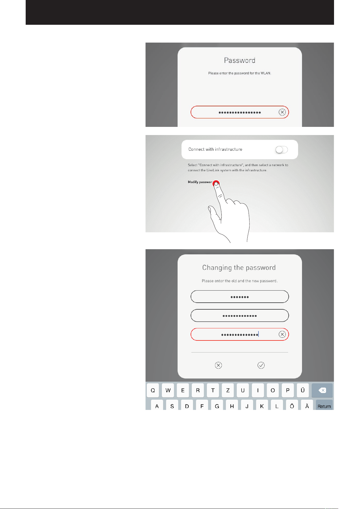
“LIVELINK INSTALL” APP / ROOM ADMINISTRATION / WLAN: CONNECT TO INFRASTRUCTURE Page 68 / 77
Enter WLAN password
Upon entering the password for the infrastructure
WLAN, the connection is established.
Change WLAN password
For an existing infrastructure connection, the WLAN
password can be changed.
Page 69
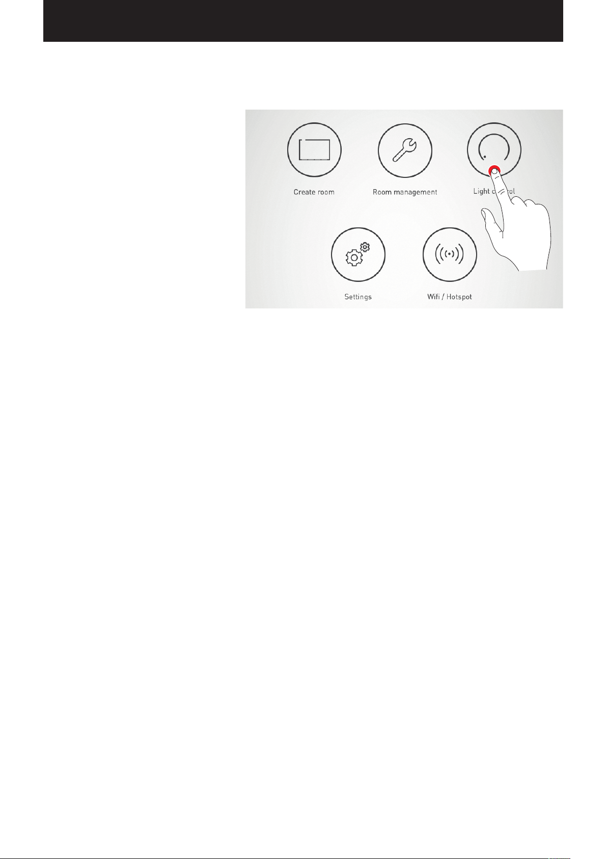
“LIVELINK INSTALL” APP / OPERATING THE LIGHT CONTROL Page 69 / 77
OPERATING THE LIGHT CONTROL
The light control of the already selected room can
be called up directly in the administration menu of
the “LiveLink Install” app. The operation is identical
to the functionality of the “LiveLink Control” app;
see corresponding chapter for the app.
Caution: The light control can be selected only if
the room was completely set up.
Page 70
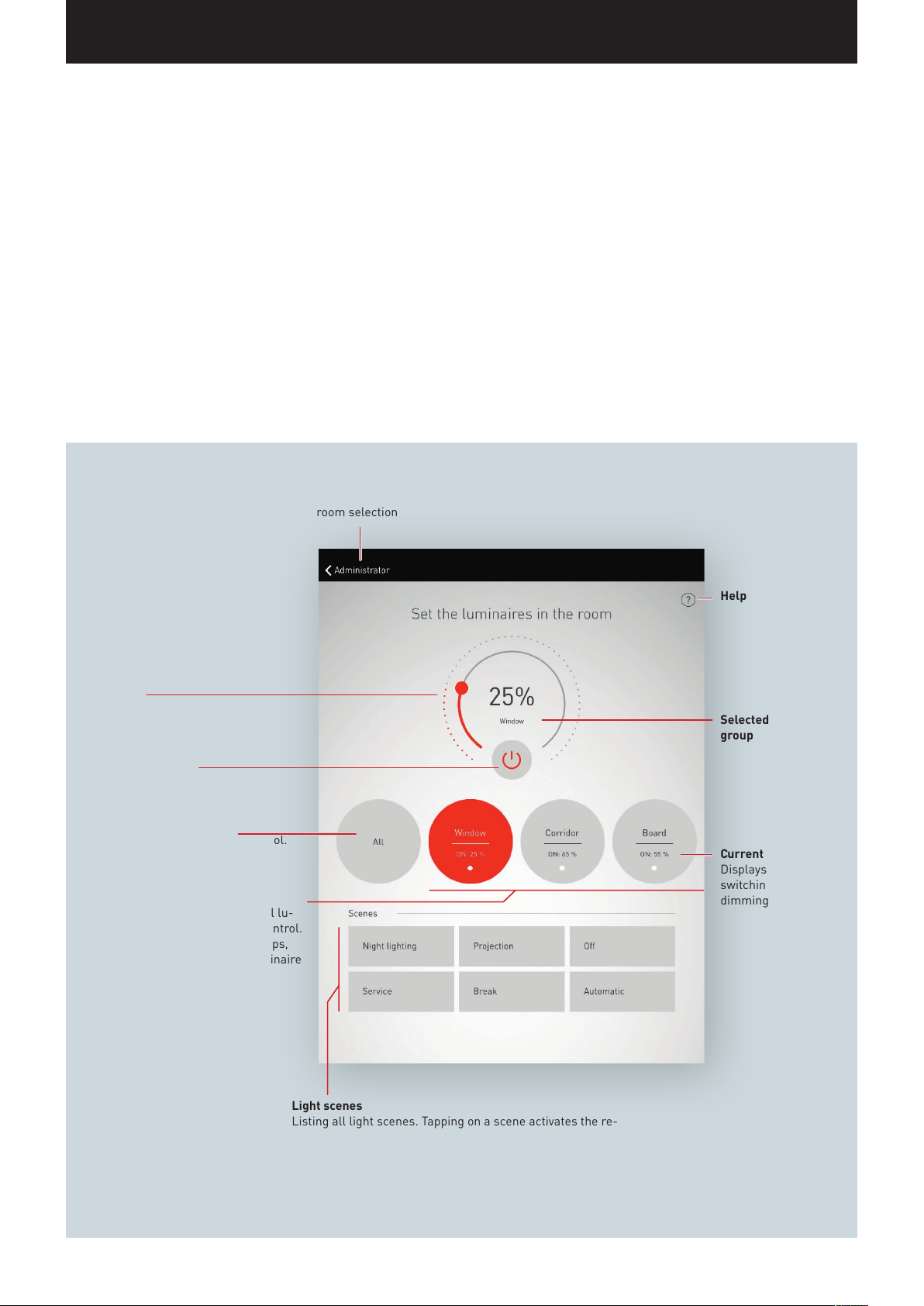
“LIVELINK CONTROL” APP / OVERVIEW Page 70 / 77
“LIVELINK CONTROL” APP
OVERVIEW
The completely set up system can be controlled via the LiveLink apps.
The user is able to dim, switch on and switch off individual luminaire
groups or the whole system. In addition, previously created scenes
can be selected.
The light control is operated via the “LiveLink Control” app, but can
also be carried out via the “LiveLink Install” app.
Dimming
of the selected luminaire group
Switching on/off
of the selected luminaire group
Select all luminaires
Selects all luminaires for light control.
Select individual luminaire groups
Allows for the selection of individual lu-
minaire groups for separate light control.
In case of numerous luminaire groups,
you can navigate to the desired luminaire
group by swiping.
Back to
room selection
Help
Selected luminaire
group
Current status
Displays the current
switching state and
dimming value.
Light scenes
Listing all light scenes. Tapping on a scene activates the re-
spective illumination setting.
In case of numerous scenes, you can navigate through the list
by swiping.
Page 71
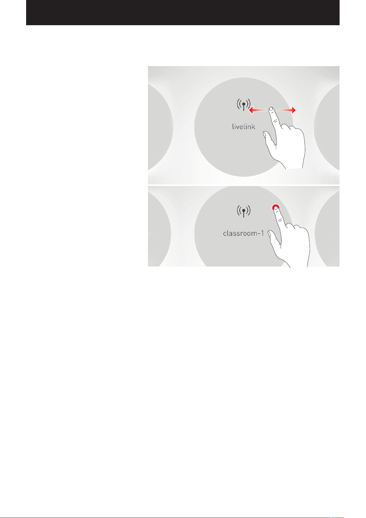
“LIVELINK CONTROL” APP / SELECT ROOM / WLAN: CONNECT TO INFRASTRUCTURE Page 71 / 77
SELECT ROOM
When the app is started, the “Select room” view is
already active. The app searches for LiveLink rooms
on the network.
The desired room can be located by swiping and can
subsequently be selected.
Caution: The tablet and/or smart phone must be
connected to the LiveLink control device via WLAN.
Either directly to the WLAN of the control device or to
an existing infrastructure WLAN (see chapter “WLAN”)
Page 72
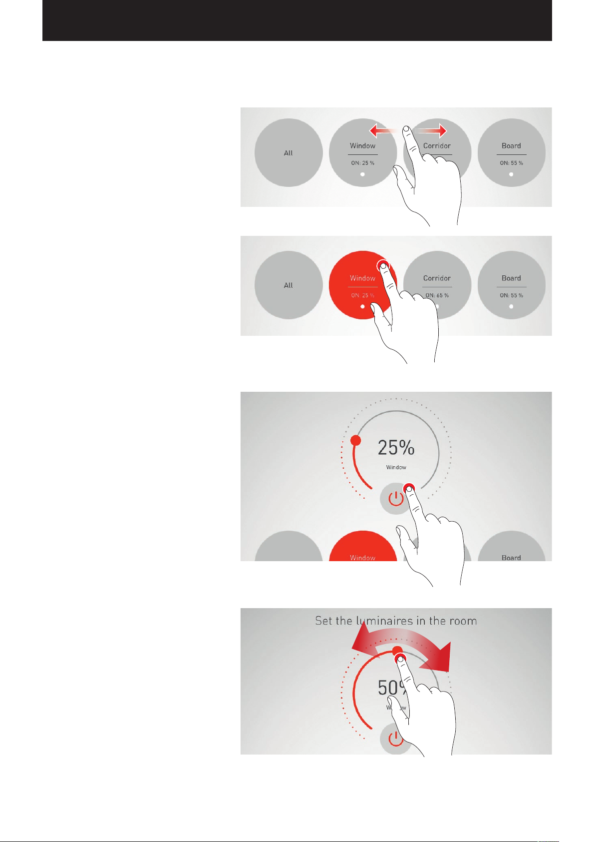
“LIVELINK CONTROL” APP / MANUAL SETTING OF THE ROOM ILLUMINATION Page 72 / 77
MANUAL SETTING OF THE ROOM ILLUMINATION
Select a luminaire group
First, a luminaire group is selected for which the
state of illumination is to be changed. In case of
numerous luminaire groups, you can navigate by
swiping.
For each luminaire group the current state and dimming level are displayed.
With the field “All”, all luminaire groups are selected.
Switching a luminaire group on/off
The currently selected luminaire group and the
dimming value are being displayed in the control
wheel.
By tapping the on/off button, the luminaire group is
switched on (red symbol) or switched off
(grey symbol).
Dimming a luminaire group
A dimming value for the active luminaire group is
specified via the control wheel.
Page 73
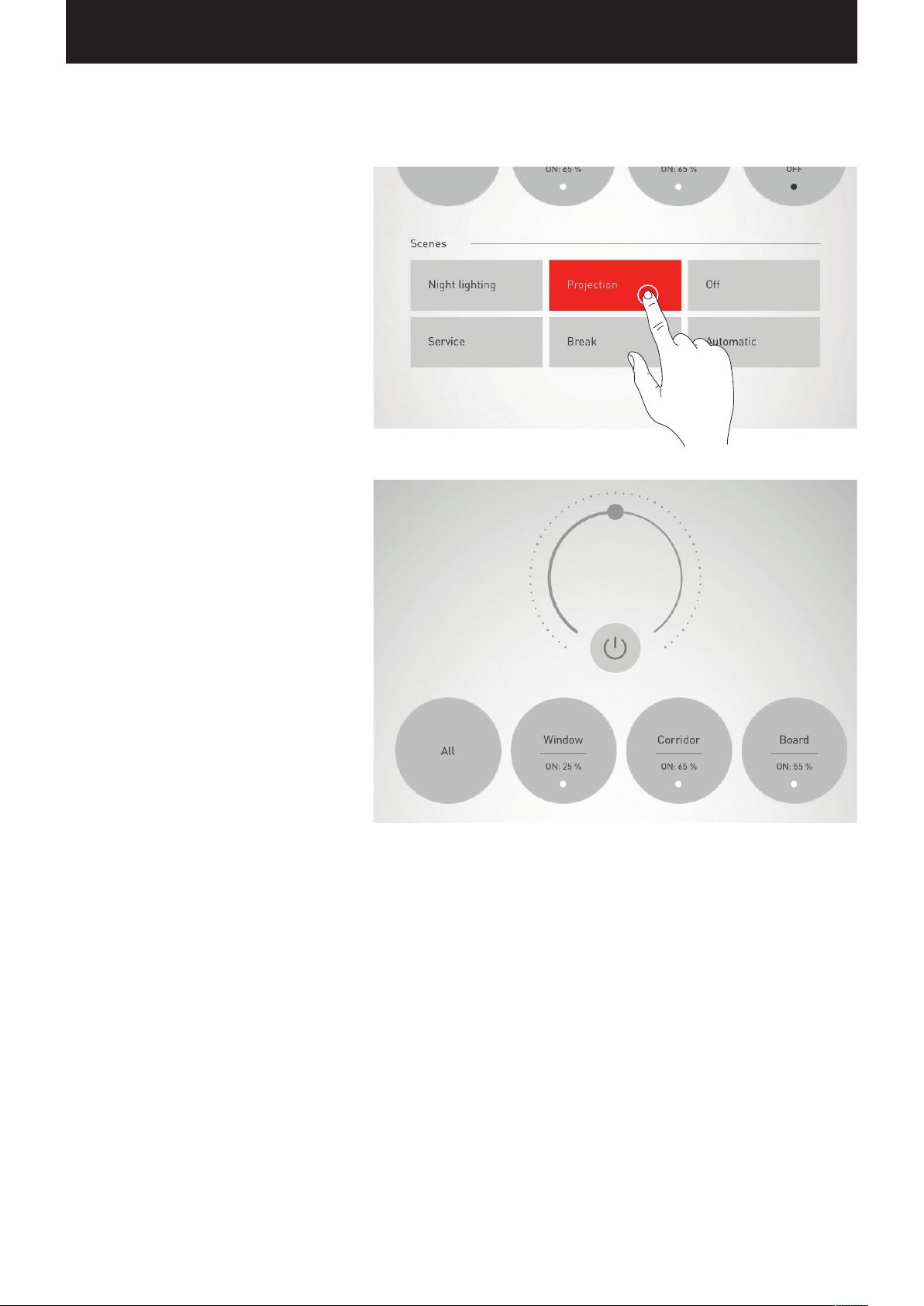
“LIVELINK CONTROL” APP / ACTIVATION OF ILLUMINATION SCENARIOS Page 73 / 77
ACTIVATION OF ILLUMINATION SCENARIOS
Previously created illumination scenarios can be
activated from the list in the lower area of the view.
The scene is activated by tapping on the respective line. It is provided with a red background and
marked with a check mark.
The current state of illumination is displayed; however, the operating fields of the manual light control
are depicted grey.
Once the illumination scenario has been activated, a
manual intervention can be carried out immediately; for this, see chapter “Manual setting of the room
illumination”.
Page 74

FAQ Page 74 / 77
FAQ
Where can I get the app?
How much does the app
cost?
Does anybody have access
to the app?
How do I receive updates
for the app?
Why is not WiFi symbol
displayed in the iOS app?
Where can I find the operating instructions?
Can I operate the system
via smart phone?
Can I program the system
via smart phone?
Is a DALI addressing
necessary for the group
assignment?
Is a commissioning necessary?
Is the system functional in
delivery condition?
What is needed for
commissioning?
Which Use Cases are
included with the system
upon delivery?
The app is available via the respective
AppStore of the system (Android or iOS).
The app is available free of charge.
Yes, the app can be downloaded by
anybody.
The updates for the app can be
retrieved via the respective AppStore.
A WiFi symbol is not displayed
because the system can neither
access a gateway nor a DNS server.
As such, an Internet connection is
possible for example via LTE.
A quick start guide is included in the
scope of delivery. Detailed operating
instructions (a system manual) are
available in the app as well as on
the TRILUX website. In addition, a
detailed description of the respective
screen can be retrieved in the app via
the “?” symbol.
Yes, there will be a user app, just for
operation.
The commissioning takes place via
the “Install” app, for which a tablet is
needed.
No, the system cannot be programme
with a smart phone. For the programming of the system, a tablet PC is
needed.
Operation via the user app is possible.
Yes, a DALI addressing of the
participants is necessary for the
group assignment. However, the
system automatically performs an
addressing via bus scan.
For the basic settings, no commissioning is necessary. (On/Off/Dimming)
For advanced functions such as a
grouping, daylight control, etc., a
commissioning via the “Install” app
must take place.
Yes, the system is functional in the
basic settings in delivery condition. (On/Off/Dimming)
The system can be adjusted to the
application as needed via the “Install”
app.
For commissioning, a tablet PC with
the app installed is needed.
LiveLink is delivered with a number
of standard Use Cases.
Most applications are covered with
these Use Cases.
Which manual settings
options are there on the
sensor?
Which settings options are
there on the sensor via the
software?
How large is the detection
area of the sensor?
How many sensors can be
connected to a system?
Which installation height
must be adhered to?
How long is the shut-off
delay?
Is a parallel operation of
multiple sensors possible?
Does the sensor count as a
DALI participant?
Can any sensor be
connected?
Does the sensor need a
mains power?
Where should the sensor
be positioned (close to
the window / far from the
window)?
For which areas of application are the sensors
planned for?
Which types of sensors are
being utilised?
Can the sensitivity and/
or range of the sensor be
adjusted?
The detection range of the Steinel
Quattro HD can be adjusted via a
small thumb wheel on the back of the
sensor.
Via the software, the shut-off delay
for the presence detection, the value
of the constant light control, and the
general detection area of the sensor
can be set.
The detection area depends on the
sensor type and height of installation
(the latter only applies to the corridor
sensor Dual HF).
For information, see data sheet
In a system, any number of sensors
can be connected. However, the
maximum number of 64 DALI participants may not be exceeded in this.
The height of installation depends
on the type of sensor. The LiveLink
controller should not be installed at
extreme heights since the WLAN has a
limited range (approx. 20-25 metres).
The shut-off delay can be set with the
help of the app. The maximum value
is 60 minutes.
Yes, a parallel operation of multiple
sensors is possible.
This setting is applied in the Use Case.
Yes, the sensor does count as a DALI
participant. Depending on the type
of sensor, one sensor may occupy
multiple DALI participants (the Steinel
corridor sensor Dual HF, for example,
occupies 7 DALI participants).
For sensor details, see the respective
data sheet
No, it is not possible to connect just
any sensor. The sensors must be
LiveLink-compatible.
No, the sensor receives power via the
DALI line.
The sensor should be positioned
where it receives an average intensity
of daylight, for example in the middle
of the room or near work spaces
to which the light control will be
calibrated.
The sensors are planned for presence
detection and constant light control.
At present, PIR and HF sensors are
being utilised.
The values for the corridor sensor
Dual HF can be adjusted via the app.
Page 75

FAQ Page 75 / 77
Can the dimming level in
case of switching off be
adjusted?
Can the value of the
daylight-dependent
control be adjusted?
How is the sensor
connected?
How many groups can be
controlled?
Which operating modes
are planned for?
What are DALI participants?
Do I need Internet access? For the commissioning and setup
Does a WLAN connection
have to be established?
Is the WLAN protected? Yes, the WLAN is encrypted based
Can the WLAN signal be
turned off?
How is the standby power
consumption?
Can the system be
installed in existing
systems?
What is a scene? A scene is a certain setting of the
What is the behaviour
upon PowerON?
Can an offset control be
realised?
How many push-buttons
can I connect to a pushbutton coupler?
No, the dimming level in case of
switching off cannot be adjusted.
Yes, the value can be adjusted via the
app in the sensor administration.
The sensor is connected via the DALI
line and does not require a separate
mains connection.
For additional information, see
sensor’s operating instructions
Up to 16 groups can be controlled.
The number of groups can be specified with the software for the creation
of the Use Cases.
The system can be operation manually, semi-automatically, or fully
automatically.
DALI participants are all those
components that can be addressed by
the LiveLink controller. These can, for
instance, be luminaires, sensors, or
push-button couplers.
of the system, no Internet access is
required. The system does independently create a WLAN to which
you have to connect. Internet access
is required only for downloading and/
or updating the app.
Yes, a WLAN connection to the
system must be established. The
system automatically creates a
WLAN to which you then only have to
connect in order to set up the system.
on the latest security standards. In
addition, the WLAN is protected via
a firewall on the LiveLink controller.
The apps also feature a secure password prompt. All data is transmitted
encrypted.
No, at present the WLAN signal
cannot be turned off.
The standby power consumption of
the controller is less than 2 watts.
LiveLink can be installed in an
existing DALI illumination system
but it must be ensured that no other
control system is connected to the
DALI bus.
luminaires and sensors in the room.
You can created multiple scenes and
switch between them with the help of
the app or of push-buttons.
LiveLink always calls up the default
scene first.
The default scene can be specified in
the app
Yes, an offset control can be realised
with LiveLink.
A maximum of 4 push-buttons can be
connected per push-button coupler.
Do I have to connect a
push-button coupler if I
only need a single pushbutton?
What does DALI mean? DALI (Digital Addressable Lighting
How many DALI participants can be connected?
Can a commercial pushbutton be connected for
manual operation?
How many push-buttons
can be connected?
How must the cabling be
performed?
Which line lengths may not
be exceeded?
Which line cross sections
must be adhered to?
Does the line have to be
voltage-proof?
Is the system reverse
polarity protected on the
DALI side?
Is the DALI input voltage-proof?
Can ballasts with 1-10 V
interface be connected?
Can ballasts with DSI
interface be connected?
Is there a minimum
distance between the
sensor and the LiveLink
controller that must be
adhered to?
A single push-button can be
connected directly to the LiveLink
controller. For this, terminal “S” on
the controller is planned for.
Interface) is an international
standard for building automation.
It is a protocol for the control of
photometric operating devices such
as switching mode power supplies
(“electronic transformers”), electronic ballasts (ECGs) or electronic
power dimmers.
Up to 64 DALI participants can
be connected. With the help of a
DALI repeater, more than 64 DALI
participants may also be connected;
these participants are, however, then
addressed as a group.
Yes, a commercial push-button can
be utilised for the manual operation of the system. The push-button
merely has to be connected to the
system via a push-button coupler.
The LiveLink controller is equipped
with one interface through which one
push-button can be connected. With
the help of one or more push-button
couplers, any number of push-buttons can be connected. However,
the maximum number of 64 DALI
participants may not be exceeded in
this. Up to four push-buttons can be
connected per push-button coupler.
The cabling is performed in linear,
start or tree form. A closed ring is not
possible!
Market-typical DALI line lengths
must be adhered to. These amount to
approx. 300 metres.
The line length between the pushbutton coupler and the LiveLink
controller may not exceed 25 metres.
0.5 - 1.5 mm²
Yes, the line must be voltage-proof.
(also DALI)
Yes, the system is reverse polarity
protected on the DALI side.
No, the DALI output is not voltage-proof
No, only DALI control gear can be
connected.
No, only DALI devices can be
connected.
Yes, a distance of at least 1 metre
between the LiveLink controller and
the sensor must be adhered to. If the
distance is too short, interference
may occur and thereby lead to false
reports by the sensor.
Page 76

FAQ Page 76 / 77
Page 77

TRILUX GmbH & Co. KG
Heidestraße · D-59759 Arnsberg
Postfach 19 60 · D-59753 Arnsberg
Tel. +49 29 32.3 01-0
Fax +49 29 32.3 01-3 75
[email protected] · www.trilux.com
TRILUX LlGHTING LlMITED
TRILUX HOUSE, Winsford Way
Boreham Interchange
Chelmsford, Essex
CM2 5PD
Tel. +44 12 45.46 34 63
Fax +44 12 45.46 26 46
[email protected] · www.trilux.com
10142279 / XI 15 (DE)
 Loading...