

Page 1

Orator
INTERCOM
Installation Guide
Issue 1.0
TRILOGY BROADCAST LIMITED
26 Focus Way
Walworth Estate
Andover
Hampshire
SP10 5NY
England
Telephone +44 (0) 1264 384000
Fax +44 (0) 1264 334806
Email [email protected]
Web site www.trilogy-broadcast.co.uk
Page 2

Orator Installation Guide
Page 2 of 37 Issue 1 Trilogy Broadcast Limited
Orator
The Copyright of the information and drawings in this
document is the property of Trilogy Broadcast Limited of
Andover, Hampshire and is neither to be reproduced in
whole or in part, nor disclosed to a third party, without the
prior written consent of Trilogy Broadcast Limited.
The information in this document has been carefully
compiled and checked for accuracy.
However, Trilogy Broadcast Limited accepts no
responsibility for inaccuracies which may occur and,
further, reserves the right to make changes to specification
or design without prior notice.
Comments or correspondence concerning this manual
should be addressed to The Design Manager at the
address given at the front of this User Guide.
DOCUMENT 45000660.doc ISSUE 1.0
Issue Date Reason for Change Approved
1 09 March 1999 First Issue for Internal Review
Page 3

Orator Installation Guide
Issue 1Trilogy Broadcast Limited Page 3 of 37
Orator
CONTENTS
1. INTRODUCTION.................................................................................................................................5
1.1 OPTIONS AVAILABLE AND MODULE TYPE NUMBERS .............................................................................5
2. INSTALLATION ..................................................................................................................................7
2.1 INTRODUCTION ....................................................................................................................................7
2.2 UNPACKING.........................................................................................................................................7
2.3 RACK MOUNTING................................................................................................................................. 7
2.4 MAINS CONNECTION AND FUSING......................................................................................................... 8
2.5 EARTHING REQUIREMENTS...................................................................................................................8
2.6 STARTING THE SYSTEM......................................................................................................................... 8
2.7 TEST CONFIGURATION..........................................................................................................................8
3. CONNECTING TO THE MATRIX...................................................................................................11
3.1 CONNECTING THE PORTS.................................................................................................................... 11
3.2 CONNECTING THE PC TO THE ORATOR SYSTEM................................................................................... 11
3.2.1 Connection via a PC COM port using RS232 protocol...............................................................11
3.2.2 Installing a CardPort ISA to PCMCIA adaptor into a desktop PC..............................................12
3.2.3 Installing a PCMCIA download card in a laptop computer ........................................................ 12
3.2.4 Installing PathFinder Lite ......................................................................................................... 13
3.3 OTHER CONNECTIONS ........................................................................................................................14
3.3.1 Matrix Ports..............................................................................................................................14
3.3.2 Camera Connector....................................................................................................................14
3.3.3 Alarms...................................................................................................................................... 15
3.3.4 Serial Link ................................................................................................................................ 15
3.3.5 20M bit/S Link ..........................................................................................................................16
3.3.6 GPI O Connector...................................................................................................................... 17
3.3.7 Beltbox .....................................................................................................................................18
4. CONTROL PANELS ..........................................................................................................................19
4.1 STANDARD CONTROL PANELS ............................................................................................................19
4.1.1 500-30 Series Standard Control Panel Rear View...................................................................... 20
4.1.2 500-30 Series Control Panel Connections.................................................................................. 20
4.1.3 500-30 Series DIP Switch Settings.............................................................................................21
4.2 500-39-30 / 31 1U 12 KEY STANDALONE PANEL WITH LOUDSPEAKER..................................................22
4.2.1 Connector Pin Out....................................................................................................................22
500-39-30 Rear View............................................................................................................................. 23
4.3 500-41 SERIES DESKTOP PANELS ........................................................................................................ 24
4.4 500-40 SERIES EXPANSION PANELS .................................................................................................... 25
4.4.1 Connector Pin Out....................................................................................................................25
4.4.2 500-40 Series Control Panel Rear View.....................................................................................26
4.4.3 Typical expansion panel configuration ......................................................................................27
4.4.4 Expansion panel interconnection cables .................................................................................... 29
4.5 CONNECTING VIA STRUCTURED CABLING ............................................................................................ 29
5. OTHER EQUIPMENT .......................................................................................................................31
5.1 BELT BOXES ......................................................................................................................................31
5.2 TELEPHONE INTERFACES.................................................................................................................... 32
5.3 RT EQUIPMENT.................................................................................................................................. 33
5.4 ISDN INTERFACE (500-22-00)............................................................................................................33
5.4.1 ISDN Interface Connector Pin-Outs ..........................................................................................34
5.4.2 Notes ........................................................................................................................................ 34
6. SPECIFICATION ...............................................................................................................................35
6.1 GENERAL........................................................................................................................................... 35
6.2 MATRIX AUDIO SPECIFICATION .......................................................................................................... 35
6.3 REAL TIME PERFORMANCE ................................................................................................................. 35
6.4 PANELS..............................................................................................................................................35
6.5 GPIO SPECIFICATION ......................................................................................................................... 36
Page 4

Orator Installation Guide
Page 4 of 37 Issue 2 Trilogy Broadcast Limited
Orator
6.6 P.C....................................................................................................................................................36
6.7 INTERNAL PANEL SWITCH SETTINGS ...................................................................................................37
6.8 500-41 DESKTOP PANEL INTERNAL SETTINGS .....................................................................................37
Page 5

Orator Installation Guide
Issue 1Trilogy Broadcast Limited Page 5 of 37
Orator
1. INTRODUCTION
This manual provides installation information for the Orator Digital Intercom system. Cabling
and pin-out information is included for all of the Trilogy manufactured items plus some
commonly used third party equipment. Other information relating to the hardware
configuration will be useful if the system is upgraded or expanded in the future.
Ø Section 2 covers the matrix assembly and installation, to the point where the matrix may
be powered
Ø Section 3 covers all of the cabling necessary to complete the installation.
Ø Section 4 gives wiring details for the range of Trilogy control panels.
Ø Section 0 provides Information on installing other equipment (e.g. telephones, radio
talkback).
For further assistance please contact Trilogy Broadcast Projects Department at the address
given at the front of this document. You may also contact us by e-mail at:
1.1 Options Available and Module Type Numbers
Contact Sales Department for a listing of the current module types.
Due to the nature of talkback systems, any given installation may have some custom parts.
Trilogy Broadcast Ltd. prides itself on its ability to tailor standard parts to meet specific
requirements and is willing to discuss any other customisation as required.
Page 6

Orator Installation Guide
Page 6 of 37 Issue 2 Trilogy Broadcast Limited
Orator
Page 7
Orator Installation Guide
Issue 1Trilogy Broadcast Limited Page 7 of 37
Orator
2. INSTALLATION
2.1 Introduction
Follow the sequence below, step by step, to install the Orator matrix.
Ø Unpack the matrix
Ø Fit the matrix frame into the equipment bay
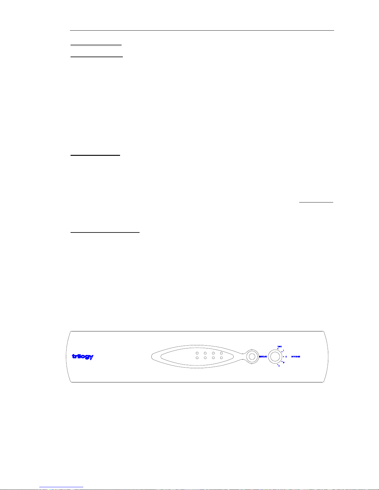
Ø Set the database selector switch on the front panel to “Test”
Ø Apply power to the system and check basic operation.
Ø Connect control panels and check operation with the pre-loaded flash ram configuration.
Ø Set up the configuration PC.
2.2 Unpacking
Carefully unpack the equipment from its transit material and check each item for any signs of
damage.
Check the contents of the boxes against our despatch note and your original order to ensure
that you have received the correct parts.
In the event that the unit has been damaged or does not match your order, immediately
contact Trilogy Broadcast Ltd. at the address given at the front of this guide.
2.3 Rack Mounting
The Orator Matrix occupies 2U of rack space. The depth (excluding mating connectors) is
370mm (15"). Control Panels are standard 425mm (19”) rack-mounting units; most panels
are 2U although a series of 1U panel are available and custom panels may be 3U, 4U or
larger.
It is most likely that a system contractor or Trilogy personnel will install the central matrix.
Suitable care should be taken with cooling and ventilation within the equipment bay.
Page 8
Orator Installation Guide
Page 8 of 37 Issue 2 Trilogy Broadcast Limited
Orator
2.4 Mains Connection and Fusing
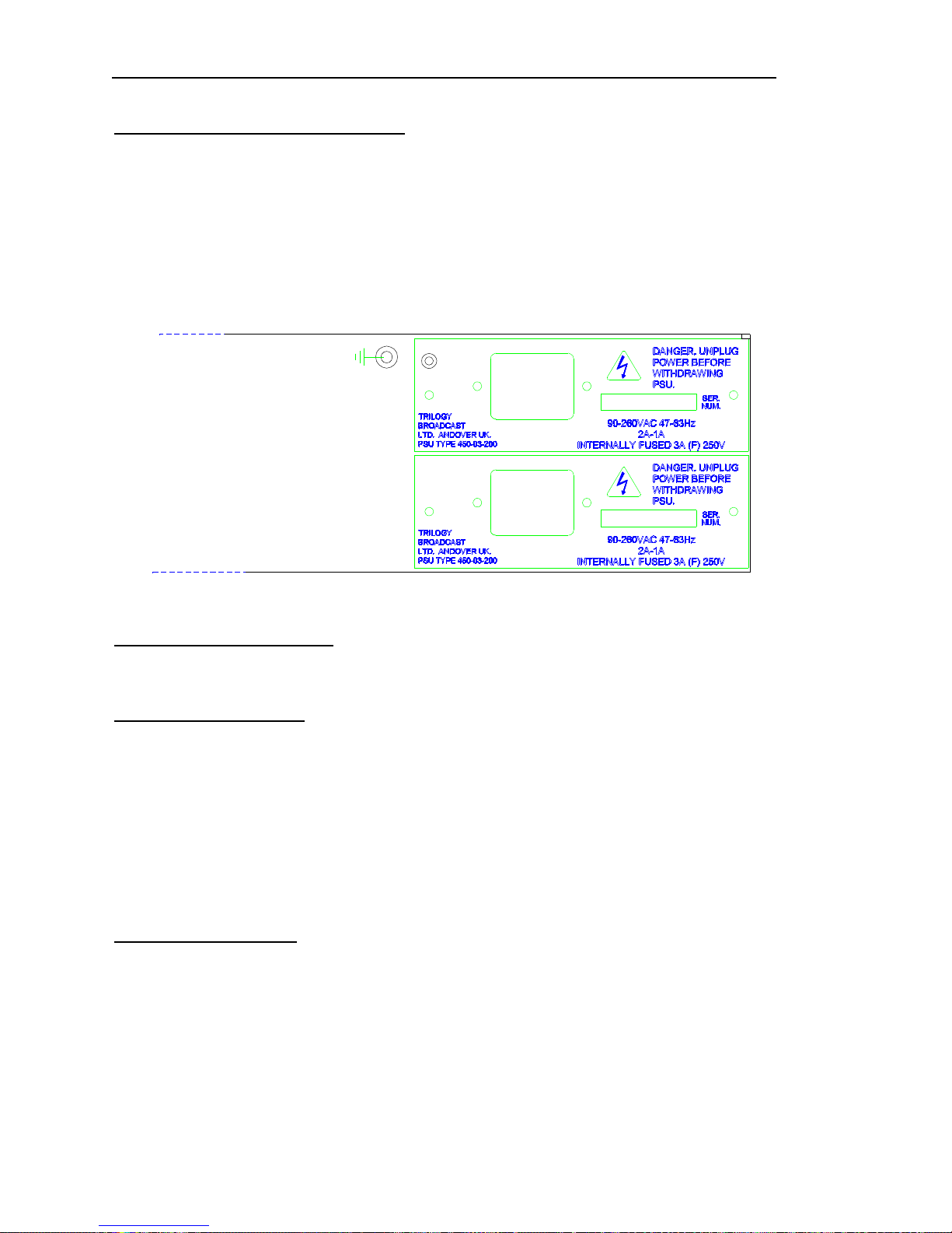
The Orator matrix operates from a single power supply, although an optional second power
supply may be fitted to provide full redundancy. This may be purchased and fitted later if
required.
The power supplies are fitted from the rear of the matrix and fixed with retaining screws.
If the second power supply is not fitted, a blanking plate covers the space at the back of the
matrix.
2.5 Earthing Requirements
A 4mm stud is provided on the rear panel of the matrix for connection to a local technical
earth. For safety reasons, the unit should be earthed at all times
2.6 Starting the system
The system may now be powered and will load a configuration from the Flash RAM. The
rotary switch selects the boot configuration bank. It is not necessary to have the computer
operating at this stage.
--------------------------------------------------------------------------------------------------------------------------Tip: When the switch is set to position TEST, a default simple configuration is loaded from
flash RAM. See below.
---------------------------------------------------------------------------------------------------------------------------
2.7 Test Configuration
A simple test configuration is “hard-coded” into the system software and cannot be erased.
Connect control panels to Ports 1 and 2 using the supplied leads, as described in the Quick
Start Guide included with the system.
This configuration can be used to prove the basic system functionality.
Page 9

Orator Installation Guide
Issue 1Trilogy Broadcast Limited Page 9 of 37
Orator
As the system is powered, all front panel LEDs are lit briefly. Under normal operating
conditions, the LEDs are lit as detailed in the following table.
Phase LED Colour Status
POWER UP COMMS YELLOW ON
POWER A BLUE ON If present
POWER B BLUE ON If present
AUDIO 1 OK GREEN OFF If present
AUDIO 2 OK GREEN OFF If present
FAULT RED ON briefly
NORMAL COMMS YELLOW FLASHING
POWER A BLUE ON If present
POWER B BLUE ON If present
AUDIO 1 OK GREEN If present
AUDIO 2 OK GREEN If present
FAULT RED ON briefly
PROBLEM
(System Failure) FAULT RED ON other LED states indeterminate
PROBLEM FAULT RED OFF
(Audio Failure) AUDIO 1 OK GREEN FLASHING Alarm will trigger
AUDIO 1 OK GREEN FLASHING Alarm will trigger
PROBLEM FAULT RED OFF Alarm will trigger
(Power Failure) POWER A BLUE OFF Alarm will trigger
POWER B BLUE OFF Alarm will trigger
Page 10
Orator Installation Guide
Page 10 of 37 Issue 2 Trilogy Broadcast Limited
Orator
Page 11

Orator Installation Guide
Issue 1Trilogy Broadcast Limited Page 11 of 37
Orator
3. CONNECTING TO THE MATRIX
3.1 Connecting the Ports
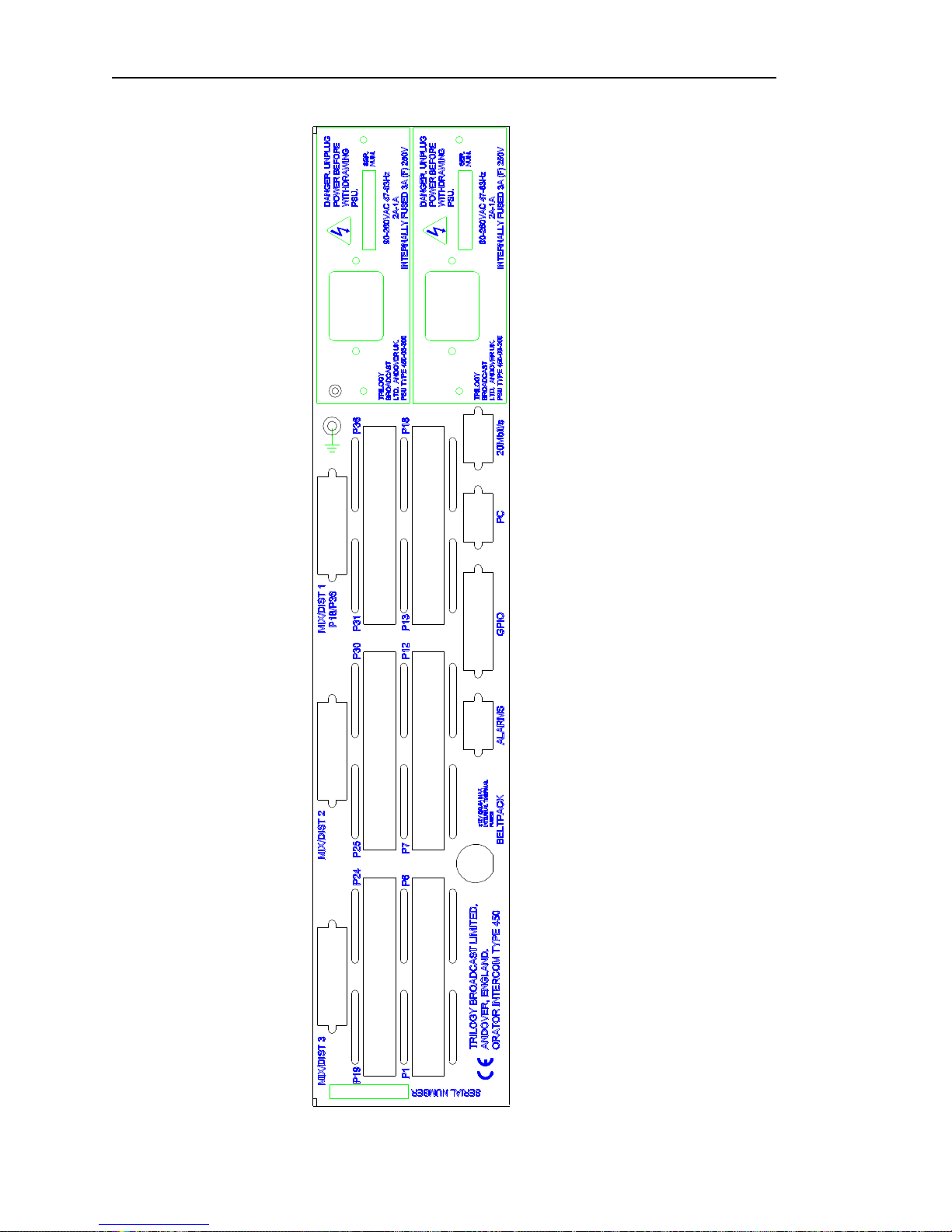
The drawing on page 10 shows the rear view of the Orator central matrix. Connectors are
provided for:
Ø 18 or 36 matrix ports, either 4-wire or panel
Ø The configuration PC
Ø Logic connections (GPI and GPO) input and output
Ø A 20MB/S data link, primarily for use by Trilogy staff for system testing
Ø Optional multi way camera connections
Ø Pre-configured beltpack connector
These are covered in more detail in the following sections. Where appropriate, the connector
type, denoted by male or female, refers to the fixed connector on the rear of the equipment.
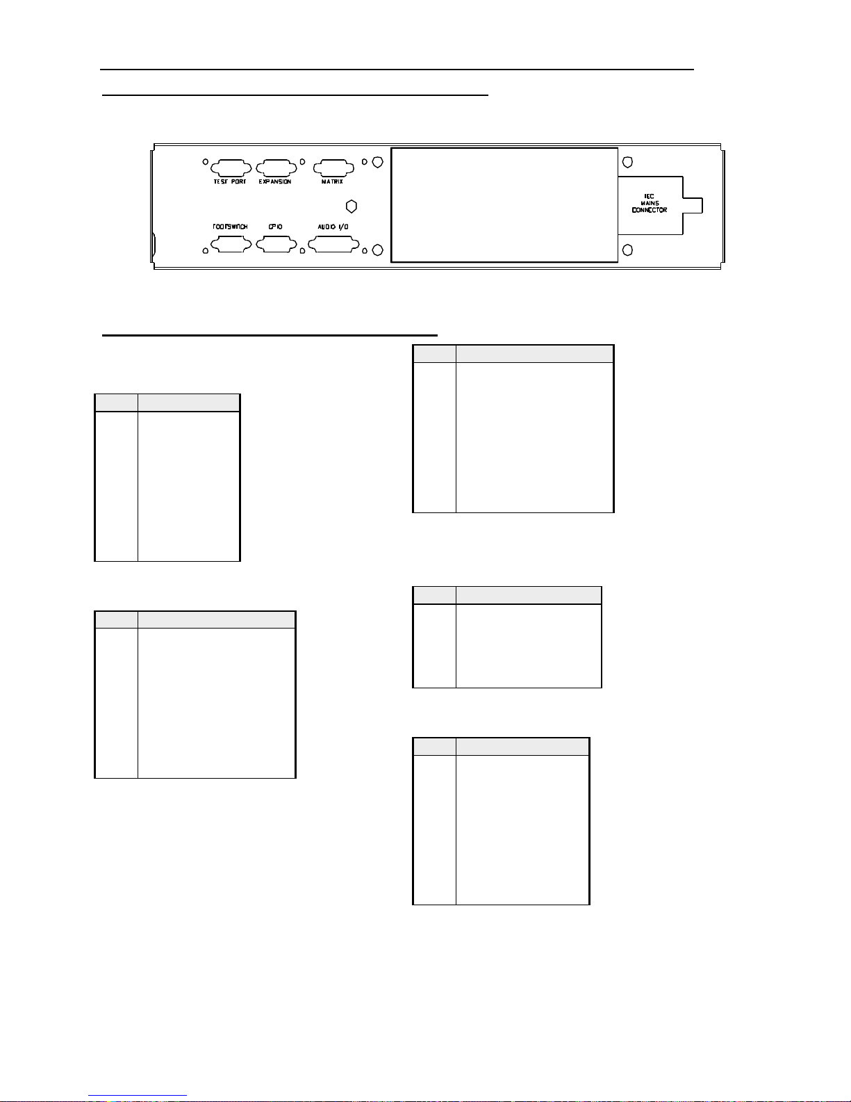
The diagram opposite shows the location of all connectors on the rear panel.
3.2 Connecting the PC to the Orator System
A number of different options are available, depending on the type of computer which will be
used. These are:
Ø RS232 serial link, direct from a standard PC COM port. See Section 3.2.1 for more
detail.
Ø A desktop PC fitted with a CardPort ISA to PCMCIA carrier and a Sundance card as
below. See Section 3.2.2.
Ø A laptop PC fitted with a Sundance SMT104 PCMCIA style adaptor card. See Section
3.2.3.
Connect the PC to the 9 way D type plug labelled "20MB/s PC link" on the rear right side of
the matrix. In a multi-frame system (i.e. >96 ports) the PC may be connected to any of the
available PC connectors but we would recommend frame 1 as the default. Initially, we
suggest establishing control of the system using the supplied cable.
3.2.1 Connection via a PC COM port using RS232 protocol
Connect the Orator matrix to the PC COM port with a 9 way D-type cable A 2 metre cable is
supplied with the unit. If the PC has a 25 way D-type COM port, fit the adaptor supplied.
To use the RS232 downloas facility, start PathFinder and use the Options : Settings menu
form to select the serial download option. Select the relevant PC COM port: all other settings
are automatically adjusted.
Page 12

Orator Installation Guide
Page 12 of 37 Issue 2 Trilogy Broadcast Limited
Orator
3.2.2 Installing a CardPort ISA to PCMCIA adaptor into a desktop PC
The CardPort adaptor will normally be supplied by Trilogy although similar units by other
manufacturers are available. Comprehensive instructions are included with the CardPort unit
but the list below provides a summary. You will require access to the Windows 95/98
installation media (floppy disks or CD).
Ø Switch off the PC and remove the cover.
Ø Fit the CardPort adaptor into a free ISA slot.
Ø Re-start the PC
Ø From the Start menu, select Settings >> Control Panel >> Add New Hardware. The "Add
New Hardware Wizard" now appears.
Ø Choose the option to "Specify the type of hardware" and pick "PCMCIA socket" from the
list.
Ø Now choose a Manufacturer (Standard PCMCIA driver) and Model (PCIC or compatible).
This completes the first phase. The PC card wizard will now start, allowing the easy removal
of any existing DOS or Windows 3.1 drivers, which may be present on your PC. Read the
prompts carefully. In most cases with modern hardware it will be safe to answer "No" to the
first question. Once any 16 bit drivers have been removed, you will be prompted to shut
down and completely turn off your PC.
If you now intend to install the SMT104 Transputer adaptor, fit the PCMCIA card into the
adaptor prior to switching the PC back on. Follow the instructions in Section 3.2.3 below.
3.2.3 Installing a PCMCIA download card in a laptop computer
The Trilogy part number for the PCMCIA link adaptor card is 500-16-01. It is supplied with a
short link cable, which may be extended as necessary to a suggested maximum of 5 metres
of RS422 cable. The card can be fitted in a PCMCIA slot, on a laptop PC running Windows
95/98 or into the CardPort adaptor on a desktop PC if appropriate. Windows 95 will normally
detect the addition of new hardware when the system is re-booted and prompt for the
manufacturers’ disk. The original manufacturer is Sundance, and the card is type SMT104.
If the card is being installed into a brand new laptop PC the PCMCIA support must be
enabled according to the manufacturers' instructions.
On re-booting the PC with the link adaptor card fitted, follow this sequence:
Ø Windows should now detect "Applied Transputer Ltd. ATT PC 8004 PCMCIA"
Ø Select the option "Install driver from disk provided". Insert the supplied disk and press
Enter.
Ø A PCMCIA icon should now appear on the taskbar at the lower right of screen.
Ø Finally, from the Start menu, select Settings >> Control Panel >> System >> Device
Manager to check for system conflicts indicated by a yellow ! symbol. The default base
address adopted by the link adaptor card to 150 which matches PathFinder Lite
software. Any hardware address changes must be matched by corresponding changes
to the PathFinder Lite set-up. See section for further details.
Page 13
Orator Installation Guide
Issue 1Trilogy Broadcast Limited Page 13 of 37
Orator
3.2.4 Installing PathFinder Lite
Software is supplied on CD-ROM but is also available on 3.5" floppy or by download from
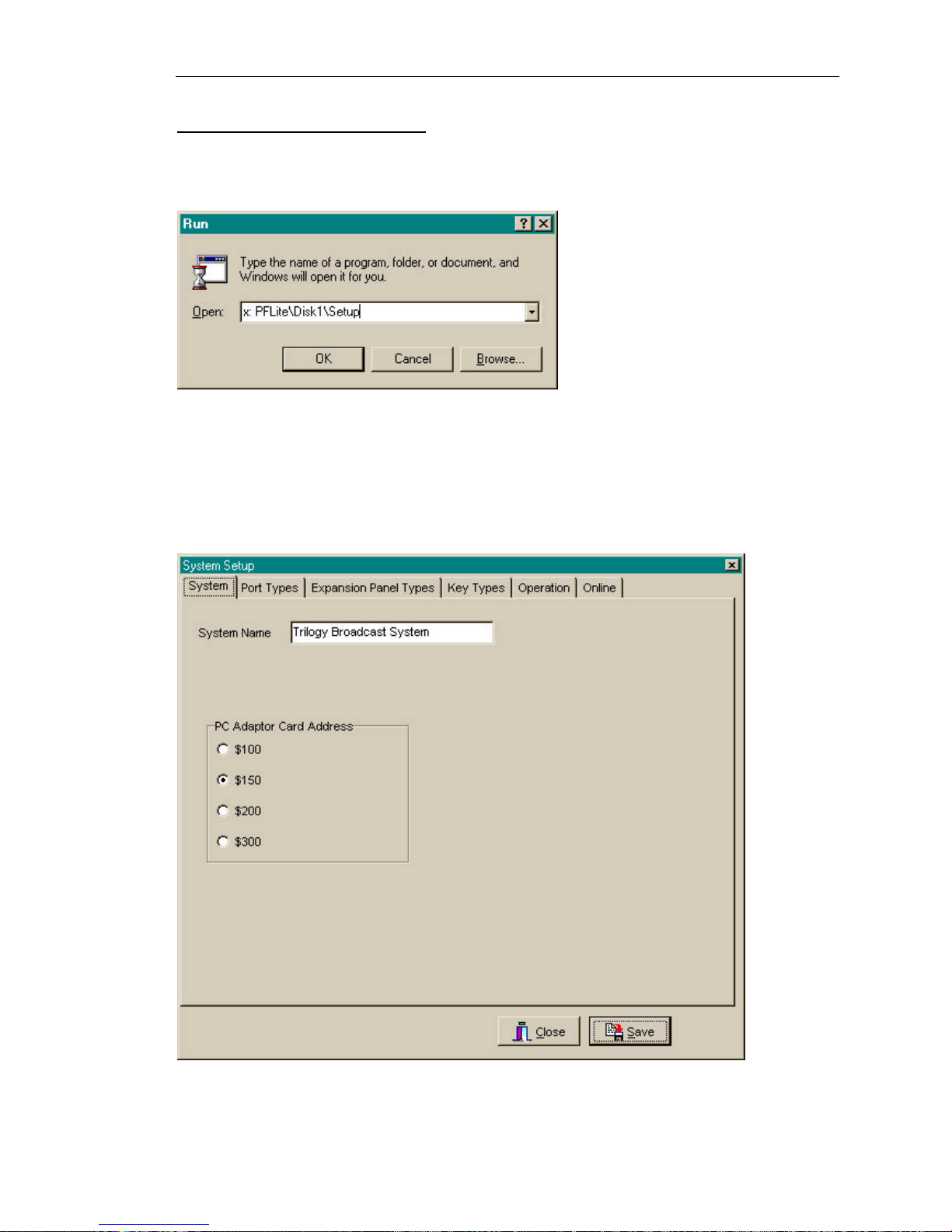
the Trilogy web-site by prior arrangement. To install from CD-ROM, follow the instructions
below.
Click Ok then follow the on-screen prompts. When the software installation is complete, the
PathFinder Lite icons will be visible in a folder on the desktop.
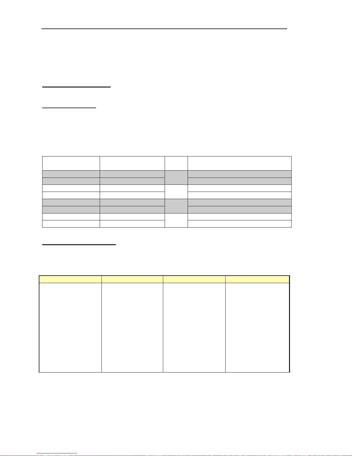
Start PathFinder Lite, following the options to create a New Database. From the Options pull
down menu, select Settings and the dialogue box shown below will be displayed.
Any changes made to the settings only take effect when PathFinder Lite is re-started.
A warning dialogue box is displayed when the settings dialogue box is closed.
Page 14
Orator Installation Guide
Page 14 of 37 Issue 2 Trilogy Broadcast Limited
Orator
This allows system name and PC Adapter Address to be changed. Changes to the PC card
adapter address will only be required if there is a hardware clash with other PC devices such
as a sound card or CD-ROM. Any changes within PathFinder Lite must be matched by
changes to the adapter card itself.
Make the necessary changes to the System settings, to match hardware and software
parameters. Save the Settings, then close and re-start PathFinder Lite.
3.3 Other Connections
A number of other connections are provided on the rear of the matrix.
3.3.1 Matrix Ports
The same connector pin-out applies to ports used for panels or externals. External (4-wire)
connections will not use the data pairs. Cable is quad twisted 100Ω pair, with overall screen.
Although STP cables are recommended for longer cable runs, UTP cable will be acceptable
for cable runs of <50 metres. See Specification for maximum cable length. We suggest a
CAT 5 type cable, from a recognised supplier such as Beldon.
Connector type: RJ45 chassis socket
Pin Function Notes
1 Matrix Data in + Only applies to ports used for panels
2 Matrix Data in -
Pair 1
Only applies to ports used for panels
3 Matrix Data out + Only applies to ports used for panels
6 Matrix Data out-
Pair 2
Only applies to ports used for panels
5 Matrix Audio in +
4 Matrix Audio in -
Pair 3
7 Matrix Audio out +
8 Matrix Audio out -
Pair 4
3.3.2 Camera Connector
This option provides a mixing pad for up to 6 camera inputs, and a single feed for audio
connection to cameras.
Connector type: 25 way D type fixed socket.
D-25 PIN FUNCTION D-25 PIN FUNCTION
1 SCREEN/CHASSIS
2 FROM CAM 1+ 14 FROM CAM 13 FROM CAM 2+ 15 FROM CAM 24 FROM CAM 3+ 16 FROM CAM 35 FROM CAM 4+ 17 FROM CAM 46 FROM CAM 5+ 18 FROM CAM 57 FROM CAM 6+ 19 FROM CAM 68 TO CAM 1+ 20 TO CAM 1-
9 TO CAM 2+ 21 TO CAM 210 TO CAM 3+ 22 TO CAM 311 TO CAM 4+ 23 TO CAM 412 TO CAM 5+ 24 TO CAM 513 TO CAM 6+ 25 TO CAM 6-
Page 15

Orator Installation Guide
Issue 1Trilogy Broadcast Limited Page 15 of 37
Orator
3.3.3 Alarms
The output is a normally made solid state relay contact. Maximum current rating is 120mA.
Connector type; 9 way D type fixed socket.
Pin Function
1 PSU FAIL+
6 PSU FAIL 2 PSU FAIL+
7 PSU FAIL 3 PSU FAIL+
8 PSU FAIL 4 PSU FAIL+
9
5
3.3.4 Serial Link
The serial port may be configured internally as RS422 or RS232. As supplied, the system is
configured for RS232 operation. The tables below show the alternative pin-out.
Connector type: 9 way D type fixed socket
RS422 configuration
Pin Function Notes
4,8 422 In +,6,1 422 Out +,5,9 422 CTS +,3 Chassis
RS232 configuration
PC COM PORT ORATOR SIGNAL
9 Pin
Female
25 Pin
Female
9 Pin
Female
1 8 1 DCD
2 3 2 TX
3 2 3 RX
4 20 4 DTR
5 8 5 0V or GND
6 6 6 DSR
7 4 7 CTS
8 5 8 RTS
9 DTR+DSR+DCD 9 RI
CASE 1
Page 16

Orator Installation Guide
Page 16 of 37 Issue 2 Trilogy Broadcast Limited
Orator
3.3.5 20M bit/S Link
Connector type: 9 way D type fixed plug
Pin Function
1 Error Out
6 CPU Analyse
2 N Test
7 N Reset
3 Ground
8 From PC4 From PC+
9 To PC5 To PC+
Page 17
Orator Installation Guide
Issue 1Trilogy Broadcast Limited Page 17 of 37
Orator
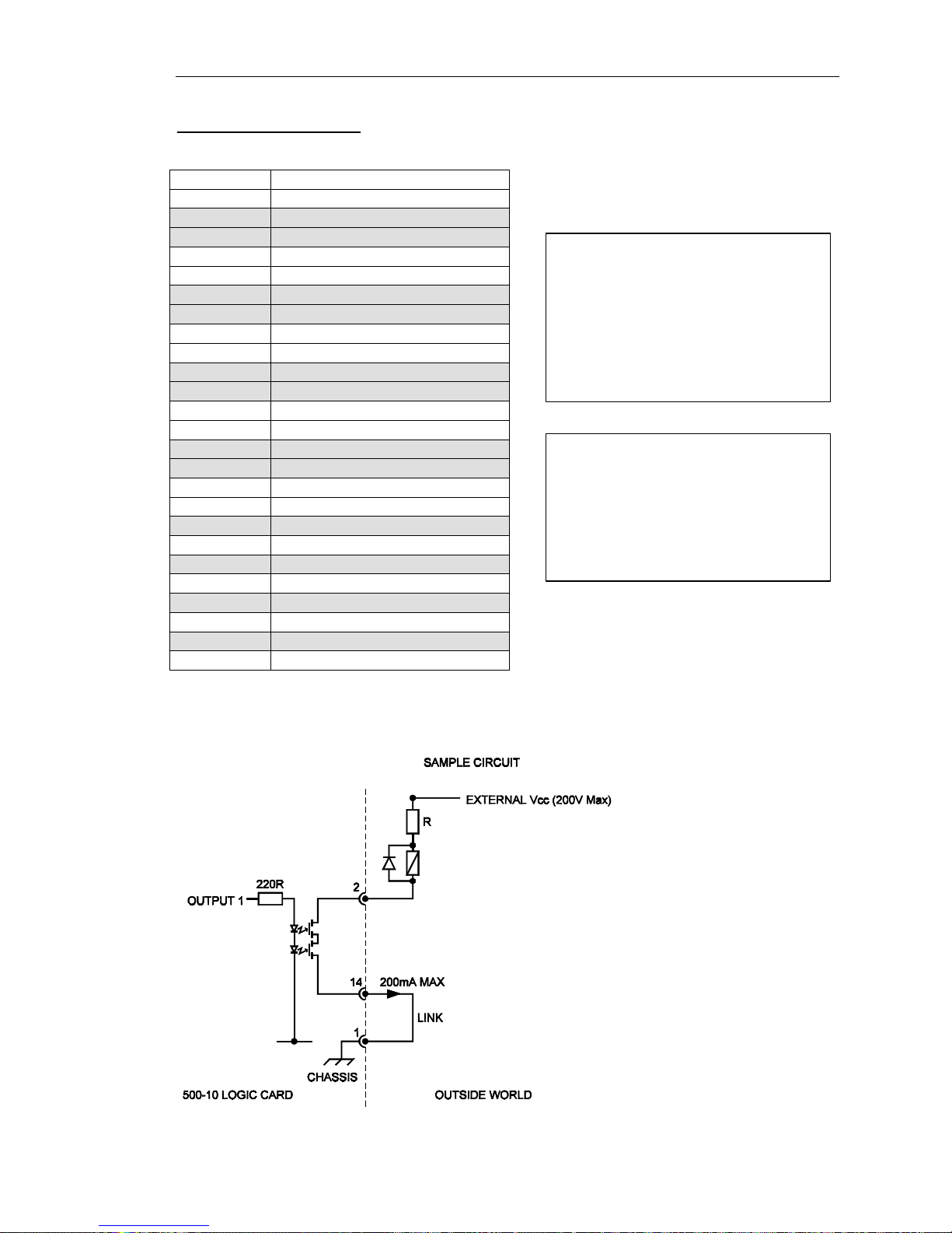
3.3.6 GPI O Connector
Connector: 25 way D type fixed socket.
Pin Number Function
1 GROUND
14 Output 1+
2 Output 115 Output 2+
3 Output 216 Output 3+
4 Output 317 Output 4+
5 Output 418 Output 5+
6 Output 519 Output 6+
7 Output 620 Output 7+
8 Output 721 Output 8+
9 Output 822 Input 1
10 Input 2
23 Input 3
11 Input 4
24 Input 5
12 Input 6
25 Input 7
13 Input 8
The circuit below shows suggested
wiring for Output 1 of the Orator
Logic facilities Maximum current
through the output stage must be
limited to 200mA and the maximum
permitted external voltage is +200V.
If these limits are exceeded, the
card may be damaged.
To activate a logic input, connect the
relevant logic input pin to ground. A
typical example of the external
circuitry for the logic outputs is
shown below.
Page 18

Orator Installation Guide
Page 18 of 37 Issue 2 Trilogy Broadcast Limited
Orator
3.3.7 Beltbox
Connector type: 12 way Hirose fixed plug
Pin Number Function
1 Chassis (cable screen)
2 Main audio + (PTB) to beltpack
3 Main audio - (PTB) to beltpack
4 Audio 2+ (Prog Snd) to beltpack
5 Audio 2- (Prog Snd) to beltpack
6 Audio + from beltpack
7 Audio - from beltpack
8 +12V to beltpack
9 -12V to beltpack
10 0V to beltpack (not cable screen!)
11 Audio 3+ to beltpack
12 Audio 3- to beltpack
The Beltbox connector is connected internally to the ports shown in the above table, so the
configuration generated in PathFinder Lite must match this to ensure correct operation.
Page 19
Orator Installation Guide
Issue 1Trilogy Broadcast Limited Page 19 of 37
Orator
4. CONTROL PANELS
All control panels connect to the matrix in point to point topology. Each panel utilises a single
matrix port, although expansion panels may be connected to a single “master” panel using
the expansion in and expansion out connectors fitted on the rear of the panel. Two standard
panels may be linked together, for example to provide 48 keys for an operator, but only
utilising a single matrix port. A series of additional connectors provide the following facilities,
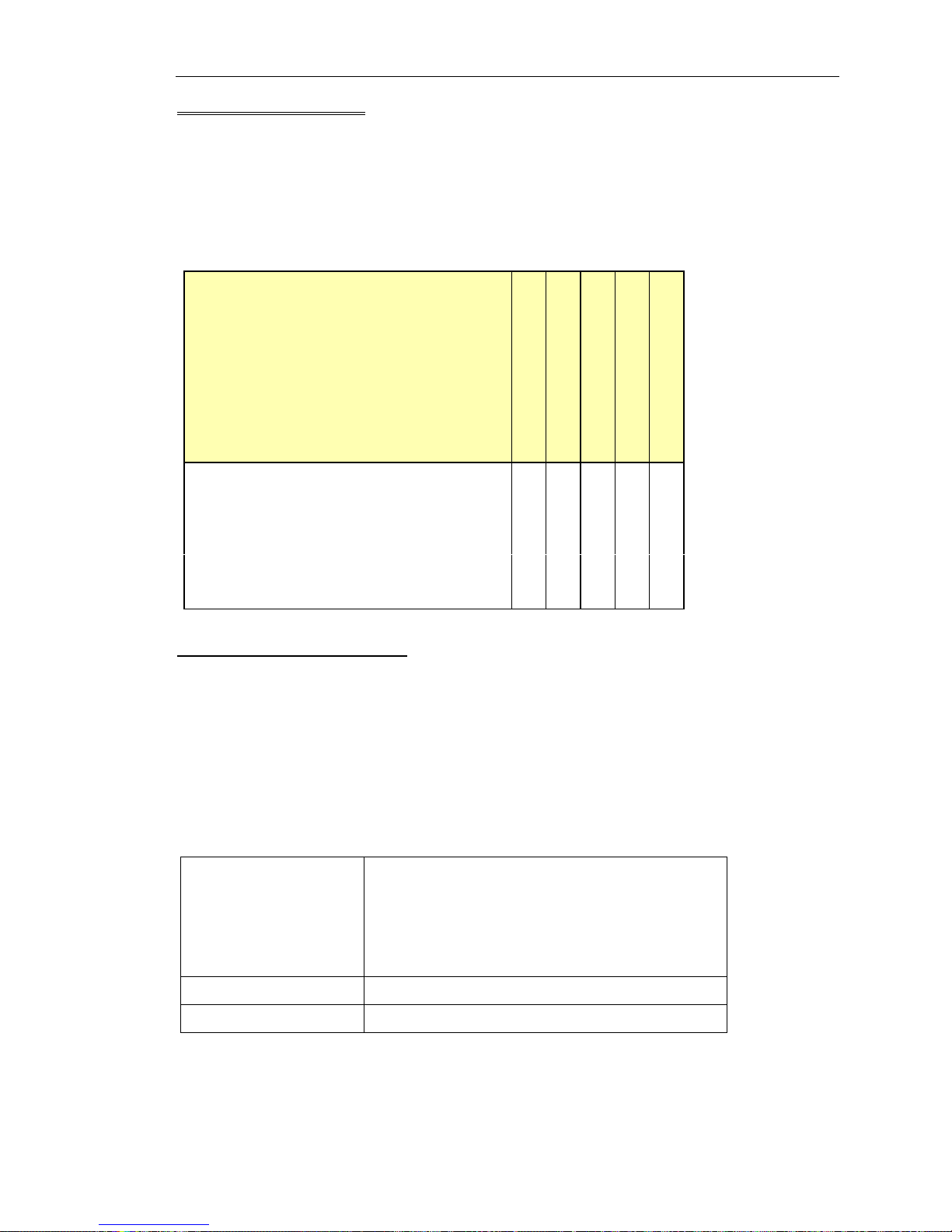
on the panel types indicated in the table.
Standard 8/16/24
1RU 12 key
1 RU 12 key + expansion
Desktop
Expansion Panel
Comprehensive audio inputs and outputs
√ √ √
Expansion ports 1 2 2
Local logic inputs and outputs
√
Test Port for re-programming
√ √ √ √
Remote control footswitches
√
4.1 Standard Control Panels
The following detail refers to these panel types:
Ø 500-30-30 24 key panel
Ø 500-31-30 16 key panel
Ø 500-31-31 16 key panel with dial pad
Ø 500-32-30 8 key panel
Ø 500-32-31 8 key panel with dial pad
Dimensions 485mm wide x 88.9mm high x 80mm deep
(max, excluding connectors). Approx. 110mm
deep ( max including mating connectors)
19” x 2RU rack mounting
Mains Input 90 – 250 V ac, 50-60Hz
Current Consumption 150-50 mA
Details of panel connections are provided in the following tables. Other features may be
enabled or disabled by the DIP switches accessible at the top of the panel. These are
detailed in section 4.1.3.
Page 20
Orator Installation Guide
Page 20 of 37 Issue 2 Trilogy Broadcast Limited
Orator
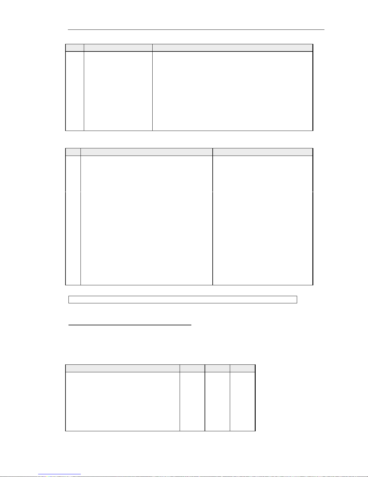
4.1.1 500-30 Series Standard Control Panel Rear View
4.1.2 500-30 Series Control Panel Connections
Matrix – 9D Fixed Plug
Pin Function
1 NC (Screen)
2 Data Out3 Data In4 Audio Out5 Audio In6 Data Out+
7 Data In+
8 Audio Out+
9 Audio In+
Test Port– 9D Fixed Socket
Pin Function
1 Analyse Input
2 Enable Remote Boot
3 Ground
4 Transputer Link Out+
5 Transputer Link In+
6 Error signal Out
7 Reset In
8 Transputer Link Out9 Transputer Link In-
Expansion Port– 9D Fixed Socket
Pin Function
1 Analyse Input
2 Enable Remote Boot
3 Ground
4 Transputer Link Out+
5 Transputer Link In+
6 Error signal in
7 Reset Out
8 Transputer Link Out9 Transputer Link In-
Headset - 5 Pin XLR Fixed Socket
(Front panel)
Pin Function
1 Mic IN (Screen)
2 Mic IN
3 Headset Gnd
4 Headset Out
5 Headset Out
Foot Switch - 9D Fixed Socket
Pin Function
1 Foot Switch Input
2 No Connection
3 Chassis Ground
4 No Connection
5 No Connection
6 Ground
7 No Connection
8 No Connection
9 No Connection
Page 21
Orator Installation Guide
Issue 2Trilogy Broadcast Limited Page 21 of 37
Orator
GPIO (Local logic in and out) - 9D Fixed Socket
Pin Function Notes
1 Ground
2 Logic Input 1
3 Logic Input 2
4 Logic 2 Out Common
5 Internal +5V (Out) Protected with series 44R & 1N4002 diode.
6 Logic Output 1
7 Logic 1 Out Common
8 Logic Output 2
9 Logic Input +VCC NB Pin 9 may be driven by external voltage (With
dropper resistor if greater than 5V), or by internal +5V
via pin 5.
Audio I/O – 15D Fixed Socket
Pin Function Notes
1 Slave Mic Input Line level, un-balanced
2 +15V Out (for slave mic panel) NOT protected!
3 Clean Mic Out + Line level, balanced, pair with 11
4 Ext CUT Input (for slave mic panel) Parallel function to front panel Cut
Switch. Ground to activate
5 Chassis Ground
6 No connection
7 External Input to LS Amp - Line level, balanced, pair with 14
8 Matrix Audio Input to Panel / parallel output - Line level, balanced, pair with 15
9 Ext Mic Cut output (to slave panel) Normally grounded. O/P is open
circuit when front panel cut
selected.
10 -15V Out (for Slave mic panel) NOT protected
11 Clean Mic Out - Line level, balanced, pair with 3
12 Mic Ground
13 Loudspeaker Output 8 ohm loudspeaker
14 External Input to LS Amp + Line level, balanced, pair with 7
15 Matrix Audio Input to Panel / parallel output + Line level, balanced, pair with 8
NB 15V supplies are also used to derive 12V for panel. (Thermally Fused @ 0.7A)
4.1.3 500-30 Series DIP Switch Settings
Within the panel a series of DIP switches determine the correct panel type. These are
factory set and are included for reference in Appendix 1.
A further set of DIP switches are user accessible at the top side of the panel and control the
action of the front panel CUT switch.
Cut Switch Action DIP 1 DIP 2 DIP 3
No action OFF OFF OFF
Changeover to HSet MIC ON OFF OFF
LS cut OFF ON OFF
Changeover to HSet MIC and LS cut ON ON OFF
MIC cut OFF OFF ON
Changeover to HSet MIC and MIC cut ON OFF ON
LS cut and MIC cut OFF ON ON
Everything ON ON ON
Page 22
Orator Installation Guide
Page 22 of 37 Issue 2 Trilogy Broadcast Limited
Orator
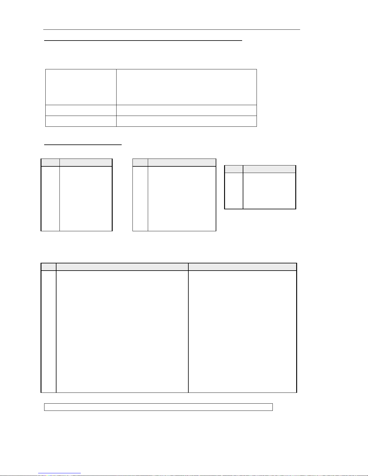
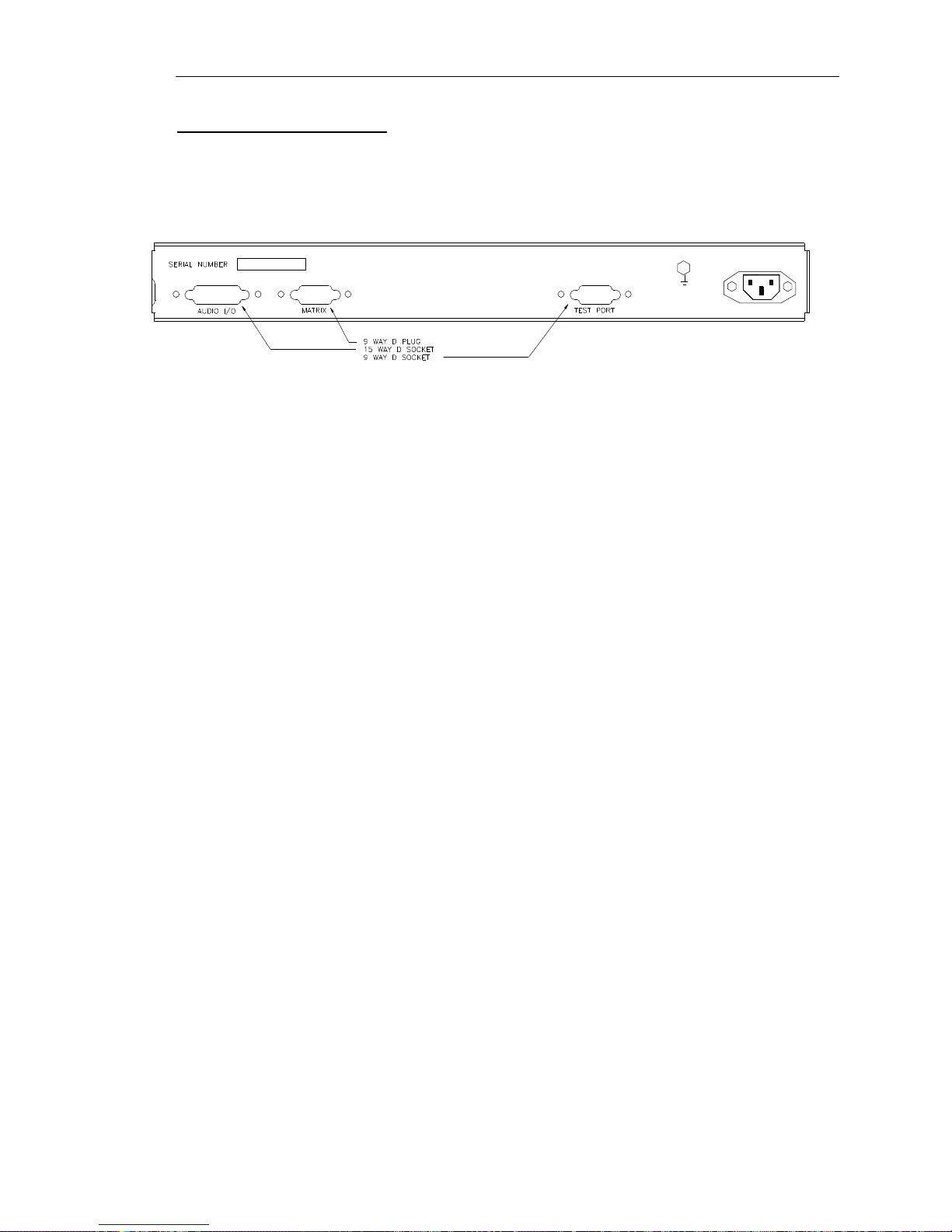
4.2 500-39-30 / 31 1U 12 key Standalone Panel with loudspeaker
This panel provides more basic facilities than the 500-30 range. It does not have LCD
displays and only provides connection to the matrix, audio I/O and the test port at the rear.
An installation specification is given below.
Dimensions 485mm wide x 44.5mm high x 150mm deep
(excluding connectors) 200m approx. (including
mating connectors)
19” x 1RU rack mounting
Mains Input 90 – 260 V ac, 50-60Hz
Current Consumption 150 – 50mA
4.2.1 Connector Pin Out
Matrix – 9D Fixed Plug
Pin Function
1 NC (Screen)
2 Data Out3 Data In4 Audio Out5 Audio In6 Data Out+
7 Data In+
8 Audio Out+
9 Audio In+
Test– 9D Fixed Socket
Pin Function
1 Analyse Input
2 Enable Remote Boot
3 Ground
4 Transputer Link Out+
5 Transputer Link In+
6 Error signal Out
7 Reset In
8 Transputer Link Out9 Transputer Link In-
Headset - 5 Pin XLR Fixed
Socket (front panel)
Pin Function
1 Mic IN (Screen)
2 Mic IN
3 Headset Gnd
4 Headset Out
5 Headset Out
Audio I/O – 15D Fixed Socket
Pin Function Notes
1 Slave Mic Input Line level, un-balanced
2 +15V Out (for slave mic panel) NOT protected!
3 Clean Mic Out + Line level, balanced, pair with 11
4 Ext CUT Input (for slave mic panel) Parallel function to front panel Cut
Switch. Ground to activate
5 Chassis Ground
6 No connection
7 External Input to LS Amp - Line level, balanced, pair with 14
8 Matrix Audio Input to Panel / parallel output - Line level, balanced, pair with 15
9 Ext Mic Cut output (to slave panel) Normally grounded. O/P is open
circuit when front panel cut selected.
10 -15V Out (for Slave mic panel) NOT protected
11 Clean Mic Out - Line level, balanced, pair with 3
12 Mic Ground
13 Loudspeaker Output 8 ohm loudspeaker
14 External Input to LS Amp + Line level, balanced, pair with 7
15 Matrix Audio Input to Panel / parallel output + Line level, balanced, pair with 8
NB 15V supplies are also used to derive 12V for panel. (Thermally Fused @ 0.7A)
The 500-39-31 panel includes additional expansion in and out connectors in the same format
as the 500-40 series expansion panels. It is only available to special order. See section 4.4.1
for connector details.
Page 23
Orator Installation Guide
Issue 2Trilogy Broadcast Limited Page 23 of 37
Orator
4.2.2 500-39-30 Rear View
Page 24
Orator Installation Guide
Page 24 of 37 Issue 2 Trilogy Broadcast Limited
Orator
4.3 500-41 Series Desktop Panels
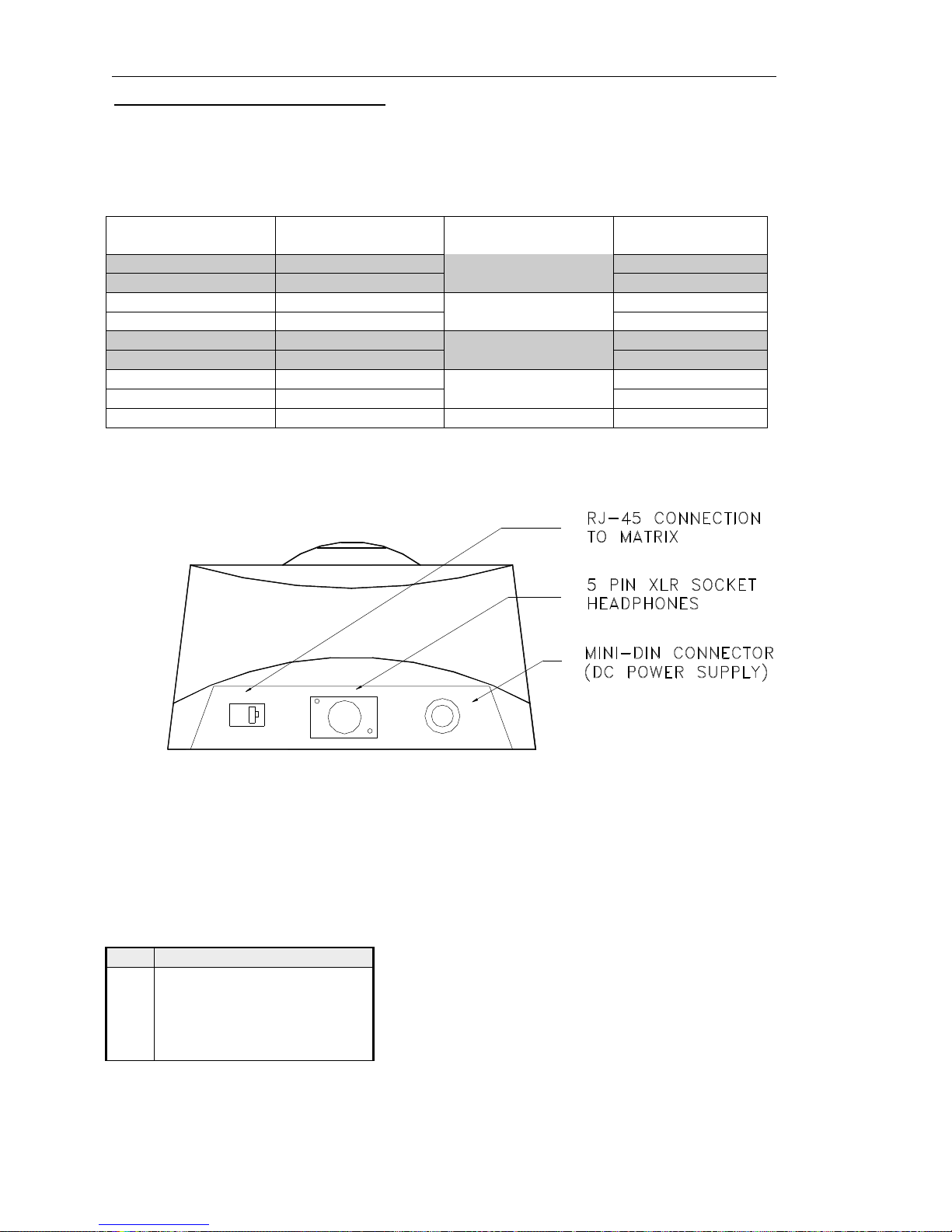
These differ from the other control panels since the matrix link is via a RJ-45 connector. The
pin-out is given in the table below. To make a cable, use a 9-way plug at the matrix end. The
following wiring applies to panels marked "Mod State 2" and later. Earlier panels had pins 4
and 6 transposed internally, with corresponding changes to the interconnecting cable. The
later wiring allows operation over longer lengths of structured cabling.
RJ-45
Pin
Function 9 way D Free Plug
at matrix end
1 Panel Data out + 6
2 Panel Data out -
Pair 1
2
3 Panel Data In + 7
6 Panel Data In -
Pair 2
3
5 Panel Audio out + 8
4 Panel Audio out -
Pair 3
4
7 Panel Audio in + 9
8 Panel Audio in -
Pair 4
5
Cable Screen 1
The next diagram shows a rear view of the desktop panel.
For connection via structured cabling, RJ45 to 9 way D adaptors are available from
electronic distributors. See section 4.5 for further details.
The desktop panel is DC powered from a mains power supply unit connected via the mini
DIN connector on the rear. The only remaining user connection is to the Headset connector
on the rear of the desktop. The pin-out is:
Headset - 5 Pin XLR Fixed Socket
(rear panel)
Pin Function
1 Mic IN (Screen)
2 Mic IN
3 Headset Gnd
4 Headset Out
5 Headset Out
Page 25

Orator Installation Guide
Issue 2Trilogy Broadcast Limited Page 25 of 37
Orator
4.4 500-40 Series Expansion Panels
Control Panels may be linked together to provide additional facilities at one operating
position. Additional level controls (RENs) or switches may be added. Alternatively, two
standard panels from the 500-30 series may be linked together and will only utilise a single
matrix port.
The following detail refers to these panel types:
Ø 500-40-00 8 way encoder panel
Ø 500-40-01 12 way encoder panel
Ø 500-40-02 15 key expansion panel
An installation specification is given below.
Dimensions 485mm wide x 44.5mm high x 100mm deep
(excluding connectors) 150mm deep (max,
including mating connectors)
19” x 1RU rack mounting
Mains Input 90 – 260 V ac, 50-60Hz
Current Consumption 150 – 50mA
4.4.1 Connector Pin Out
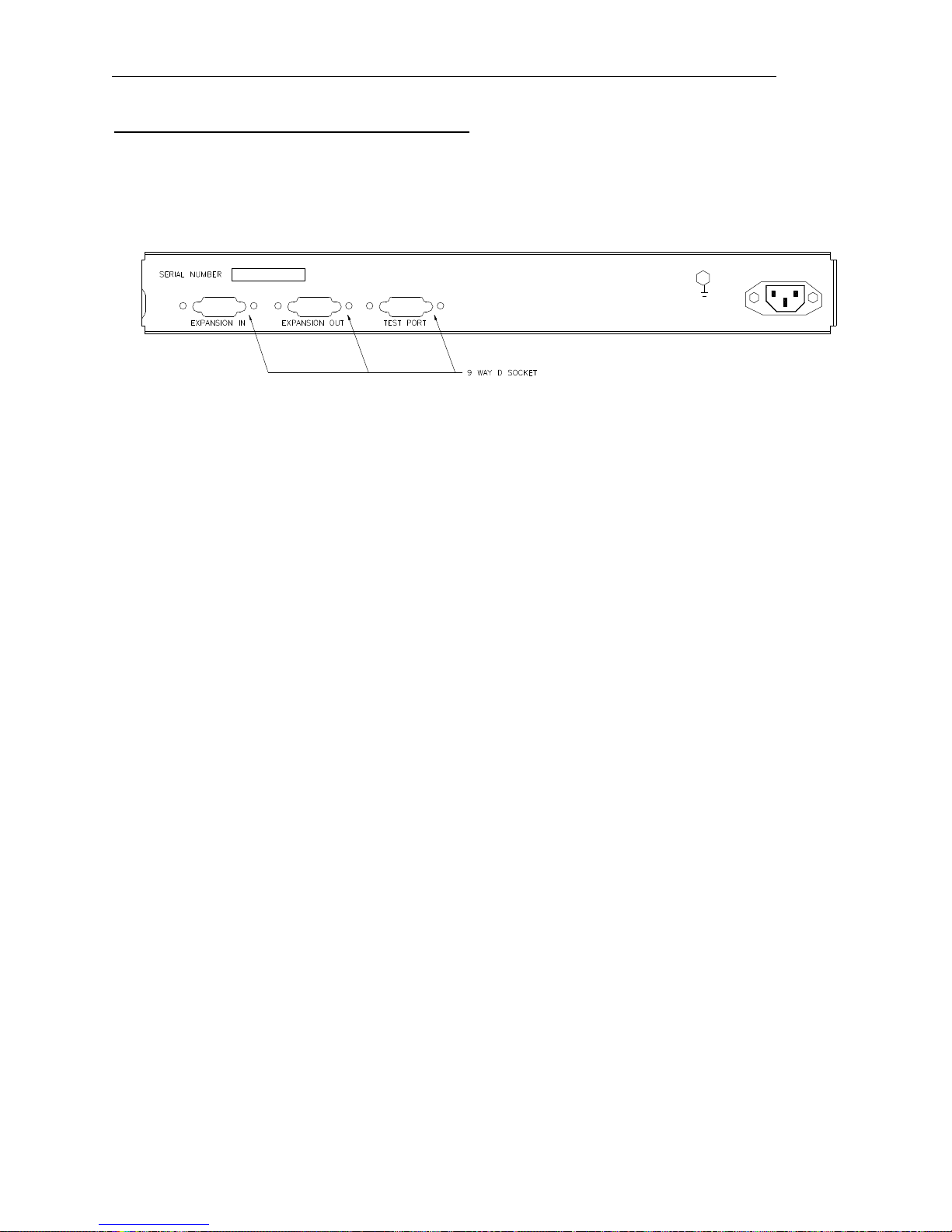
Test Port– 9D-Fixed Socket
Pin Function
1 Analyse Input
2 Enable Remote Boot
3 Ground
4 Transputer Link Out +
5 Transputer Link In +
6 Error signal Out
7 Reset In
8 Transputer Link Out9 Transputer Link In-
Expansion Port In– 9D-Fixed Socket
Pin Function
1 Analyse Input
2 Enable Remote Boot
3 Ground
4 Transputer Link Out +
5 Transputer Link In +
6 Error signal in
7 Reset Out
8 Transputer Link Out9 Transputer Link In-
Expansion Port Out– 9D-Fixed Socket
Pin Function
1 Analyse Input
2 Enable Remote Boot
3 Ground
4 Transputer Link In +
5 Transputer Link Out +
6 Error signal out
7 Reset In
8 Transputer Link In9 Transputer Link Out-
Page 26
Orator Installation Guide
Page 26 of 37 Issue 2 Trilogy Broadcast Limited
Orator
4.4.2 500-40 Series Control Panel Rear View
Page 27

Orator Installation Guide
Issue 2Trilogy Broadcast Limited Page 27 of 37
Orator
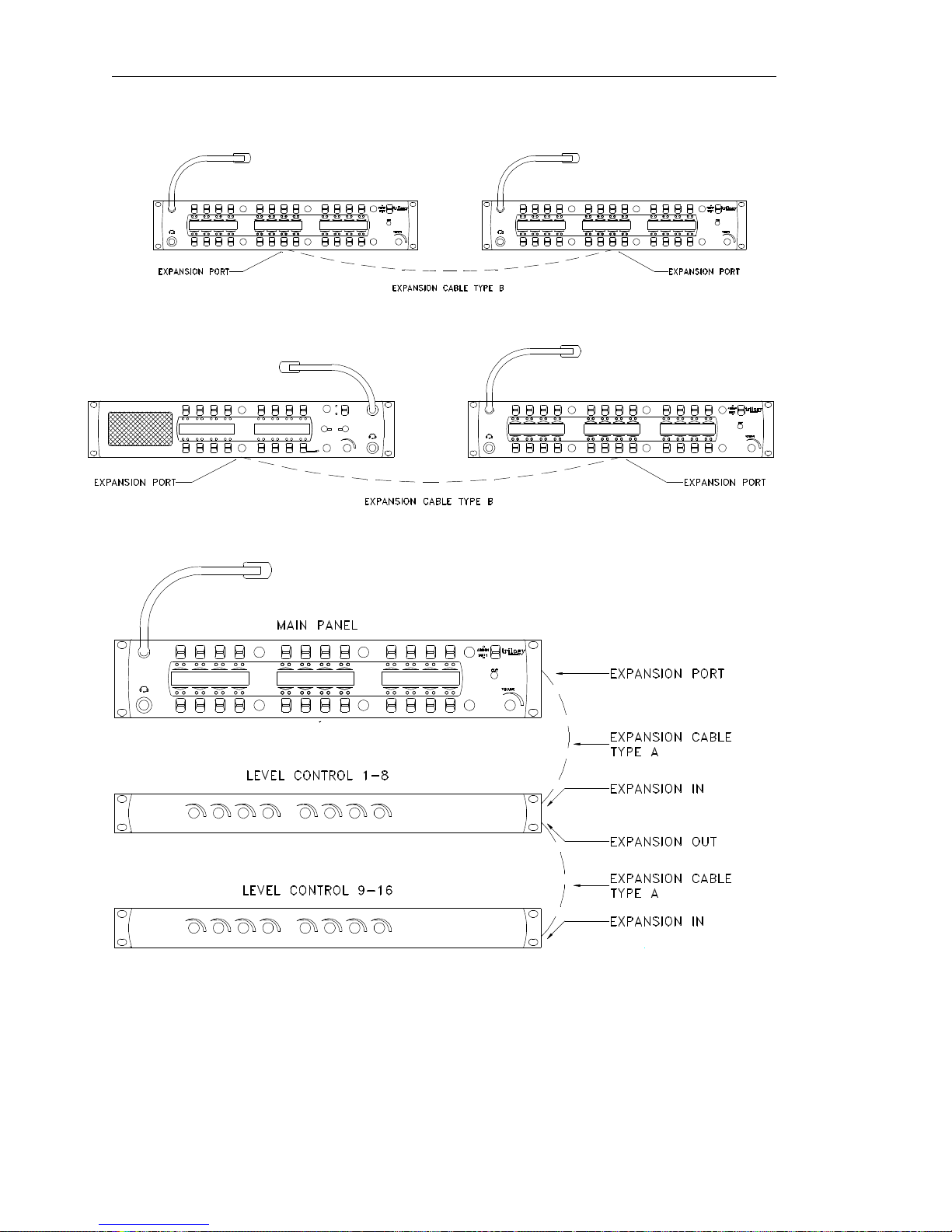
4.4.3 Typical expansion panel configuration
Since the 500-30 series panels (“Standard” 8 / 16 / 24 key) only have a single expansion
connection, they must form either the first or last panel in a chain. Expansion panels from the
500-40 range have both Expansion In and Expansion Out connectors, allowing them to be
connected in a chain. The PathFinder Lite configuration software includes full expansion
panel support (from version 4.12 onwards). This controls the sequence in which the panels
should be added to the configuration editor and the electrical interconnection sequence.
Obviously, the panels may be assembled into the control desk in any preferred positions,
cable lengths permitting. Two different cable types are required, Type A and Type B which
are detailed in section 4.4.4.
The following rules need to be observed when connecting expansion panels onto a system:
Ø The standard series panels have only a single expansion port, used as “EXPANSION IN”
or “EXPANSION OUT”. Therefore, these panels must be connected on the beginning or
end of a chain only.
Ø Standard control panels (500-3x series) used in expansion mode need the internal DIP
switch 1 set to “ON”. If the panels are supplied as part of a pre-configured system, this
will be carried out by Trilogy and the panels marked accordingly.
Ø When a standard panel appears at the end of a chain, it must be connected using cable
type B (see 4.4.4).
Ø The audio only operates on the first panel of the chain: if required, the microphone may
be removed from the second “standard” panel. Trilogy can supply a blank plug for the
mic fixing.
Ø The maximum suggested cable length for interlinking cables is 10 metres.
A number of different arrangements are shown below; others are possible.
Page 28
Orator Installation Guide
Page 28 of 37 Issue 2 Trilogy Broadcast Limited
Orator
Page 29

Orator Installation Guide
Issue 2Trilogy Broadcast Limited Page 29 of 37
Orator
4.4.4 Expansion panel interconnection cables
Type A (max length 10 metres)
9 way D Free
Plug - Pin
Function Function 9 way D Free
Plug - Pin
4 Transputer
Data out +
Transputer
Data in +
4
8 Transputer
Data out -
Pair 1
Transputer
Data in -
8
5 Transputer
Data In +
Transputer
Data out +
5
9 Transputer
Data In -
Pair 2
Transputer
Data out -
9
3 Ground Ground 3
Type B (max length 10 metres)
9 way D Free
Plug - Pin
Function Function 9 way D Free
Plug - Pin
4 Transputer
Data out +
Transputer
Data in +
5
8 Transputer
Data out -
Pair 1
Transputer
Data in -
9
5 Transputer
Data In +
Transputer
Data out +
4
9 Transputer
Data In -
Pair 2
Transputer
Data out -
8
3 Ground Ground 3
4.5 Connecting via structured cabling
All control panel types may be connected to the matrix by Category 5 structured cabling
systems. Suitable adaptors are available from most electronic component distributors. The
RS part numbers are listed below.
Panel Connection: RJ45 to 9 way D socket. RS 818-700
Matrix Connection: RJ45 to 9 way D plug. RS 818-693
As supplied, these adaptors require the pins to be inserted into the D type housing. Use the
following table as a guide. The colour codes may not be correct for other manufacturers.
D type pin RJ 45 pin Colour (see above)
1 No connection No connection
2 2 Yellow
3 6 Brown
4 4 Red
5 8 Blue
6 1 Black
7 3 Orange
8 5 Green
9 7 Grey
Page 30

Orator Installation Guide
Page 30 of 37 Issue 2 Trilogy Broadcast Limited
Orator
Page 31

Orator Installation Guide
Issue 2Trilogy Broadcast Limited Page 31 of 37
Orator
5. OTHER EQUIPMENT
5.1 Belt Boxes
Belt Boxes may be connected to the Orator matrix, on ports configured as 4 wire. They
require an external voltage supply, either +15V or µ 15V depending on the type number. If
the belt-boxes have been supplied as part of the initial system, then an external voltage
connector will have been fitted to the Orator power supply. The tables below show the
different types available.
Type No. of
input
channels
#
Fixed Connector
type
Mating Connector
type required
Voltage
required
410-50-02 1 XLR6 Male XLR6 Female +15V
410-50-03 2 Hirose 12 Way Plug
RM15TRD-12P
Hirose 12 Way Socket
RM15TPD-12S
± 15V
410-50-04 3 Hirose 12 Way Plug
RM15TRD-12P
Hirose 12 Way Socket
RM15TPD-12S
± 15V
# All Belt Boxes have one output channel.
The following tables give individual connector pin-outs for each type.
410-50-02 Single Channel Belt Box
Connector Pins Function
1,2 (+,-) Audio from box
3,4 (+,-) Audio to box
5 0V
6 +15V
410-50-03 Two Channel Belt Box
Connector Pins Function
1 Chassis
2,3 (+,-) Audio 1 to box (PTB)
4,5 (+,-) Audio 2 to box (Prog Snd)
6,7 (+,-) Audio from box
8 +15V
9 -15V
10 OV to box
11,12 (+,-) N/c
410-50-04 Three Channel Belt Box
Connector Pins Function
1 Chassis
2,3 (+,-) Audio 1 to box (PTB)
4,5 (+,-) Audio 2 to box (Prog Snd)
6,7 (+,-) Audio from box
8 +15V
9 -15V
10 0V to box
11,12 (+,-) Third audio to box
Page 32

Orator Installation Guide
Page 32 of 37 Issue 2 Trilogy Broadcast Limited
Orator
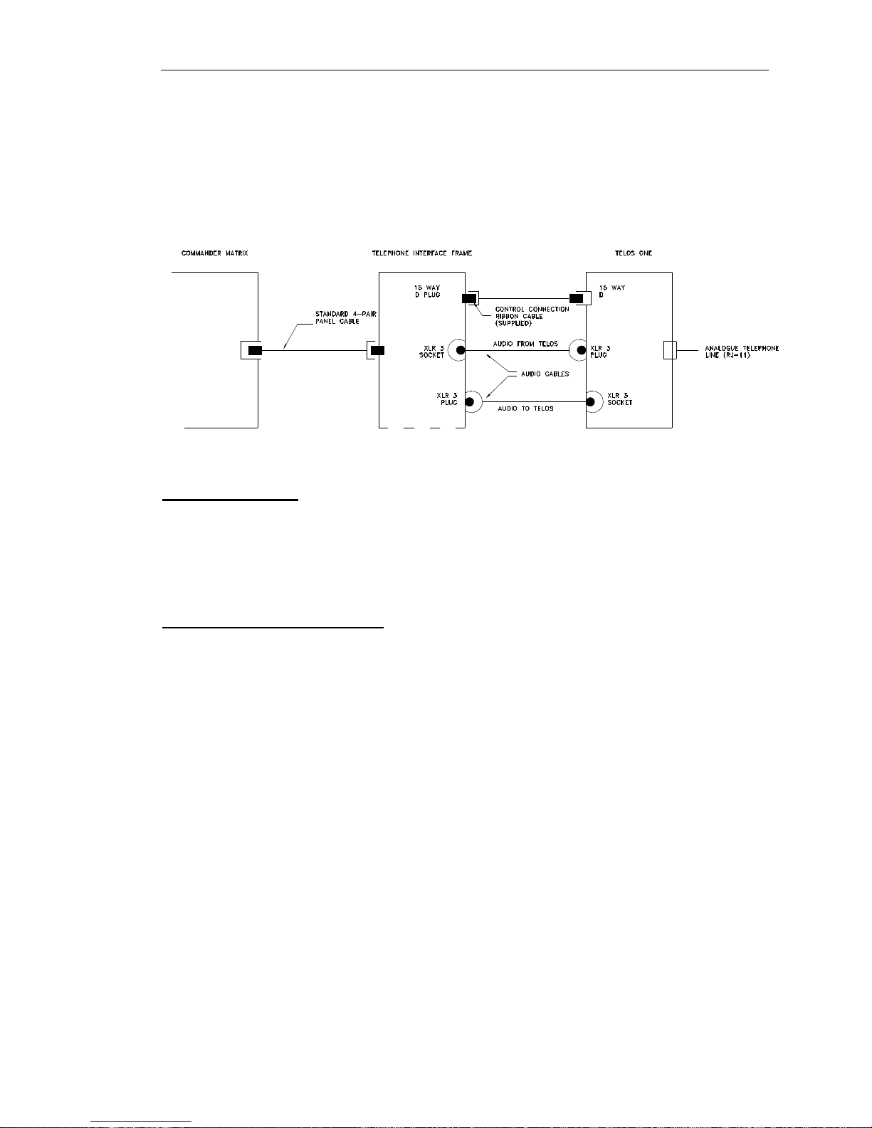
5.2 Telephone Interfaces
The Trilogy 500-19 range of equipment provides full DTMF telephone facilities when used in
conjunction with the Telos ONE “smart” telephone hybrid. To obtain the full facilities
available with the Orator system, the Telos ONE should be fitted with the Telos Super Auto
Answer (SAA) option. During the installation it is important to remember that the Telephone
Interface must be connected to the matrix via a panel port wired with 4 pair cable. The
connection is not just audio / 4-wire, there is a data exchange between the matrix and
telephone interface. Each 500-19-10 Rack Mounting Frame can contain a maximum of three
500-19-00 Telephone Interface Cards. An installation specification for the frame is given
below.
Trilogy 500-19-10 Telephone Interface Frame
Dimensions 485mm wide x 44.5mm high x 440mm deep
(excluding connectors)
19” x 1RU rack mounting
Mains Input 90 – 250 V ac, 50-60Hz
Power Consumption 45VA
Connector Detail (per channel)
Active link to matrix 9 way D Fixed Plug
Audio to Telos Hybrid 3 pin XLR Fixed Plug
Audio from Telos Hybrid 3 pin XLR Fixed Socket
Control link to Telos Hybrid 15 way D Fixed Plug
Each connection to a telephone line requires a separate Telos ONE hybrid. An installation
specification is given below.
Telos ONE Telephone Hybrid
Dimensions 485mm wide x 44.5mm high x 240mm deep
(excluding connectors)
19” x 1RU rack mounting
Mains Input 100 – 240 V ac, 50-60Hz
Power Consumption 90mA – 50mA
Connector Detail
Audio to Trilogy Telephone Interface 3 pin XLR Fixed Plug
Audio from Trilogy Telephone Interface 3 pin XLR Fixed Socket
Control link to Trilogy Telephone Interface 15 way D Fixed Socket
Telephone Line RJ-11
Page 33
Orator Installation Guide
Issue 2Trilogy Broadcast Limited Page 33 of 37
Orator
If the Telos equipment is purchased separately (i.e. not via Trilogy) it is important to specify
to your supplier that the equipment is for connection to a Trilogy Orator system. This allows
the correct software versions and hardware modifications to be fitted.
A typical system interconnection diagram is given below.
5.3 RT Equipment
Radio Talkback equipment may be supplied by Trilogy as part of a complete system. It is not
manufactured by Trilogy and will be supplied with the original equipment manuals.
The usual configuration consists of one or more Base Stations and a number of portable
transceivers. The Base Stations are connected to the matrix using normal 4 wire audio ports
according to the pin-out information in Section 2.
5.4 ISDN Interface (500-22-00)
The Trilogy ISDN interface is connected in the same manner as the Telos Hybrid (see
Section 5.2). The 1U package contains two 64k-bandwidth channels, which may be used
independently or as a single ISDN2 (128k) bandwidth channel.
To make correct use of the available bandwidth, two separate telephone interface cards
(500-19-10) should be allocated, along with two matrix ports. It is possible to request two
independent incoming telephone numbers, either via your in-house switchboard of (if
appropriate) from your Telecommunications Supplier. In this way, incoming calls can be
directed to either Bearer 1 or 2 and outgoing calls will be connected to the first available
Bearer. Careful programming within the telephone groups area of PathFinder Lite is required
to obtain the best results.
Page 34

Orator Installation Guide
Page 34 of 37 Issue 2 Trilogy Broadcast Limited
Orator
5.4.1 ISDN Interface Connector Pin-Outs
5.4.1.1 Bearer 1 & Bearer 2
Audio Input XLR pin 1 Ground
XLR pin 2 Balanced input 1
XLR pin 3 Balanced input 2
Audio output XLR pin 1 Ground
XLR pin 2 Balanced output 1
XLR pin 3 Balanced output 2
15 pin D-type Pin 1 AUTO control input
Pin 2 DROP control input
Pin 3 +5VDC
Pin 4 D8 DTMF output
Pin 5 D4 DTMF output
Pin 6 D2 DTMF output
Pin 7 D1 DTMF output
Pin 8 Not connected
Pin 9 SIEZE control input
Pin 10 Ground
Pin 11 Line Mode output
Pin 12 Automode output
Pin 13 DTMF data valid
Pin 14 Not connected
Pin 15 Not connected
5.4.1.2 ISDN Interface RJ45 Connector
Pin1 Not connected
Pin 2 Not connected
Pin 3 Tx to network A/Rx from terminal A
Pin 4 Rx from network A/Tx to terminal A
Pin 5 Rx from network B/Tx terminal B
Pin 6 Tx to network b/Rx from terminal B
Pin 7 Not connected
Pin 8 Not connected
5.4.2 Notes
5.4.2.1 Com Port
This feature will be supported in future software releases.
5.4.2.2 Remote Ports
Each input is the cathode of the LED on an opto-isolator. The anode is connected through a
470R resistor to +5VDC. Therefore to activate a control input, short the pin to ground, i.e. pin
10. Each output is the open collector of a ULN2003 driver chip. Therefore connect the pin
through load to +5VDC.
5.4.2.3 RJ45
This is the ISDN 2 connector. This must only be connected to an approved ISDN 2
connection or serious damage may occur.
Page 35

Orator Installation Guide
Issue 2Trilogy Broadcast Limited Page 35 of 37
Orator
6. SPECIFICATION
6.1 General
Number of Ports 18 or 36 if second audio card is fitted.
6.2 Matrix Audio Specification
Port Type 4 wire electronically balanced
Frequency Response -3dB @ 25Hz and 15.5kHz
Nominal Gain 0dB ± 1dB
Gain Adjustment Range +12dB / -37dB from PathFinder Lite
Maximum Input Level +20dBu
Crosstalk < -60dB worst case
Noise < -55dBu CCIR weighted, quasi-peak
Distortion < 0.2% THD @ 0dB gain
Input Impedance ~10kR
Output Impedance Low (<20R)
6.3 Real Time Performance
Transmission time delay <50ms (defined as time taken from a key press to the audio
reaching the destination). Based on statistical analysis of the likely number of key presses at
any given instant.
6.4 Panels
Panel Communication Balanced RS422 at 230.4 kbaud
Power See individual sections
Maximum cable run >600m.
Connection to Matrix 4 twisted pair cable. STP recommended:
UTP acceptable.
L/S Volume Control Max attenuation or hold off adjustable from -
20 to -76dB in PathFinder Lite
Microphone amplifier gain adjustment +14 to -16dB from PathFinder Lite
Loudspeaker amplifier Nominal 5W into 8R
Page 36

Orator Installation Guide
Page 36 of 37 Issue 2 Trilogy Broadcast Limited
Orator
6.5 GPIO Specification
Number of physical Inputs 8, grounding contact
Number of physical Outputs 8, earth-free opto-isolated mosfet
Loopback I/O Outputs 9 to 16 internally loped back to
inputs 9 to 16.
6.6 P.C.
Type Any IBM PC or compatible computer running
Windows 95 / 98. We suggest a Pentium 133
(or better) with a minimum 32Mbyte of RAM.
Support for Windows NT will be added later.
Connection to Matrix Using 8-bit slot adaptor card, RS422 data at
20Mbit/s. The download card uses a default
base address 150(Hex). This can be
changed in case of conflicts. Maximum
common mode/differential voltage on RS422
transceivers ±7V
Maximum Cable Length 10m guaranteed, 40m in practice using
overall screened 100Ω dual twisted pair
cable
Page 37

Orator Installation Guide
Issue 2Trilogy Broadcast Limited Page 37 of 37
Orator
6.7 Internal Panel Switch Settings
Id DIP Switch Action DIP1DIP2DIP3DIP4DIP5DIP6DIP
7
Legacy
Emul.
DIP
8
5/8
Char
0 8 Key or Desktop OFF OFF OFF OFF OFF OFF OFF OFF
1 8 Key Expansion ON OFF OFF OFF OFF OFF OFF OFF
2 16 Key OFF ON OFF OFF OFF OFF OFF OFF
3 16 Key Expansion ON ON OFF OFF OFF OFF OFF OFF
4 24 Key OFF OFF ON OFF OFF OFF OFF OFF
5 24 Key Expansion ON OFF ON OFF OFF OFF OFF OFF
8 8 REN Expansion OFF OFF OFF ON OFF OFF OFF OFF
9 12 REN Expansion ON OFF OFF ON OFF OFF OFF OFF
10 32 Channel Level Control OFF ON OFF ON OFF OFF OFF OFF
11 12 Key 1U ON ON OFF ON OFF OFF OFF OFF
12 15 Key 1U Expansion OFF OFF ON ON OFF OFF OFF OFF
6.8 500-41 Desktop Panel Internal Settings
A three way connector inside the panel may be fitted with links in any of the three positions
labelled H, L or M. These provide the same functionality as the switches accessible from the
top edge of the 500-30 series control panel.
Cut Switch Action H L M
No action
X X X
Changeover to HSet MIC
v
X X
LS cut
X
v
X
Changeover to HSet MIC and LS cut
v v
X
MIC cut
X X
v
Changeover to HSet MIC and MIC cut
v
X
v
LS cut and MIC cut
X
v v
Everything
v v v
v indicates link fitted
X indicates link not fitted
In addition, the 500-41 desktop panel is factory configured to operate with PathFinder Lite
systems. To set the panel software to emulate T-Edit systems, solder a shorting link in the
position labelled R130. This requires surface mount soldering tools: contact Trilogy for
further advice.
 Loading...