

Page 1
Step 1.
PLANNING FOR THE INSTALLATION
TOOLS REQUIRED
In planning for the installation of a new Trilogy Pool, there are
many important considerations that must be evaluated in order to
achieve a functional, long-lasting and aesthetic addition to a home.
When choosing a location, consider the following:
1. Grade: Pools and decks are normally constructed on level ground.
Extreme variations in grade should be resolved before the excavation of
the pool begins. A relatively level and at location is preferred so time
and effort is not wasted on radical uctuations in grade.
2. Excavation Equipment Access and Pool Delivery: Determine the
most efcient route for equipment to enter and access the site. Also keep in mind that a well planned route can save
time and money by enabling multiple pieces of equipment to work in unison. For example: Coordinate the delivery of the
pool with the completion of the excavation and prepping of the hole. If a track excavator was used to prepare the site, it
may also be utilized to unload and set the pool. Finally, consider the placement of the equipment. If possible, position
the equipment so the pool can be unloaded and placed directly into the excavation.
3. Underground Utilities: Check with local authorities for the locations of underground water, gas, power and sewer lines.
4. Overhead Power Lines.
5. Local Building Codes: Determine the setbacks from property lines, easements, house footings, etc.
A. Transit Level
B. Shovel
C. Pick
D. Rake
E. Stakes and nails
F. Spray paint for outlining pool
G. String
H. Hammer
I. (7) 2”x 4” x 16’
J. Tape Measures: 25’ and 50’ lengths
6. Water Drainage: Water should always drain away from the pool. Failure to keep ground water away from the exterior
of the pool may result in damage to the pool that is not covered under warranty.
7. Local Fencing Codes.
8. Location of Pool Equipment: Locate to within 20’ of pool.
9. Electrical Run for Pool Equipment.
10. Underground Water Conditions.
11. Exposure to Sunlight.
12. Surrounding Foliage.
13. View from Residence.
Notice: Failure to read and follow specic instructions contained in this manual will void your pool warranty.
Nebula
Page 2
Step 2.
FIG. 1
POOL LAYOUT
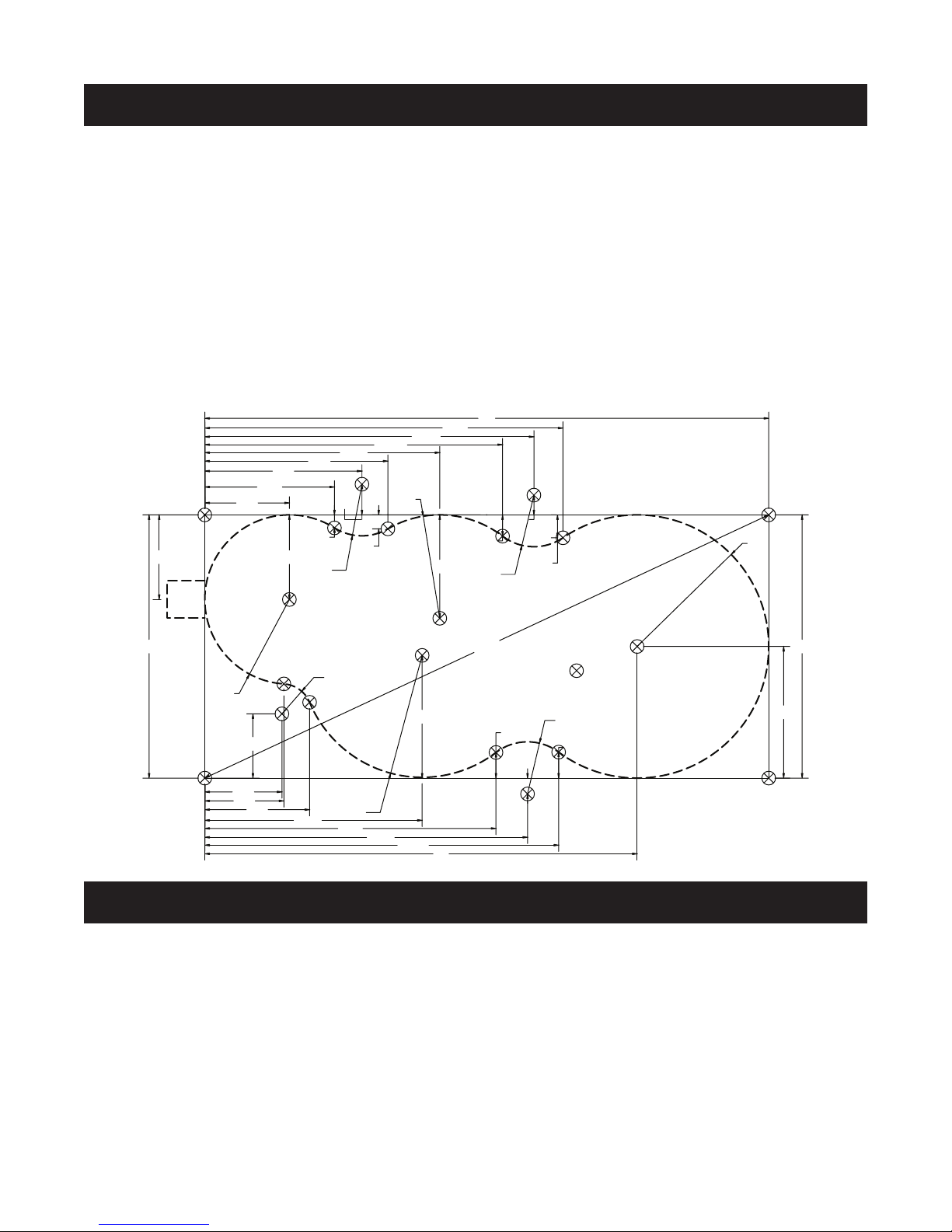
When laying out the pool, note that the dimensions are to the outside edge of the pool coping. Most permit
plans are measured to the waters edge. The coping of a Trilogy Pool is approximately 6” on all sides. There is a difference of 12” between the length and width dimensions in the installation guide and those of the permit plans. Depending on the customer and the local building inspector, this fact can be a critical consideration. Distances between the
water’s edge to most property lines, electrical lines, and other structures such as houses, garages, sheds and patios
must be exact to plan specications.
Start with a 14’ wide by 30’ long rectangle with diagonal measurements of 33’ 1” (the diagonal measurements
insure that your layout is square). Place stakes in the ground at each corner of the rectangle, then place the remaining
stakes in the ground as shown in Figure 1. Connect the stakes with string. Use spray paint to follow the contour of the
string. Remove the string and stakes, leaving only the outline of the pool.
30'
19'-1"
17'-6"
15'-10"
12'-6"
9'-9"
8'-4"
4'-6"
2'x2'
3' DP
4'-6"
6'-11"
1'-8"
8"
4'-6"
R2'-9"
R5'-6"
1'-1"
5'-6"
1'-2"
R2'-9"
1'-3"
9"
R7'
14'
R4'-6"
Step 3.
3'-5"
4'-1"
4'-2"
5'-7"
11'-7"
ELEVATION
R1'-7"
R6'-6"
15'-6"
17'-2"
6'-6"
18'-10"
23'
33'-1"
STAKES -
1'-4 3/8"
10"
R2'-9"
1'-4 9/16"
14'
7'
Elevation and grade of the pool area are two of the most often overlooked or miscalculated variables in the
installation process. While considering all the variables concerning elevation and grade, always remember that you want
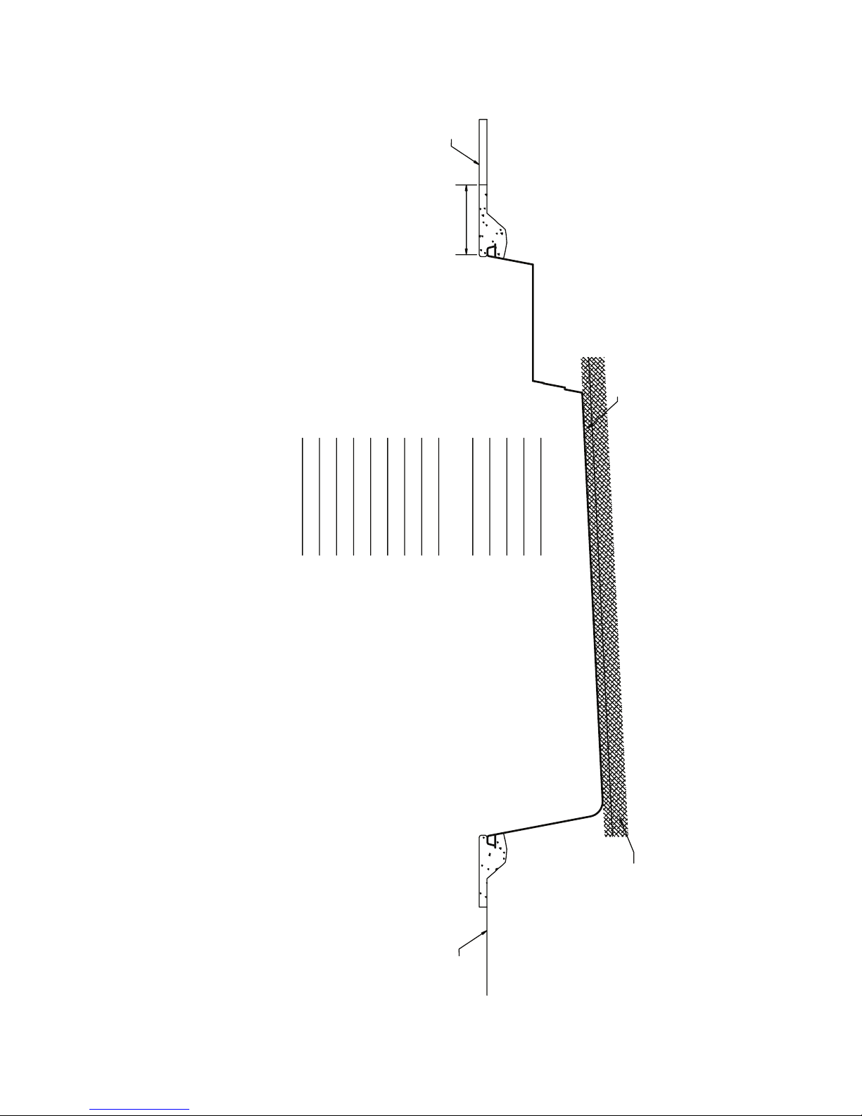
water to run away from the pool. Before excavation, use the provided Installation Planning Guide to calculate all critical
measurements (Form 1).
Check the four corners of the pool layout with the aid of a transit level or a sight level to determine the highest
corner. This corner will be used in planning the elevation of the pool. In a typical installation, the elevation of the pool
should be 4-6 inches above the existing grade around the pool. However, careful consideration should be given to pool
type, size and drainage of the future pool deck, as well as the elevation of the surrounding landscape and existing structures, patios and sidewalks.
Page 3
** FINISH GRADE
FORM 1
DISTANCE TO POOL
EXISTING PATIO
3" - 4" SAND
=
- 3.5"
-
=
+ 49" or 4'-1"
=
=
+ 3.5"
==+ 3.5"
+ 72" or 6'-0"
Job: Pool: Nebula Date:
* SLOPE = DISTANCE TO POOL X .25 (1/4")
** IF POOL IS INDEPENDENT OF ANY EXISTING
STRUCTURES OR PATIOS, FINISH GRADE IS
TO BE 3 1/2" BELOW EDGE OF POOL DECK.
INSTALLATION PLANNING GUIDE
Finish Grade
* Slope
Top of Concrete at Pool
Thickness of Concrete
Top of Pool
Shallow End Depth
Top of Sand Shallow End
Thickness of Sand
Top of Dig Shallow End
Top of Pool
Deep End Depth
Top of Dig Deep End
Thickness of Sand
Top of Sand Deep End
UNDISTURBED SOIL
** FINISH GRADE
Page 4
Step 4.
FIG. 2
EXCAVATION
Correct excavation of the pool is very important. A hole that is too small can mean hours of picking and shoveling by hand. A hole that is too large will require extra import material, which if not dealt with properly, can result in settling or bulging of the pool.
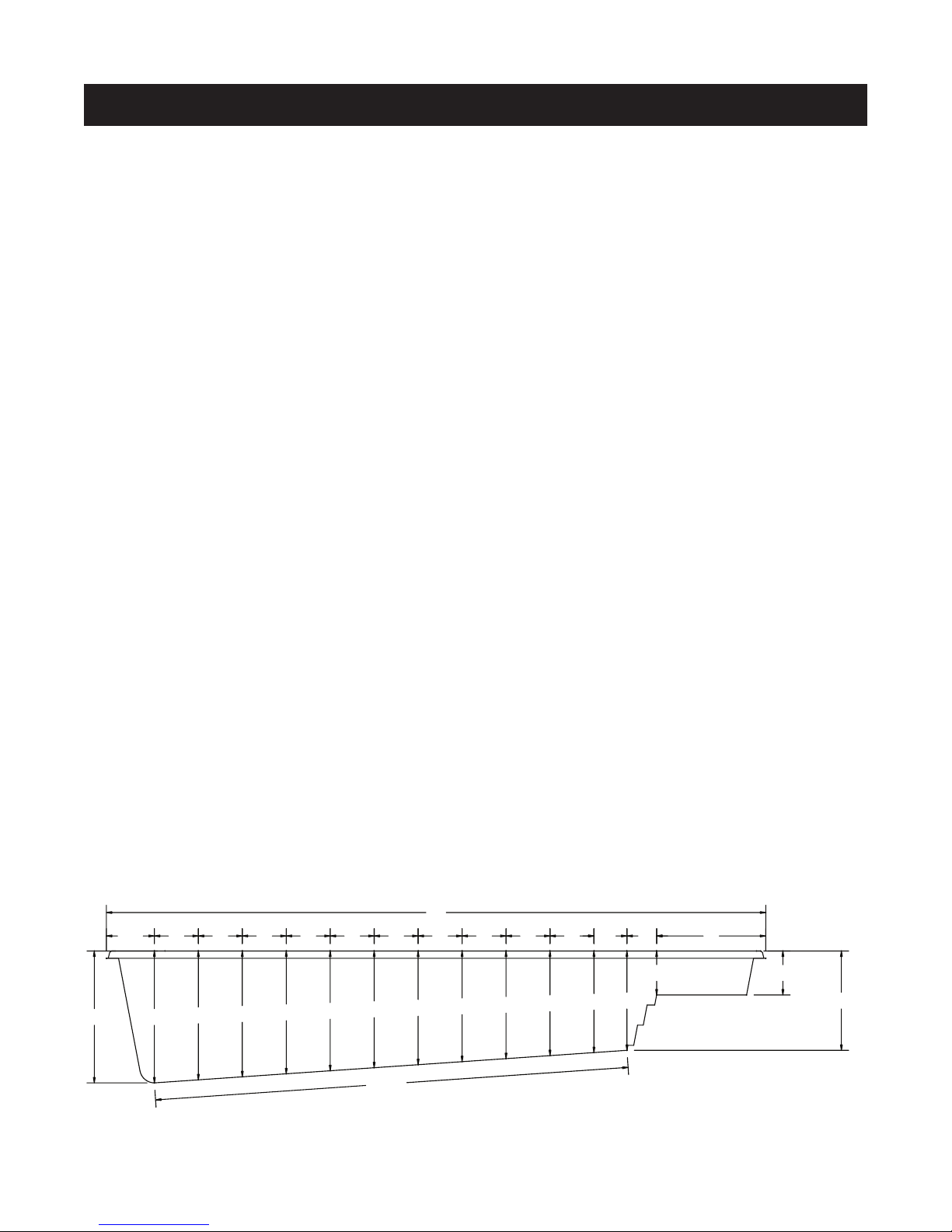
The excavation should be dug very close to the pool size with a minimum disturbance to the unexcavated soil
which will support the pool. The clearance is approximately 6” on the sides and 6” on the ends (Fig 2). The depth of the
excavation is determined with the use of a transit level and a measuring stick. The bottom of the excavation is over dug
approximately 4”. This size pool will require approximately 25 to 30 yards of sand for backll (more may be required if
the pool is over dug).
The excavation should be 14’ by 30’, with a total depth of approximately 4’ 4” (shallow end) to approximately
6’ 3” (deep end) from the desired elevation of the pool. It can be helpful to give yourself extra room the rst 6” in width
and 12” in depth of the hole, to get past the coping, and allow space for the skimmer and the main drain. Also, keep in
mind that the wall of our pools are tapered, usually 1” in for every 12” in depth. A place for the skimmer must also be
dug in the side of the excavation wall. The skimmer cutout should be 2’ by 2’ and 3’ deep. See Figure 1. for placement.
If dramatic over digging occurs in the bottom of the hole, never use excavated material to ll in the hole to the
desired depth. The material will settle. We suggest road base (a tamper may be needed) compacted thoroughly, and
topped with sand. If the sides of the hole are dramatically over dug, road base should be used beyond the six inches
of sand. Both should be compacted thoroughly during the backll process. In the case of over excavation on the sides
of the pool in seasonal high water or poor drainage areas, you may want to mix 10% Portland cement to the backll for
stabilization.
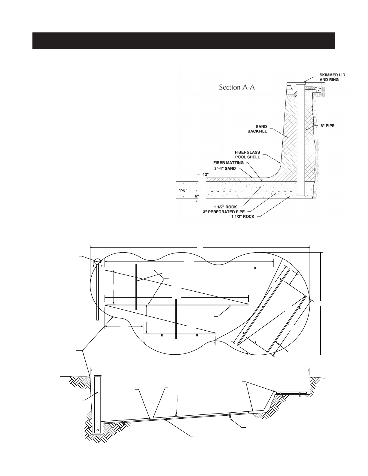
In areas that experience seasonal high water or experience considerable water seepage during excavation, a
permanent sump line (see Cross Section A-A) must be installed to alleviate the excess water and the associated hydrostatic pressure accompanying it. Trilogy suggests digging an 18” x 8’ x 18” trench across the deep end of the excavation. Six inches of 1 1/2” rock should be placed in the bottom of the trench. A joint of 3” perforated PVC pipe is placed
on the rock base and connected to a vertical stand of 8” PVC pipe running to the surface of the excavation. The 8” PVC
should be trimmed with a skimmer ring and lid for aesthetics and safety. After the connection has been to the vertical
stand of 8” PVC, nish covering the 3” perforated PVC pipe with 1 1/2” to 2” rock to the bottom of the excavation (See
Cross Section A). Cover the new sump line with fabric. The bottom of the excavation is now ready for approximately 4” of
sand bedding.
30'
1'-4"
6' 6'
5'-10"
5'-9"
5'-7"
5'-5"
5'-4"
21'-7"
5'-2"
1'-6"
2'2'2'2'2'2'2'2'2'2'2'-2"
2'
4'-6"
4'-7"
4'-11"
5'
4'-9"
5'
2'
4'-6"
Page 5
Step 5.
FIG. 3
PREPARATION OF THE BOTTOM SURFACE OF THE EXCAVATION
The preparation of the excavation bottom is
critical so the pool will t properly. Thorough prepara-
tion will eliminate settling, stress cracks and a minimum of time will be spent setting the pool.
First, install 2” x 4” screed rails length wise
on both sides of the excavation, using wood or metal
stakes (Fig 3). Make sure the diagonal measurement
is exact to insure that the bottom is square. Adjust the
screed rails to the appropriate height using a transit
(see Figure 2). Next, spread a layer of sand approximately 4” deep evenly over the bottom of the excava-
tion. Rake the sand at to the top of the screed rails
(Fig 3). Compaction of the sand is achieved by the use
of water and walking over the entire bottom using your
body for weight. Rake and compact the area several
times. Screed the bottom of the excavation, lling any
low spots as you go. The completed area will resemble
a slab of nished concrete. Remove the screed rails
and ll in the voids with sand, being careful not disturb
the sand.
SEE SECTION A-A
DIG LINE
SUMP SYSTEM
A A
4'-8" 20'-3"
3'-10"
5'-3"
3"-4" OVER DIG
23'-1"
2" x 4" SCREED BOARD
2" x 4" SCREED RAILS
19'-7"
STAKES
15'-8"
9'-11"
NOTE:
POOL SHELL MUST
REST SOLEY ON SAND.
2" x 4" SCREED RAILS
2" x 4" SCREED BOARD
30'
30'
FINISH GRADE
1'-7"
12'-8"
3'-10"
11'-7"
9'-3"
1'-10"
14'
STAKES
STAKES
SAND BED
Page 6
Step 6.
Your pool will arrive on a truck-trailer combination. Be sure to inspect the pool for damage that may have oc-
curred during transportation and for conformity to order specications. A crane or excavator will lower the pool into the
excavation. Please note that Trilogy recommends lifting all pool models over 12’ wide with a spreader bar and 20’ lifting
straps. Once the pool is set in the excavation, the pool should be checked for level and the bottom should be walked
over to detect any voids in the sand that might be present. The pool is then lifted and reset as many times as necessary
to achieve a “good t”. A good t is realized by raking the surface of the sand in order to see where the pool’s perimeter
is touching (footprint) after it is removed and also by walking around on the inside of the pool to detect low spots. It is
normal to feel a slight void under the center of the pool. This will disappear under the weight of the water. It is important
to make certain that the bottom perimeter and all transition points are sitting rmly against the sand bed. The pool can
be separated from the lifting equipment when the entire perimeter of the pool (including all transitions) leaves a clear
footprint and the pool is within 1/2” of level.
A properly prepared hole should not require the lling of large voids beneath the pool. Blindly washing sand
beneath a pool can cause more harm than good. It is important that any adjustments to the pool’s elevation be made
before water is added. If a pool was properly set, nothing more than a few minor adjustments should be needed.
SETTING THE POOL
Step 7.
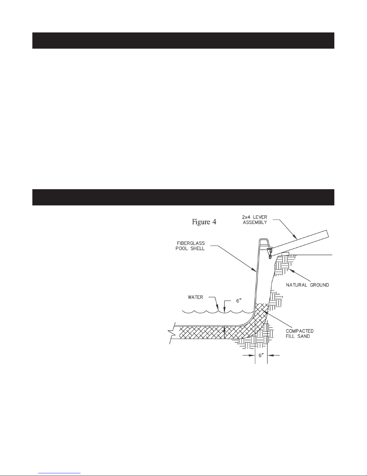
“Locking in” is the process of placing
and tamping the rst 6” of backll around the
radius of the pool to hold it rmly in place during
the installation process. After your pool is “locked
in, start the water in the pool and continue the
backll process. The level of water in the pool
and the level of sand outside the pool should be
within 6” of each other. Continue lling the pool
and backlling until 4” to 6” of water are in the
pool. Check the level of the pool. If the pool was
properly “locked in”, no adjustments should be
necessary. If any movement has occurred, small
adjustments must be made at this time by placing
a lever assembly under the coping of the pool
(Fig 4.). If adjustments are needed, (low condition) raise the pool to the proper height and place
sand under the pool. When the proper height
is achieved, continue the lling and backlling
process. If the pool is to high, remove sand as
needed. It is very important that the radiuses of the pool are packed properly. Poorly packed radiuses can result in
hairline cracks or structural cracks due to deection. Be sure to backll slowly and thoroughly. When the proper height
is achieved, continue with the lling and backlling process.
WATER AND BACKFILL
After approximately 12” of water is in the pool and backll has been placed evenly, the backll should be
allowed to precede the water by 6”. As the water approaches the shallow end, pay particular attention to all the unsupported areas of the pool. Steps and swimouts tend to droop, so slight adjustments may need to be made with the lever-
ing device as mentioned before (Fig 4). Be sure you wait until a sufcient amount of water surrounds the area (usually
12”) to keep the rest of the pool in place, or you may raise more than you intend. The walls of the pool may bulge inward
Page 7
if too much back ll has preceded the water in the pool, or outward if too much water precedes the back ll. If bulging
does occur during the installation, the only remedy is to dig that area out and proceed correctly. Slight bulging has only
visual effects, while not affecting the structure of the pool. A string line is very useful in determining the straightness of
the pool walls during the back lling process.
Step 8.
When the water and back ll levels are close to reaching any of the pool inlets, stop the lling and back lling
process and run the plumbing pipes along the excavation cavity and route them to the equipment site. After the plumb-
ing is installed, complete the lling and back lling process.
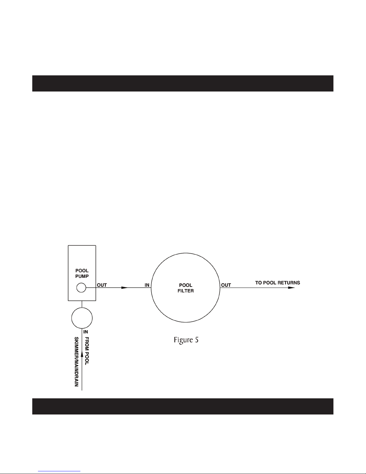
A basic swimming pool circulation system is relatively simple in operation. Water in the pool is drawn through
the main drain and skimmer to the pump, which pushes it through the lter back to the pool via the returns. Refer to
Figure 5 for a basic ltering system diagram. See your contractor for more advanced ltering systems that may include
sanitizers, jets, blowers, automatic pool cleaners, etc. Trilogy recommends the use of schedule 40, 2” plumbing on most
pools. Visually inspect all plumbing installed at the factory upon the delivery of the pool and during the back ll process.
To prevent accidentally draining the pool, Trilogy suggests placing the equipment at or slightly above the elevation of the pool and plumbing the pool so that the water leaves the pool via the skimmer and not the main drain. You
should not place the equipment higher than 6” above pool level. The equipment becomes less ef cient the greater
the distance away from the pool. If the equipment is placed below the water level, shut off valves must be installed to
prevent accidental siphoning of the pool. Pipes may now be glued at the equipment pad and circulation of the ltering
system may begin. Check all connections for leaks and proper circulation before covering them. Local building codes
may require pressure testing of the plumbing system before the installation is complete.
PLUMBING
Step 9.
If the installer or homeowner is not quali ed to do electrical work, an electrician should be hired and a building
of cial should inspect the work. All electrical work should be done to National Electric Code speci cations and any local
codes. Trilogy Pools will not be held responsible for any electrical work.
ELECTRICAL
Page 8
Step 10.
POURING CONCRETE
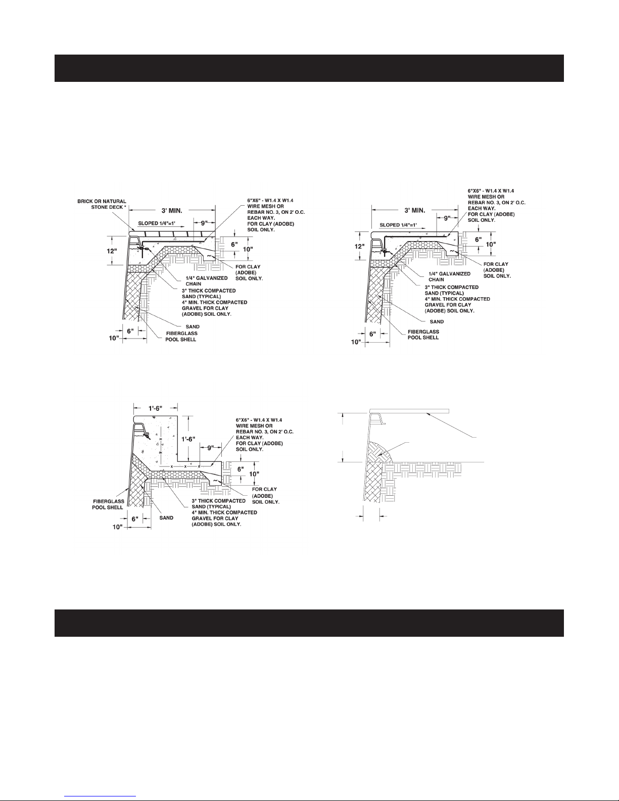
Forms are now put up around the perimeter of the pool. Half inch holes may be drilled into the lip of the pool
every 3’. Two foot lengths of 3/8” rebar are placed in each hole and bent at 90 degree angles (Fig 6-7). This will ensure
a bonding or anchoring effect on the sides of the pool. The walkway may also be reinforced with 6” No. 10 wire mesh or
No. 3 rebar on 2’ centers (Fig 6-7). Trilogy Pools recommends concrete decking. Concrete should be poured at least 3’
around the perimeter of the pool and at least 4” deep. Trilogy Pools will not be held responsible for any concrete work or
cracks that may result from its use.
Figure 6 Concrete Deck with
Brick or Stone
MAXIMUM
19 1/2"
Figure 8 Raised Bench
Installation
Figure 7 Typical Cantilever
Concrete Deck
6"
MOUND DIRT
AROUND POOL
APPROX. 6"
OPTIONAL
WOOD DECK
Figure 9 Typical Above
Ground Installation
WARNING TO THE BUYER
This pool is designed to be kept full at all times. The shell could be damaged if the water level is allowed to drop
below the skimmer. When appreciable draw-down is noticed, or if it becomes necessary to drain the pool, contact Trilogy
Pools, or their agents for instructions. The pool shell may be damaged and separation from the concrete may occur if
the pool is allowed to over ow or if heavy water drainage is allowed to over-run the deck to pool shell connection. Keep
the water level in the middle of the skimmer. Trilogy Pools will not be held responsible for any unforeseen problems or
circumstances which arise from inadequate site drainage or incorrect deck installation. Refer to the Trilogy Pools Warranty sent with the pool for conditions, circumstances, or installation practices that may void the pool’s warranty.
 Loading...