

Page 1

Mercury Core
TRILOGY COMMUNICATIONS LIMITED
User Guide
ISSUE 1.0
2000 Beach Drive
Cambridge Research Park
Cambridge CB25 9TP
United Kingdom
www.trilogycomms.com
Page 2
Mercury Core
The Copyright of the information and drawings in this document is
DOCUMENT NUMBER 70090621.docx ISSUE 1.0
Issue
Date
Reason for Change
Approved
1.0
2 September 2020
Release – v5.2.1.38
the property of Trilogy Communications Limited and is neither to be
reproduced in whole or in part, nor disclosed to a third party,
without the prior written consent of Trilogy Communications
Limited.
The information in this document has been carefully compiled and
checked for accuracy. However, Trilogy Communications Limited
accepts no responsibility for inaccuracies which may occur and,
further, reserves the right to make changes to specification or
design without prior notice.
Comments or correspondence concerning this manual should be
addressed to the Publications Manager at the address given on the
front cover of this document.
Page 2 of 338 Trilogy Communications
Page 3

Mercury Core
Acronyms and Abbreviations
AEB
Audio Expansion Board
AGC
Automatic Gain Control
API
Application Programming Interface
AVB
Analogue Voice Bridge
BDM
Background Debug Module
BIOS
Basic Input/Output System or Basic Integrated Operating System
BMP
Windows Bitmap
COR
Carrier Operated Relay
COTS
Commercial Off-the-Shelf
CTCSS
Continuous Tone-Coded Squelch System
DDI
Direct Dial-In
DEP
Data Execution Prevention
DHCP
Dynamic Host Configuration Protocol
DMA
Direct Memory Access
DNS
Domain Name Server
DSCP
Differentiated Services Code Point
DSP
Digital Signal Processor / Digital Signal Processing
DTMF
Dual-Tone Multi-Frequency
E&M
Ear and Mouth
EC
Echo Cancellation
EDHS
Enterprise Domain Host Subscriber
ENCAP
Encapsulation
ENG
Electronic News Gathering
FIFO
First In -- First Out
FPGA
Field Programmable Gate Array
FXO
Foreign Exchange Office
FXS
Foreign Exchange Station
GPI
General Purpose Input
GPIO
General Purpose Input Output
GPO
General Purpose Output
GUI
Graphical User Interface
HJB
Headset Junction Box
HP
Hyper Terminal
HTTP
Hypertext Transfer Protocol
ICO
Icon file
ID
Identity
IEC
International Electrotechnical Commission
IEEE
Institute of Electrical and Electronics Engineers
IFB
Interruptible FoldBacks
IGMP
Internet Group Management Protocol
IP
Internet Protocol
JRE
Java Runtime Environment
Acronyms and Abbreviations
Page 3 of 338 Trilogy Communications
Page 4

Mercury Core
Acronyms and Abbreviations
LAN
Local Area Network
MAC
Media Access Control
MCF
Mercury Configuration File
MCU
Mercury Communicator Unit
MIDS
Multifunctional Information Distribution System
MIU
Mercury Interface Unit
MMU
Mini Mercury Unit
MTBF
Mean Time Between Failure
NATO
North Atlantic Treaty Organization
NAT/PAT
Network Address Translation /Port Address Translation
NetBIOS
Network Basic Input/Output System
NSA
National Security Agency
OCC
Open Collector
PABX
Private Automatic Branch Exchange
PBX
Private Branch Exchange
PCI
Peripheral Component Interconnect
PHB
Per-Hop Behaviour
POTS
Plain Old Telephone Service
PSTN
Public Switch Telephone Network
PSU
Power Supply Unit
PTT
Push to Talk
QoS
Quality of Service
RAM
Random Access Memory
RH
Relative Humidity
RIB
Radio Interoperability Board
RJ45
Registered Jack 45
RLL
Reliable Link Layer
ROM
Read-Only Memory
RTP
Real-time Transport Protocol
SDK
Software Development Kit
SDRAM
Synchronous Dynamic Random-Access Memory
SIP
Session Initiation Protocol
SNG
Satellite News Gathering
SRAM
Static Random-Access Memory
SVGA
Super Video Graphics Array
TBC
Talkback Controller
TCP
Transmission Control Protocol
TCP/IP
Transmission Control Protocol / Internet Protocol
TEB
Telephone Expansion Board
TFTP
Trivial File Transfer Protocol
TTL
Transistor-Transistor Logic
UAC
User Access Control
UDP
User Datagram Protocol
Page 4 of 338 Trilogy Communications
Page 5

Mercury Core
Acronyms and Abbreviations
UPS
Uninterruptible Power Supply
USB
Universal Serial Bus
VAD
Voice Activity Detector/Detection
VID
VLAN ID
VIF
Voice Information Field
VLAN
Virtual Local Area Network
VoIP
Voice over Internet Protocol
VOX
Voice Operated Transmission
VPAN
Virtual Panel
VPN
Virtual Private Network
WAN
Wide Area Network
WMF
Windows Metafile
Page 5 of 338 Trilogy Communications
Page 6

Mercury Core
CONTENTS
1. INTRODUCTION ....................................................................................................... 12
1.1 O
1.2 R
1.3 T
1.4 W
2. SYSTEM INSTALLATION ............................................................................................ 14
2.1 U
2.2 E
2.3 M
2.4 N
2.5 T
2.6 N
3. MERCURY NETWORK HOSTS .................................................................................... 17
3.1 O
3.2 C
4. MERCURY INTERFACE UNIT (MIU) ............................................................................ 18
4.1 O
4.2 MIU
4.3 E
4.4 I
4.5 R
4.6 C
4.7 I
4.8 R
VERVIEW .............................................................................................................................. 12
ELATED DOCUMENTS .............................................................................................................. 12
ECHNICAL SUPPORT ................................................................................................................ 13
ARRANTY ............................................................................................................................. 13
NPACKING ............................................................................................................................ 14
ARTHING REQUIREMENTS ........................................................................................................ 14
AINS CONNECTION AND SAFETY............................................................................................... 14
ETWORK PLAN AND IP ADDRESSES ............................................................................................ 15
RILOGY EDHS ADDRESS .......................................................................................................... 16
EXT STEPS ............................................................................................................................. 16
VERVIEW .............................................................................................................................. 17
HOOSING THE APPROPRIATE HOST ............................................................................................ 17
VERVIEW .............................................................................................................................. 18
VERSIONS........................................................................................................................ 18
XPANSION OPTIONS ................................................................................................................ 19
NSTALLATION PREREQUISITES AND REQUIREMENTS ....................................................................... 19
ACK MOUNTING .................................................................................................................... 20
ONNECTIONS ......................................................................................................................... 20
NTERNAL NETWORK SWITCH ..................................................................................................... 20
EAR PANEL DETAIL ................................................................................................................. 21
5. MERCURY COMMUNICATOR UNIT (MCU) ................................................................ 22
5.1 O
5.2 S
5.3 S
5.4 I
5.5 C
VERVIEW .............................................................................................................................. 22
TANDARD INDICATORS, CONTROL AND CONNECTORS (FRONT) ....................................................... 22
TANDARD INDICATORS, CONTROLS AND CONNECTORS (REAR) ....................................................... 23
NSTALLATION REQUIREMENTS ................................................................................................... 24
ONNECTING THE MCU ............................................................................................................ 24
6. MERCURY SOFTWARE AND INSTALLATION ............................................................... 25
6.1 O
6.2 M
6.3 I
6.4 I
6.5 S
6.6 A
6.7 U
6.8 F
VERVIEW AND CONCEPTS ........................................................................................................ 25
ERCURY SOFTWARE COMPONENTS .......................................................................................... 26
NSTALLATION PROCEDURE: CONFIGURATION EDITOR WITH SERVED DATABASE ................................. 27
NSTALLATION PROCEDURE: MERCURY HOST WITH VIRTUAL PANELS ................................................ 30
OFTWARE UPGRADE ............................................................................................................... 34
DDING ADDITIONAL MERCURY SOFTWARE COMPONENTS ............................................................. 36
NINSTALLATION PROCEDURE .................................................................................................... 37
IREWALL ............................................................................................................................... 37
7. DATABASE AND THE DATABASE SUPERVISOR ........................................................... 38
7.1 O
7.2 M
7.3 D
7.4 D
7.5 M
7.6 M
VERVIEW AND CONCEPTS ........................................................................................................ 38
ERCURY DATABASE ................................................................................................................ 38
ATABASE INSTALLATION .......................................................................................................... 39
ATABASE PC/SERVER – SPECIFICATIONS .................................................................................... 39
ERCURY DB SUPERVISOR ........................................................................................................ 40
ERCURY DB SUPERVISOR FIELD DEFINITIONS ............................................................................. 44
Page 6 of 338 Trilogy Communications
Page 7

Mercury Core
8. CONFIGURATION EDITOR | BASICS .......................................................................... 47
8.1 O
8.2 B
8.3 I
8.4 C
8.5 U
8.6 C
8.7 D
8.8 A
8.9 A
8.10 E
8.11 G
9. CONFIGURATION EDITOR | ENTERPRISE ................................................................... 67
9.1 O
9.2 U
9.3 E
9.4 E
9.5 E
9.6 E
9.7 E
9.8 E
9.9 E
9.10 E
9.11 E
9.12 E
VERVIEW .............................................................................................................................. 47
EFORE YOU START .................................................................................................................. 48
NSTALLING THE CONFIGURATION EDITOR .................................................................................... 48
REATING A CONFIGURATION .................................................................................................... 48
SING THE CONFIGURATION EDITOR ........................................................................................... 49
ONFIGURATION CREATION AND MANAGEMENT........................................................................... 54
ATABASE SETTINGS AND PREFERENCES ...................................................................................... 58
DMINISTRATOR PASSWORD ..................................................................................................... 61
CTIVE CLIENTS ....................................................................................................................... 62
DITOR BASICS ........................................................................................................................ 63
ATEWAY FIELD DEFINITIONS .................................................................................................... 64
VERVIEW .............................................................................................................................. 67
SING THE ENTERPRISE EDITOR .................................................................................................. 68
NTERPRISE EDITOR - GENERAL .................................................................................................. 69
NTERPRISE EDITOR - DOMAINS ................................................................................................. 70
NTERPRISE EDITOR – GEMINI RINGS .......................................................................................... 72
NTERPRISE EDITOR - GROUPS ................................................................................................... 73
NTERPRISE EDITOR - CONFERENCES ........................................................................................... 74
NTERPRISE EDITOR - SIP CONNECTIONS ..................................................................................... 75
NTERPRISE EDITOR - IFBS ........................................................................................................ 76
NTERPRISE EDITOR – DIMMING LOCATIONS ................................................................................ 76
NTERPRISE EDITOR - TONES ...................................................................................................... 77
NTERPRISE EDITOR - FIELD DEFINITIONS ..................................................................................... 78
10. CONFIGURATION EDITOR | DOMAIN ....................................................................... 82
10.1 O
10.2 U
10.3 D
10.4 D
10.5 D
10.6 D
VERVIEW .............................................................................................................................. 82
SING THE DOMAIN EDITOR ...................................................................................................... 83
OMAIN EDITOR - GENERAL ...................................................................................................... 85
OMAIN EDITOR - SIP PROXY AND REDIRECT ............................................................................... 90
OMAIN EDITOR | CODEC PROFILES .......................................................................................... 91
OMAIN EDITOR - FIELD DEFINITIONS ......................................................................................... 92
11. CONFIGURATION EDITOR | HOST ............................................................................. 95
11.1 O
11.2 U
11.3 H
11.4 H
11.5 H
11.6 H
11.7 H
11.8 H
11.9 H
11.10 H
11.11 H
11.12 H
11.13 H
11.14 H
11.15 DCSP
VERVIEW .............................................................................................................................. 95
SING THE HOST EDITOR .......................................................................................................... 96
OST EDITOR TABS ................................................................................................................... 97
OST EDITOR - GENERAL ........................................................................................................... 98
OST EDITOR - AUDIO ............................................................................................................ 100
OST EDITOR - SUBSCRIBERS ................................................................................................... 102
OST EDITOR – PORTS ............................................................................................................ 105
OST EDITOR - RIB ................................................................................................................ 106
OST EDITOR - VOX............................................................................................................... 107
OST EDITOR - VIRTUAL PORTS ................................................................................................ 108
OST EDITOR - SIP ALIASES ..................................................................................................... 109
OST EDITOR - GPIO ............................................................................................................. 111
OST EDITOR - ALLOW/BLOCK LISTS ......................................................................................... 113
OST EDITOR - FIELD DEFINITIONS ............................................................................................ 115
DETAILS....................................................................................................................... 128
12. CONFIGURATION EDITOR | SUBSCRIBER | INTRODUCTION .................................... 129
Page 7 of 338 Trilogy Communications
Page 8

Mercury Core
12.1 OVERVIEW ............................................................................................................................ 129
12.2 U
12.3 C
12.4 K
13. CONFIGURATION EDITOR | SUBSCRIBER | HARDWARE PANEL ............................... 133
13.1 O
13.2 H
13.3 H
13.4 H
13.5 H
13.6 H
13.7 H
13.8 H
13.9 H
13.10 H
13.11 H
14. CONFIGURATION EDITOR | SUBSCRIBER | FOREIGN EXCHANGE OFFICE (FXO) ........ 152
14.1 O
14.2 VIEWING A LIST OF FXO PORTS ................................................................................................ 153
14.3 FXO
14.4 FXO
14.5 FXO
14.6 FXO
14.7 FXO
14.8 FXO
14.9 FXO
SING THE SUBSCRIBER CONFIGURATION EDITOR ........................................................................ 130
ONFIGURING SUBSCRIBERS .................................................................................................... 130
EY MODES .......................................................................................................................... 131
VERVIEW ............................................................................................................................ 133
ARDWARE PANEL EDITOR TABS .............................................................................................. 133
ARDWARE PANEL EDITOR - GENERAL ...................................................................................... 134
ARDWARE PANEL EDITOR - IRIS ............................................................................................. 135
ARDWARE PANEL EDITOR – SOURCES ...................................................................................... 136
ARDWARE PANEL EDITOR – SOURCE LAYOUT ........................................................................... 138
ARDWARE PANEL EDITOR - SPECIAL ........................................................................................ 141
ARDWARE PANEL EDITOR - GPIO ........................................................................................... 142
ARDWARE PANEL EDITOR - PHONE NUMBER LIST ...................................................................... 143
ARDWARE PANEL EDITOR - CONTRIBUTORS .............................................................................. 144
ARDWARE PANEL EDITOR - FIELD DEFINITIONS ......................................................................... 145
VERVIEW ............................................................................................................................ 152
SUBSCRIBER EDITOR TABS ................................................................................................ 153
SUBSCRIBER EDITOR – GENERAL ........................................................................................ 154
SUBSCRIBER EDITOR – SIP OPTIONS .................................................................................. 155
SUBSCRIBER EDITOR – GPIO ............................................................................................ 156
SUBSCRIBER EDITOR - PHONE CTRL. LIST ............................................................................ 157
SUBSCRIBER EDITOR - CONTRIBUTORS ................................................................................ 158
SUBSCRIBER EDITOR - FIELD DEFINITIONS ........................................................................... 159
15. CONFIGURATION EDITOR | SUBSCRIBER | FOREIGN EXCHANGE STATION (FXS) ...... 162
15.1 O
15.2 V
15.3 FXS
15.4 FXS
15.5 FXS
15.6 FXS
15.7 FXS
15.8 FXS
15.9 FXS
VERVIEW ............................................................................................................................ 162
IEWING A LIST OF FXS PORTS ................................................................................................. 163
SUBSCRIBER EDITOR TABS ................................................................................................. 163
SUBSCRIBER EDITOR – GENERAL......................................................................................... 164
SUBSCRIBER EDITOR – SIP OPTIONS ................................................................................... 165
SUBSCRIBER EDITOR – GPIO ............................................................................................. 166
SUBSCRIBER EDITOR - PHONE CTRL. LIST ............................................................................. 167
SUBSCRIBER EDITOR - CONTRIBUTORS ................................................................................. 168
SUBSCRIBER EDITOR - FIELD DEFINITIONS ............................................................................ 169
16. CONFIGURATION EDITOR | SUBSCRIBER | EAR AND MOUTH (E&M) ....................... 172
16.1 O
16.2 V
16.3 E&M
16.4 E&M
16.5 E&M
16.6 E&M
16.7 E&M
16.8 E&M
16.9 E&M
VERVIEW ............................................................................................................................ 172
IEWING A LIST OF E&M PORTS ............................................................................................... 173
SUBSCRIBER EDITOR TABS ............................................................................................... 173
SUBSCRIBER EDITOR – GENERAL ...................................................................................... 174
SUBSCRIBER EDITOR – SIP OPTIONS ................................................................................. 175
SUBSCRIBER EDITOR – GPIO ........................................................................................... 176
SUBSCRIBER EDITOR - PHONE CTRL. LIST ........................................................................... 177
SUBSCRIBER EDITOR - CONTRIBUTORS .............................................................................. 178
SUBSCRIBER EDITOR - FIELD DEFINITIONS .......................................................................... 179
17. CONFIGURATION EDITOR | SUBSCRIBER | 4-WIRE.................................................. 182
17.1 O
17.2 4-
VERVIEW ............................................................................................................................ 182
WIRE - SUBSCRIBER EDITOR - GENERAL ................................................................................... 183
Page 8 of 338 Trilogy Communications
Page 9

Mercury Core
17.3 4-WIRE - SUBSCRIBER EDITOR - CONTRIBUTORS .......................................................................... 184
17.4 4-
18. CONFIGURATION EDITOR | SUBSCRIBER | RADIO PORT AND RADIO PHONE ........... 186
18.1 O
18.2 R
18.3 R
18.4 R
18.5 R
18.6 R
18.7 R
18.8 R
18.9 R
18.10 R
18.11 R
18.12 R
18.13 R
19. CONFIGURATION EDITOR | VIRTUAL PANEL SUBSCRIBER ....................................... 205
19.1 O
19.2 V
19.3 K
19.4 V
WIRE – SUBSCRIBER EDITOR - FIELD DEFINITIONS ..................................................................... 185
VERVIEW ............................................................................................................................ 186
ADIO PORT EDITOR - GENERAL ............................................................................................... 187
ADIO PORT EDITOR - RIB....................................................................................................... 188
ADIO PORT EDITOR - VOX ..................................................................................................... 188
ADIO PORT EDITOR - CONTRIBUTORS ...................................................................................... 189
ADIO PHONE EDITOR - GENERAL ............................................................................................. 190
ADIO PHONE EDITOR - RIB .................................................................................................... 191
ADIO PHONE EDITOR – SIP OPTIONS ....................................................................................... 191
ADIO PHONE EDITOR - SOURCES ............................................................................................. 192
ADIO PHONE EDITOR - PHONE NUMBER LIST ............................................................................ 194
ADIO PHONE EDITOR - CONTRIBUTORS .................................................................................... 195
ADIO PORT EDITOR - FIELD DEFINITIONS .................................................................................. 196
ADIO PHONE EDITOR - FIELD DEFINITIONS ................................................................................ 200
VERVIEW ............................................................................................................................ 205
IRTUAL PANEL EDITOR TABS................................................................................................... 206
EY SETS .............................................................................................................................. 207
IRTUAL PANEL EDITOR - FIELD DEFINITIONS .............................................................................. 208
20.
CONFIGURATION EDITOR | GROUPS ...................................................................... 213
20.1 O
20.2 U
20.3 G
VERVIEW ............................................................................................................................ 213
SING THE GROUP EDITOR ...................................................................................................... 214
ROUP EDITOR - FIELD DEFINITIONS ......................................................................................... 216
21. CONFIGURATION EDITOR | CONFERENCES ............................................................. 217
21.1 O
21.2 U
21.3 C
21.4 C
21.5 C
21.6 C
21.7 C
21.8 C
VERVIEW ............................................................................................................................ 217
SING THE CONFERENCE EDITOR .............................................................................................. 219
ONFERENCE EDITOR - DETAILS ................................................................................................ 220
ONFERENCE EDITOR - 4-WIRE SOURCES ................................................................................... 221
ONFERENCE EDITOR - ADDITIONAL HOSTS ................................................................................ 222
ONFERENCE EDITOR - PANEL MEMBERS ................................................................................... 223
ONFERENCE EDITOR - PHONE MEMBERS .................................................................................. 223
ONFERENCE EDITOR - FIELD DEFINITIONS ................................................................................. 224
22. CONFIGURATION EDITOR | SIP AND SIP CONNECTIONS .......................................... 226
22.1 O
22.2 U
22.3 SIP
22.4 SIP
22.5 SIP
22.6 SIP
22.7 SIP
VERVIEW ............................................................................................................................ 226
SING THE SIP CONNECTION EDITOR ........................................................................................ 227
EDITOR - DETAILS AREA ..................................................................................................... 228
EDITOR - PANEL MEMBERS AREA ........................................................................................ 229
EDITOR - PHONE CONTROL AREA ........................................................................................ 229
EDITOR - HOST ALIASES AREA ............................................................................................. 230
EDITOR - FIELD DEFINITIONS............................................................................................... 231
23. CONFIGURATION EDITOR | IFB .............................................................................. 233
23.1 IFB
23.2 V
23.3 U
23.4 IFB
23.5 IFB
Page 9 of 338 Trilogy Communications
EDITOR - OVERVIEW ......................................................................................................... 233
IEWING A LIST OF IFBS .......................................................................................................... 234
SING THE IFB EDITOR ........................................................................................................... 235
EDITOR - DETAILS ............................................................................................................. 236
EDITOR - SOURCES ............................................................................................................ 236
Page 10

Mercury Core
23.6 IFB EDITOR - DESTINATIONS .................................................................................................... 237
23.7 IFB
23.8 IFB
23.9 IFB
24.
CONFIGURATION EDITOR | ROUTES ....................................................................... 242
24.1 O
24.2 U
24.3 R
25. CONFIGURATION EDITOR | GPIO PROCESSES ......................................................... 246
25.1 O
25.2 U
25.3 GPIO
25.4 GPIO
25.5 GPIO
25.6 GPIO
26. CONFIGURATION EDITOR | PHONE NUMBERS........................................................ 254
26.1 O
26.2 U
26.3 P
26.4 P
26.5 P
26.6 SIP
26.7 P
EDITOR - INTERRUPTS........................................................................................................ 238
EDITOR - KEY INTERRUPTS.................................................................................................. 239
EDITOR - FIELD DEFINITIONS .............................................................................................. 240
VERVIEW ............................................................................................................................ 242
SING THE ROUTES EDITOR ..................................................................................................... 243
OUTES EDITOR - FIELD DEFINITIONS ........................................................................................ 245
VERVIEW ............................................................................................................................ 246
SING THE GPIO PROCESSES EDITOR ........................................................................................ 247
PROCESS EDITOR - GPI > ROUTE AND/OR GPO ................................................................. 248
PROCESS EDITOR - ROUTE > GPO STATEMENTS ................................................................. 250
PROCESS EDITOR - ROUTE > ROUTE STATEMENTS............................................................... 251
PROCESS EDITOR - FIELD DEFINITIONS .............................................................................. 252
VERVIEW ............................................................................................................................ 254
SING THE PHONE NUMBER EDITOR ......................................................................................... 255
HONE NUMBERS .................................................................................................................. 256
HONE SETS .......................................................................................................................... 257
HONE CONTROLS ................................................................................................................. 258
NUMBERS ....................................................................................................................... 259
HONE NUMBER EDITOR - FIELD DEFINITIONS ............................................................................ 260
27. CONFIGURATION EDITOR | PHONE SETS ................................................................ 262
27.1 O
27.2 U
27.3 P
27.4 P
27.5 P
VERVIEW ............................................................................................................................ 262
SING THE PHONE SETS EDITOR ............................................................................................... 263
HONE SET EDITOR - DETAILS .................................................................................................. 263
HONE SET EDITOR - IP PHONE SOURCES .................................................................................. 264
HONE SET EDITOR - FIELD DEFINITIONS .................................................................................... 265
28. CONFIGURATION EDITOR | ACCESS MANAGEMENT ............................................... 266
28.1 I
28.2 L
28.3 C
28.4 C
28.5 A
28.6 U
NTRODUCTION ...................................................................................................................... 266
AUNCHING THE ACCESS MANAGEMENT CONSOLE ...................................................................... 266
REATING ROLES ................................................................................................................... 267
REATING ADMINISTRATORS .................................................................................................... 268
SSOCIATING ROLES AND ADMINISTRATORS ............................................................................... 269
SING ROLES AND ADMINISTRATORS ........................................................................................ 270
29. MERCURY TALKBACK CONTROLLER ........................................................................ 271
29.1 O
29.2 U
29.3 TBC
29.4 TBC
29.5 TBC
29.6 TBC
29.7 TBC
29.8 C
29.9 TBC
VERVIEW ............................................................................................................................ 271
SING THE TBC ..................................................................................................................... 272
– MENU OPTIONS ........................................................................................................... 274
MENU | DATABASE SETTINGS ........................................................................................... 276
MENU | PREFERENCES ..................................................................................................... 277
– DIALOGUE ................................................................................................................... 278
– FIRMWARE .................................................................................................................. 281
OMMAND LINE FILES ............................................................................................................ 282
- FIELD DEFINITIONS ........................................................................................................ 283
30. MERCURY VIRTUAL PANEL WEB SERVER ................................................................ 290
30.1 O
Page 10 of 338 Trilogy Communications
VERVIEW ............................................................................................................................ 290
Page 11

Mercury Core
30.2 USING THE WEB SERVER ......................................................................................................... 291
30.3 W
30.4 M
30.5 P
30.6 W
30.7 W
30.8 W
30.9 W
31. TECHNICAL DATA | MIU | 700-25-06 ...................................................................... 302
31.1 I
31.2 S
31.3 700-25-06
31.4 700-25-06
31.5 700-25-06
32. TECHNICAL DATA | MIU | 700-25-04 ...................................................................... 308
32.1 I
32.2 S
32.3 700-25-04
32.4 700-25-04
32.5 700-25-04
EB SERVER INTERFACE ......................................................................................................... 292
ESSAGE LOGGING ................................................................................................................ 293
REFERENCES AND SUPERVISOR SETTINGS .................................................................................. 294
EB SERVER CLIENT LIST ........................................................................................................ 296
EB SERVER EVENT LOG ........................................................................................................ 297
EB SERVER SOCKET MESSAGES .............................................................................................. 298
EB SERVER - FIELD DEFINITIONS ............................................................................................ 299
NTRODUCTION ...................................................................................................................... 302
PECIFICATION ....................................................................................................................... 302
FRONT PANEL LAYOUT ........................................................................................... 304
REAR PANEL LAYOUT ............................................................................................. 305
- REAR PANEL – CONNECTORS ................................................................................ 306
NTRODUCTION ...................................................................................................................... 308
PECIFICATION ....................................................................................................................... 308
FRONT PANEL LAYOUT ........................................................................................... 310
REAR PANEL LAYOUT ............................................................................................. 311
- REAR PANEL – CONNECTORS ................................................................................ 312
33. TECHNICAL DATA | MIU | OPTIONS ....................................................................... 314
33.1 A
33.2 R
33.3 T
33.4 T
33.5 T
33.6 A
33.7 6
33.8 G
UDIO EXPANSION BOARD – 700-11-01 .................................................................................. 314
ADIO INTERFACE BOARD – 700-16-03 .................................................................................... 316
ELEPHONE EXPANSION BOARD, E&M – 700-15-02 .................................................................. 318
ELEPHONE EXPANSION BOARD, FXO – 700-15-03 ................................................................... 319
ELEPHONE EXPANSION BOARD, FXS – 700-15-04 .................................................................... 320
UXILIARY POWER OUTPUT OPTION - 700-25-112 .................................................................... 320
CHANNEL MIXER / DA OPTION - 700-10-00 .......................................................................... 321
ENERAL PURPOSE INTERFACE CARD 700-12-01 (700-25-04 MIU ONLY) ................................... 322
34. TECHNICAL DATA | MCU | 700-30-00 ..................................................................... 326
34.1 S
34.2 F
34.3 R
PECIFICATIONS ..................................................................................................................... 326
RONT PANEL LAYOUT ............................................................................................................ 327
EAR PANEL LAYOUT .............................................................................................................. 329
35. TECHNICAL DATA | OTHER EQUIPMENT ................................................................. 332
35.1 B
35.2 RT
ELTPACKS ............................................................................................................................ 332
EQUIPMENT ..................................................................................................................... 332
36. MERCURY TERMINOLOGY ...................................................................................... 333
Page 11 of 338 Trilogy Communications
Page 12
Mercury Core
Document
Description
70090621
Mercury Core User Guide - This Document
70090625
Mercury Core Quick Start Guide
70090628
Intercom Control Panels (Hardware Panels)
1. INTRODUCTION
1.1 OVERVIEW
Mercury is a multichannel voice communications platform that operates on Local Area Networks
(LANs), Wide Area Networks (WANs), over terrestrial or satellite-based Internet Protocol (IP)
networks. Users access the system via control panels which are either hardware or software-based.
Unlike traditional communications technologies, users can participate in multiple communications
simultaneously - including direct, conference, and monitor-only call types. Also, radios, telephones,
and other communications technologies can be linked to the system to provide users with a unified
communications control panel.
Any number of Mercury users can be linked together to create a communications platform with
incomparable flexibility, capacity and efficiency.
All Mercury products are designed to operate with standards-based IT and network technologies; no
special routers, switches or gateways are required. Security and Quality of Service (QoS) are
implemented at the network level and standards-based encryption devices, including Virtual Private
Networks (VPNs), can be used transparently. Administration of the Mercury system takes place from
centralized or decentralized points on the network and administrators are given precise control over
the relevant system and network parameters.
A Mercury system comprises of a Master Database, one or more Mercury Interface Units (MIUs), or
Mercury Communicator Units (MCUs) connected over a standard IP network. These devices, known
as “Mercury hosts”, have varying capacities to suit the different user and operational requirements.
Connected users can participate in, or monitor, multiple voice conversations simultaneously. This
greatly simplifies and speeds up complex communications workflow across the Enterprise.
Hosts are peer-to-peer devices that can be flexibly deployed over a distributed architecture via a
distributed, single common database. Peer-to-peer operation of the Mercury system allows for
centralized and decentralized operation. Each Mercury device is self-contained and has everything
that it needs to operate independently of other devices. If a portion of the network, or its devices,
are unavailable, the rest of the system operates without them. If different segments of the network
are disconnected the devices within each segment of the network continue to operate. This can
extend right down to a single Mercury device that has no network connectivity at all. The device will
still operate normally for any user interfaces or external interfaces that are connected directly to it.
1.2 RELATED DOCUMENTS
Page 12 of 338 Trilogy Communications
Page 13

Mercury Core
1.3 TECHNICAL SUPPORT
UK & International
Please contact Trilogy at the UK headquarters.
Trilogy Communications Ltd.
Cambridge Research Park
2000 Beach Drive
Cambridge CB25 9TP
United Kingdom
Tel: +44 (0) 1223 815 000
Email: support@trilogycomms.com
Web: www.trilogycomms.com
Alternatively, please contact your reseller. Contact details may be found at www.trilogycomms.com
1.4 WARRANTY
Conditions of the warranty may vary according to your terms of purchase. Please consult your sales
documentation or if in doubt, contact your original supplier or Trilogy at the offices above, quoting
the date of purchase and unit serial number.
Page 13 of 338 Trilogy Communications
Page 14

Mercury Core
2. SYSTEM INSTALLATION
2.1 UNPACKING
Carefully unpack the equipment from its transit material and check each item for signs of damage.
Check the contents of the boxes against our despatch note and your original order to ensure that
you have received the correct parts.
If the unit has been damaged or does not match your order, immediately contact Trilogy
Communications at the address given at the front of this guide.
2.2 EARTHING REQUIREMENTS
Each chassis is provided with a single 4mm-earthing stud on the rear panel. Incoming mains earth
from the IEC connector is internally bonded to both the chassis and technical 0V to meet safety
requirements and performance specifications. The stud allows the addition of an earth strap in rack
installations.
2.3 MAINS CONNECTION AND SAFETY
Important
Power Supply Cord Used as Disconnect Means
CAUTION: THE POWER SUPPLY CORD IS USED AS THE MAIN DISCONNECT DEVICE. ENSURE THAT
THE SOCKET-OUTLET IS LOCATED / INSTALLED NEAR THE EQUIPMENT AND IS EASILY ACCESSIBLE.
ATTENTION: LE CORDON D’ALIMENTATION EST UTILISÉ COMME INTERRUPTEUR GÉNÉRAL. LA
PRISE DE COURANT DOIT ÊTRE SITUÉE OU INSTALLÉE À PROXIMITÉ DE L’ÉQUIPMENT ET ÊTRE
FACILE D’ACCÉS.
The power supplies within the unit are a switched-mode design and will cope automatically with a
wide input voltage range (see specification within each section). There are no user-accessible fuses
on the power supply. The power supplies are crowbar protected against short circuits of the
electronics.
Each power supply has its own, dedicated, IEC mains plug. These should be wired according to the
instructions provided with a mating mains socket using a suitable cable. See above for earthing
requirements.
Mains cable conductors are to be three-core (two-wire with ground), wire gauge 18 AWG (crosssectional area 0.75mm²) Jacket to be type SJT.
Covers are only to be removed by trained personnel. Shock hazard exists with covers removed;
therefore, disconnect the mains supply before removal. Interconnection between circuit boards and
panels are all safety extra-low voltage (SELV) as defined by IEC/EN/CSA/UL 60950-1-200X. The
equipment signal connections must only be connected to SELV circuits to prevent hazards from an
improper connection.
Page 14 of 338 Trilogy Communications
Page 15
Mercury Core
First Mercury Host
Second Mercury Host
Laptop / PC
Mercury Host Identity
(EDH address)
0.1.1
0.1.2
n/a
Windows Platform
192.168.200.200
192.168.200.204
192.168.200.230
Mercury Host IP Audio
192.168.200.201
192.168.200.205
n/a
DSP Address 1
192.168.200.202
192.168.200.206
n/a
DSP Address 2
192.168.200.203
192.168.200.207
n/a
Subnet Mask
255.255.255.0
255.255.255.0
255.255.255.0
IP gateway address
not set
not set
not set
2.4 NETWORK PLAN AND IP ADDRESSES
The Mercury Hosts will normally be connected to an IP network. This allows them to communicate
with each other and to connect to the PC running Gateway Configuration Editor software. However,
once correctly configured, a single Mercury Host can operate in isolation.
Each Mercury Host requires the following static IP addresses:
• The first is for the Windows platform and is set from Windows Network Settings.
• The second is used by the IP audio card within the Mercury Host and is set by the
configuration data.
• MIU 700-25-06 and MCU hosts require two additional static addresses for the
networked DSP.
Your laptop or PC must use an address in the same subnet (“range”) as the Mercury Host. If it is not
convenient to adjust the address of your PC then the default addresses used by the Mercury Host
must be changed, as described later. Make a note of the values which you plan to use – extend the
table if you have more than one Mercury Host. The table below is an example.
Any mistakes or inconsistencies in these values may lead to unpredictable audio behaviour. For
example, if you declare an IP gateway address on your PC, this must also be declared within your
Mercury Configuration.
There are some important points to note:
1. Unless purchased as “factory pre-configured”, a system comprising multiple Mercury Hosts
will normally all be delivered with identical settings, matching the first Mercury Host shown
above. These are:
• A basic configuration pre-loaded, with static IP settings as noted in the above table.
• The Windows network adaptor settings set to DHCP (dynamic) mode. This is a temporary
step to minimise the risk of network address clashes and is not normally suitable for
deployment. Change this during first power-up using standard Windows techniques.
2. The Mercury Host identity or EDH address is explained fully in section 2.5. Briefly, it is a
unique ID generated by the database, which must then be set on the TBC application,
running on the Mercury host during the first power-up, as described in section 29.9.2.
If your system exceeds a “small system”, typically more than three hosts, you must also choose a
location to install the database. Please see section 7 - Database and the Database Supervisor for
more guidance.
Page 15 of 338 Trilogy Communications
Page 16

Mercury Core
2.5 TRILOGY EDHS ADDRESS
Every item in the Mercury system is given a unique address using the Trilogy defined EDHS system. It
is a more comprehensive method than an IP address and is used to identify every element within the
communication system. It is a hierarchical scheme standing for Enterprise Domain Host Subscriber
and results in a four-part address with format E.D.H.S.
• Enterprise defines the entire system – the top level. It is currently “reserved” and always
set to 0.
• Domains correspond (roughly) to a networking domain. There must be at least one
domain in an Enterprise, but all domains are held within the Enterprise. If parts of the
overall communication system are connected to different IP networks, then multiple
domains must be created. Domains are also useful as a convenient means of grouping
elements of the system. For example, a system distributed around two adjacent
buildings but sharing a common network.
• Hosts are the MIU or MCU, and they are held within the domain(s).
• Subscribers are attached to MIU ports, so represent an individual user interface, panel,
telephone, radio or audio signal.
Conferences and other software-defined entities such as IFBs and Groups, also have a unique EDHS
address.
2.6 NEXT STEPS
Before starting work on the system configuration, we will look at the MIU (Mercury Interface Unit)
and MCU (Mercury Communicator Unit) hosts.
Page 16 of 338 Trilogy Communications
Page 17

Mercury Core
3. MERCURY NETWORK HOSTS
3.1 OVERVIEW
Mercury uses peer-to-peer architecture to allow flexible network design to optimize functionality,
reliability and security. A Mercury system comprises one or more Mercury Host devices connected
over a standard Internet Protocol (IP) network. Mercury hosts have varying capacities to suit
different operational requirements. Refer to Technical Data, starting at section 31 for detailed
specifications of these host types.
A Mercury system is scalable to support a wide range of subscribers. It can be assembled using a
building block approach using a combination of the different types of Mercury host, depending on
end-user needs.
3.2 CHOOSING THE APPROPRIATE HOST
The choice of host is dependent on the proposed use of the Mercury system as a whole.
Mercury Interface Unit
The Mercury Interface Unit (MIU) has provision for up to four interface cards, each with four or eight
ports, giving a maximum capacity of 32 ports in a single unit. It also allows for radio interoperability
and telephone interoperability.
Mercury Communicator Unit
The Mercury Communicator Unit (MCU) is an attractive free-standing or desk-mounted unit that
deploys state-of-the-art technology to offer a reliable, low-power communications solution.
Page 17 of 338 Trilogy Communications
Page 18
Mercury Core
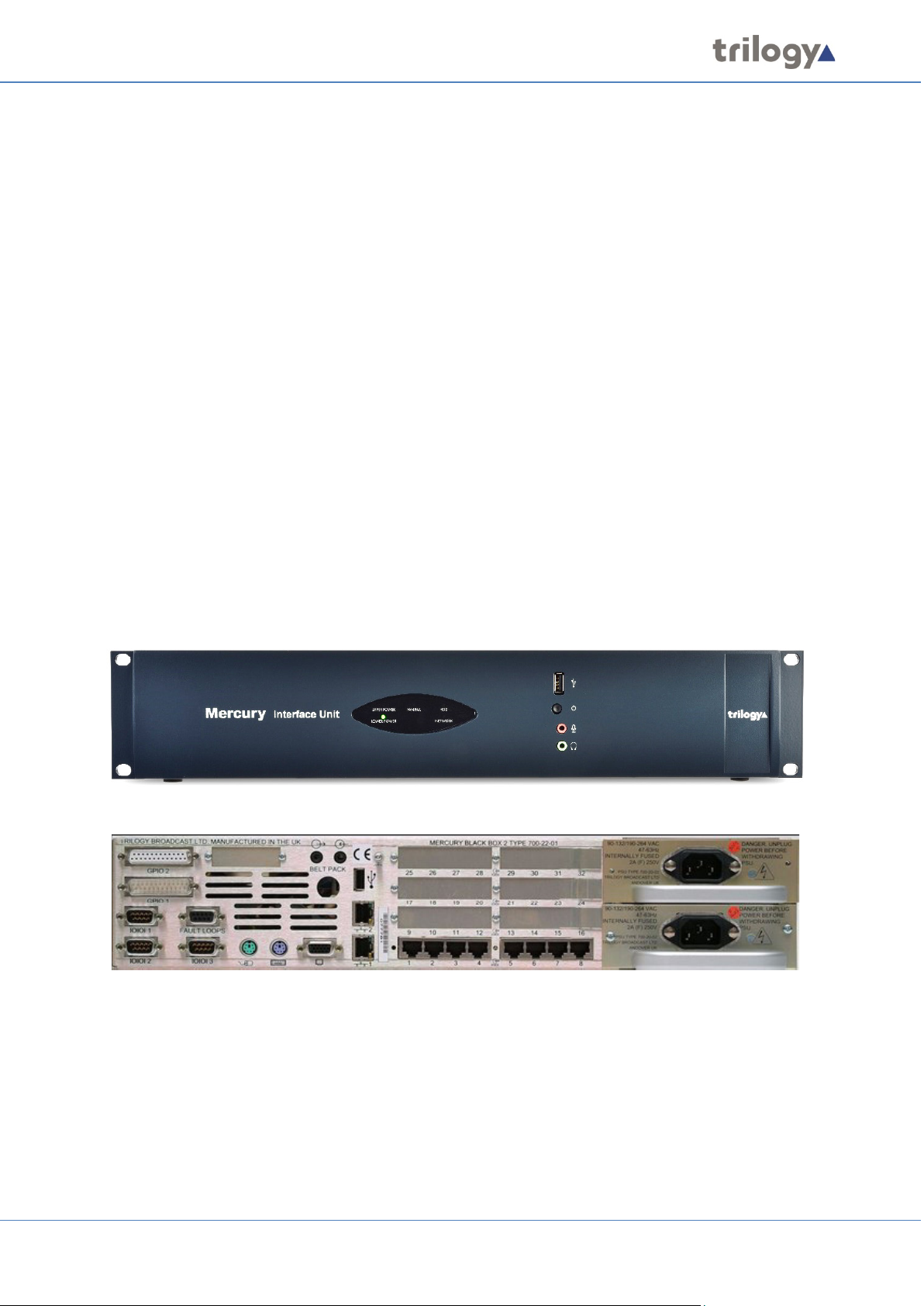
4. MERCURY INTERFACE UNIT (MIU)
4.1 OVERVIEW
The MIU offers the highest capacity of the available hosts. It acts as a versatile audio processing unit
and Voice over Internet Protocol (VoIP) gateway which allows a wide range of external devices to be
connected.
These user interfaces and devices include:
• Mercury Virtual Panels
• Mercury Hardware Panels
• External 4-wire or 2-wire audio devices
• Radios
• Telephony equipment
• Recording and logging systems
• Interoperability with Session Initiation Protocol (SIP) and H.323 IP telephony devices
The MIU is a 2RU, 19-inch wide rack-mountable unit containing a power supply, Windows processor
board and Mercury card (the VoIP mixing engine). A second, redundant power supply may be added
if desired. Each MIU can fit up to four expansion boards, each with four or eight ports (dependent on
type) in addition to two built-in ports, giving a maximum capacity of 34 ports in a single unit (when
four audio expansion boards are installed in an MIU). Note that these expansion boards can be
mixed and matched within an MIU, as required.
4.2 MIU VERSIONS
The following two MIU variants are covered in this User Guide:
• 700-25-06 - only available with Windows 10 Operating System.
• 700-25-04 - with Operating System Windows 7 or Windows 10.
The OS of earlier versions of the MIU cannot be upgraded but it may be possible to include such
hardware as part of a communications network. Please contact Trilogy for more information.
Page 18 of 338 Trilogy Communications
Page 19

Mercury Core
4.3 EXPANSION OPTIONS
Key options include:
• 8 port Audio Expansion Board (AEB)
• 8 port Radio Interoperability Board (RIB)
• 4 port Telephone Interface Board (TEB) types
• Foreign Exchange Office (FXO)
• Foreign Exchange Station (FXS)
• Ear and Mouth (E&M)
In addition to the four expansion slots, in the 700-25-04 MIU only, there is provision for other cards
to be added, which further enhances the capacity and flexibility of the MIU:
• General Purpose Interface (GPI) Board 700-12-01.
• Digital Signal Processing (DSP) Expansion Module 700-13-03.
The latest MIU, 700-25-06, has built-in GPI and DSP, provided on the internal PCI card so the GPI and
DSP options are not applicable. See sections 31 and 32 for connector pin-outs and specifications.
For the latest information on available options, please contact your supplier.
4.4 INSTALLATION PREREQUISITES AND REQUIREMENTS
The MIU is a 19-inch rack mounting format unit (2RU) which contains a Power Supply Unit (PSU),
processor board and Mercury PCI card. An additional redundant PSU can be fitted if required.
To install an MIU you will need:
• One International Electrotechnical Commission (IEC) mains cable for each PSU in the
MIU (maximum two).
• Keyboard, mouse and monitor if setting up the MIU for the first time. An SVGA monitor
capable of displaying at least 800 x 600 resolution is suggested.
• A single RJ45 network connector for connecting the MIU to its peers and the Database
Supervisor over TCP/IP.
• Any custom cabling for applications, including radio interfacing or audio 4-wire ports.
• Custom GPI cabling for external GPI interfacing if required.
• Telephone handsets for connection to the shared ports on TEBs if fitted.
• Telephone cabling for connecting TEB boards to a local or remote Private Automatic
Branch Exchange (PABX) if fitted.
• Appropriate tools if expansion boards are to be fitted.
Page 19 of 338 Trilogy Communications
Page 20
Mercury Core
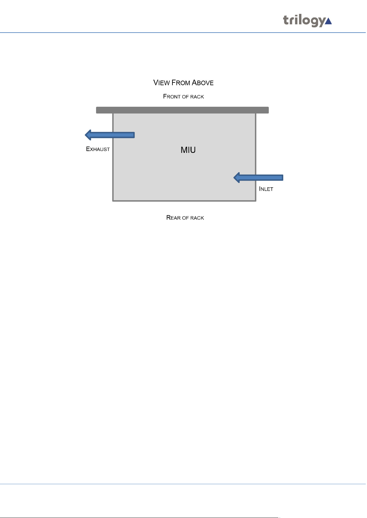
4.5 RACK MOUNTING
The MIU is 19” rack-mounted and occupies 2U. The depth (excluding mating connectors) is 375 mm.
Care should be taken with cooling and ventilation within the equipment bay. The air inlet is on the
right side of the chassis, towards the rear, as viewed from behind. The air outlet is on the left side,
close to the front. Take care not to obscure the vents. Refer to the image above or contact Trilogy
for further details.
4.6 CONNECTIONS
1. Connect a monitor, mouse and keyboard to the SVGA and PS2 / USB sockets on the MIU.
These are required only for the initial set-up of the MIU.
2. Connect the subscribers to the expansion board ports on the back of the MIU.
3. Insert one or more power cable(s) into the power socket(s) and connect the other end to a
mains supply.
4. The lower RJ45 network socket (“1”) on the back of the MIU is connected to the IP network.
It is important to configure the MIU IP address(es) correctly before making this connection
to avoid any possible network IP address conflicts. See the information below concerning
the internal network switch.
4.7 INTERNAL NETWORK SWITCH
A set of switches on the internal PCI riser board allows the internal network switch to be bypassed.
Default Mode
The MIU provides a single combined network connection via the lower RJ45 connection on the rear
panel (labelled “1”). To enable this mode, the internal switches are all set towards the front panel.
Alternate Mode
If all the internal switches are set towards the rear panel, then two physical network connections are
required.
• The upper connector labelled “2” is to the system motherboard network interface.
• The Mercury card interfaces via the lower connector labelled “1”.
Page 20 of 338 Trilogy Communications
Page 21
Mercury Core
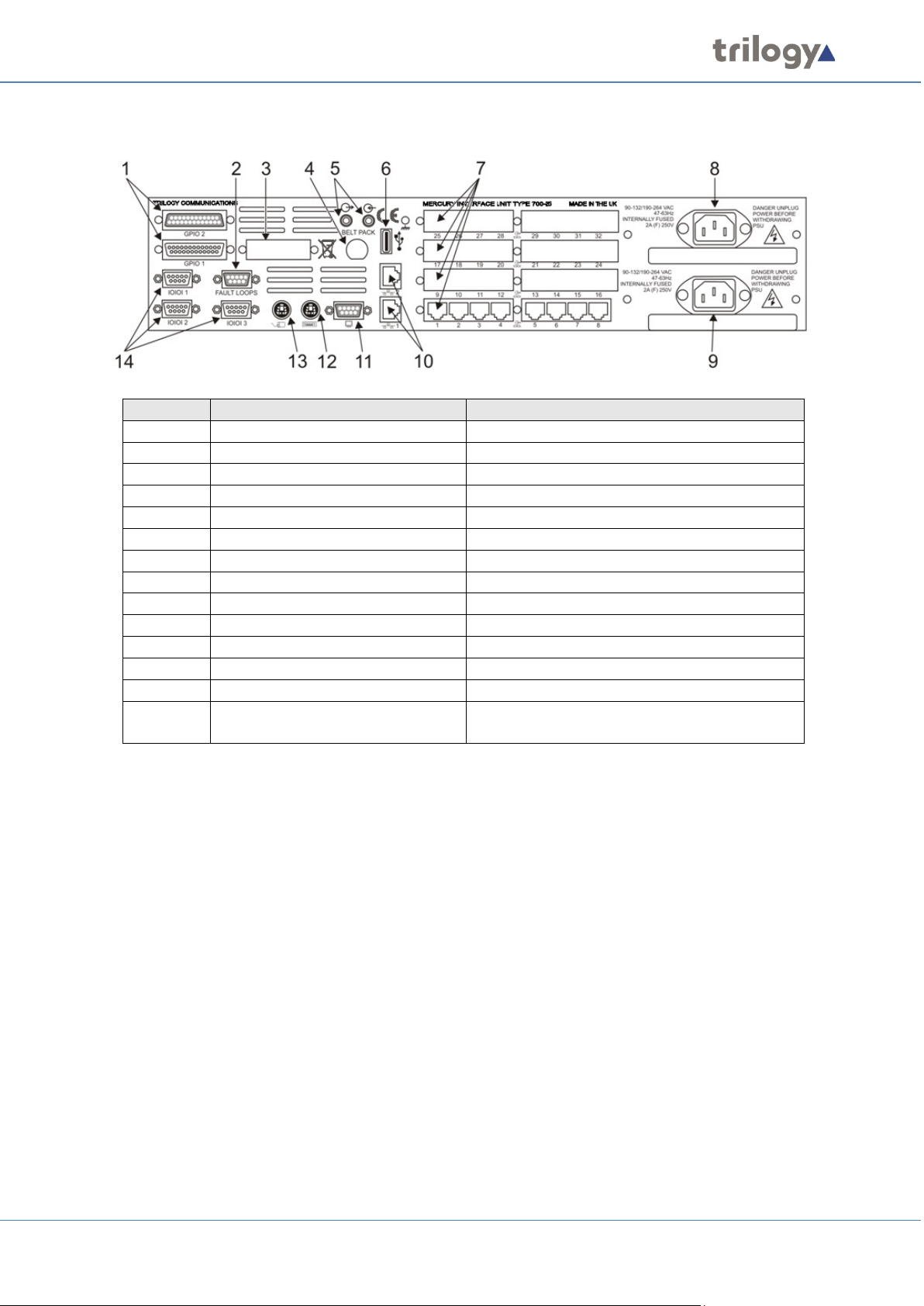
4.8 REAR PANEL DETAIL
Item
Description
Control/connector type
1
GPIO 2 & GPIO 1
D25
2
Fault Loops
D9 female
3
Camera Mix Board (Optional)
4 Belt Pack (Optional)
5 Sound card audio
3.5 mm Jack socket.
6
USB
Standard USB Series A socket.
7
Expansion Boards
Up to four (4) boards may be fitted.
8
Second Mains Input
IEC 9 First Mains Input
IEC
10
Network 1 and 2
RJ45 8P8C; 10/100Base-TX.
11
Monitor SVGA
D15 high-density female.
12
Keyboard
PS/2.
13
Mouse
PS/2.
14
Serial
Three (3) serial ports; two (2) RS232 and one
(1) RS232/422 on D9 male connectors.
See sections 31 and 32– Technical Data for connector pin-outs and specification.
Page 21 of 338 Trilogy Communications
Page 22
Mercury Core
Item
Description
1
System status LED
2
Audio loudspeaker connector (3.5 mm Jack socket)
3
USB 2.0 (currently disabled)
4
Shutdown / Restart button
5
System operation/Input power status LED (green/red)
6
Software status LED (green/red)
7
Network link status LED (yellow)
8
Indicator: not used
9
Audio headphone connector (3.5 mm Jack socket)
5. MERCURY COMMUNICATOR UNIT (MCU)
5.1 OVERVIEW
The Mercury Communicator Unit (MCU) is a powerful operator station with a peer-to-peer
architecture that enables the device to function independently. It can be either powered locally or
through Power over Ethernet (PoE), and it connects to interfaces including a virtual panel, headsets,
GPIs for PTT and auxiliary line-level stereo inputs.
5.2 STANDARD INDICATORS, CONTROL AND CONNECTORS (FRONT)
Page 22 of 338 Trilogy Communications
Page 23
Mercury Core
System status LED:
• Flashing - Power button has been pressed and the unit is waiting for Windows to
shutdown OR temperature has exceeded set limit (default 70⁰C) OR firmware upgrade is
in progress
• Red – Initial state (before connection with TBC)
• Off – Connection made with TBC
Audio connectors – Two 3.5 mm stereo jack connectors:
• Secondary microphone input
• Secondary headphone output
USB connector: USB 2.0 Type A female connector used to upload security certification codes.
Pushbutton switch (recessed): Provides system shutdown.
System Operation/Input Power Status LED:
• Green – Normal operation with correct DC input voltage present
• Red – Standby operation with correct DC input voltage present
• Off – No power present
Software status LED:
• Green – Network connection made after Talkback Controller (TBC) configuration load
• Yellow – Connection made with TBC
• Red – Initial state (before connection with TBC)
• Off – Firmware is non-operational
Network link status LED (RJ45 or SFP):
• Yellow – Network link present
• Flashing – Network link present, and actively transmitting or receiving
• Off – No network link present
5.3 STANDARD INDICATORS, CONTROLS AND CONNECTORS (REAR)
Page 23 of 338 Trilogy Communications
Page 24

Mercury Core
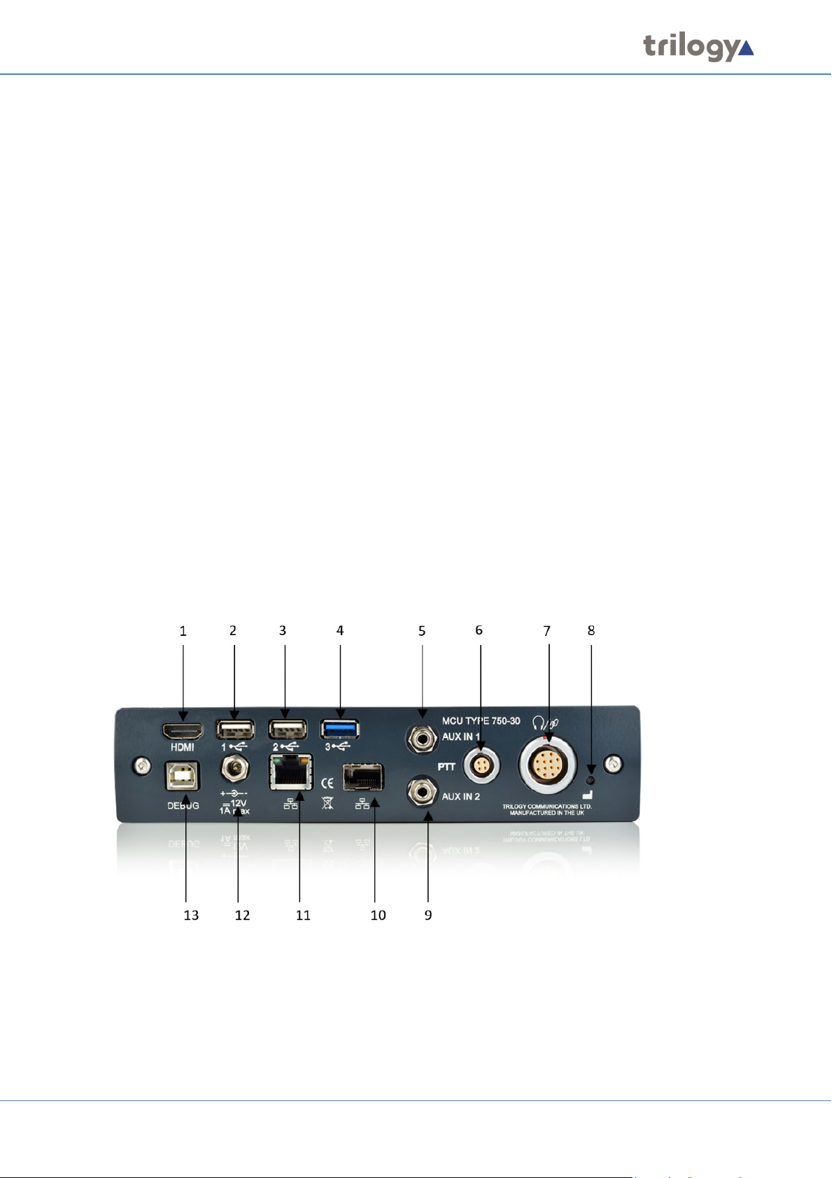
Item
Description
1
Video output – HDMI Type A
2,3,4
USB Type A
5
Audio input channel 1 - 3.5mm stereo jack connector
6
Auxiliary PTT – Lemo 4-pin connector
7
Customer Interface Adapter (CIA) – Lemo 12-pin connector used to
connect a dynamic headset, PTT and GPIO
8
Factory reset button (recessed): restores the default configuration
9
Audio input channel 2 - 3.5mm stereo jack connector
10
Network connector
11
Gigabit Network
12
Power connector – 2.5 mm DC jack connector
13
SPY Debug USB – USB 2.0 Type B female connector
5.4 INSTALLATION REQUIREMENTS
The MCU contains a Power Supply Unit (PSU), processor board and audio card. The MCU may be
freestanding or installed under a desk. For the latter arrangement, the mounting bracket is fitted to
the underside of the desk using self-tapping screws. The MCU then slides into the bracket from the
front.
To install an MCU you will need:
• One International Electrotechnical Commission (IEC) mains cable.
• USB keyboard and mouse if setting up the MCU for the first time.
• An HDMI monitor capable of displaying at least 800 x 600 resolution.
A single network connector for connecting the MCU to its peers and the Database Supervisor over
TCP/IP.
5.5 CONNECTING THE MCU
1. The MCU can be freestanding or installed under a desk.
2. Connect a monitor, mouse and keyboard to the HDMI and USB sockets on the back of the
MCU. These are required only for the initial set-up of the MCU.
3. Connect the headsets to the connectors on the front of the MCU. Three MCU variants are
available allowing different headsets to be connected.
4. Insert a power cable into the power socket and connect the other end to a mains supply.
5. The RJ45 network socket on the back of the MCU is connected to the IP network. It is
important to configure the MCU IP address(es) correctly before making this connection to
avoid any possible network IP address conflicts.
Full details of connections and specification are in section 34 - Technical Data | MCU | 700-30-00.
Page 24 of 338 Trilogy Communications
Page 25

Mercury Core
6. MERCURY SOFTWARE AND INSTALLATION
6.1 OVERVIEW AND CONCEPTS
The Mercury software suite comprises several individual software components which are packaged
and presented in a single software installer. Components required for a particular situation may be
selected either from a preset scenario or by selecting components individually for a custom
installation.
Mercury host hardware is supplied with all software pre-installed but the instructions in this section
may be used to assist should a reinstallation be required.
The key software installation task for an administrator is to set up the database and configurations
editor. Careful consideration should be given to the hardware requirements and settings required to
complete this. Please read section 7 before commencing installation.
The installer is also used to update an existing installation. When the installer runs, it checks for any
existing installed components and advises if more up to date versions are available. The update
process proceeds into steps whereby the existing installation is removed and then a reinstallation is
completed. During this process, you will be presented with the option to either remove or retain
existing settings: for security, the presented default is to remove settings.
The installer may also be used to add additional components to an existing installation, but it cannot
be used to remove components. If for any reason you wish to remove components from an existing
installation, you must first uninstall completely and start again.
NOTE: The Installer requests elevated permissions when it runs, so you can only install as an
administrator; therefore, everything is installed with the correct level of permissions and can be
installed into any directory.
Page 25 of 338 Trilogy Communications
Page 26

Mercury Core
Component
Description
Gateway
Configuration Editor
The Configuration Editor is used to model and implement the structure of
your Mercury system.
Database Supervisor
The Mercury database holds the Master configuration for all domains
components – Windows service and lightweight GUI.
Virtual Panel Web
The Virtual Panel Web Server is a middleware application used to
and lightweight GUI.
Gemini Software
The current software and firmware for the Gemini host. This may or may
ready for future use.
TBC (Talkback
The TBC application, installed on each Mercury host, manages all the
the “Startup” menu folder.
Virtual Panel
The Virtual Panel provides users with a single control panel from which
across security levels and domains to conduct voice communications.
Panel Software
The current software for IRIS panels. During installation, files are copied
to a location on the PC, ready for future use.
Tools
Tools are intended for use exclusively by System Administrators and are
configuration database.
6.2 MERCURY SOFTWARE COMPONENTS
The table below lists the range of software components included with the Mercury software
installer. There is a brief description of each component.
and hosts on the Mercury system. The database is managed by the
Mercury DB Supervisor application. This is a middleware application that
provides an interface between the database and the Mercury software
running on the hosts. Like the TBC (below) it also comprises two
Server
Controller)
connect the Talkback Controller (TBC) to one or more Virtual Panels. Like
the TBC (below) it also comprises two components – Windows service
not be different from that provided with a previous product build, so
please check version numbers before attempting to carry out an
upgrade. During installation, files are copied to a location on the PC,
audio routes in real-time for Mercury hosts connected over IP. The
application is made up of two parts:
• A Windows service which starts automatically when the host
boots.
• A graphical component (GUI) which allows status monitoring of
the TBC. This is a Windows executable (exe) which starts when a
user is logged on to Windows. This is controlled by a shortcut in
they can communicate with other users in their security enclave or reach
designed to check, validate and repair specific aspects of the
During installation, select components as appropriate. The following sections outline two typical
scenarios:
• Section 6.3 - Installation Procedure: Configuration Editor with Served Database. This would
normally be the administration PC for a Mercury system.
• Section 6.4 - Installation Procedure: Mercury Host with Virtual Panels. This applies to all Host
types but is only required if software re-installation is necessary.
Page 26 of 338 Trilogy Communications
Page 27
Mercury Core
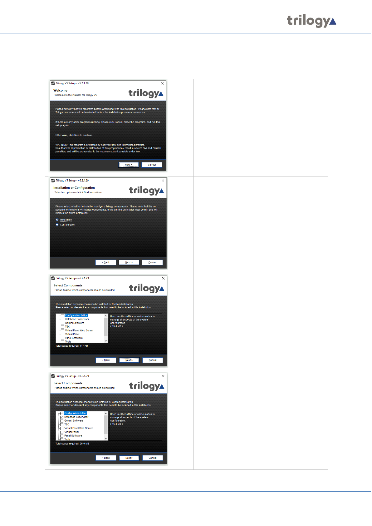
6.3 INSTALLATION PROCEDURE: CONFIGURATION EDITOR WITH SERVED DATABASE
Run the Mercury Installation Program. The Welcome screen appears:
Press Next to commence.
This screen will only appear if you have
previously installed Mercury components.
Make sure the Installation radio button is
selected.
Press Next to continue.
The Custom Installation screen now shows
all available components. For a new
installation, none are marked.
Press Next to continue.
Two components have been selected:
• Gateway Configuration Editor
• Database Supervisor
Press Next to continue.
Page 27 of 338 Trilogy Communications
Page 28
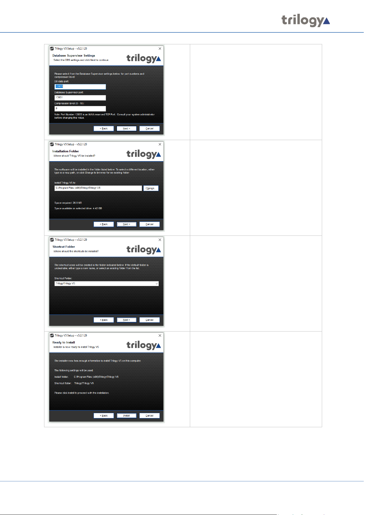
Mercury Core
Change the DB Supervisor Settings, if
required. Consult your System Administrator
before changing these settings.
Press Next to continue.
Select the Installation Folder. This is pre-set
but can be changed if components have not
already been installed.
Press Next to continue.
Select the Shortcut Folder. Again, this folder
is pre-set but can be changed, if required if
components have not already been installed.
Press Next to continue.
Review the settings you have selected, and
then press Install to begin copying files.
Page 28 of 338 Trilogy Communications
Page 29
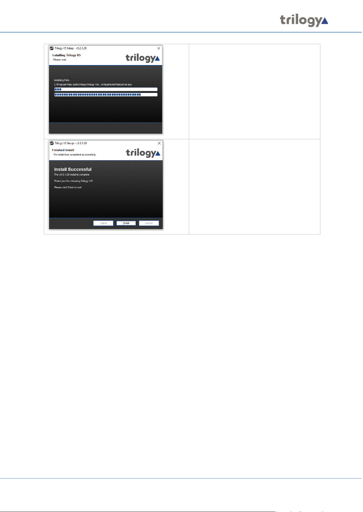
Mercury Core
The progress bars indicate that files are being
copied to destination folders.
Press Finish to close the Mercury Installation.
Page 29 of 338 Trilogy Communications
Page 30
Mercury Core
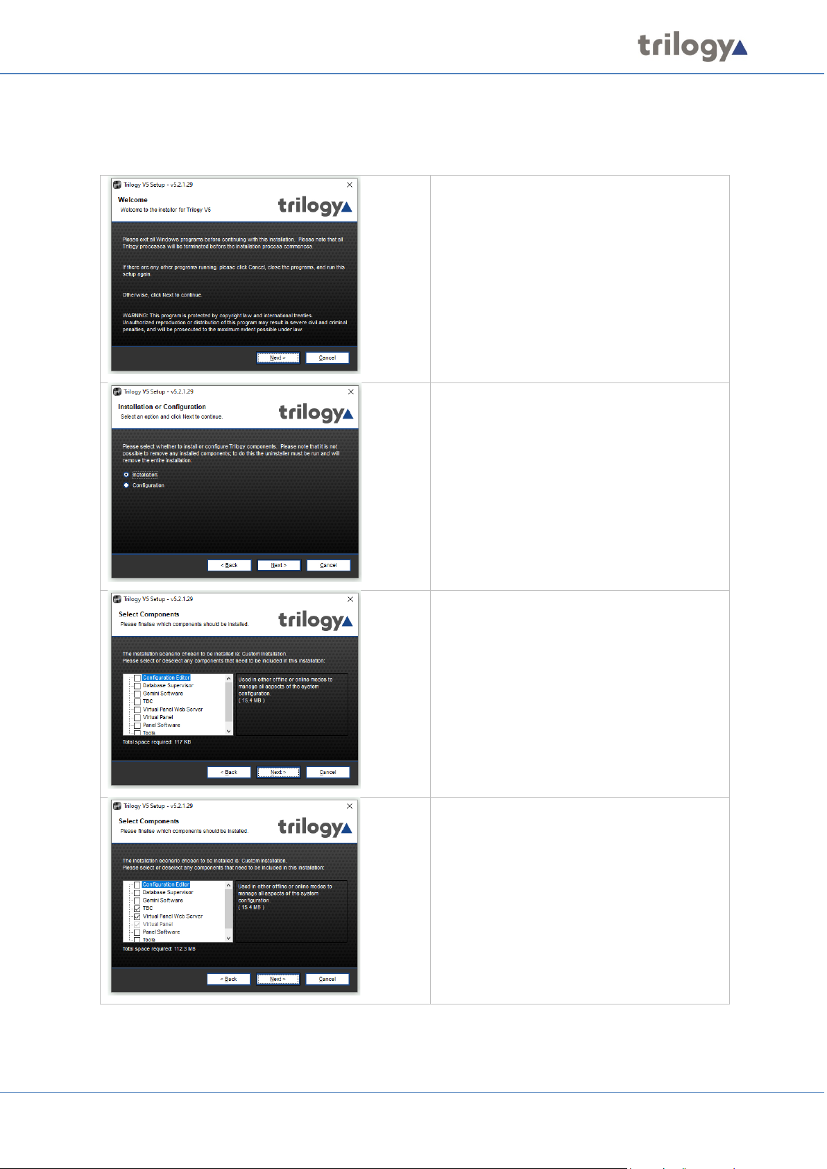
6.4 INSTALLATION PROCEDURE: MERCURY HOST WITH VIRTUAL PANELS
Run the Mercury Installation Program. The Welcome screen appears:
Press Next to commence.
This screen will only appear if you have
previously installed Mercury components.
Make sure the Installation radio button is
selected.
Press Next to continue.
The Custom Installation screen now shows
all available components. For a new
installation, none are marked.
Press Next to continue.
Two components have been selected:
• TBC
• Virtual Panel Web Server (including
Virtual Panel)
Press Next to continue.
Page 30 of 338 Trilogy Communications
Page 31

Mercury Core
Select the Host Type, Domain ID and Host ID.
The Domain and Host IDs make up part of the
Enterprise Domain Host Subscriber (EDHS)
address.
Press Next to continue.
Set the subscriber ID of the virtual panel. The
virtual panel subscriber ID defaults to the
internal audio port of the hardware. This is
usually two ports higher than the number of
physical ports fitted to the hardware. For
example, with an 8 port MIU (single AEB),
this would be set as shown to “10”.
Press Next to continue.
Enter the Hostname or IP Address of the
database location.
Press Next to continue.
Consult your System Administrator before
changing these settings. These settings will
be applied to local components (e.g. TBC and
VP Web Server) and must match those used
when the Database was installed.
Press Next to continue.
Page 31 of 338 Trilogy Communications
Page 32

Mercury Core
Enter the TCP port value for the Virtual Panel
Web Server.
Press Next to continue.
Select the Installation Folder. This is pre-set
but can be changed if components have not
already been installed.
Press Next to continue.
Select the Shortcut Folder. Again, this folder
is pre-set but can be changed, if required if
components have not already been installed.
Press Next to continue.
Review the settings you have selected, and
then press Install to begin copying files.
Page 32 of 338 Trilogy Communications
Page 33

Mercury Core
The progress bars indicate that files are being
copied to destination folders.
The installation has successfully completed.
Press Finish to close the Mercury Installation
Program.
Page 33 of 338 Trilogy Communications
Page 34

Mercury Core
6.5 SOFTWARE UPGRADE
The Mercury software installer may also be used to upgrade an existing installation. When the
installer runs, it checks for any current installation and performs a version check. If the current
version is out of date, an upgrade may be carried out.
Press Yes to continue.
Press Next to continue.
Data entered during the original installation
is held locally on each host. At this stage, you
can decide whether to delete or reuse such
data. For a software upgrade, the box is
normally left unchecked.
Press Next to continue.
Press Uninstall to continue.
Page 34 of 338 Trilogy Communications
Page 35

Mercury Core
The uninstallation phase is now complete.
Press Finish to move to the 2nd phase where
the software will be replaced with the new
version.
Please select whether to perform a Quick or
Customised upgrade. A quick upgrade will
use the settings from your previous
installation whereas a customised upgrade
will allow you to change the settings before
installation. For a software version upgrade,
the Quick option is the normal choice.
Press Next to continue.
The progress bars indicate that files are being
copied to destination folders.
The upgrade has successfully completed.
Press Finish to close the Mercury Installation
Program.
Page 35 of 338 Trilogy Communications
Page 36

Mercury Core
The process now follows the Installation Procedures described in previous sections.
6.6 ADDING ADDITIONAL MERCURY SOFTWARE COMPONENTS
NOTE: the installer cannot be used to remove individual Mercury components. To do this, all existing
components must be uninstalled and then a new installation carried out.
Run the Mercury Installation Program. The Welcome screen appears:
Press Next to commence.
Make sure the Installation radio button is
selected.
Press Next to continue.
The Custom Installation screen now shows
all available components. Existing
components are marked: select additional
components as required.
Press Next to continue.
Page 36 of 338 Trilogy Communications
Page 37

Mercury Core
The progress bars indicate that files are being
copied to destination folders.
Press Finish to close the Mercury Installation.
6.7 UNINSTALLATION PROCEDURE
An uninstall tool is included, alongside the installer. A shortcut to launch the uninstaller will be found
in the Windows Start menu, listed under Trilogy. If you cannot find the shortcut, type “Add or
Remove Programs” into the Windows search bar, then find Trilogy Mercury V5 from the list.
For the uninstall steps, see the first part of section 6.5 Software Upgrade on page 34. If you do not
intend to replace the software, then check the box “Remove Application Data”.
6.8 FIREWALL
Following the installation of the software as described above it will be necessary to open several
ports on the computer firewall. It is beyond the scope of this document to describe in detail how to
do this due to the range of operating systems, use of Windows or third-party firewall applications,
and the different permissions which may be granted to Windows users or administrators.
The most common scenario is the Windows firewall, and this requires the following rules to be
added for inbound ports:
• TCP 12005
• TCP 12006
• TCP 13001
Please contact your IT Administrator or Trilogy Technical Support for further assistance.
Page 37 of 338 Trilogy Communications
Page 38

Mercury Core
7. DATABASE AND THE DATABASE SUPERVISOR
7.1 OVERVIEW AND CONCEPTS
The Mercury database holds the Master configuration for all domains and hosts on the Mercury
system. The configuration details in the database are managed using the Configuration Editor, an
application that provides a Graphical User Interface (GUI) to visualize and interact with the database.
Any changes to the configuration are saved to the database and these changes are then retrieved by
each host in the Mercury system individually.
The database is managed by the Mercury DB Supervisor application. This is a middleware application
that provides an interface between the database and the Mercury software suite running on the
hosts.
The database itself can reside on any Windows
PC. The Supervisor is normally on the same PC
as the database files. See below for more
guidance.
The client applications exist on the individual
hosts.
A Mercury system can only have one database, which contains the source files that define the
configuration of the entire Mercury system. If part of the system needs updating, such as a function
change on one of the panels, the Configuration Editor is used to make the change and update the
database. The changed database configuration is then disseminated to each host in the system over
open database connections and cached locally. The changes are then (or later, at a convenient time)
made active on each recipient host (i.e. the working files on the host are replaced with the revised,
cached version).
When this sequence is complete and the revised configuration is operating correctly, the
Configuration Editor may be closed. Furthermore, the database may also be shut down or
disconnected since all hosts are running from their local cache. However, hosts will (correctly)
display a warning message, advising that connection to the database has been lost.
7.2 MERCURY DATABASE
Regardless of the scale of the system, from single MIU to multi-site, there must only be one instance
of the database. An important aspect of planning is to consider the correct location of the database.
On delivery, every MIU has the database pre-installed, which allows it to start and run cleanly during
the setup phase. For anything other than a single or small MIU based system, a different approach is
needed, and some guidelines are offered below. It is not recommended to install the Gateway
Configuration Editor on an MIU.
Page 38 of 338 Trilogy Communications
Page 39

Mercury Core
Scale of system
Database
Single MIU
Yes
Small system, 3 or
fewer MIU (Note 1)
Yes
Larger system, 4 MIU or
more (Note 2)
No
Note 1 -- The database must only be active on one
Minimum
Recommended
Application
----- Served Database plus Configuration Editor -----
OS
Windows 7
Windows 10 (64-bit pref.)/ Windows Server 2012
CPU
2 GHz
2 GHz
RAM
2 GB
8 GB
HDD space
100 MB
100 MB
MIU: any other MIUs should have the database
disabled or removed, and then connect as clients to
the single database.
Note 2 -- As the database increases in size and
complexity it will place additional demands on the
platform. For 4 or more hosts we suggest a separate
7.3 DATABASE INSTALLATION
The database should ideally be installed on a separate, fast PC on the network. If the system that
you are installing has many users, you should consider installing the database on a Windows-based
server. The database may reside on an MIU host for “small” systems, which are defined as having
three or fewer hosts. However, the Configuration Editor will not run on an MIU due to memory and
graphics limitations.
The main database component is the Mercury DB Supervisor which always runs as a Windows
Service. The database is administered using the Mercury DB Supervisor GUI. This application
automatically starts when you start Windows on the PC or server. The database [service] will
continue to run without interruption if the GUI application is shutdown.
You will see a Mercury DB Supervisor icon in the system tray. Right-click on this icon and select
Restore to open the Mercury DB Supervisor GUI. The Mercury DB Supervisor can be suspended or
resumed from this form if required. This action does not stop/start the underlying Windows service.
Full installation details are provided in section 6 - Mercury Software and Installation.
7.4 DATABASE PC/SERVER – SPECIFICATIONS
PC or rack-mounted server, with all hosts connecting
as clients.
Page 39 of 338 Trilogy Communications
Page 40

Mercury Core
7.5 MERCURY DB SUPERVISOR
The Mercury DB Supervisor comprises two components:
• Windows service which starts automatically on startup.
• GUI application which also runs automatically from a shortcut placed in the Windows
Start-Up folder during installation and is normally minimized to the System Tray.
The GUI application is used by the System Administrator to:
• View a list of connected Mercury clients (see page 41).
• View and manage database sessions (see page 42).
• View a log of events (for example, starting and stopping the service, connecting and
disconnecting clients) (see page 42).
• Specify database settings (see page 42).
When the GUI is running, a small additional icon (left) is
displayed in the Windows system tray. On double-clicking
the icon, the Database Supervisor GUI is displayed.
Normally, you will not have to make any changes to the settings, but if you do you must ensure that
you also update the Database Settings in the Configuration Editor.
The Mercury DB Supervisor GUI provides visibility of the Mercury database; if it is shut down you will
not be able to view the database and make changes to your database settings. If the Mercury DB
Supervisor GUI is shut down, the database itself is still running as a service and the communication
system will function as normal.
Closing and Restoring the Mercury DB Supervisor GUI
The Mercury DB Supervisor GUI application will be started automatically, via a shortcut to the
application in the Windows Start-Up menu, added during installation.
Closing the Mercury DB Supervisor GUI application does not affect the Mercury database which
always runs as a Windows service. The Mercury DB Supervisor GUI icon always appears in the system
tray and the GUI may be displayed by right-clicking the icon and selecting Restore.
NOTE: If inadvertently shut down, to re-start the Mercury DB Supervisor GUI application, click on
Database Supervisor in the Windows Start-up menu.
Mercury DB Supervisor GUI Status Indicator
An indicator in the bottom left corner of the GUI form shows the current status.
Page 40 of 338 Trilogy Communications
Database Supervisor is running correctly.
Database Supervisor is not running. Either it has been
suspended or the Windows Service has not started.
Page 41

Mercury Core
Server Menu
Menu Option
Description
Load Configuration
This allows a Mercury configuration file which has been created elsewhere,
Gateway Configuration Editor.
Change IP Address
This feature is no longer supported.
Start/Stop
Suspend or Resume operation of the Supervisor. The current status is shown
action does not start or stop the underlying Windows service.
Close
Closes the DB Supervisor GUI and minimizes it to the system tray. This does
will be maintained without disruption.
Shutdown
Shuts down the DB Supervisor GUI only. This does not affect the operation of
disruption.
Help Menu
Menu Option
Description
About
Displays version information.
The Clients tab is selected by default.
7.5.1 Mercury DB Supervisor GUI Menu Options
The Mercury DB Supervisor GUI menu options are as follows:
to be “pushed” to all currently connected database clients without using
Supervisor
by the indicator – see above. While stopped, all clients will be disconnected
which may cause unexpected results, requiring clients to be restarted. This
not affect the operation of the Database Supervisor Service: all connections
the Database Supervisor Service: all connections will be maintained without
7.5.2 Mercury DB Supervisor Clients
The Mercury DB Supervisor – Clients tab shows a list of active Mercury clients. Refer to section 7.6.1
for a description of the information on this tab.
To view a list of Mercury clients:
Right-click on the Mercury DB Supervisor icon in the system tray and select Restore to display the
Mercury DB Supervisor.
Page 41 of 338 Trilogy Communications
Refer to section 7.6 - Mercury DB
Supervisor Field Definitions for a
description of the information on this
tab.
Page 42

Mercury Core
Click the Sessions tab to show the
Click the Log tab to view the current
7.5.3 Mercury DB Supervisor Database Sessions
The Mercury DB Supervisor – Sessions tab lists details of the user running the DB Server service.
• Session – A data transaction between the database and the client.
• Connection – A Transmission Control Protocol (TCP) connection between the Database
Server and the client. Can be host to multiple sessions.
To view database sessions:
Right-click on the Mercury DB Supervisor icon in the system tray and select Restore to display the
Mercury DB Supervisor.
User and Client IP Address for all
connected clients.
Refer to section 7.6 - Mercury DB
Supervisor Field Definitions for a
description of the information on
this tab.
7.5.4 Mercury DB Supervisor Log
The Mercury DB Supervisor – Log tab shows a list of all database-related events. These events
include initialization of the Database Server, Database Supervisor, configuration and client
connections.
Checking the log can provide useful information if you have problems connecting to the database.
To view, save and clear the log:
Right-click on the Mercury DB Supervisor icon in the system tray and select Restore to display the
Mercury DB Supervisor.
contents of the log.
Refer to section 7.6 - Mercury DB
Supervisor Field Definitions for a
description of the information on
this tab.
To clear the log, click the Clear
button.
Page 42 of 338 Trilogy Communications
Page 43

Mercury Core
Click the Settings tab to show the
Click the Advanced tab to make
7.5.5 Mercury DB Supervisor Settings
The Mercury DB Supervisor – Settings tab allows you to specify various parameters that control the
operation of the DB Supervisor and database.
NOTE: Ensure that you have closed all client applications before you apply any changes to the
Supervisor settings. To do this click Start / Stop on the Server menu of the Mercury DB Supervisor.
To change the DB Supervisor settings:
Right-click on the Mercury DB Supervisor icon in the system tray and select Restore to display the
Mercury DB Supervisor.
General settings for the DB
Supervisor.
Make the required changes.
Refer to section 7.6 - Mercury DB
Supervisor Field Definitions for a
description of the information on this
tab.
changes to the advanced settings, if
required.
Refer to section 7.6 - Mercury DB
Supervisor Field Definitions for a
description of the information on this
tab.
Click Apply to save the changes.
Page 43 of 338 Trilogy Communications
Page 44

Mercury Core
Display Item
Description
ID
Shows the ID of the connection. This is dynamically assigned by the DB Server
The ID cannot be changed manually.
Client IP
Shows the Internet Protocol (IP) address of the connected client.
Type
Shows the type of client connected.
EDHS
Shows the Enterprise Domain Host Subscriber (EDHS) address of the connected
The Configuration Editor displays as 0.0.0.0
Display Item
Description
User
Shows the name of the client user. For example, the operator name logged into
the Configuration Editor.
Client IP
Address
The IP address of the client that is ‘attached’ to the DB Supervisor.
Display Item
Description
Date/Time
The date and time of the log entry.
Message
The text of the message recorded in the log.
7.6 MERCURY DB SUPERVISOR FIELD DEFINITIONS
7.6.1 Mercury DB Supervisor – Clients tab
when a connection is established.
The ID usually starts at 1 and goes up in sequence. However, if a connection is
dropped the counter can roll back and use the dropped ID if one needs to be
reassigned.
client.
7.6.2 Mercury DB Supervisor – Sessions tab
7.6.3 Mercury DB Supervisor – Log tab
Page 44 of 338 Trilogy Communications
Page 45

Mercury Core
Field
Description
Data Location
Shows the path to the database files. Click to change this location if required
(NOT RECOMMENDED).
Interface
If the computer running the DB Server has two network cards, this setting allows
Default = Any.
DB Data Port
The IP port that the DB Master (or Slave) uses for data connections.
Default = 12005
DB Admin.
This is the port used by the Configuration Editor to access the DB Supervisor. The
Default = 12006
Supervisor
The IP port on which the Database Master (or Slave) listens for connection control
Default = 13001
7.6.4 Mercury DB Supervisor – Settings – General
the Administrator to choose the network interface from which the database will
run.
Changing this will set the DB Server to listen on the selected IP address.
Database clients must change their DB Server setting to this IP address to connect
to the database.
Changing the value changes the IP port number that the database accepts
incoming connections on. The value must be changed if:
IP Port 12005 is in use elsewhere on the network by another application.
Network security deems that another port is used, or Network Address
Translation /Port Address Translation (NAT/PAT) requires another port to be
used.
If this value is changed, all clients (including slaves) must be configured to connect
to the new port value.
Port
Port
value cannot be changed.
data.
Changing the value changes the IP port number that the database accepts
incoming connections on. This value needs changing if:
IP Port 13001 is in use elsewhere on the network by another application.
Network security deems that another port must be used, or NAT/PAT requires
another port to be used.
If this value is changed, all clients (including slaves) must be configured to connect
to the new port value.
Page 45 of 338 Trilogy Communications
Page 46

Mercury Core
Field
Description
Dead-session
The time it takes for a database transaction session to timeout upon client or
Default = 35 seconds. Maximum = 240 seconds. Minimum = 35 seconds.
Dead-session
The time interval between successive checks for dead sessions. It should only
Default = 10 seconds. Maximum = 60 seconds. Minimum = 5 seconds.
Max. dead sessions
The maximum number of dead sessions that can occur before dead sessions
Default = 10. Maximum = 50. Minimum = 1.
Connection timeout
The time allowed for an idle TCP/IP connection to timeout.
Default = 300 s. Maximum = 300 s. Minimum = 60 s.
Connections
The number of concurrent client connections the Supervisor can handle.
Default = 100. Maximum = 1000. Minimum = 1.
Dead Client Interval
Default 15 s, Maximum 120 s, Minimum 10 s.
Temp. directory
The Database Supervisor stores temporary files in this location.
Trilogy recommends you accept the default offered.
Cache Thread Start
Delay
Default = 100 ms
Min = 100 ms, Max = 1500 ms.
Max Cache Threads
Default = 10. Min = 1, Max = 50.
7.6.5 Mercury DB Supervisor – Settings – Advanced
timeout
interval
network failure. This should be left as the default setting.
Increasing the value in poor network conditions may help prevent premature
session timeouts.
This value should only be modified by an experienced Administrator.
be modified by experienced Administrators.
are pruned.
This should only be changed if there are a large number of concurrent
connections to the database.
The value can be increased in cases of poor network performance.
It should only be modified by experienced Administrators.
The value is in seconds.
Adjusting this will change the maximum number of clients that can connect
to a Database Server. This should not be changed unless there are many
client connections, and database errors are received in the Database Log
page and client application logs.
The DB Sessions tab lists the current connections to the Database Server and
gives a good indication should the maximum connection limit be approached.
Page 46 of 338 Trilogy Communications
Page 47

Mercury Core
8. CONFIGURATION EDITOR | BASICS
8.1 OVERVIEW
The Configuration Editor is used to model and implement the structure of your Mercury system. To
begin defining the structure and connectivity of the system, you need to put in place all the required
Domains, Conferences, Groups and IFBs that are required. This is done using the Enterprise Editor.
A unique addressing system is used in the Mercury system. This is known as the Enterprise Domain
Host Subscriber (EDHS) system. The host is the main element of the system. Subscribers make use of
the host's facilities to provide audio communications. Hosts are grouped into logical groups, called
domains. These are predominantly groupings of convenience, allowing a system to be segregated
into separate areas. There is a close analogy between this definition of domains and Internet
Protocol (IP) network domains, since it may be appropriate to run each area, or building, on a
different subnet.
The Enterprise level sits above the domains, allowing domains to be grouped into a larger entity.
Every host in the system has its own unique EDHS address which is assigned by the Configuration
Editor and entered during host installation. This makes it possible to cross-reference an EDHS
address to an IP address; while the IP address may change, but the EDHS remains constant. User
interfaces can be configured to allow communications between EDHS entities.
Once all basic objects have been defined in your Enterprise, you must then configure the domains
and add hosts using the Domain Editor. Subscribers can then be added to the defined hosts using the
Host Editor, while the host settings, including the IP addresses of the audio card and the host itself,
can be defined. Routes are added using the Routes Editor. These routes can be used when defining
General Purpose Input Output (GPIO) processes. Subscribers are configured using the Panel
Configuration Editor. The Conference Editor is used to specify members of a conference and to
define all the hosts that may need to take part in a conference at some time.
Once the complete configuration has been defined and saved, it is transferred to the hosts and the
subscribers on the system using open database connections. Uploading the settings sends them to
their destinations where they are cached. To make these changes active (i.e. replace the working
files with the cached version), you must instate or activate the changes. A configuration can be
changed at any time to reflect changes in the Enterprise and transferred to the hosts before being
instated or activated.
Page 47 of 338 Trilogy Communications
Page 48

Mercury Core
8.2 BEFORE YOU START
Typically, one computer is designated as the configuration management computer. Any changes that
are made to the configuration of the Enterprise using this computer are then transferred to all other
hosts within the Enterprise. Refer to the Mercury Database section in this User Guide for more
information on database configuration.
Unless a separate PC or server is specified to host the Mercury database, the configuration software
and database run on the same machine. The configuration software can, later, be installed on other
machines in the Enterprise, if required.
If you are running a ‘served’ Configuration Editor, you should always ensure that the Database
Supervisor software is running on the Master machine. This is installed as a service within Windows
and should, therefore, start automatically. You can check that the Database Supervisor is running as
follows:
• Look for the Database Supervisor icon in the system tray. Right-click on the icon and
choose Restore. If the supervisor is running, the indicator at the bottom left corner of
the form (next to the Trilogy logo) is green.
• If the indicator is red, see Mercury DB Supervisor on page 40.
8.3 INSTALLING THE CONFIGURATION EDITOR
The Configuration Editor is usually installed on the same PC as the database. However, it can also be
installed on other PCs on the network, if required. If you install the Configuration Editor on another
PC, you must provide the IP address or hostname of the PC that is running the database.
NOTE: We recommend that you read section 7 - Database and the Database Supervisor in this
manual before installing the database and the Configuration Editor.
8.3.1 Installation (Served Configuration Editor Scenario)
To install the database and Configuration Editor, please see Mercury Software and Installation,
section 6 of this manual.
8.4 CREATING A CONFIGURATION
The Configuration Editor provides you with a view on the underlying database tables and allows you
to add, delete and maintain records in the database.
To create a configuration that models your Enterprise:
• Make sure you understand the structure of your Enterprise in terms of domains so you can
create a plan that includes details of the hosts and subscribers in the Enterprise.
• Input the information from your plan using the Configuration Editor. The Configuration
Editor provides a logical tree view of the items that you need to configure. We recommend
that you start at the top level and work logically down through the various elements, such as
domains and groups, which together make up a configuration. The configuration can be
tested and deployed incrementally if required.
• Save the configuration information and transfer this to all destinations within your
Enterprise.
Page 48 of 338 Trilogy Communications
Page 49

Mercury Core
We recommend that you also place a shortcut to the Configuration Editor on the desktop
of the computer.
Database Supervisor is not running. Either it has
started.
8.5 USING THE CONFIGURATION EDITOR
8.5.1 Starting the Configuration Editor
To start the Configuration Editor, select it from the Program list, available on your Windows Start
menu: (Trilogy >> Mercury v5 >> Configuration Editor).
8.5.2 Software Features
When run for the first time, Gateway will prompt
you for a feature unlock code. The code is supplied
with your original purchase CD and you should
keep this safe for any future re-installation.
Additional paid-for features may be unlocked by
entering a new code.
8.5.3 Connecting to the database
If you are using a served Configuration Editor, you must ensure that the Mercury DB Supervisor is
running, and the location of the database is correct.
If not, you will see this message.
To verify that the Database Supervisor is running,
right-click on the icon in the System Tray and choose
Restore. Alternatively, double click the icon.
Check the indicator at the bottom left corner of the
dialogue.
Database Supervisor is running correctly.
Page 49 of 338 Trilogy Communications
been suspended or the Windows Service has not
Page 50

Mercury Core
If the database is running and the settings are
trilogy.
File
actions
Menu
Enterprise
System
Details
Version
When you have confirmed that the supervisor is
running, click Yes on the warning message to specify
the location of the database.
correct, you will be prompted to log in.
Enter the Operator and Password then click OK.
NOTE: Operator and Password are case-sensitive.
The default password for the Admin operator is
8.5.4 The Configuration Editor Interface
The Configuration Editor is divided into six main areas as shown below:
(gear icon)
info
Tree
Panel
Menu (Gear Icon)
Click on the gear icon to open the menu. Options let you create a new configuration, import or save
a configuration, set preferences and view specific parts of the Enterprise. The menu options are
described in detail later.
Version Info
This is the filename of the currently loaded configuration. If you “Save” the current configuration to
incorporate any changes, this is the file (and location) which will be used. The version number (v5.9
in the example) will increment each time changes are saved.
Enterprise Tree
The Enterprise tree shows an expandable view of the container objects that make up the entire
configuration.
A plus sign next to an item indicates that it can be expanded to show more items; a minus sign
indicates that it can be collapsed.
actions
Page 50 of 338 Trilogy Communications
Page 51

Mercury Core
Button
Description
Start a configuration upload, ensuring that all hosts are synchronised. Uploading the
settings sends them to their destinations where they are cached. Upload the settings
when you have completed or modified a configuration.
Restart (activates) configuration changes. The working files on each host are replaced
This button is not enabled if you are working with a local database.
The configuration has been changed.
The configuration upload is in progress.
Changes have been uploaded to hosts but not restarted.
The configuration is in the process of being restarted.
The configuration has been restarted.
Button
Description
Starts a new (empty) configuration. The current configuration will be lost unless you
Yes to continue.
Loads a previously saved configuration (.trilogy archive). The current configuration will
be overwritten. A warning is given: click Yes to continue.
Saves the current configuration to the current file and location. This can be loaded back
particularly before you upgrade the software.
Details Panel
If you select an item within the Enterprise tree, details of that item will be shown in the Details
panel. For example, select a domain from within the Enterprise tree to display a list of the hosts
specified for that domain, in the Details panel. Double-click an item in the Details panel to open an
Editor window and make changes.
System Actions
Descriptions of the Configuration Editor system action buttons are provided below.
with the cached versions. Note that this button may not be enabled if you have selected
to automatically instate settings.
Database Status Icon
The database status is shown in the System Actions area of the Configuration Editor main screen.
The icon is also a button which, when clicked, displays the Active Clients dialogue.
The icons are:
File Actions
Descriptions of the Configuration Editor file action buttons are provided below.
save it before creating a new configuration. A warning is given, and you need to click
into the Configuration Editor later if required. It is important to save a configuration,
8.5.5 Menu Options
The menu options accessed from the gear icon of the main Configuration Editor screen are detailed
in the following section. The top level has 6 entries, detailed below.
NOTE: The options will vary depending on whether you are using a local file system database or a
served database.
Page 51 of 338 Trilogy Communications
Page 52

Mercury Core
File
Option
Description
New
Starts a new (empty) configuration.
before creating a new configuration.
Load Configuration…
Loads a previously saved configuration.
The current configuration will be overwritten.
Save Configuration…
Saves the current configuration as a file to the current
This can be loaded back into Gateway later if required.
Save Configuration As…
Saves the current configuration as a file with a choice of
This can be loaded back into Gateway later if required.
Switch to Live Mode
Switches from the default “online” mode of operation
within Gateway.
Start Configuration Upload
Upload the current configuration data to all hosts. The
Note: upload is a background task.
Restart with Configuration
Restart the host(s), after upload. The host will restart
task.
Exit (Alt + F4)
Close the Configuration Editor.
View
Option
Description
Active Clients
Opens the Active Clients’ Status window.
Trilogy Positioning System
This option is not currently available.
Expand Configuration View
Expands all branches of the Enterprise tree.
Collapse Configuration View
Collapse all branches of the Enterprise tree.
Refresh Configuration View (F5)
Refresh the configuration view to reflect recent changes.
Configuration Search (F3)
Type the name of any entity within the configuration.
The current configuration will be lost unless you save it
location.
location.
(upload followed by a restart) to a “live” mode which
allows minor changes to be made without the need for a
restart. This is a paid-for option, enabled by keycode
Changes
data is cached at each host, pending the “restart”
command (see below). If the preference to “auto restart”
is checked, then upload and restart are seamlessly linked.
using the new (uploaded) data. Note: this is a disruptive
Highlight the result then click Launch to view that entity
in the main window.
Page 52 of 338 Trilogy Communications
Page 53

Mercury Core
Setup
Option
Description
Database Settings…
Opens the Database Settings dialogue. Here you can
Database Supervisor.
Preferences…
Opens the Preferences dialogue. Here you can change
Configuration Editor.
Entity Filter…
To simplify the visual appearance of what can become a
purchased for your project.
Enter Software Keys…
Features within Gateway are unlocked using software
it here.
Tools
Option
Description
Recalculate All Conference Best
Select this option to recalculate the best profiles for
conferences in your Enterprise.
Configuration Gateway CE
Allows a previously saved configuration file to be
was last saved.
Launch Access Management
Console
Opens the Access Management console, used to manage
user roles and Administrators. See section 28.
Gemini Upgrade
Allows for bulk upgrades of multi-host systems (Gemini
only).
Change Password
Opens the Change Password dialogue. Use this option to
change your login password.
Window
Option
Description
Close Editor
Closes the currently open editor and returns the
application to the opening screen.
Help
Option
Description
About
Shows the version number of both the individual
application and the product.
change network settings, including the IP address of the
some of the settings that relate to the operation of the
complex GUI, unused entities may be hidden from view.
For example, control panel types which have not been
keys, purchased from Trilogy. To enable a feature not
currently activated, purchase an additional key and enter
Profiles
Version…
conferences.
This can take some time depending on the number of
selected and an information dialog displayed indicating
the Gateway version and date/time the configuration
Page 53 of 338 Trilogy Communications
Page 54

Mercury Core
Click Yes to confirm that you want to create a new
Click Cancel if you want to save or keep the current
page 55 for more information.
8.6 CONFIGURATION CREATION AND MANAGEMENT
You can create a new configuration at any time. However, if you do not save (archive) your current
configuration, all changes will be lost when you create a new configuration.
If you want to keep a configuration that you are working on (and possibly come back to later),
ensure that you save the configuration before you create a new one (refer to Saving and Loading
Configuration Settings on page 55 for more information).
NOTE: If you are using the Release Candidate Workflow, refer to page 62 for details of creating,
saving and loading configurations.
8.6.1 To create a new configuration
Click the Start a new empty configuration button .
The message (right) is shown.
NOTE: The message will not be shown if the current
configuration has previously been saved.
configuration. A progress bar will display while the new
configuration is created.
configuration.
Refer to
NOTE: A default configuration (or Enterprise) is created with a single domain and two conferences.
The Enterprise tree shows an expandable view on the configuration that has been created. The
name of the Enterprise includes the creation date. The configuration must be changed to match your
specific requirements.
Saving and Loading Configuration Settings on
Page 54 of 338 Trilogy Communications
Page 55

Mercury Core
A progress bar will display while the new configuration is loaded.
Click Cancel if you want to save or keep the current configuration.
8.6.2 Saving and Loading Configuration Settings
It is good practice to save a configuration, with the date and time that it was saved in the filename,
at various stages of its development. If you save a configuration regularly, you can load it back if you
need to.
Saving a Configuration
A configuration can be saved at any time.
NOTE: The configuration data is important, and we would recommend that you also copy it to
removable media or ensure that it is backed up with your other data.
To save a configuration:
• Click the Save… button .
• The Windows File Save… dialogue is displayed, with the filename and location set to the
values used at the previous Load operation.
• If this is the first “save” operation for a new configuration, enter a name for the
configuration file and select the folder into which you want to save the configuration.
• Click the Save button.
If you have previously saved a configuration with the same name in the specified folder, click Yes if
you wish to overwrite the old file.
Loading a Configuration
When you load a configuration, it will overwrite the currently loaded configuration.
To load a previously saved configuration:
Click Load… to load an existing configuration.
The message (right) is shown.
NOTE: The message will not be shown if the current
configuration has previously been saved.
Click Yes to confirm that you want to create a new
configuration. Browse for and select the
configuration that you want to load.
Page 55 of 338 Trilogy Communications
Page 56

Mercury Core
When the revised data has been transferred, you can choose whether to instate and go live with
the configuration or instate the changes later.
8.6.3 Uploading Configuration Data
Once you have completed developing your configuration, or have completed the details for a
specific host, you can send the changes to the hosts in your system, and subsequently to each
subscriber.
Uploading is the first stage of this process when data is transferred to all relevant hosts and cached.
To make these changes active during the second stage, (i.e. replace the working files with the cached
version), you must instate or activate the changes. Always keep in mind that although the first stage
happens in the background, the second stage is disruptive.
NOTE: An administrative setting, on a host-by-host basis, determines the priority of the database
cache processing to give control over the amount of CPU usage during an instate operation – this
minimizes the potential interruption to audio communications. Refer to the Configuration Editor –
Hosts and the Host Editor for more information on this setting.
Updating a Configuration
To update a configuration, ensure that you change your database settings so that you are working in
Served/Remote Database mode.
Click Upload . The process ensures that all hosts are synchronised.
The configuration update progress dialogue is
displayed.
If you press No, you can restart the system later by
clicking the yellow Restart button which will then
be enabled.
To restart with a new configuration:
Click Yes on the Mercury Config Editor dialogue
box or (later) click the Restart button .
The dialogue shows the progress of the update.
Configuration Update Messages
When you are updating a configuration the following message boxes may be displayed:
Page 56 of 338 Trilogy Communications
Page 57

Mercury Core
No active clients are running therefore
The configuration has been changed.
The configuration update is in progress.
Changes have been uploaded to hosts but not restarted.
The configuration is in the process of being restarted.
The configuration has been restarted.
update cannot take place.
Understanding the Status of a Configuration
The database icon which is shown in the top-right of the Configuration Editor window shows the
version of the database and its status.
NOTE: You can specify when the database version is incremented on the Database Management tab
in the Enterprise Editor and specify whether the version is incremented when a database is imported
into the Configuration Editor. Refer to the Configuration Editor – Enterprises and the Enterprise
Editor section in this User Guide for more details.
8.6.4 Active Clients
Best-practice is to monitor the upload and instate process closely using the Active Clients dialogue.
Refer to page 62 for more information.
8.6.5 Uploading and Instating on a Per-Host Basis
In addition to uploading and instating a configuration for all hosts on the system, you can upload and
instate hosts on an individual basis from the Active Clients window. Refer to page 62 for more
information.
Page 57 of 338 Trilogy Communications
Page 58

Mercury Core
8.7 DATABASE SETTINGS AND PREFERENCES
Once you have connected to the database, you will not usually have to change the database settings
provided that the IP address of the database machine does not change. If this is allocated by
Dynamic Host Control Protocol (DHCP), you may need to change the settings and specify the name
of the host PC should the IP address change.
NOTE: You can specify 127.0.0.1 in the IP address field if you want to use the Local Host.
8.7.1 Changing Database Settings
On the Setup menu, select Database Settings… to open the
dialogue.
• Make the required changes to the settings. Refer to section 8.11.1 for details of the
fields and settings.
• Click OK to save your settings.
If the settings are not correct, you
will receive an error:
• Click OK in this box and review the database settings. If you still cannot connect to the
database, ensure that the Database Supervisor is running and that the IP address or
hostname is correct. Also, check that no hardware or software firewall is preventing the
connection.
Page 58 of 338 Trilogy Communications
Page 59

Mercury Core
Connection to the local file system database is indicated by a change to the header
colour, from green to blue on Gateway, as shown below.
8.7.2 Using a Local Database
You can use a local database rather than connecting to a database on the network. If you do this,
you must also specify the same local database in the Supervisor Settings for the Talkback Controller
(TBC). Refer to Mercury Talkback Controller in section 29 of this User Guide for details.
A local database is used to develop the configuration when using the Release Candidate Workflow.
NOTE: If you have installed an Offline Configuration Editor, the local database setting will be selected
by default.
To use a local database:
• On the Setup menu, select Database Settings… to open the dialogue.
• Click Local Database. The following warning is displayed:
Click OK on this message to continue.
If necessary, specify the database folder. By
default, this is:
C:\ProgramData\Trilogy\Mercury
V5\ConfigurationEditor\DB
Click Browse to select a different output
folder for the local database.
Click OK and the Configuration Editor will
connect to the local files and prompt you to
log in.
Page 59 of 338 Trilogy Communications
Page 60

Mercury Core
8.7.3 Preferences
The connection preferences can be changed to allow individual customisation of the application. On
the Setup menu, select Preferences… to open the Preferences dialogue. There are three tabs, shown
below.
Refer to section 8.11.2 for details of settings
that can be changed.
Click OK to save the changes.
Refer to section 8.11.3 for details of settings
that can be changed.
Click OK to save the changes.
Refer to section 8.11.4 for details of settings
that can be changed.
Click OK to save the changes.
Page 60 of 338 Trilogy Communications
Page 61

Mercury Core
8.8 ADMINISTRATOR PASSWORD
The default password for the Admin user is trilogy.
Other Local Administrators may be created (see section 28 - Configuration Editor | Access
Management) and these will each have their password which can be changed using the Change
Password option.
8.8.1 Changing the Administrator Password
If security is an issue, you can change the Administrator Password to ensure that the configuration
cannot be accessed by unauthorised users.
To change the administrator password:
On the Gateway Tools menu, click Change Password. The Change Password dialogue is displayed.
Enter old and new passwords.
Re-enter the new password for confirmation.
Click OK.
IMPORTANT: If you change the Admin user password and subsequently cannot remember the new
one, you will need to reinstall the Database and Configuration Editor to reset the password back to
default.
Page 61 of 338 Trilogy Communications
Page 62

Mercury Core
8.9 ACTIVE CLIENTS
The Active Clients option, on the View menu, lets you view a list of hosts that are currently
connected to the database. These hosts will receive configuration updates if you carry out a
configuration update (see page 56).
NOTE: This option is not available if you are using an Offline Configuration Editor connected to a
local database.
8.9.1 Viewing Active Clients
Viewing active clients is also a useful troubleshooting tool since it shows:
• Hosts that are currently connected to the Mercury system.
• The configuration version that attached hosts are running.
• Whether the configuration is loaded and current.
• The EDHS address of each connected host.
• The IP address of each connected host.
To view active clients:
• On the View menu, click Active Clients to open the Active Clients’ Status window.
8.9.2 Uploading and Restarting Active Clients
You can upload and restart hosts on an individual basis from the Active Clients window.
To upload and restart active clients:
• On the View menu, click Active Clients to open the Active Clients’ Status window.
• Use the checkboxes adjacent to each Client and check/uncheck as appropriate. By
default, all are checked.
• Press Upload to upload the configuration to the host.
• Press Restart to activate the configuration.
Page 62 of 338 Trilogy Communications
Page 63

Mercury Core
Us
Moves to the first record in a list.
Moves to the
Moves to the next record.
Moves to the last record in the list.
Posts
Cancels the changes made to the current record since the la
have added a new record, this record will be
Refreshes the view and posts any changes.
Moves the selected item up. Not
Moves the selected item down. Not available in the Enterprise
8.10 EDITOR BASICS
Once you have opened the Enterprise Editor, you will notice a series of buttons at the top of the
window. You will see the same set of buttons on every Editor window in the system. Some of these
buttons may be unavailable (for example if there is only one record in a list) and some may only be
enabled when you make changes to the details.
The functions of the basic set of buttons on an Editor window are explained below:
Button
age
previous record.
(writes) the changes to the database.
available in the Enterprise Editor.
removed.
st post. If you
Editor.
8.10.1 Using Images
Images can be used to identify callers on Virtual Panels. The following image formats are accepted
by Gateway and are then converted internally to JPG format: BMP, JPG, WMF and ICO.
You can either select individual records in a list or select more than one record at a time.
8.10.2 Selecting Records in Lists
• To select more than one record, hold down the Ctrl key and click the records that you
want to select.
• To select records that are listed consecutively, click on the first one, hold
key and click the last one.
down the Shift
8.10.3 Deleting Records
Records can be deleted from the database if required. When you delete records from the database,
you can either delete the required records individually (using the red - button) or delete them all at
the same time (using the Clear All option of the right-click menu).
IMPORTANT: When you select Clear All, all records in the list will be permanently deleted from the
configuration. Use this option with care.
Page 63 of 338 Trilogy Communications
Page 64

Mercury Core
Field
Description
Offline Mode (Local
File Database)
Select this radio button if the database is running locally. You will need to
specify the location of the database files.
Online Mode
Supervisor)
Select this radio button if the database is located on a remote PC (specified
IP Address Mode
Radio buttons select the mode of the IP connection to the PC hosting the
Select either Fixed IP or Host Name.
IP Address
This field is used to specify the static IP address of the PC hosting the
database. This is the preferred method.
Host Name
This field is used to specify the name of the PC hosting the database. It must
assigned by DHCP. This method is not recommended.
Data Port
The IP port that the DB Master (or Slave) uses for data connections.
Default = 12005
Supervisor Port
The IP port that the Database Master (or Slave) listens for connection
Default = 13001
Compression
Compresses each transaction exchanged between server and clients by an
between CPU usage (to compress the data) and bandwidth saved.
8.11 GATEWAY FIELD DEFINITIONS
8.11.1 Gateway | Setup | Database Settings – Database tab
(Database
in the Fixed IP or Host Name field).
database.
be completed if the database is hosted on a PC with an IP address that is
Changing this value changes the IP port number on which the database
accepts incoming connections. This needs to be changed if:
IP Port 12005 is in use elsewhere on the network by another application.
Network security deems that another port should be used, or Network
Address Translation /Port Address Translation (NAT/PAT) requires that
another port is used.
Changing this value also means that all clients (including slaves) must be
configured to connect to the new port value.
control data on. Changing this value changes the IP port number on which
the database accepts incoming connections. This must be changed if:
IP Port 13001 is in use elsewhere on the network by another application.
Network security deems that another port should be used, or NAT/PAT
requires that another port is used.
Changing this value also means that all clients (including slaves) must be
configured to connect to the new port value.
adjustable amount. Useful on networks with limited bandwidth. The asterisk
on the scale is a suggested starting point, giving a good compromise
Page 64 of 338 Trilogy Communications
Page 65

Mercury Core
Field / Display Item
Description
Setup Timeout
The time, in seconds, in which the Configuration Editor will timeout on a
Range 1–60 seconds. Default = 10 seconds.
Maximum Login
Specifies the maximum number of login attempts before the application
Default = 4. Range = 1–10.
DB Connect Retry
Timeout (s)
Specifies the database connection retry timeout, in seconds.
Default = 4 seconds. Range = 1–5 seconds.
DB Connect Retry
Specifies the number of times a database connection will be retried if not
Default = 4. Range = 1–5.
Show EDHS Column
in grids
If checked will display an EDHS column in the Hosts grid on the Domain
General tab. Default = checked.
Show extra count
If checked will display extra count columns in top level grids for:
involve a longer delay to compute the count data)
Treeview Editor
2 option radio buttons:
• Double-click basic – Right-click advanced
Config save/load
If unchecked, as a configuration is saved, the user is prompted to create an
Default = checked.
Live mode – prompt
when switching
If checked, will prompt the user when switching to/from Live Mode.
Default = unchecked.
Show Upload/Take
on main form
If checked, will display the Upload/Take and Restart buttons on the main
Default = checked.
Automatic DB
or closing tabs
If checked, will automatically update database records and fields when
If unchecked the user will be shown a prompt dialog. Default = checked.
Allow multiple keys
If checked, then it is possible to configure more than one key on a panel to
on a panel. Default = checked.
GPIO processes
Relates to GPIO process screens and causes the GPIO routing statement
potentially unfriendly, name. Default = checked.
Show Instructions on
If checked will display instructions on the main form background regarding
Default = checked.
8.11.2 Gateway | Setup | Preferences – General tab
connection to the Database Supervisor. Options are:
Never -- Windows TCP timeout.
Numerical Value in seconds -- Override Windows timeout.
Attempts
Count
information on
Enterprise Editor
Opening Action
only to/from disk
automatically closes.
successful.
• Groups – Sources, Triggers, Destinations
• Conferences – 4-Wires, Panels, Phones
• IFBs – Sources, Triggers Destinations
Default = unchecked. (Note: Checking the checkbox on larger configs might
• Single-click basic – Double-click advanced
additional backup to a host.
If checked, then the configuration is saved to disk only.
and Restart buttons
update on changing
to same target
named by subject
Main Form
Page 65 of 338 Trilogy Communications
form task bar.
changing tab data and closing the tab without prompting the user.
the same destination.
If left unchecked it is only possible to have one key to any given subscriber
name to be derived from the statement itself, instead of using a default,
the mouse clicks to access the Standard or Advanced editors.
Page 66

Mercury Core
Field/Display Item
Description
Upload/Restart
Global timeout when carrying out the Upload/Restart process. If the
Range: 1 minute – 60 minutes. Default = 5 minutes.
Show Active Client
Displays the Active Clients’ Status window when updating Mercury hosts
Default = checked.
Prompt to Save
restart
If checked will prompt the user to save the current configuration file after a
Restart
3 options selected by radio buttons:
Prompt when ready to restart – default selection
Host Flash Bank
Saving
Automatic Save on Upload [checkbox] – default = off
Controls define the EDH and bank of the desired “save” location
Field/Display Item
Description
Highlight Targets
If checked will display a dotted line on the subscriber sources layout tab as
Default = checked.
Only show key image
If checked the subscriber sources layout tab will only show the key type
Default = unchecked.
Panel Target Default
Interface Mode
Default key type to assign when adding panel targets to a subscriber panel.
Default = Momentary Speak
4-wire Target Default
Interface Mode
Default key type to assign when adding 4-Wire targets to a subscriber panel.
Default = Listen
Update All QRS
Mode
Default QRS key type to assign when adding QRS keys to a subscriber panel.
8.11.3 Gateway | Setup | Preferences – Upload/Restart tab
Timeout
status on
Upload/Restart
Modified
Configuration after
process cannot be completed (e.g. due to poor network connection),
attempts will stop after this time.
with a new or modified configuration. This, in turn, displays the progress of
the delivery of the configuration to all hosts, and when complete, restarts
with the new version.
configuration has been restarted.
Default = checked.
• Auto Restart (no prompt)
• Manual Restart (no prompt)
•
8.11.4 Gateway | Setup | Preferences – Subscriber Editor tab
while Dragging
on mouse over
Default Interface
targets are dragged and dropped on the visual display.
icons as the mouse moves over the active key area on the visual display.
Default = QRS (Speak)
Page 66 of 338 Trilogy Communications
Page 67

Mercury Core
9. CONFIGURATION EDITOR | ENTERPRISE
9.1 OVERVIEW
The Enterprise Editor is one of a series of Editors that you will use to define the structure and
components of your Mercury system. It is the ‘top-level Editor and is used to define the overall
structure of your Enterprise.
Use it to add and delete domains, conferences, groups, IFBs, SIP connections, zones, areas and ring
tones.
Once these have been created, use the relevant Editor to configure the various Mercury objects.
Refer to the appropriate chapter of this Configuration Guide for full configuration details:
NOTE: You can create your configuration in any order, but we would recommend that you create the
physical structure first (domains - hosts - subscribers) and then add in virtual entities such as groups,
conferences etc.
Before you start creating your configuration and defining the Enterprise, it is important that you fully
understand the structure of the Enterprise that you want to model using Gateway. Taking time
before you start avoids problems later.
TIP: Mercury objects are generally created (and deleted) either one level above in the Enterprise
tree or on the overview page for that entity. For example, domains are created and deleted using
the Enterprise Editor but configured using the Domain Editor.
Page 67 of 338 Trilogy Communications
Page 68

Mercury Core
9.2 USING THE ENTERPRISE EDITOR
9.2.1 Opening the Enterprise Editor
To open the Standard Enterprise Editor:
• Single-click on the Enterprise name to open the standard editor.
• This offers fields to edit the Enterprise name and to adjust the database version
numbering plan.
To open the Advanced Enterprise Editor:
• Double-click on the Enterprise name to open the advanced editor.
• This offers multiple tabs as described below.
9.2.2 The Enterprise Editor Tabs
The Enterprise Editor has the following tabs which are used to define the basic structure of your
Enterprise:
• General tab, to change basic details relating to the Enterprise.
• Domains tab, to add and configure domains.
• Gemini Rings tab, to manage Gemini HSL connections
• Groups tab, to add groups to the Enterprise.
• Conferences tab, to add conferences to the Enterprise.
• SIP Cons tab, to add SIP connections to the Enterprise.
• IFBs tab, to add IFBs to the Enterprise.
• Dimming Locations tab to define Dimming Locations.
• Tones tab, to define custom ring tones for use in Gateway.
Page 68 of 338 Trilogy Communications
Page 69

Mercury Core
9.3 ENTERPRISE EDITOR - GENERAL
The Enterprise Editor - General tab lets you specify basic details about an Enterprise, including its
name, description and the first multicast base address.
9.3.1 Changing Enterprise Details
You can change the basic details relating to your Enterprise, as required. For example, you may wish
to rename the Enterprise or enter a description.
To change Enterprise details:
Open the Enterprise Editor. The General tab is selected by default.
Make the required changes to the Enterprise details.
Click to post changes to the database.
MORE INFORMATION: Refer to section 9.12.1 for a description of the fields on the Enterprise Editor
- Details tab.
Page 69 of 338 Trilogy Communications
Page 70

Mercury Core
9.4 ENTERPRISE EDITOR - DOMAINS
A domain is a collection of hosts that share a common IP network (network ID, subnet mask and
default gateway). The Enterprise Editor - Domains tab is used to add domains to your Enterprise,
make changes to existing domains and to delete any domains that are no longer part of the
Enterprise.
Buttons at the top of the Domains tab let you:
• Add a new domain. (Hosts and subscribers will need to be manually added).
• Delete a selected domain (after confirmation).
9.4.1 Adding a Domain
A domain is a logical grouping of hosts. Domains are predominantly groupings of convenience,
allowing a system to be segregated into separate areas. There are two ways to add a new domain:
you can either add a blank domain or duplicate an existing domain.
NOTE: Your default configuration will contain one domain. More can be added, as required.
To add a domain:
Open the Enterprise Editor and click the Domains tab.
Click Add. The Enter Number dialogue is displayed.
Specify how many domains you want to add then
click OK to create them.
New domains are given a default name which can be changed, if required, to match the structure of
your network.
Page 70 of 338 Trilogy Communications
Page 71

Mercury Core
9.4.2 Duplicating a Domain
Duplicating a domain adds the domain and automatically duplicates the hosts and subscribers under
the selected domain.
To duplicate a domain:
• Open the Enterprise Editor and click the Domains tab.
• Select that domain that you want to duplicate.
• Right-click and select Duplicate from the context menu.
• Specify how many domains you want to add (based on the selected domain).
• Click OK to duplicate the domain and its hosts and subscribers.
9.4.3 Changing a Domain
You can change the name of a domain and add and change comments which can be used to describe
the domain in more detail. The IP default gateway address cannot be changed. This is specified using
the Domain Editor.
To change domain details:
• Open the Enterprise Editor and click the Domains tab.
• Change the name of the domain and add or change comments, as required.
• Click to post changes to the database.
MORE INFORMATION: Refer to section 9.12.2 - Enterprise Editor - Domains tab for a description of
the fields.
9.4.4 Deleting a Domain
Domains can be deleted if they are no longer required. It is advisable to take a copy of the
configuration before deleting a domain so that you can load in the original configuration should this
be required later.
You can delete selected domains (using the Delete button) or delete all domains at the same time
(using the right-click option).
IMPORTANT: Deleting a domain will also delete all the hosts that have been added to that domain.
Page 71 of 338 Trilogy Communications
Page 72

Mercury Core
9.5 ENTERPRISE EDITOR – GEMINI RINGS
A Gemini Ring is used to define the interconnection of multiple Gemini hosts using the HSL (High
Speed Link) connection. HSL allows Gemini to provide programme quality audio to hosts connected
in this way. The ring should be circular and closed, so the last host in the chain must connect back to
the first in the chain. The actual physical sequence of connections is not important.
Gemini hosts are assigned to rings using the Host editor: the Enterprise merely defines the existence
of any rings.
NOTE: MIU and MCU hosts cannot be added to rings.
The Enterprise Editor – Gemini Rings tab is used to add rings to your Enterprise, modify existing rings
and to delete any rings that are no longer part of the Enterprise.
Buttons at the top of the rings tab let you:
• Add a new Gemini Ring.
• Delete a selected Gemini Ring (after confirmation).
9.5.1 Managing Gemini Rings
By default, an Enterprise will not contain any Gemini Rings. They can be added, as needed.
Follow the same process as outlined previously to add, delete, or edit the details of Gemini Rings.
Click to post changes to the database.
IMPORTANT: When you delete Gemini Rings, any Gemini hosts which had been assigned to that ring
will now be independent but will continue to communicate over IP.
Page 72 of 338 Trilogy Communications
Page 73

Mercury Core
9.6 ENTERPRISE EDITOR - GROUPS
A group is a collection of user-defined subscribers. The Enterprise Editor - Groups tab is used to add
groups to your Enterprise and to delete any groups that are no longer part of the Enterprise.
Buttons at the top of the Groups tab let you:
• Add a new group.
• Delete a selected group (after confirmation).
9.6.1 Managing Groups
By default, an Enterprise will contain two groups which are added when the configuration is created.
More can be added, as needed. Follow the same process as outlined in the previous section to add,
delete, or edit the details of Groups.
Click to post changes to the database.
IMPORTANT: When you delete groups, all references to the deleted groups will be lost. Any keys
targeting deleted groups will be automatically removed from panels.
Page 73 of 338 Trilogy Communications
Page 74

Mercury Core
9.7 ENTERPRISE EDITOR - CONFERENCES
A conference is a special type of group. It sets up communication between a group of subscribers
where each subscriber has the choice of whether to join in, listen-only, or switch off.
Panels and 4-wires can be included in a conference. Multicasting is used to minimise bandwidth
usage.
The maximum number of active speaking conference members may be limited to further control
bandwidth and IP channel usage or for other operational reasons.
Panel members are simply added by targeting a key at the conference.
Each speaking Mercury host will multicast audio and each listening host can receive multiple audio
streams if many people speak.
NOTE: Conferences use multicast audio whereas groups do not. However, not all networks support
multicast. Mercury conferences will not function on networks that do not support multicast.
The Enterprise Editor - Conferences tab is used to add conferences to your Enterprise, modify
existing conferences and to delete any conferences that are no longer required.
Buttons at the top of the Conferences tab let you:
• Add a new conference.
• Delete a selected conference (after confirmation).
9.7.1 Managing Conferences
By default, an Enterprise will contain two conferences which are added when the configuration is
created. More can be added, as needed. Follow the same process as outlined previously to add,
delete, or edit the details of Conferences.
Click to post changes to the database.
IMPORTANT: When you delete conferences, all references to the deleted conferences are lost. Any
keys targeting deleted conferences are automatically removed from panels.
Page 74 of 338 Trilogy Communications
Page 75

Mercury Core
9.8 ENTERPRISE EDITOR - SIP CONNECTIONS
SIP is an open, standards-based protocol for negotiating voice and multimedia calls over a network.
The addition of SIP provides Mercury with the capability to make and receive SIP VoIP calls to any
configured, basic SIP devices that may be present on the network.
A SIP connection is an object used to identify a SIP entity that exists outside of Mercury.
Buttons at the top of the SIP Con’s tab let you:
• Add a new SIP connection.
• Delete a selected SIP connection (after confirmation).
9.8.1 Managing SIP Connections
By default, an Enterprise will not contain any SIP connections. If you intend to use SIP, you must add
the required number of connections using the Enterprise Editor.
IMPORTANT: When you delete SIP connections, all references to the deleted connection will be lost.
Any keys targeting deleted SIP connections will be automatically removed from panels.
Page 75 of 338 Trilogy Communications
Page 76

Mercury Core
9.9 ENTERPRISE EDITOR - IFBS
An IFB is an audio route that can be broken into or interrupted by a third party, replacing the original
audio with the third-party panel microphone. It comprises the IFB destination (usually a 4-wire port)
and the IFB interrupt that generates the control signal and interrupting audio. There is one
additional audio signal which is the standing feed which is present before the interrupt takes place.
This is referred to as the IFB Source.
The Enterprise Editor - IFBs tab is used to add IFBs to your Enterprise, modify existing IFBs and to
delete any IFBs that are no longer part of the Enterprise.
Buttons at the top of the IFBs tab let you:
• Add a new IFB.
• Delete a selected IFB (after confirmation).
9.9.1 Managing IFBs
By default, an Enterprise will contain one IFB which is added when the configuration is created.
More can be added, as needed. Follow the same process as outlined previously to add, delete, or
edit the details of IFBs.
Click to post changes to the database.
IMPORTANT: When you delete IFBs, all references to the deleted IFBs will be
deleted IFBs will be automatically removed from panels.
9.10 ENTERPRISE EDITOR – DIMMING LOCATIONS
lost. Any keys targeting
Dimming Locations are only available with Gemini hosts and are explained in Broadcast specific
manuals.
Page 76 of 338 Trilogy Communications
Page 77

Mercury Core
9.11 ENTERPRISE EDITOR - TONES
Use the Enterprise Editor - Tones tab to define custom ring tones for use in Gateway. Tones are a
combination of none, one, two or four different tones with a configurable up and down period
(amplitude). Up to 16 tones can be defined.
The requirements are:
1. Sequences have two phases (frequencies) and a repeat/continuous attribute
Phase1. Zero, one or two tones from the four available tones can be
of each tone can be set separately, between +12
be gated on for a configurable
Phase2. Zero, one or two tones from the four available tones can be
of each tone can be set separately, between +12
be gated on for a configurable
2. The sequence can be set to repeat until turned off (as used, for example, for phone ringing)
or as a once-off (as used, for example, as a call alert; e.g. a “bing-bong”).
period, between 0 and 10,000 ms.
period, between 0 and 10,000 ms.
dB and -60 dB. The selected tones can
dB and -60 dB. The selected tones can
selected. The amplitude
selected. The amplitude
9.11.1 Changing a Tone
Tones can be changed, as required. They cannot be added or deleted.
as follows:
To change a tone:
Open the Enterprise Editor and click the Tones tab.
Make the required changes to the frequency settings and click to post changes to the database.
Page 77 of 338 Trilogy Communications
Page 78

Mercury Core
9.12 ENTERPRISE EDITOR - FIELD DEFINITIONS
Field/Display Item
Description
Name
A default name is given to the Enterprise when it is created (this
name is for information only. Maximum length = 54 characters.
Description
A description of the Enterprise. This description is for information
only. Maximum length = 70 characters.
Multicast base address
Multicast addresses are used so devices can transmit audio traffic
range 224.0.1.0 to 238.0.0.0.
Enable DSP channel
When checked, optimizes the use of DSP channels and will share
Default = Checked.
Auto CODEC
Negotiation
When checked, automatically negotiates the best codec to use.
Default = Checked.
Intercom Keep-alive
The period in which all hosts in the Enterprise will contact each
Minimum = 5000 ms, maximum = 120000 ms (120 s)
Telephony Keep-alive
Like Intercom keep-alive but used for calls to FXO, FXS and E&M
Minimum = 5000 ms, maximum = 120000 ms (120 s)
Inter-Host Keep-alive
The period between keep-alive packets sent to maintain a data
Minimum = 5000 ms, Maximum = 120000 ms (120 s)
Major version
Configuration version numbers have the following format: X.Y
The major version can be changed as required.
Minor version
The minor version is incremented each time a configuration update
is sent to the TBCs running on the Mercury hosts.
Max. Minor
When the minor version reaches the value specified here it is reset
to zero and the major version is incremented.
9.12.1 Enterprise Editor - General tab
name is based on the date the configuration is created). The name
can be
changed to something more descriptive if required. The
via a single multicast address to multiple hosts, rather than via
individual IP
Multicast addresses fall in the range of 224.0.0.0 to
239.255.255.255. The base address must be entered in this field,
which is used by the first
value 32
The multicast base address can be set on a
connections. They can be used by conferences.
times higher in the last IP octet than the preceding host.
Mercury host. Each subsequent host has a
per-host basis in the
sharing
(ms)
(ms)
(ms)
DSP channels where possible.
other with a “heartbeat” network message. A setting of zero
disables this
Recommended setting and default = 8000 ms.
devices, rather than for intercom calls.
Recommended setting and default = 8000 ms.
connection between hosts.
Recommended setting and default = 8000 ms.
X is the major version of the current configuration. This usually
starts at 1 and increments each time
certain value (see
Using version control for a particular configuration
reference or a backup configuration that is
be identified. It can also be
functionality.
below).
the minor revision (Y) reaches a
allows a
known to be “good” to
used to catalogue changes.
Page 78 of 338 Trilogy Communications
Page 79

Mercury Core
9.12.2 Enterprise Editor - Domains tab
Field/Display Item
Description
ID
A number to identify the domain. This cannot be changed.
Name
The name of the domain. Defaults to Domain 1, 2, etc. but can be
Maximum length = 20 characters.
Comment
Comments relating to the selected domain. To add comments,
Maximum length = 255 characters.
Default gateway
The IP gateway address, if this has been entered for the selected
the address in the edit boxes alongside the radio buttons.
Subnet Mask
The subnet mask set for this domain. This may be entered here, at
the Enterprise level, or using the Domain Editor.
DNS Address
The IP address of a Domain Name Server assigned for this domain.
Domain Editor.
Domain Suffix
The Domain Name Suffix appended to a hostname to define a fully
Enterprise level, or using the Domain Editor.
Field/Display Item
Description
ID
A number to identify the ring. This cannot be changed.
Name
The name of the ring. Defaults to Gemini Ring 1, Gemini Ring 2, etc.
Maximum length = 20 characters.
Comment
Comments relating to a selected ring. To add comments, select the
Maximum length = 255 characters.
changed. A descriptive domain name is recommended; names do
not have to be
select the domain (click once on the line), click in this field and enter
your comments.
unique.
address
domain.
To set or edit the IP gateway address, highlight the row, then enter
This may be entered here, at the Enterprise level, or using the
qualified domain name (FQDN). This field can be set when IP
Address Mode is set to Host Name. This may be entered here, at the
9.12.3 Enterprise Editor – Gemini Rings tab
but can be changed. The name does not have to be unique.
record (click once on the line), click in this field and enter your
comments.
Page 79 of 338 Trilogy Communications
Page 80

Mercury Core
Field/Display Item
Description
ID
A number to identify the group. This cannot be changed.
Name
The name of the group. Defaults to GRP1, GRP2, etc. but can be
Maximum length = 20 characters.
Long Name
An alternative name which, if set, will be used on control panels
with displays supporting 8 characters.
Comment
Comments relating to a selected group. To add comments, select
Maximum length = 255 characters.
Field/Display Item
Description
ID
A number to identify the conference. This cannot be changed.
Name
The name of the conference. Defaults to CNF1, CNF2, etc. but can
Maximum length = 20 characters.
Long Name
An alternative name which, if set, will be used on control panels
with displays supporting 8 characters.
Comment
Comments relating to a selected conference. To add comments,
Maximum length = 255 characters.
EDHS
Shows the EDHS address of the conference. This is allocated
Addresses 2xxx are reserved for conferences.
Best CODEC
Read-only field displays the Best CODEC as selected on the
Conference Editor.
Field/Display Item
Description
ID
A number to identify the SIP connection. This cannot be changed.
Name
The name of the SIP connection. Defaults to SIP1, SIP2, etc., but can
Maximum length = 20 characters.
Comment
Comments relating to a selected SIP connection. To add comments,
Maximum length = 255 characters.
EDHS
Shows the EDHS address of the SIP connection. This is allocated
Addresses 6xxx are reserved for SIP connections.
9.12.4 Enterprise Editor - Groups tab
changed. The name does not have to be unique.
the group (click once on the line), click in this field and enter your
comments.
9.12.5 Enterprise Editor - Conferences tab
be changed. The name does not have to be unique.
select the conference (click once on the line), click in this field and
enter your comments.
automatically.
9.12.6 Enterprise Editor – SIP Con’s tab
be changed. The SIP name does not have to be unique.
select the SIP (click once on the line), click in this field and enter
your comments.
automatically.
Page 80 of 338 Trilogy Communications
Page 81

Mercury Core
Field/Display Item
Description
ID
A number to identify the IFB. This cannot be changed.
Name
The name of the IFB. Defaults to IFB1, IFB2, etc. but can be changed.
Maximum length = 20 characters.
Long Name
An alternative name which, if set, will be used on control panels
with displays supporting 8 characters.
Comment
Comments relating to a selected IFB. To add comments, select the
Maximum length = 255 characters.
EDHS
Shows the EDHS address of the IFB. This is allocated automatically.
Addresses 4xxx are reserved for IFBs.
Field/Display Item
Description
ID
A number to identify the Dimming Location. This cannot be
changed.
Name
The name of the Dimming Location. Defaults to Dimming Location 1,
Maximum length = 20 characters.
Comment
Comments relating to a selected Dimming Location. To add
Maximum length = 255 characters.
Master Location
A Dimming Location can be configured as a ‘Master Location’.
dimmed when a complex howlround scenario occurs.
Field/Display Item
Description
ID
An ID used to identify the tone. This cannot be changed.
Description
User description for the tone.
Maximum length = 32 characters.
Repeat
Repeat tone or a single “bing-bong”.
Frequency 1
First: First tone for phase 1.
Second: Second tone for phase 1.
Amp: The amplitude of the tone.
Dur: The duration of the tone.
Frequency 2
First: First tone for phase 1.
Second: Second tone for phase 1.
Amp: The amplitude of the tone.
Dur: The duration of the tone.
9.12.7 Enterprise Editor - IFBs tab
The IFB name does not have to be unique.
IFB (click once on the line), click in this field and enter your
comments.
9.12.8 Enterprise Editor – Dimming Locations tab
Dimming Location 2, etc. but can be changed. The Dimming Location
name does not have
comments, select the Dimming Location (click once on the line),
click in this field and enter your comments.
Panels within a master location are those which will not have routes
9.12.9 Enterprise Editor - Tones tab
to be unique.
Page 81 of 338 Trilogy Communications
Page 82

Mercury Core
10. CONFIGURATION EDITOR | DOMAIN
10.1 OVERVIEW
A domain is a logical grouping of hosts. These are predominantly groupings of convenience, allowing
a system to be segregated into separate areas. Mercury hosts on different IP networks must reside
on different Mercury domains to each other.
Domains are added to an Enterprise using the Enterprise Editor or on the overview page for all
Domains.
Once domains have been added, use the Domain Editor to configure each domain to add or delete
hosts, and specify the IP address of the network gateway if you have more than one IP domain.
As explained earlier, the basic domain editor should provide sufficient control for most day-to-day
tasks: the advanced editor is used initially and will be described here.
Page 82 of 338 Trilogy Communications
Page 83

Mercury Core
10.2 USING THE DOMAIN EDITOR
10.2.1 Viewing a List of Domains
All of the domains that are added using the Enterprise Editor are grouped together under ‘Domains’
in the Enterprise tree.
To view a list of domains:
• Expand the Enterprise tree in Gateway.
• Single-click on Domains.
The details panel now lists all the domains that have been defined and allows some basic tasks to be
performed.
10.2.2 Viewing a Summary of Hosts within a Domain
Hosts are added to a domain using the Domain Editor. You can quickly view a list of hosts in a
domain by selecting the domain in the Enterprise tree.
To view a list of hosts in a domain:
• Click the “right arrow” next to Domains in the Enterprise tree to list the available
domains.
• Single-click on the first domain - Studio 1.
The basic editor lists all the hosts within the selected domain and allows most routine tasks to be
performed. In this instance, there are two 32 Port MIU hosts.
Page 83 of 338 Trilogy Communications
Page 84

Mercury Core
10.2.3 Opening the Domain Editor
Domains are maintained using the Domain Editor.
To open the Domain Editor:
• Expand Domains in the Enterprise tree.
• Double-click on the requisite domain to open the advanced Domain Editor. By default, the
General tab is displayed.
10.2.4 The Domain Editor Tabs
The Domain Editor has three tabs which are outlined below.
General
The General tab shows the name of the domain, as specified when the domain was added to the
Enterprise. This name can be changed, and a comment can also be added if required. Edit as
required then press the tick to post changes to the database.
The General tab is also used to add and maintain hosts in the selected domain. Hosts can also be
swapped, adopted and duplicated. Any hosts that are not required can be deleted.
The General tab is also used to set the IP address of the IP gateway when multiple domains are
present in the Enterprise.
SIP Proxy/Redirect
The SIP Proxy/Redirect tab is used to add and maintain SIP Proxy/Redirect Servers. Up to five servers
may be defined. Servers that are no longer required can be deleted.
CODEC Profiles
The CODEC Profiles tab is used to make changes to CODEC profiles used by hosts in the domain.
Page 84 of 338 Trilogy Communications
Page 85

Mercury Core
10.3 DOMAIN EDITOR - GENERAL
The Domain Editor - General tab shows the name of the selected domain, as specified using the
Enterprise Editor, and any comments that have already been entered for that domain.
10.3.1 Changing Domain details
• The name of a domain can be changed, as required. Comments can also be added.
Change the name of the domain or add a comment if required.
• Click to post changes to the database.
10.3.2 Managing Hosts
The Domain Editor - General tab shows a list of all hosts currently defined for the selected domain.
Buttons at the top of the Hosts tab let you:
• Add hosts of specified types to the domain.
• Delete one or more hosts from the domain.
The right-click context menu allows you to:
• Swap the EDHS address of the selected host with that of another host in the domain.
• Adopt a host from another domain. This removes the host from the first domain and
adds it to the second domain. The EDHS address is automatically updated when a host is
adopted. Use the Adopt function when you are migrating hosts.
• Duplicate a host that is already part of the domain. Duplicate hosts when you are
expanding the configuration and adding new hardware.
10.3.3 Adding Hosts to a Domain
Hosts can be added to a domain by adding a new host record, by adopting a host from another
domain or by duplicating a host that already exists.
NOTE: Duplicating or adopting a host will include any subscribers already defined on that host in the
new one.
To add a host to the domain:
• Open the Domain Editor and click the General tab.
Page 85 of 338 Trilogy Communications
Click the green + button and select the host type from the
pop-up list.
Specify the number of hosts of the selected type that you wish to
add.
• Click OK to add the host(s). You can edit the name or add a comment if required.
• Click to post changes to the database.
Page 86

Mercury Core
Right-click in the free space below the list
This is a list of hosts in other domains.
Select the required host and click Apply at
The EDHS address of the adopted host is automatically corrected to reflect its new domain. The
Domain 1 now contains 3 hosts.
10.3.4 Adopting Hosts
Hosts can also be adopted from another domain. When you adopt a host, it is removed from the
other domain and added to the current domain. All host settings are retained when a host is
adopted.
To adopt a host:
Open the Domain Editor and click the General tab.
of hosts, to display the context menu.
Select “Adopt” and a list of hosts currently
available for adoption will be displayed.
the bottom of the list box. The host will
now move across to the other domain.
name, however, has not changed and should be edited to avoid confusion.
Page 86 of 338 Trilogy Communications
Page 87

Mercury Core
10.3.5 Duplicating Hosts
Another way to add a new host to your configuration is to duplicate a host that is already in the
domain.
NOTE: The following parameters are duplicated when you duplicate a host: port types, subscribers
and subscriber settings, port settings, virtual ports, telephony board termination settings and audio
trunking ports.
To duplicate a host:
• Open the Domain Editor and click the General tab.
• Right-click on the host you wish to duplicate and select the Duplicate option from the
context menu.
• In the “enter number” dialogue box, choose the number of duplicate copies you wish to
create, and press OK.
EDHS numbers are corrected automatically. The example below shows one additional duplicate copy
of named Host 2.1, which has been automatically named as Host 1.4.
10.3.6 Changing Host Details
You can change host details, as required. The fields that you can change are - Name, Comment, the
Host (Windows) IP Address, Audio Card IP Address. If the host is fitted with Networked DSP, it must
first be enabled, then the two additional IP addresses may be added or edited.
To change host details:
• Open the Domain Editor and click the Hosts tab.
• Make the required changes.
• To change IP addresses, highlight the host and then enter new addresses in the edit
boxes.
• Click to post changes to the database.
Page 87 of 338 Trilogy Communications
Page 88

Mercury Core
Click Yes to continue and open the Hosts
This dialogue shows a list of all hosts, except
10.3.7 Changing Host Type
The host type can be changed but be aware that settings that you have made in the Host Editor may
be lost.
To change the host type:
• Open the Domain Editor and click the General tab.
• Click in the Type field, click the “down” arrow and then select the required host
• Make any other changes, as required.
• Click to post the changes. A warning box is displayed.
Click Yes to confirm that you want to change
the host type.
NOTE: If you change the host type, any subscribers that have been allocated to ports that are not
available on the new host type will be lost. You may also lose host-specific configuration settings,
GPIO settings and trunking. For example, a subscriber on port two on an MIU will still be on port two
if the host is changed to an MCU. However, if the subscriber is on port 10 on the MIU, it will be
deleted if the host is changed to an MCU. After changing a host type, always check all related
settings carefully.
Swapping Host EDHS
You can swap the EDHS address of one host with another in the domain.
To swap a host:
• Open the Domain Editor and click the Hosts tab.
• Highlight the host that you want to swap with another host in the system.
• Right-click to display the context menu and select Swap. A warning message is displayed.
type.
Select the required host on the Hosts list and click Apply.
If you swap with a host that is in another domain, the EDHS address is automatically corrected to
reflect its new domain.
dialogue box.
the host initially highlighted in step 2 above,
including their domain number, ID, name and
any comments that have been entered.
Page 88 of 338 Trilogy Communications
Page 89

Mercury Core
10.3.8 Deleting Hosts
Any hosts that are no longer required in your configuration can be deleted. To delete a host, select it
on the Hosts tab and click the red - button.
10.3.9 IP Address parameters
The Domain Editor - General tab is used to specify the IP address and subnet mask of the default
gateway used to connect to other domains within the enterprise. Edit values in the area highlighted
below and post any changes to the database.
The same form is used to set the IP addresses of each host within the domain. Highlight the host in
question and edit values in the area shown below in red. When complete, post edits to the database.
NOTE: Remember that Mercury host types require 2 IP addresses – the first for the Windows OS, the
second exclusively for the Mercury Audio Card. The 700-25-06 MIU and MCU require 2 additional IP
addresses for the networked DSP. The additional fields for DSP 1 & 2 are enabled by ticking both
checkboxes – Enhanced PCI and Networked DSPs.
Page 89 of 338 Trilogy Communications
Page 90

Mercury Core
10.4 DOMAIN EDITOR - SIP PROXY AND REDIRECT
A SIP Proxy Server receives “call” requests from a User-Agent and forwards these requests to one or
more addresses to locate the destination of the call. Messages forwarded by the Proxy Server may
be modified and any responses are returned to the calling User-Agent as appropriate.
A SIP Redirect Server receives “call” requests from a User Agent, locates the destination and returns
a “redirect” response to the User-Agent with the destination address.
10.4.1 Adding SIP Proxy/Redirect Servers to a Domain
One SIP Proxy/Redirect Server per IP address (per Proxy) or DNS address may be defined. You must
provide a server IP address or name, user ID and password.
NOTE: You can select a host for each Proxy/Redirect Server. If you do this, the specified user ID and
password will be used by that host to register with the Proxy/Redirect Server. Different hosts can,
therefore, register with the server using different credentials using this approach. If you do not
specify a host, all hosts in the domain will connect using the same user ID and password.
To add a SIP Proxy/Redirect Server to the domain:
• Open the Domain Editor and click the SIP Proxy/Redirect tab.
• Click the green + button to add a new row to the server list.
• Click in Server URI and enter the name or IP address of the server.
To specify a host for the Proxy/Redirect Server:
• Click in the Assoc. Host field, click , select the required host and click Apply. The Type
field icon is automatically filled in.
• Click in User ID and enter the username for Proxy/Redirect authentication.
• Click in User Password and enter the password for Proxy/Redirect
• Click to post changes to the database.
authentication.
10.4.2 Changing SIP Proxy/Redirect Server Details
You can change the IP address or name of a SIP Proxy/Redirect Server, as required. User ID and User
Password can also be changed. An associated host can be specified, changed or deleted depending
on requirements.
To change SIP Proxy/Redirect server details:
10.4.3 Deleting SIP Proxy/Redirect Servers
Any SIP Proxy/Redirect Servers that are no longer required can be deleted. You can delete selected
servers (using the Delete button).
Page 90 of 338 Trilogy Communications
• Open the Domain Editor and click the SIP Proxy/Redirect tab.
• Make the required changes to the Server URI, User ID and/or User
• Specify, change or delete the associated host, as required.
• Click to post changes to the database.
Password.
Page 91

Mercury Core
10.5 DOMAIN EDITOR | CODEC PROFILES
The Domain Editor - CODEC Profiles tab is used to make changes to CODEC profiles used by audio,
intercom and telephony hosts in the domain.
10.5.1 Changing CODEC Profiles
To change a CODEC profile:
Open the Domain Editor and click the CODEC Profiles tab.
Make the required changes to the supplied default settings. You cannot change the
name, Frequency or Packet Size.
Click to post changes to the database.
To change the settings back to their defaults, select a profile, right-click to show the context menu
and select the Default option.
Data Rate, Codec
Page 91 of 338 Trilogy Communications
Page 92

Mercury Core
10.6 DOMAIN EDITOR - FIELD DEFINITIONS
Field/Display Item
Description
Top Section
Name
The name of the domain. This is usually defined when the domain is first
Maximum length = 20 characters.
Comment
Comments relating to a selected domain. To add comments, select the
Maximum length = 255 characters.
IP Address Mode
Fixed IP must be selected.
M/cast TTL
Sets the maximum number of permitted router hops for multicast traffic.
Range is from 1 to 255, with a default = 8.
Default gateway IP
The IP address of the gateway.
It may be left as 0.0.0.0 in a single domain network.
Subnet Mask
The subnet mask set for this domain. This may also be entered at the
Enterprise level.
DNS Address
Not normally required if Fixed IP addressing is in use.
Domain Suffix
Not normally required if Fixed IP addressing is in use.
Host section
Host Address Mode
Host Address is defined by either Fixed IP or Host Name, selected by radio
mode is advised.
Audio Card Address
Mode
As above, for the Mercury audio card.
Networked DSPs
Used for 700-25-06 MIU and MCU host types only. Default = unchecked.
Enhanced PCI
Used for 700-25-06 MIU only. Default = unchecked.
DSP-1 Address Mode
Address mode may be either Fixed IP or DHCP, selected by radio buttons.
preferred.
DSP-2 Address Mode
As above, for Networked DSP-2.
Grid section
ID
A numerical identifier for the hosts that have been defined. This is set by
the system and cannot be changed manually.
Type
Shows an icon representing the host type.
host type from the list.
Ports
The number of ports on the selected host type. Cannot be changed
without changing the host type.
10.6.1 Domain Editor - General tab
Address
added to the Enterprise using the Enterprise Editor but can be changed
here if required. The name does not have to be unique.
domain (click once on the line), click in this field and enter your
comments.
Any packets exceeding this value en-route are discarded.
On a Mercury network with more than one domain, this is the IP address
of the router in the current
domains.
domain which provides access to other
buttons. The adjacent entry field changes format accordingly. Fixed IP
The adjacent IP entry field is only active for Fixed IP mode which is
To change the type, click on this field, click and select the required
Page 92 of 338 Trilogy Communications
Page 93

Mercury Core
Field/Display Item
Description
Name
The default name for the host. This can be changed, if required and does
Maximum length = 20 characters.
Comment
Any comments that have been added relating to this host. To add a new
Maximum length =255 characters.
EDHS
The EDHS address assigned to the host by the Mercury system.
The EDHS address cannot be changed.
Host Address
Shows the IP address (or hostname) of the host.
Audio Card Address
The IP address of the audio card.
DSP-1 Address
The IP address of DSP-1.
DSP-2 Address
The IP address of DSP-2.
Gemini Ring
For Gemini hosts only. Click in the field and select a pre-defined Ring.
Cmdr#
The Commander address, which is required when networking with legacy
Commander/Orator networking is not being used this value has no effect.
Field/Display Item
Description
Server URI
The IP address or name of the SIP Proxy/Redirect Server.
Type
Displays an icon which identifies the type of associated host.
Associated Host
If this field is left blank, the user ID and password specified for the
credentials.
User ID
The username for Proxy/Redirect Server authentication.
User Password
The password (corresponding to the entered user
name
) for
Proxy/Redirect Server authentication.
Field/Display Item
Description
ID
A number to identify the profile. The ID cannot be changed.
Data Rate
Shows the bandwidth of the profile. The Data Rate cannot be changed.
Codec
Shows the codec name. The name cannot be changed.
16 kHz
Shows whether the profile is a 16 kHz profile. This setting cannot be
changed.
Pkt. Size
Shows the packet size. This setting cannot be changed.
not have to be unique. The name specified appears on the dynamic call
selection list.
comment, click in the field and enter your comment.
Commander/Orator systems. The address can be changed by clicking in
the field and
selecting the required address from the drop-down list. If
10.6.2 Domain Editor - SIP Proxy/Redirect tab
Proxy/Redirect Server is used for all hosts in the domain.
If a host is selected, the specified user ID and password will be used by
that host to register with
therefore,
register with the Proxy/Redirect Server using different
10.6.3 Domain Editor - CODEC Profiles tab
the Proxy/Redirect Server. Different hosts can
,
Page 93 of 338 Trilogy Communications
Page 94

Mercury Core
Field/Display Item
Description
Play-out Buffer Settings
Adapt
When selected, (which is the default setting) this
to
introduces a fail
at the expense of la
Nominal
A dynamic input buffer that controls the throughput
Like a
maximum
Maximum
An input buffer
before send.
Abs. Max
The absolute maximum input buffer.
VAD
On
Enables Voice Activity Detection (VAD).
Threshold
A system
differentiate a speaking voice from
backgrou
noise from consuming those reso
configured value,
By
internal system algorithm.
Range -30 to 0 dB, or Auto.
Echo Cancel
On
Cancels any ele
on the
if an exter
Cannot be enabled for 16 kHz profiles.
Non
Employs an alternate algori
user stations for all ports on this host.
forces the Mercury card
create an input and output buffer for handling audio traffic. This
-safe buffer into streaming audio data over an IP network
tency.
of packet transfers.
flow control buffer, it sits in the middle of the buffer (1/2 size of
delay) and moves up/down depending on incoming packet data.
- the maximum number of voice packets stored in the DSP
-wide threshold setting used to
nd noise. This saves system resources by preventing background
urces. If the input level is higher than the
the
input is then presented on a given input port.
default, this is set to Auto, which provides control of the value to an
analogue port using the IP channel. Typically, this would be needed
-Linear
Page 94 of 338 Trilogy Communications
ctrical echoes resulting from mismatched line impedances
nal telephone interface was in use.
thm to prevent system-generated sidetone at
Page 95

Mercury Core
11. CONFIGURATION EDITOR | HOST
11.1 OVERVIEW
A host is a constituent part of a domain. It is the focal point for all user input. A host is a dedicated
piece of hardware, such as an MIU or MCU.
Hosts are added to domains using the Domain Editor. See section 10 - Configuration Editor |
Domain in this Configuration Guide for details.
Once hosts have been added, you must add the panels and other subscribers to the correct port on
the host and specify the various host settings using the Host Editor.
Panels and subscribers are then configured using the Subscriber Configuration Editor. See section 12
- Configuration Editor | Subscriber in this Configuration Guide.
Page 95 of 338 Trilogy Communications
Page 96

Mercury Core
11.2 USING THE HOST EDITOR
11.2.1 Viewing a List of Subscribers
Locate the host you wish to configure (Site A) in the Enterprise tree.
To view a list of subscribers:
• Expand the Enterprise tree in Gateway.
• Click the “right arrow” next to the selected domain until any hosts contained within the
domain are visible in the tree
• Single-click on the relevant host.
• The basic Host Editor is now displayed.
The basic editor allows configuration of most day to day tasks and corresponds to the Subscribers
tab of the Advanced Editor which is described below.
11.2.2 Opening the Advanced Host Editor
To open the Host Editor:
• Expand the Enterprise tree until the “Site A” host is visible.
• Double-click on the host to open the Advanced Host Editor.
Page 96 of 338 Trilogy Communications
• The Advanced Editor opens at the General tab.
Page 97

Mercury Core
11.3 HOST EDITOR TABS
The Host Editor tabs are used to maintain basic details about the host, to work with subscribers and
to specify subscriber and host settings.
General
The General tab shows the name of the host (specified when the host is added to the domain),
which can be changed. A comment can also be added if required. This tab is also used to specify
which expansion boards have been fitted into an MIU.
Audio
The Audio Card tab is used to specify the audio settings for the selected Mercury host.
Subscribers
The Subscribers tab is used to add and maintain the panels and subscribers that are connected to
the ports on the selected host.
Ports
The Ports tab is used to specify the settings for the ports on the selected host. Note that the number
and types of ports will vary according to the type of host selected.
RIB
If any RIB expansion cards have been declared as fitted in this host, this additional tab is displayed.
VOX
If any RIB expansion cards have been declared as fitted in this host, this additional tab is displayed.
Virtual Ports
The Virtual Ports tab is used to assign targets to virtual ports.
SIP Aliases
The SIP Aliases tab is used to associate a SIP connection with a URL (or alias). When a caller attempts
to connect to that URL (or alias) on a host, the SIP connection corresponding to the alias is
‘activated’. Once activated, a SIP connection key on any panel connected to the host can be targeted
to answer the call.
GPIO
The GPIO tab is used to define GPIOs on the selected host. These are used elsewhere in the system.
GPIOs are control signals received from, or sent to, third-party equipment.
Allow/Block List
The Allowed/Blocked List tab permits Administrators to set either an exclusive list of IP addresses
that a host will accept IP connections from (Allowed) or a specific list of IP addresses that will not be
allowed to connect (Blocked). Note that only one of these lists should be populated per host. If the
Allowed list contains at least one entry, all IP connection attempts to the relevant host will not be
accepted unless the source IP address is on the Allowed list.
Page 97 of 338 Trilogy Communications
Page 98

Mercury Core
11.4 HOST EDITOR - GENERAL
The Host Editor - Details tab shows the name of the selected host and any comments that have been
entered.
If you are using an MIU, you must also specify which expansion boards have been installed. Ports are
labelled on the back of the MIU:
• 1–8: Bottom Board, Slot 1
• 9–16: 2nd Board from the Bottom, Slot 2
• 17–24: 3rd Board from the Bottom, Slot 3
• 25–32: Top Board
Boards that may be fitted into the MIU are:
• Audio Expansion Board (AEB)
• TEB - Ear and Mouth (E&M)
• TEB - Foreign Exchange Office (FXO)
• TEB - Foreign Exchange Station (FXS)
• E1
• RIB
• RIB Panel
The information must be entered accurately on the General tab so that Digital Signal Processing
(DSP) channels are assigned properly.
Page 98 of 338 Trilogy Communications
Page 99

Mercury Core
11.4.1 Changing Host Details
You can change most parameters related to the host.
If you are configuring an MIU, you must specify the types of boards that you have installed in the
MIU.
IMPORTANT: There is no hardware confirmation check performed by the MIU. If the hardware
configuration does not match the system configuration database, unpredictable behaviour will
result, including the Mercury host not connecting to the network. Also, if you change existing board
types, a warning message will be displayed.
IMPORTANT: The host IP address(es) would normally be set at Domain level when the host was
added: if not, you should do it now. If you do not complete this step, a warning message will be
shown. The system cannot operate correctly until IP settings are in place.
WARNING: If you selected a RIB and subsequently change to another board type and save the
changes, you will receive the following warning alerting you that VOX GPIO records automatically
created for the RIB will be deleted if you proceed.
Click to post changes to the database.
If you have selected a TEB, a warning message will advise that the first suitable coding profile will be
automatically selected. Click OK to continue.
MORE INFORMATION: Refer to section 11.14.1 - Host Editor - General tab for a description of the
fields on this tab.
Page 99 of 338 Trilogy Communications
Page 100

Mercury Core
11.5 HOST EDITOR - AUDIO
The Host Editor - Audio tab is used to specify the IP and audio settings for the Mercury hardware.
The CODEC profiles for intercom and multicast will default to 0 unless you have installed a TEB or E1
board into an MIU host, in which case they will default to 1.
The tab is used to set the DSCP values on the host if QoS (Quality of Service) is implemented at the
domain level.
The tab is also used to specify the number of DSP channels that are allocated to telephony on the
selected host. The CODEC profile used for telephony is also set on this tab if you have a TEB installed
in the MIU that you are configuring.
The other key setting is the IP address of the host’s Mercury card. This must be a fixed IP address.
This will normally have been set when the host was added at domain level but if not, you should do
it now.
Page 100 of 338 Trilogy Communications
 Loading...