

Page 1

990
User Manual
Page 2

2
thank you
Welcome
Firstly, thank you for purchasing your Trilogy Audio Systems 990 Power-amplier, we value your custom.
We strive to design and build world class products that stand the test of time. By reading this manual you can
gain clear understanding of its operation and learn to care for it correctly. In turn, it will reward you with a lifetime
of outstanding performance.
......................................
Nic Poulson.
CEO Trilogy Audio Systems.
www.trilogyaudio.com
990/um/20042014
Page 3

3
990/um/20042014
Page 4

4
5 Introduction
5 About this manual
7 Unpacking
7 Enviroment
7 Power Supply
9 Connections
11 Operation Guide
13 Keep Warm Mode
15 Bridge operation
17 Operational Warnings
19 Protective Lockout Modes
21 TASLink Overview
Appendices
23 Appendix A
25 Appendix B
Care & Service
27 Cleaning
27 Servicing
27 Declarations
Glossary
28 Glossary
Specications/Returns
29 990 Specications
29 Returns
Acknowledgements
30 Acknowledgements
.
contents
990/um/20042014
Page 5

5
990/um/20042014
Page 6

6
Introduction
We prefer that your Trilogy dealer delivers, installs, sets up and explains your 990’s operation to you.
However, we still recommend that you read through this manual thoroughly and keep it to hand for reference.
Should any part of this manual or the operation of the 990 not be clear to you, please do not hesitate to contact
your Trilogy dealer. If they are not available please contact ourselves directly.
About this manual
Throughout this user manual, the following icons are used:
[power] This refers to a physical control on the 990.
LEFT OUTPUT This refers to a physical connection on the 990.
From this point on, any information presented on the left hand pages are pictorial representations of either the
front or back views of the 990 or other diagrams. Therefore consider the left hand pages as additional information
to accompany the written descriptions on the opposite pages.
990/um/20042014
Page 7

7
990/um/20042014
Page 8
8
Unpacking
Be careful when unpacking your Trilogy amplier, it is heavy. Seek assistance if necessary. Store the packaging
safely for future use. It is the ideal method of protecting your amplier from damage during transport.
Environment
Do not site the amplier near liquids, or place water-lled containers near the unit. If water does come into
contact with the unit there is serious potential for an electric shock or re hazard. Immediately pull out the mains
plug from the wall socket. Contact your dealer to arrange an inspection before further use.
The amplier is cooled by convection and so needs good circulation of room temperature air under and around it.
Do not place it near sources of heat such as radiators or in direct sunlight. Do not enclose in a cupboard. Do not
place directly on carpet.
A at, smooth surface is required. As with all high resolution audio equipment, your amplier is sensitive to
vibration, strong magnetic elds and radio interference. A dedicated high performance equipment platform sited
away from other appliances is the optimum location.
Power Supply
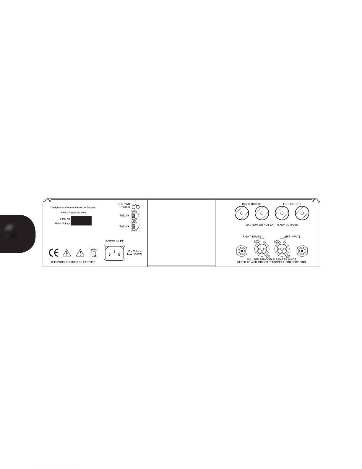
The AC input voltage has been set for the country it was purchased in. Check that the label on the rear panel
matches your AC supply voltage before plugging in. The AC inlet cable provided should be used. If another cable
is used check it is wired correctly. The fuse should be rated at 10 amps.
The wires in the AC input cable supplied are coloured in accordance with the following code:
Green and yellow..............Earth
Blue................................Neutral
Brown.................................Live
The amplier must be earthed. Do not disconnect the AC earth at any time. If in doubt about any aspect of
power supply, consult your Trilogy dealer or a qualied electrician.
A direct connection to a mains outlet is best for your amplier, avoid adapters. To realise your amplier's full
potential we recommend high quality mains conditioning. See www.Isol-8.co.uk for more on power supply and
system solutions from our highly acclaimed sister company.
990/um/20042014
Page 9
9
990/um/20042014
Page 10

10
Connections
It is good practice to complete all interconnections before switching on to avoid any damage to your systems
loudspeakers while plugging in.
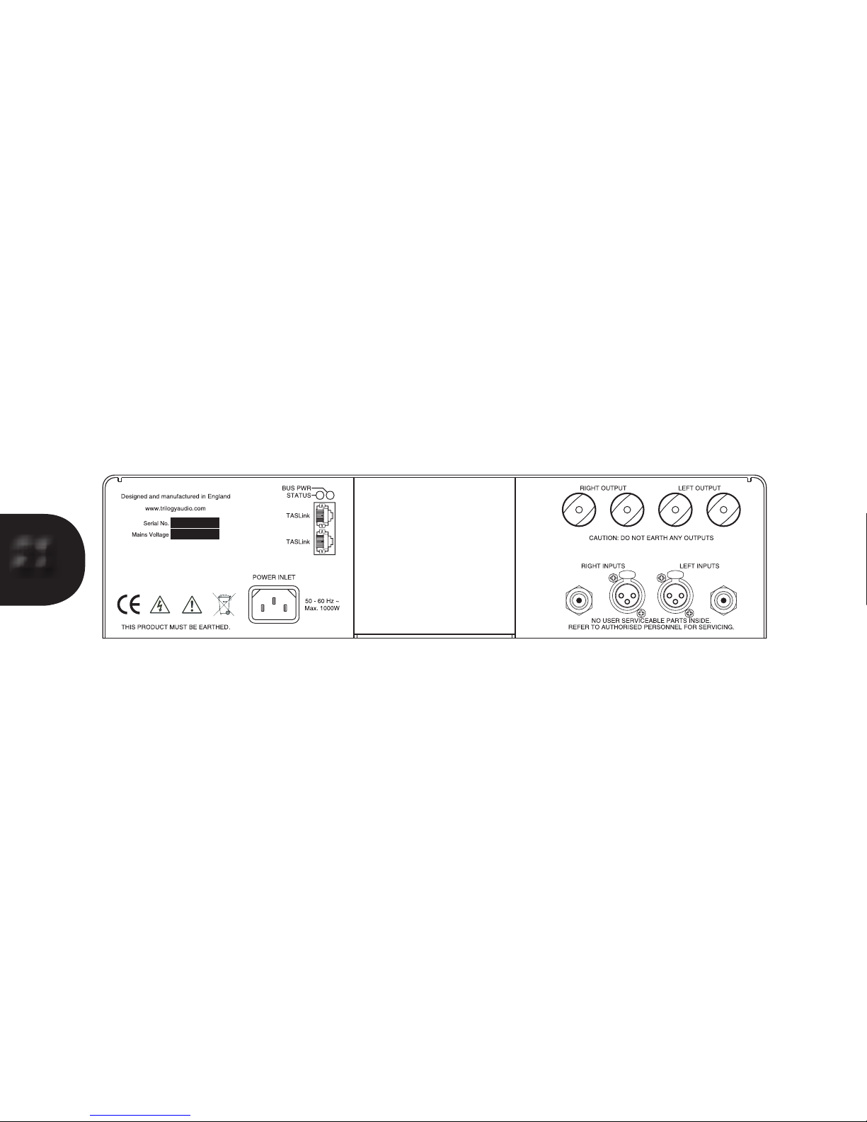
The IEC inlet provides the unit with power. Connect with the supplied AC input cable. It can be left connected at
all times to ensure reliable operation. If not being used for extended periods of time switch off at the mains outlet.
The amplier has two alternative line level audio inputs.
There is a single ended input on RCA “Phono” connectors or balanced input on Neutrik XLR connectors.
Connect your preamplier’s Main output to either of these as required. If your pre amplier offers a choice, it is
better to use the balanced connection.
Each channel has outputs via copper terminals for connection to your loudspeakers. It is important to connect
your speaker cables correctly. Connect the terminal marked + to the positive terminal of your loudspeaker, and
the terminal marked – to the negative. Make sure that each connection is secure and not touching another. Do
not over tighten the terminals as damage may result. Finger tight is sufcient torque.
Twin TASLink connectors allow system interconnection and control via QuietBuss with other Trilogy Audio System
products. This 990 can be remotely switched on and off and safe operation monitored via TASLink. Various other
operational facilities are also available. See your Trilogy Pre amplier manual for further details.
TASLink cables of varying lengths are available from your Trilogy dealer.
990/um/20042014
Page 11
11
990/um/20042014
TRILOGY
Page 12

12
Operation Guide
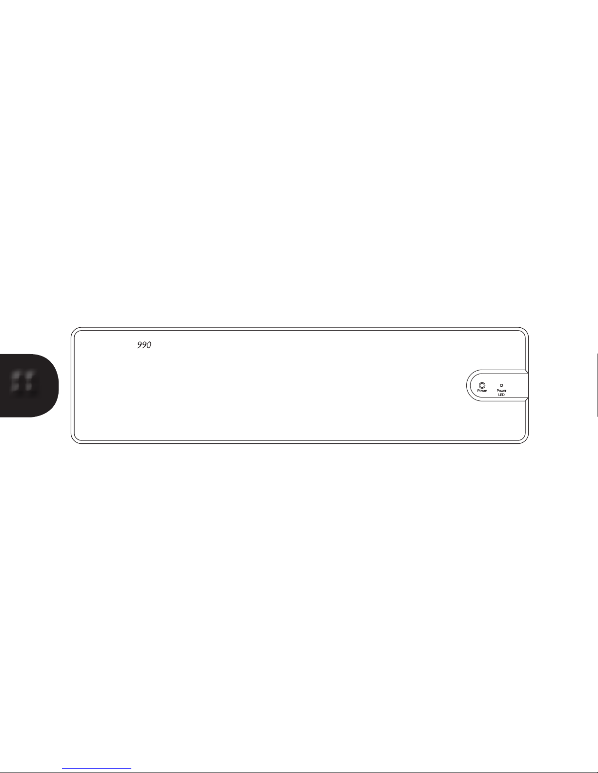
Having made and checked all appropriate input, output and AC connections, the [power indicator] will be dimly
lit. To turn on the 990 briey press the [power button].
The [power indicator] will ash slowly for 25 seconds, then ash more rapidly for a further 25 seconds. During this
“warm up” period, the output will be muted.
The (power indicator) will now remain on. The 990 is now ready for use.
Optimal performance will be achieved in about 1 hour once the amplier has become quite warm to the touch.
To turn the amplier off, press and hold the [power] button for half a second.
990/um/20042014
Page 13

13
990/um/20042014
Page 14

14
Keep Warm Mode
The central uted heatsink is at the very core of the 990’s design. Firstly it forms a very rigid and inert structural
spine. Secondly, it separates the AC mains and power supply from audio electronics. Thirdly, normal nned
heatsinks resonate quite badly and this noticeably effects the performance of the output stage. The 990 does not
suffer from this. Finally, the heatsink is designed deliberately to be of high mass and low efciency. Both of these
work together to maintain the 990’s output stage at the optimal temperature, a temperature that does not vary
much whilst amplifying music. This temperature will vary slightly depending on the temperature of your room but
will typically be 45 degrees Centigrade. This will feel quite warm to the touch and is quite normal.
Once the 990 is on, you may enter “keep warm” mode by briey pressing the [power button].
The [power indicator] and heatsink utes illumination will now slowly and continually cycle between full intensity
to dim.
To bring the 990 back to operation, again briey press the [power button]. The start up sequence will happen in
the usual manner. From this keep warm mode, optimum performance will be achieved in a much shorter period
of time.
If the 990 is connected to a Trilogy Pre-amplier via TASLink, control over the keep warm mode can be made
from the Pre-amplier or the PRC (Personal Remote Control). See your Trilogy Pre amplier manual for further
details.
990/um/20042014
Page 15
15
990/um/20042014
standard
bridge
Page 16

16
Bridge operation
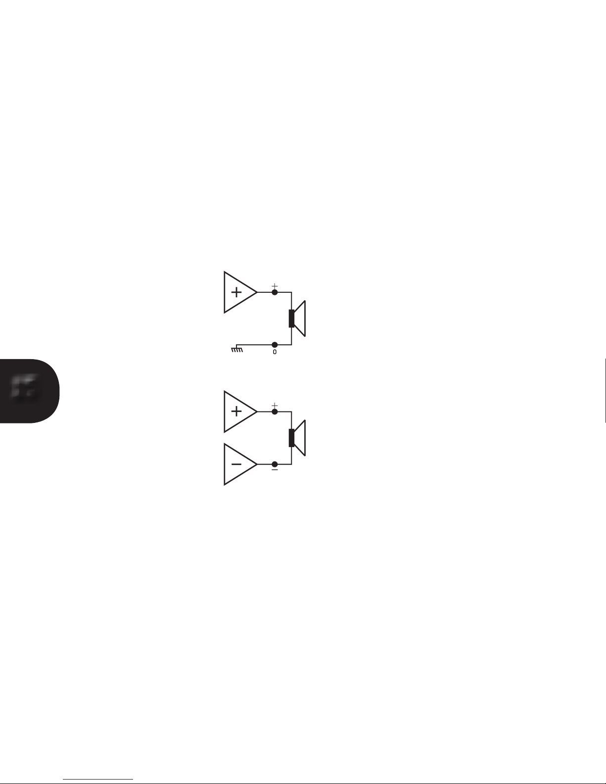
The 990, very unusually, is a true balanced amplier from input, right up to the output stage. In a normal amplier
(even if it has a balanced input), the output to the loudspeaker is connected between the amplier hot (or +)
terminal and system earth.
In a bridge amplier, the loudspeaker is connected between the output of two power ampliers.
Whilst this method is much more costly as four ampliers are required for stereo, the enormous currents that ow
to and from the loudspeaker, do not in any way inuence the very delicate system earth.
DO NOT in any circumstances allow either the + OR the – outputs of the 990 to be connected to earth or each
other. This may be the case with some kinds of loudspeaker switching matrix or some headphone adaptors.
990/um/20042014
Page 17
17
Over Current
DC Offset
Temperature Hot
990/um/20042014
Page 18

18
Operational Warnings
The [Power indicator] is not only used to indicate the operational status of the 990, but also provides a visual
indication of any possible overload or fault condition.
It should be stated that you should not experience any of these conditions in normal use.
Whilst the [Power indicator] is ashing during the warm up period, it is on and off for equal amounts of time.
However, when it is indicating a warning or fault condition, there will be a series of one tenth of a second “blinks”
or “ashes”, which indicate different conditions.
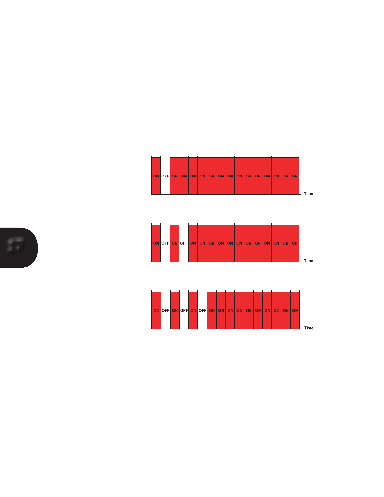
This page details the WARNINGS. These are arranged so that the [Power indicator] is mainly on and “blinks” off.
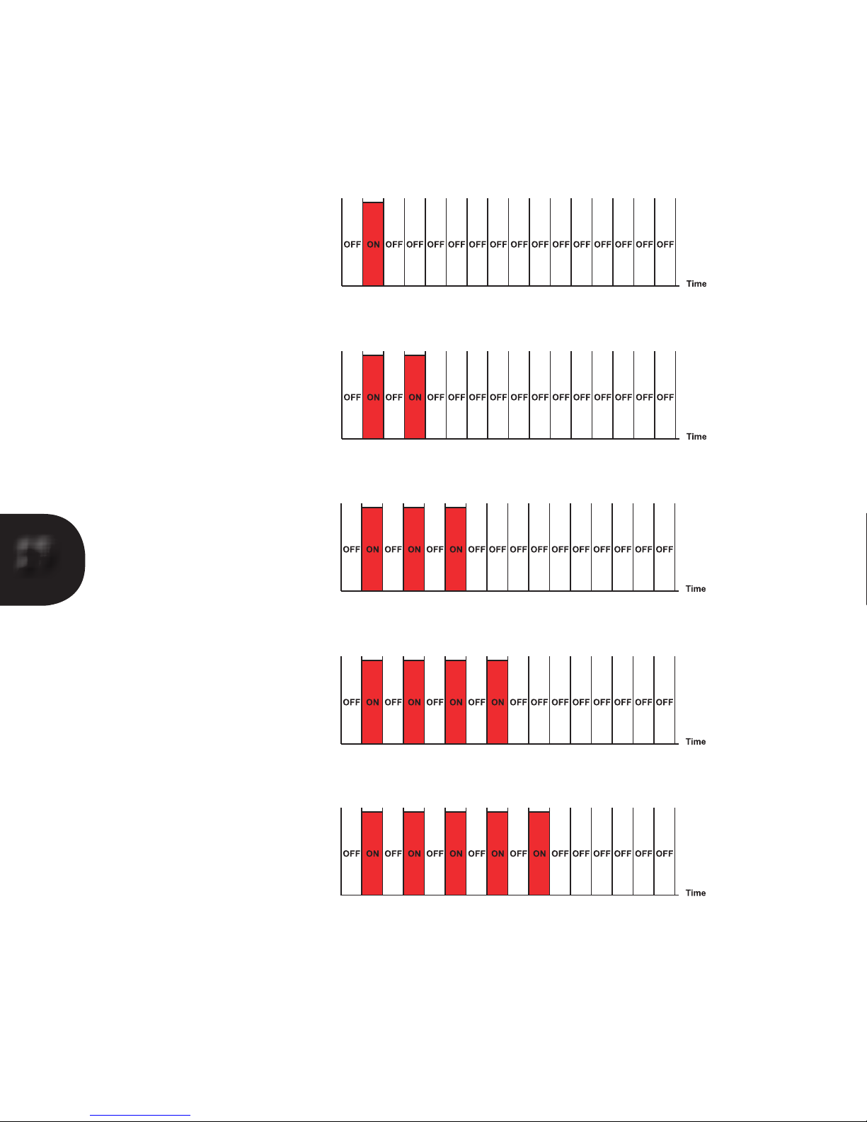
If the [Power indicator] is mainly off and “ashes” on, then the 990 has entered a Lockout mode. This is covered
on the next page.
The three warnings are detailed below:
Over Current
The 990 is being asked to supply too much current to the loudspeaker. The 990 will momentarily mute and
repeatedly continue to do so until the volume is lowered.
The [Power indicator] will “blink” off once in the 1.6 second period. Continued operation in this state will cause
the 990 to enter Over Current Lockout.
DC Offset
The output signal of the 990 has a DC component, or contains very low frequencies at high amplitude. The 990
will mute until this condition has ceased. Generally this condition will be caused by a brown out, or playing source
material with extremely low frequencies at relatively high levels.
The [Power indicator] will “blink” off twice in the 1.6 second period. Continued operation in this state will cause
the 990 to enter DC Offset lockout.
Temperature Hot
If the temperature of the 990’s heatsink reaches 60 degrees centigrade, the following warning will be given, but
the 990 will remain operational.
The [Power indicator] will “blink” off three times in the 1.6 second period and will continue until the 990 cools
below 55 degrees centigrade. If the temperature exceeds 65 degrees centigrade, then the 990 will enter
Over Temperature Lockout.
990/um/20042014
Page 19
19
Over Current Lockout
DC Offset Lockout
Over Temperature Lockout
Power Supply Lockout
Output Stage Lockout
990/um/20042014
Page 20
20
Protective Lockout Modes
As described on the previous page, if the warning condition continues for a period of time, the 990 will enter
Protective Lockout Mode. Once in this mode the 990 will turn off. This will be indicated by the [Power indicator]
being largely off with brief ashes on. Again the number of ashes will indicate the reason for the shutdown.
At this point it is important to record or remember the number of ashes. We call this mode a Lockout, because
you cannot simply turn the 990 back on from the [power button]. We thought this condition too important for a
simple reset. There may, for example, be a problem that needs correcting before re-powering the 990. Examples
are there is a short circuit in the loudspeaker cabling or the airow over the heatsink is obstructed.
If you are condent that you have found the cause of the lockout you can attempt to re-power the 990. You will
need to remove the IEC power inlet cable, wait for 10 seconds and then plug it back in again. Then follow normal
turn on procedure.
If however, the 990 re-enters lockout mode, (remember it may take some considerable time for the fault condition
to re-appear if, for example, it was a temperature lockout) it is important to consult your Trilogy dealer as there
may be an internal fault.
1 ash Over current lockout.
2 ashes DC Offset lockout.
3 ashes Over temperature lockout.
4 ashes Power supply lockout.
5 ashes Output stage lockout.
If the 990 is connected to a Trilogy Pre amplier via TASLink, then these conditions will also be indicated on the
Pre-amplier’s display.
990/um/20042014
Page 21
21
990/um/20042014
Page 22

22
TASLink Overview
TASLink is Trilogy’s proprietary bus system offering power and data to remote displays, and also data to other
Trilogy audio products to synchronise power on/off and provide error information. TASLink has a bus remote line
(GPI) allowing equipment from other manufacturers to be powered on/off by a Trilogy pre-amp, or allow the 990
to be turned on by another system.
Standard Cat5 or Cat5e cables are used, the same as used for computer networks with RJ45 plug terminations.
Do not however cross-plug computer networks and TASLink, as damage may result. It should be noted that
Cat5/RJ45 cables are not unique to computer networks and are often used for telephony and other control
systems. The cross-plugging issue is not unique to Trilogy products and Trilogy can take no responsibility for
damage caused by failure to follow this instruction.
By using standard Cat5 wiring, users can take advantage of any structured wiring in their buildings.
Security Bonding
To protect your investment in Trilogy equipment, this facility allows your 990 to be security bonded to a Trilogy
pre-amp should you have one. Your 990, once bonded, cannot be turned on with its local power button or via
TASLink, other than with the original bonding Trilogy pre-amp.
To achieve this bonding TASLink must be used.
See the relevant section on Bonding in the Trilogy Pre amplier’s user manual.
Please note there is deliberately no indication of which pre-amp is bonded to your 990. This is a security issue.
Rear Panel LEDs
There are two rear panel LEDs and these are used to indicate:
BUS PWR: if TASLink is connected and Bus Power in enabled on the Pre amplier.
STATUS: if the micro controller within the 990 is active.
Diagnostics using these LEDs is possible. You may be asked to look at these LEDs as part of any
telephone support.
990/um/20042014
Page 23

23
990/um/20042014
Page 24
24
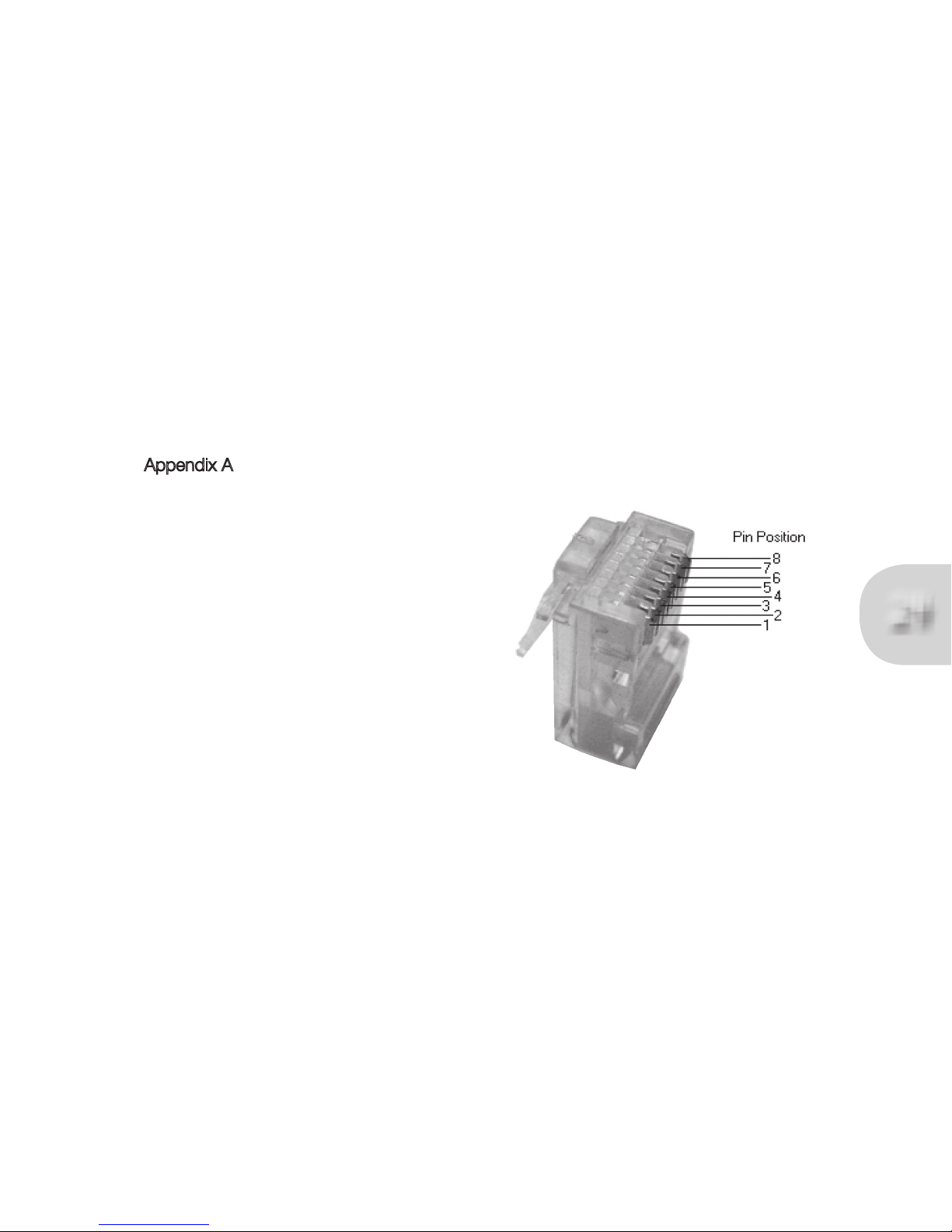
Appendix A
TASLink Pinout
RJ45 FUNCTION
2
1
Orange/white
White/orange
BUS POWER
0V
6
3
Green/white
White/green
LSW
LSS
4
5
Blue/white
White/blue
DATA +
DATA -
8
7
Brown/white
White/brown
BUS REMOTE
LSD
990/um/20042014
Page 25

25
990/um/20042014
Page 26
26
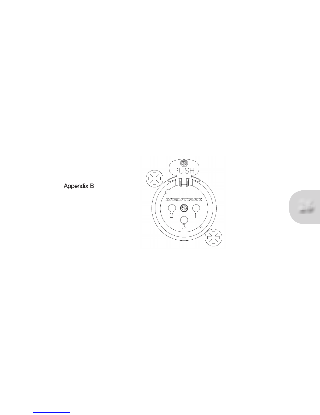
Appendix B
Pin 1 Earth
Pin 2 Hot (+ phase)
Pin 3 Cold (- phase)
990/um/20042014
Page 27

27
990/um/20042014
Page 28

28
Cleaning
Dust the unit regularly with a soft cloth or soft brush. For more stubborn marks make sure the unit is switched off
and disconnected from the power supply. Use a slightly damp cloth with a very small amount of mild detergent
such as washing up liquid. Do not use a wet cloth. Be careful when using cleaning or polishing agents. Never use
abrasives or alcohol based agents, they will harm the surface nish. Do not allow the unit to become wet when
cleaning.
Servicing
Your Trilogy amplier uses thermionic valves or vacuum tubes for amplication. They are the key component in
realising your ampliers very high performance. Valves have a nite lifespan and will need replacing during the
lifetime of the amplier. This lifespan depends on how long and how hard they are used. In typical use, small
signal valves can last for 5000 hours. Frequent switching on and off reduces valve life.
Please bear in mind that some failures can occur early on in a valve’s working life, usually due to mechanical
stresses that can occur during shipping. This is not a reection on the ampliers design but is an inherent
characteristic of all valves, and is impossible to predict even during the ampliers factory burn in period. The
good news is considerate circuit design and modern manufacturing methods mean that valves are now typically
very reliable once established in service.
It is good practice to replace the valves your amplier periodically to prevent sudden loss of a signal path. Your
Trilogy amplier uses readily available and inexpensive valves should replacement be needed. If you are in any
doubt your Trilogy dealer will help you assess whether your valves need replacing.
If your amplier exhibits noticeable loss of performance, extreme sensitivity to vibration or becomes excessively
noisy then new valves should be tted by your authorised Trilogy dealer.
There are no user serviceable parts inside. Do not open or attempt to repair the unit. Refer to your authorised
Trilogy dealer for servicing.
Declarations
This product is guaranteed against defects in material and workmanship for 3 years from the date of purchase.
This Guarantee excludes valves which are guaranteed for 6 months from date of purchase.
The Guarantee is not transferable and is offered to the original purchaser only.
This guarantee does not limit your statutory rights within the country of purchase.
Failure to comply with any of the above instructions during installation or operation will render the manufacturers
warranty null and void.
Marking by the “CE” symbol indicates compliance of this device with the EMC (Electromagnetic Compatibility)
and LVD (Low Voltage Directive) standards of the European Community
This amplier has been tested to ensure that its operation is not adversely affected by normal background levels
of radio frequency interference, and that it does not itself generate excessive amounts of radio frequency energy.
If your amplier exhibits sensitivity to nearby radio frequency devices or is suspected of affecting another device,
increase the distance between them. If the problem persists, consult your Trilogy dealer.
990/um/20042014
Page 29

29
Glossary
Single ended input An input with the signal referenced to earth
Balanced input An input with two signals referenced only to each other.
XLR A professional three pole connector allowing balanced signal operation
Bridge amplier Unusual conguration where the loudspeaker output is not referenced to earth but is
across the output of two balanced ampliers.
Keep warm A facility to keep the 990 in near optimum state but with reduced power consumption.
Bond A unique security feature allowing your 990 to be controlled ONLY by your Trilogy
pre-amplier and be included in it’s the PIN CODE protection.
TASLink Trilogy Audio Systems’ proprietary Link between products.
RJ45 A standard latching connector chosen for TASLink.
Cat5(e) A standard 4 pair data cable chosen for TASLink.
990/um/20042014
Page 30

30
990 Specications
Size 424*428*113 (W*D*H)
Size (including connectors) 424*460*113 (W*D*H)
Size (packaged) 590*610*250 (W*D*H)
Weight 24.5Kg
Weight (packaged) 27Kg
Standby power consumption 4 Watts
Idle power consumption 90 Watts
Max power consumption 1000 Watts
Inputs (single ended) RCA “phono”
Inputs (balanced) XLR 3 Pin female
Input impedance (single ended) 130K Ohms
Input impedance (balanced) 2*130K Ohms
Input sensitivity 1.5V RMS for rated output
Frequency response 10Hz - 30KHZ +/-0.5dB
Rated power (8Ohms) 100 Watts per channel
Rated power (4 Ohms) 200 Watts per channel
Distortion Less than 1% A weighted at rated output
Phase Phase correct (non inverting)
Specication subject to change.
Returns
Should it be necessary for your 990 to be serviced, please send it in the original packaging to your dealer.
If this is not possible please contact us directly and request a Return Authorisation Number. Please mark this
number in the space provided on the outer packaging.
Please do not send products back to us without this number as we will not accept liability for the product.
If a product is not returned to us in its original packaging, after servicing we will return it, in Trilogy packaging
and a nominal charge will be made.
990/um/20042014
Page 31

31
Whilst the information given in this document is correct at the time of printing, small production changes in
the course of our Company’s policy of improvement through continued research and development might not
necessarily be indicated in the specication.
If clarication of any point or specication is required, please refer to your Trilogy dealer.
We welcome your feedback, whether positive or negative, to help us further rene our products.
Please write to; Trilogy Audio Systems
PO Box 56402
London SE3 7WQ
Or fax: +44 (0) 20 8856 0616
Please visit our web site; www.trilogyaudio.com
Acknowledgements
.
Nearly three years in design and development, this current range of Trilogy products are un-paralleled in their
performance, aesthetics and system architecture.
Only when a product is technically near perfect, blended with real passion and soul, is it possible for this level of
overall performance to be achieved.
A great many people have worked tirelessly to help achieve this goal, and I would like to take this opportunity to
thank Emeka Chigbu, Simon Dart, Cliff Orman, Chris Sims and Simon Quill for their dedication to this project.
© Copyright Trilogy Audio Systems 2008. E&OE
990/um/20042014
Page 32

 Loading...