

Page 1

USER MANUAL 925.23102014.V2
USER MANUAL
925
Page 2

2
USER MANUAL 925.23102014.V2
thank you
Welcome
Firstly, thank you for purchasing your Trilogy Audio Systems 925 Integrated amplier, we value your custom.
We strive to design and build world class products that stand the test of time. By reading this manual you can
gain clear understanding of its operation and learn to care for it correctly. In turn, it will reward you with a lifetime
of outstanding performance.
......................................
Nic Poulson.
CEO Trilogy Audio Systems.
www.trilogyaudio.com
Page 3

3
USER MANUAL 925.23102014.V2
Getting Started
5 Introduction
5 About this manual
6 Unpacking
6 Environment
6 Power Supply
8 Connections
10 Security
10 PIN Code Protection
12 Powering the Amplier
14 Overview
14 Absolute Phase
Menu Operation Section
16 Time Settings
16 Sleep To set the sleep timer
18 Timers To set the daily on/off timers
20 Time Set To set the day and time
22 Defaults
22 PIN Codes To enable or disable PIN codes when power applied or for menu
24 Volume To set various default volume parameters
26 Input To assign the default input
26 Film In To assign an input to be the lm input
26 Output To select the default output source
28 Balance To assign the default balance setting
28 Display To set various display parameters
30 Mood Light To enable or disable the blue Mood Lights under the 925
30 Warm Mode To enable or disable Warm Mode
30 External To set TAS link parameters
32 Names
32 Inputs To assign user names to the inputs
34 External To assign user names to peripherals connected by TAS link
36 Tools
36 Int Status To view internal temperature, current, and safety trip counter
38 Bond To bond peripherals to this 908 for security
contents
Page 4

4
USER MANUAL 925.23102014.V2
38 Unbond To unbond peripherals from this 908
38 IR Code To display the codes received by the IR receiver
40 Factory To reset the 908 to factory default settings
TAS link
42 Overview
42 Bus power
42 Bus remote on
42 High speed bus
44 Low speed (quiet) bus
44 Rear Panel LEDs
44 Front Panel Warnings LEDs
Appendices
46 Appendix A TAS link Pinout
48 Appendix B Default settings
Care & Service
50 Cleaning
50 Servicing
50 Declarations
Glossary
51 Glossary
Specications/Returns
52 925 Specications
52 Returns
Acknowledgements
53 Acknowledgements
contents
Page 5

5
USER MANUAL 925.23102014.V2
Introduction
We prefer that your Trilogy dealer delivers, installs, sets up and explains your 925's operation to you.
However, we still recommend that you read through this manual thoroughly and keep it to hand for reference if you intend using some or
all of the 925's complex and rather unique features.
Should any part of this manual or the operation of the 925 not be clear to you, please do not hesitate to contact your Trilogy dealer. If
they are not available please contact ourselves directly.
About this manual
Throughout this user manual, the following icons are used:
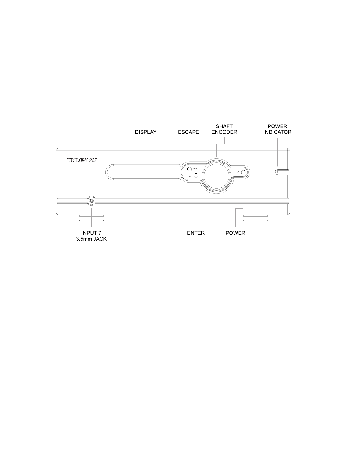
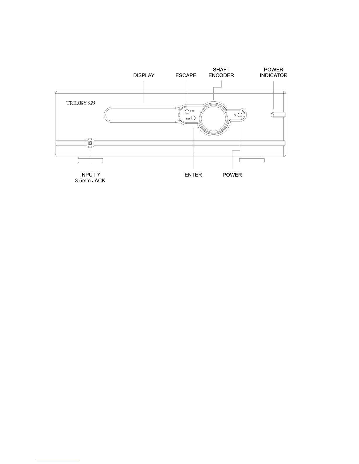
[enter] This refers to a physical control on the 925.
SEND This refers to a physical connection on the 925.
Bal Centre
This indicates information that is presented on
the display.
From this point on, any information presented on the left hand pages are pictorial representations of either the front or back views of the
925 or of the display.
Therefore consider the left hand pages as additional information to accompany the written descriptions on the opposite pages.
Page 6

6
USER MANUAL 925.23102014.V2
Unpacking
Be careful when unpacking your 925, it is heavy. Seek assistance if necessary. Store the packaging safely for future use. It is the ideal
method of protecting your 925 from damage during transport.
Environment
Do not site the 925 near liquids, or place liquid-lled containers near the unit. If liquid does come into contact with the unit there is
serious potential for an electric shock or re hazard. Immediately pull out the mains plug from the wall socket. Contact your dealer to
arrange an inspection before further use.
The 925 is cooled by convection and so needs good circulation of room temperature air, both under and around it. Do not place it near
sources of heat such as radiators or in direct sunlight. Do not enclose in a cupboard. Do not place directly on carpet.
A at, smooth surface is required. As with all high resolution audio equipment, your 925 is sensitive to vibration, strong magnetic elds
and radio interference. A dedicated, high performance equipment platform sited away from other appliances is the optimum location.
Power Supply
The AC input voltage has been set for the country where it was purchased. Check that the label on the rear panel matches your AC
supply voltage before connecting the supply. The AC inlet cable provided should be used.
The 925 must be earthed. Do not disconnect the AC earth at any time. If in doubt about any aspect of power supply, consult your Trilogy
dealer or a qualied electrician.
A direct connection to a mains outlet is normally best for your 925, avoid adapters. To realise your amplier’s full potential we
recommend high quality mains conditioning. See www.Isol-8.co.uk for more on power supply and system solutions from our highly
acclaimed sister company.
Incoming power is fed via a thermal mains breaker on the rear panel. If this trips, it can be reset by pressing the button on the breaker.
However, if the breaker will not reset there is likely a serious internal fault and the unit should be immediately unplugged then returned to
your dealer for servicing.
Page 7
7
USER MANUAL 925.23102014.V2
Page 8

8
USER MANUAL 925.23102014.V2
Connections
It is good practice to complete all interconnections before switching on to avoid any damage to your system’s loudspeakers while
plugging in.
Connect the supplied AC input cable. It can be left connected at all times to ensure reliable operation. If not being used for extended
periods of time; switch off at the mains outlet. See the Menu Operation section for timed, sleep and remote switching.
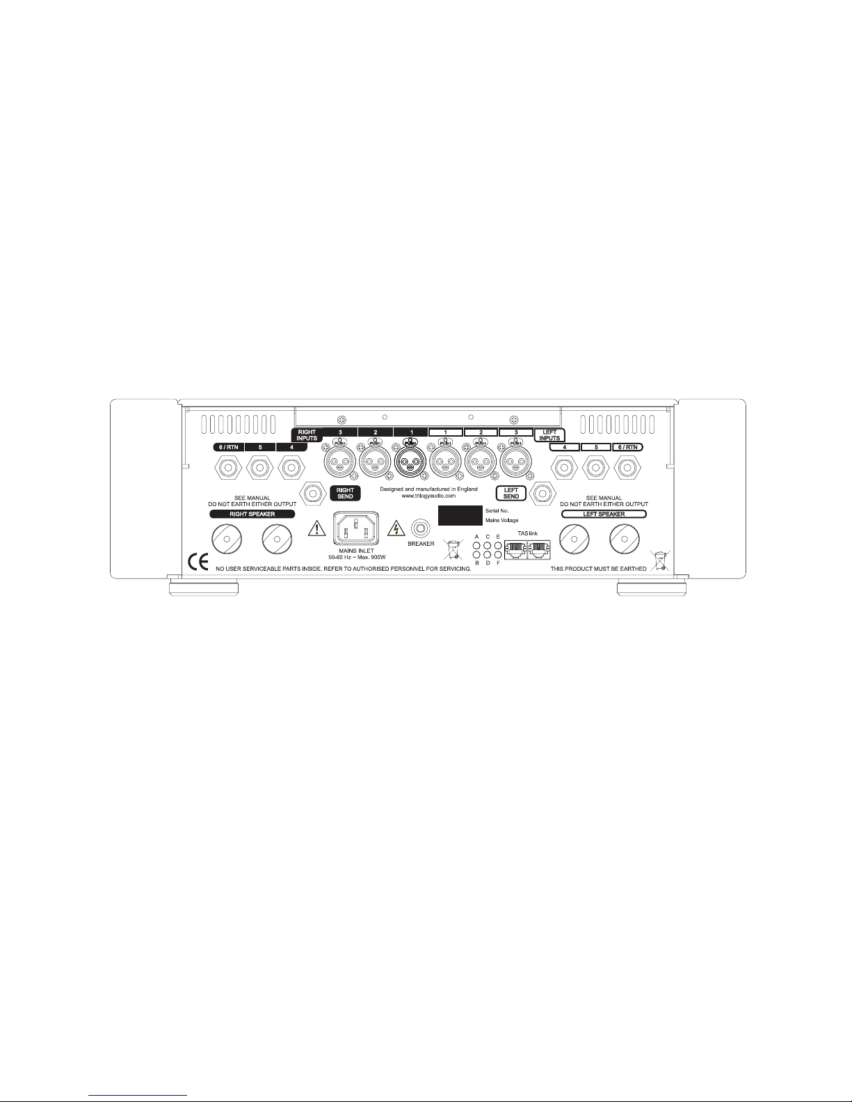
The 925 offers seven stereo, line level audio inputs. There are three XLR balanced (1-3) and three RCA single ended (4-6) inputs on the
rear panel with one input on the front panel (3.5mm stereo 7). Input 6 is associated with auxiliary loops. If a loop function is not required
Input 6 / RTN can be regarded as input 6. Connect your sources to these inputs as required. A separate phono stage will be required for
vinyl playback.
The 925 allows separate selection of the source to be amplied, and the line level source for output SEND to a recorder, AV or multiroom system. Input 6 should be used for any return signal from the recorder etc. To prevent howl round, this 6/RTN cannot be selected
as the SEND output.
Each channel has outputs via copper terminals for connection to your loudspeakers. It is important to connect your speaker cables
correctly. Connect the terminal marked + to the positive terminal of your loudspeaker, and the terminal marked – to the negative. Make
sure that each connection is secure and not touching another. Do not over tighten the terminals as damage may result. Finger tight is
sufcient. Do not attempt to connect one terminal to ground, bridge both channels of the amplier, or connect in any other conguration.
Damage will occur as a result.
Twin TAS link connectors allow interconnection, control and monitoring of other Trilogy products via QuietBus technology. The associated
LEDs on the rear panel give status information. The TAS link section of this manual contains further information. TAS link cables are
available from your Trilogy dealer in various lengths.
Page 9
9
USER MANUAL 925.23102014.V2
Pin Code
[enter]
00----
Rotate [shaft encoder] to display rst Pin Code pair
52----
[enter]
5200--
Rotate [shaft encoder] to display second Pin Code pair
5225--
[enter]
522500
Rotate [shaft encoder] to display third Pin Code pair
522594
[enter]
Warm up...
The number used above is purely an example.
Your unique PIN Code is detailed in the separate sheet accompanying your 925.
Page 10

10
USER MANUAL 925.23102014.V2
Mains Supply
Having checked input, output and AC connections, turn on the mains supply to your 925.
Security
Each 925 comes with its own unique PIN for your security. Please take precautions to remember your PIN and make sure it cannot
fall into the hands of others. Should you not be able to enter the correct PIN, contact your Trilogy dealer.
PIN Code Protection
When the amplier is rst powered, or unplugged for approximately fteen minutes, the amplier requires a security PIN code to be
entered. When the display says PIN Code, press [enter] and the display will read
00----
where 00 are the rst two digits of the
PIN code you are entering. Set these digits correctly with the [shaft encoder], noting you can move backwards through 00 to 99 for
speed. Press [enter], adjust the next pair of digits, [enter] to change the last pair then [enter] again to complete PIN code entry.
If the PIN is entered incorrectly, press [enter] at the warning but note that after three failures, the unit will be locked out for two
minutes before prompting again for PIN entry.
PIN request when power is applied can be disabled in the appropriate menu should you prefer.
Page 11

Page 12

12
USER MANUAL 925.23102014.V2
Powering the Amplier
Once the PIN code has been correctly entered if required/requested, the amplier can be powered using the [power] button. The
message
Warm up...
will be displayed while the circuitry warms up, and any TAS link attached Trilogy products turn on if they
are controlled from the 925. After sixty seconds, the amplier is unmuted, the default input and volume are selected and displayed
before the menu defaults to the home page.
Turn off by again pressing the [power] button, which includes the ability to abort power up during the warming period. The message
Turn Off
is displayed and outputs are muted before valve circuitry is powered down after a couple of seconds.
This simple on/off operation is the standard setting from the Trilogy factory, but the detailed menus offer the ability to select an
intermediate
Keep Warm
mode, where a simple press of the [power] button while powered keeps equipment at near optimum
temperature. This is of particular benet for other Trilogy equipment which can cycle power to its circuitry to keep warm, while
reducing power consumption below standard mute modes. When
Keep Warm
is enabled, full turn off is achieved by pressing and
holding the [power] button.
Page 13
13
USER MANUAL 925.23102014.V2
Listen source options
Input 1
Input 2
Input 3
Input 4
Input 5
Input 6
Input 7
Send output options
Input 1
Input 2
Input 3
Input 4
Input 5
Balance options
Mute Right
Bal <15 .... Bal <1
Bal Centre
Bal >1 .... Bal >15
Mute Left
Brightness options
Bright Auto
Bright 1 .... Bright 9
More options
More
Time
Defaults
Names
Tools
Page 14

14
USER MANUAL 925.23102014.V2
Overview
The Trilogy 925 offers a nested menu structure to access the variety of options. This is intuitive, using a combination of [enter] /
[escape] buttons and the rotary [shaft encoder].
By default, the amplier displays what we call the ‘Home Page’, which is selectable as a blank screen, Trilogy logo, time, input or
volume. The home page can be set differently when the amplier is off, compared with when it is powered.
Navigation of the menu uses the [escape] and [enter] buttons together with the rotary [shaft encoder]. Because the [shaft encoder]
is normally used to adjust the volume from the home page, the rst step to access any control is to press [enter] once, which
shows the input selected for listening. This listen source can then be changed with the [shaft encoder] and allows the most basic of
operations.
At this point you can press escape or enter once more. Pressing escape will return to the home page and the shaft encoder will
control volume. Pressing enter will allow selection of the source that is sent to an external recorder or processor. [enter] again to
adjust balance. [enter] again for display brightness and choose from automatic according to ambient light, or xed levels 1-9. The
next [enter] will display
More
, which is the route into the detailed menus, which are accessed by turning the [shaft encoder].
The top level menu is circular, so pressing [enter] when
Moreis
displayed will return to listen source selection. [escape] at any time
from these top level settings to return to the home page, and press [escape] from the home page to display the current time. Holding
[escape] for several seconds at the home page will display the unit’s serial number when the amplier is powered off. Similarly
holding [escape] when the amplier is on will allow absolute phase selection.
Absolute Phase
Before considering detailed menus below, absolute phase should be explained. Unlike reversed wiring that places left and right audio
out of phase and affects the stereo image, absolute phase reversal changes both left and right channels together. Replay of recorded
material will then move the speaker backwards rather than forwards for an initial compression of air in the original recording. High
end systems can reveal such errors which may be the recording itself rather than reproduction, and may vary even within a single
album. When [escape] is held at the home page to enable absolute phase changes, the display shows the existing phase setting
positive or negative. Pressing [escape] again will toggle between phase settings. To leave this mode, hold [escape]. The IR remote
also offers absolute phase change, using the Menu- and Menu+ on the home page to select negative and positive phase directly.
Using either front panel or IR control, changes to absolute phase are shown with a leading arrow to make it clear there has been a
change.
Page 15

15
USER MANUAL 925.23102014.V2
More
Time
Sleep
Timers
Time Set
More
Time
Sleep
Sleep Off
Sleep 0:01 .... Sleep 2:00
Page 16

16
USER MANUAL 925.23102014.V2
Menu Operation
You will nd it intuitive, but it is unusual that you advance between top level menus of input, output, balance, brightness and more using
the [enter] button, whereas in the detailed menus found within More, the different menus are selected with the [shaft encoder]. The logic
for this is we nd it acceptable to select between the small number of high level menus using [enter], and also that each of these top
level menus demands the use of the [shaft encoder].
To access the detailed menus,
More
should be displayed then turn the [shaft encoder] to select between time, defaults, names and
tools. If you have enabled menu lock in the defaults (disabled by default), on turning the [shaft encoder] you will be prompted to enter the
four digit menu PIN code provided with your 925. This is a different number to the six digit PIN entered when power is applied.
More / Time
This includes setting the current time and sleep time similar to that found on an alarm clock, putting the amplier to sleep after an
adjustable number of minutes. On and off timers are also provided for each day of the week, plus global on/off timers that apply every
day. Individual timers can be disabled and only some timers used if required. For example, turn on Saturday morning and turn off Sunday
evening. Press [enter] to access
Sleep
, then select other time options if required.
More / Time / Sleep
Pressing the [enter] button when
Sleep
is displayed, will allow the user to set a sleep timer to turn the amplier off automatically after a
set time. However during this countdown period the front panel button, an external remote or one of the timers might switch the amplier
off rst.
The default value displayed is
Off
, but using the [shaft encoder], the time can be adjusted from
0:01
(one minute until sleep) to
2:00
(two hours until sleep) in one minute steps. Once set as required, [escape] from this menu or leave the display timeout to return to the
homepage if enabled. When the unit goes to sleep, by default it will switch off both the amplier and any TAS link attached peripherals.
If display timeout is not enabled and you stay on the sleep display, you will see a live countdown. If you wish to disable the sleep timer,
set it to
Off
.
Page 17

17
USER MANUAL 925.23102014.V2
More
Time
Timers
Mon ><:00
Mon ><:00
Tue ><:00
Tue ><:00
Wed ><:00
Wed ><:00
Thu ><:00
Thu ><:00
Fri ><:00
Fri ><:00
Sat ><:00
Sat ><:00
Sun ><:00
Sun ><:00
All ><:00
All ><:00
Page 18

18
USER MANUAL 925.23102014.V2
More / Time / Timers
Timers are provided to allow automatic on/off switching customised to your daily routine, like a modern central heating controller. This
facility may be used to bring your audio equipment to optimum temperature before listening, to minimise power wasted overnight in
maintaining temperature, or to provide wake-up music like an alarm clock.
[enter] from Timers to show the ‘on timer’ for Monday, designated with the lled square top right of the display. The day will be ashing.
Turning the [shaft encoder] to the right shows the off timer for Monday with an empty square bottom right, then on/off for every day with
the addition of ‘all on’ and ‘all off’ timers which will work every day.
The timer hours are adjustable
00
to 23, minutes are 00 to 59 as expected. We deliberately prevented the [shaft encoder] ‘wrapping
round’, eg 23 hours to 00 hours. Before 00 hours, there is an additional setting of
><
hours which disables that timer. Trilogy 925
ampliers are shipped with all timers disabled and minutes set to 00, that is
><:00
.
To adjust a timer, select the timer of interest with the [shaft encoder] and press [enter]. This allows hours to be changed, including
disabling with a setting of
><
. Press [enter] to edit the minutes or [escape] back to selecting the different days on/off. It will be clear what
you are changing with the [shaft encoder] as the display will be ashing.
We have included what we hope is a useful feature. After editing timer minutes, pressing [enter] moves to the next timer —press [enter]
to edit that. This speeds setting as you are likely to edit an off timer when you have edited that day’s on timer. However if you edit the
minutes on one timer and do not want to edit the next timer, simply press [enter] then choose another timer, or [escape] again to leave
the timer menu.
The timers were designed with exibility in mind. Day timers do not have to be used in on/off pairs, so you could have your system
switch on Saturday morning and keep warm until Sunday evening, just using Saturday on and Sunday off timers. Similarly, each day
could turn on at different times, but the All off timer would switch off the system at the same time every day.
When the unit switches off, it will switch off both the amplier and any TAS link attached peripherals.
Page 19

19
USER MANUAL 925.23102014.V2
More
Time
Time Set
Day HH:MM
Page 20

20
USER MANUAL 925.23102014.V2
More / Time / Time Set
An internal clock allows the amplier to operate its on/off timers and display the current time if required. The clock must be set by the
user but, once the time is set, it keeps time even when there is no mains power applied. This clock offers the same accuracy as typical
quartz units that are not locked to a time reference such as the internet or a radio signal. As for similar devices, the clock may need
adjusting occasionally.
To adjust the clock, press [enter] at the
Time Set menu
. The day and time will be displayed with the day ashing. Use the [shaft
encoder] to adjust the day, [enter] to make the hours ash and adjust (always 24 hour clock), then [enter] again to adjust minutes. [enter]
will cycle back to adjusting the day. Although seconds are not displayed, internally they are reset to zero if the time is adjusted.
Page 21

21
USER MANUAL 925.23102014.V2
More
Defaults
PIN Codes
Volume
Input
Film in
Output
Balance
Display
Mood Light
Warm Mode
External
More
Defaults
PIN Codes
Power Up
Use PIN
Skip PIN
More
Defaults
PIN Codes
Menu
Use PIN
Skip PIN
Page 22
22
USER MANUAL 925.23102014.V2
More / Defaults
A wide range of default values can be set in this menu, including startup listen and send selections, startup volume and settings to integrate a surround system. Display parameters such as home page, timeout and brightness, language, and whether volume is displayed in
decibels or 0..99. Settings for external equipment using TAS link communications, and new facilities as they are developed.
More / Defaults / Menu Lock
PIN codes has two sub-menus to separately enable PIN requests when the amplier is powered or to enter all of the detailed menus
beyond More. Whether a PIN is requested in each case can be set here, pressing [enter] at
Power Up
or
Menu
allows
Use PIN
or
Skip
PIN
to be selected with the [shaft encoder].
Page 23

23
USER MANUAL 925.23102014.V2
More
Defaults
Volume Trim
Input X
Trim -10 .... Trim +10
More
Defaults
Volume
Start
Mute
-63.0dB .... -0.0dB
More
Defaults
Volume
Max
Mute
-63.0dB .... -0.0dB
More
Defaults
Volume
Film
Mute
-63.0dB .... -0.0dB
Page 24

24
USER MANUAL 925.23102014.V2
More / Defaults / Volume
If you press [enter] when you get to the defaults volume menu, you will see
Trim
. Rotate the [shaft encoder] to see alternatives
Start,
Max
and
Film
. In order these are,
Trim
Volume offset for the selected input, to equalise levels between sources. Each step is 1dB.
Start
Default volume level every time the pre-amp is turned on, unless the default input is set to be a lm input, for example from a surround
processor.
Max
Maximum volume level that can be achieved for all inputs except any designated lm input. This is useful when you don’t trust others
with your speakers! It is possible to increase the effective volume beyond this setting by adjusting the input trim. If the maximum setting
is reduced below the startup setting, when [escape] is pressed the startup level is automatically lowered to match.
Film
Nominally unity gain for surround systems where an input has a xed volume level and all adjustments are made on the surround
processor. The audio performance of the Trilogy 908 pre-amp benets from the lack of closed loop control of the pre-amp gain, hence
the gain will vary depending on the valves. This setting allows ne tuning of the unity gain, or adjustment to a value which is not unity.
With
Trim, Start, Max
or
Film
displayed, press [enter] to view and change the setting with the [shaft encoder]. Note that when you
press [enter] to adjust all but trim, the pre-amp volume will change to the setting which you want to edit, so you can audition the level
correctly. For
Max
in particular we recommend caution. Press [escape] to leave the menu and the new value is saved.
You will not be able to edit the
Film
setting unless you have a lm input dened (see more/defaults/lm in) and that input is selected. If
you have a lm input selected, you will not be able to edit
Start
or
Max
which do not apply to the lm mode.
Factory defaults for these volume settings are
Trim
0 all inputs
Start
-60dB (12 when display is set to use 0..99, not dB)
Max
-12dB (99)
Film
-12dB (81)
Page 25

25
USER MANUAL 925.23102014.V2
More
Defaults
Input
Input 1
Input 2
Input 3
Input 4
Input 5
Input 6
Input 7
More
Defaults
Film In
Nofilm
Input 1
Input 2
Input 3
Input 4
Input 5
Input 6
Input 7
More
Defaults
Output
No output
Input 1
Input 2
Input 3
Input 4
Input 5
Page 26

26
USER MANUAL 925.23102014.V2
More / Defaults / Input
With Input showing, press [enter] to see the input that is selected every time the amplier is turned on with the [power] button, timers
or externally via TAS link. Options are the seven inputs. The default startup volume will also be selected at power on unless that input
is designated as the lm input, typically connected to a surround sound processor. In that case the default lm volume is used. Hence
menus associated with default input are defaults / volume and defaults / lm in. Factory default is input 1 selected at power on. Changes
to this setting will only be evident next time the amplier is turned on.
More / Defaults / Film in
If an input is designated here as the ‘lm input’, it has its own setting for volume which over-rides the volume control and the volume
is automatically changed to that setting when the lm input is selected. This level is set in defaults / volume / lm. When listening to a
‘normal’ stereo input after the lm input, volume is restored to the default startup volume set in defaults / volume / start.
No Film is the factory setting for this parameter. To change this, press [enter] when Film in is displayed, then use the [shaft encoder]
to select the lm input. To avoid the volume jumping between the stereo and lm volume settings as you pass over the currently selected
input, changing this setting has no direct effect. Once an input is assigned as the lm input, it must be deselected if already selected,
then selected to enter the lm mode.
More / Defaults / Output
The default output is selected when power is applied to the 925. The amplier does not have to be turned on. This operation is quite
deliberate. Whether the amplier is on or off, it was felt important to maintain the currently selected record source so a recording can
continue. The record output is maintained in all standby or off modes, dependant only on mains power being available. This setting
differs from the default input which is selected every time the amplier is turned on — the default output is only selected when mains is
connected. Although applied at different times to the default input, changes are made in the same way, with options of
No output
or
any input 1-5.
Page 27

27
USER MANUAL 925.23102014.V2
More
Defaults
Balance
Bal <15 .... Bal <1
Bal Centre
Bal >1 .... Bal >15
More
Defaults
Display
Home On
Blank
Logo
Time
Volume
Input
Home off
Blank
Logo
Time
Timeout
Off
30 secs
60 secs
90 secs
Bright
Bright Auto
Bright 1....Bright 9
Page 28

28
USER MANUAL 925.23102014.V2
More / Defaults / Balance
Default balance is similar to default startup volume as it is applied every time the amplier is turned on. Default balance is not used in
lm mode and can only be auditioned if the selected input is not designated as the lm input. Similar to adjusting default volumes, when
default balance is adjusted the amplier follows changes for proper auditioning.
Factory default balance is
Bal Centre
which will be displayed when you press [enter] from
Balance
. Adjust balance using the [shaft
encoder] from the greatest left bias
<15
to a right bias of
>15
. The default balance cannot be adjusted to fully mute left or right speakers,
a feature which is only available on the ‘live’ balance control to check for faults. For those interested in dB, each step is 1.0dB where the
volume adjustment permits —if the volume is near minimum or maximum levels, the balance control will be limited in the range it can
achieve.
Although volume can be displayed in dB or 0..99, balance is displayed as a number only.
More / Defaults / Display
Press [enter] then use the [shaft encoder] to see the display options
Home On
What the display shows at idle when the pre-amp is on, e.g. time or input
Home Off
What is displayed when the amp is off
Timeout
After using a menu this dictates the time taken to return to the home display
Bright
Display brightness can be changed ‘live’, but this is the startup setting
dB or 0..99
Volume can be displayed in decibels (dB) or as a range 0..99
Language
The amplier hardware permits foreign language support in the future
With any of the above displayed, press [enter] to see the current setting and make changes.
The options for
Home On
are a blank screen, the Trilogy logo, time of day, volume or input name. It is not logical for the 925 to display
volume or input when it is switched off, so
Home Off
does not offer these options. Factory settings for these home pages are blank
when the Amplier is off and volume when turned on. Note that the blank display shows a single dot to the left when the Amplier is off
to indicate the unit is powered, as the main power LED is not illuminated.
Timeout
can be set to off (disabled), 30, 60 or 90 seconds. This is the time to return to the home display from menus. Default Bright can
be
Bright Auto
, depending on ambient light, or a xed setting of
Bright 1
(dim) to
Bright 9
.
Page 29

29
USER MANUAL 925.23102014.V2
More
Defaults
Display
dB or 0..99Vol dB
Vol 0..99
Language
English 01
Not fitted
More
Defaults
Mood Light
Off
On
More
Defaults
Warm Mode
Warm off
Warm on
More
Defaults
External
Bus power
Pwr on
Pwr off
Bus remote
Not used
In on
In warm
Out on
Out warm
High speed
Hi off
Hi on
Page 30

30
USER MANUAL 925.23102014.V2
When the
dB or 0..99
volume option is set to decibels, maximum volume is 0.0dB. Lower volumes are shown as a negative value,
e.g. -10.0dB is 10dB below the maximum possible level. This mode will suit those with a technical interest, but might be confusing as
the displayed number gets larger as the volume is lowered. The alternative is 0 to 99 where 99 is the maximum level.
The 925 has been designed to accept foreign language support in the future. Press [enter] to access this setting, and use the [shaft
encoder] to select the
Language
. Note:
Language
will only allow English at this time.
More / Defaults / Mood Light
Mood lighting offers blue LEDs that illuminate the area underneath the amplier's front panel. This feature is common to some Trilogy
products and can be selected as permanently off or on when the amplier is powered.
More / Defaults / Warm Mode
By default, warm mode is off. When enabled, a short press of the power button turns the 925 on, a short-press when on puts it into
warm mode, a long press when on or warm will turn the equipment off. For the 925 alone, warm mode simply mutes the amplier and is
not of great benet. This facility is really intended for use with our other ampliers that have a true ‘keep warm’ mode. When connected
via TAS link, placing the 925 in warm mode will maintain a lower, standby temperature on those other ampliers which keeps them ready
for use.
More / Defaults / External
This menu allows changes to TAS link settings for bus power, bus remote GPI and high speed data. We suggest you read the TAS link
overview before changing these settings.
Bus power
Bus power can be turned on or off. It is on by default. The bus must be powered by the amplier or another Trilogy
power source for the low speed bus to operate
Bus remote
The bus remote line is one pin of the TAS link connector and is used to turn on Trilogy, or other manufacturer’s,
equipment that is not equipped with the TAS link low speed bus. Alternatively, the bus remote line can be an input to
the 925 amplier to allow turn-on from other systems. Options are,
Not used
Factory default
In on
Input with <2.5V turn off and >7.5V turn on
In warm
Input as above with additional 2.5V-7.5V keep warm
Out on
Output nominal 10V when pre-amp is on
Out warm
Output nominal 10V when pre-amp is on or warm
Requires defaults/warm mode to be enabled
High speed
By default the high speed data is off. This is used for external displays and multi-room
control systems.
Page 31

31
USER MANUAL 925.23102014.V2
More
Names
Inputs
External
More
Names
Inputs
1Input 1
Input 1
2Input 2
Input 2
3Input 3
Input 3
4Input 4
Input 4
5Input 5
Input 5
6Input 6
Input 6
7Input 7
Input 7
Page 32

32
USER MANUAL 925.23102014.V2
More / Names
Inputs are named here. Where Trilogy peripherals are installed on TAS link and can be named, this is also done in these menus. [enter] for
Inputs
, to name the seven inputs. The option to give names to TAS link devices relies on suitable devices being connected.
More / Names / Inputs
The amplier leaves the factory with input names set to Input 1, Input 2 etc. These names can be edited, for example to show the
equipment type such as CD or Tuner. Names are limited to ten characters, but it is possible that not all characters will t on the display.
We use variable width fonts on the display to improve the look, meaning a capital “B” is much wider than a lower case “i”. Using variable
width fonts actually increases the number of characters available on the display but it does mean the characters available depends on
what you want to display.
With Inputs showing, press [enter] and the display will show the input number and name of the rst input,
1Input 1
, where the rst
character will be ashing. At this stage you can select which input name to edit with the [shaft encoder]. When the desired input is
displayed, press [enter] again and the rst number will disappear to show the input name as it will appear in normal operation,
Input 1
.
Again the rst character is ashing, but now it is ashing on the rst character of the name which can be edited using the [shaft
encoder]. Pressing [enter] moves to the second character, and so on through all ten possible characters before returning to the rst
character. Each ashing character can be changed with the[shaft encoder]. There is no delete function, so simply set that character to a
space which is found by turning the [shaft encoder] fully anticlockwise. Because it would be impossible to see a ashing, blank space, if
you are editing a character that is a space, a dot ashes at the top of that position.
Ten characters are allowed, even if they do not all t onto the display. If you change characters near the beginning of the name, you may
nd end characters come into view, but if they are out of view during editing they will not be seen during normal operation. We could
have scrolled the display for you to edit end characters otherwise off the display, but our method means you will not waste time editing a
long name only to nd it does not t in normal use!
Pressing [enter] to cycle through the characters applies even when the characters are off the end of the display. You may need to press
[enter] a few times without seeing a ashing character before returning to the rst character ashing.
Page 33

33
USER MANUAL 925.23102014.V2
More
Names
External
01. .... 24.
Page 34

34
USER MANUAL 925.23102014.V2
More / Names / External
Shipped from the factory, other Trilogy equipment will turn on and off, following the 925 amplier if connected over TAS link. There is no
need to name devices that are controlled over the TAS link low speed bus, but naming allows their status to be checked through the
display of the 925. This status includes running temperature and fault messages. Naming devices also allows their serial number to be
checked remotely.
To allow TAS link communication, each device controlled via low speed bus needs a unique ID number. From the factory no ID number is
set on equipment that does not have the facility to act as a controller, such as a power amp.
This menu intelligently combines the assignment of ID numbers and the naming process.
When rst run with new equipment, pressing [enter] on this menu will display
01.
where 01 is the ID number and the dot means no device has responded. Use the [shaft encoder] to select ID 02, 03 etc. to a maximum
of 24.
We suggest you use contiguous ID numbers starting from 01, as unit 01 is the rst status that is fetched in that menu. With 01 (or other)
displayed, low speed bus units should have their front panel LEDS mostly off with a short ash on. This indicates the unit's button is
temporarily not used for on/off and can be used to ‘grab’ an ID number from the 925. If you need to switch off the remote devices during
this time, for example due to excessive audio levels, use the 925 power button to switch off both the 925 amplier and connected
devices.
A two second press of the power button of a remote device will cause that device’s LED to change from an occasional ash to rapid
ashing, to indicate it has taken the current ID. With multiple devices, it is possible to move between ID numbers 01,02 etc. using the
[shaft encoder] and device LEDs will change their ashing to indicate which is being addressed. Grabbing an ID number where that ID
number is used elsewhere, will cause the original device to automatically reset to having no ID number, just as it leaves the factory.
Once a device has an ID number, it will return with the factory name e.g. 01913 and names can be edited in the same way as input
naming. Press [enter] and 913 will be displayed with the rst character ashing. Edit the name, using [enter] to advance through the
characters and [escape] to save. There will be a short delay showing 01.again while the name is written and read back over the TAS link
low speed bus.
Page 35

35
USER MANUAL 925.23102014.V2
More
Tools
Int status
Ext status
Bus status
Version
Bond
Unbond
IR Code
Factory
More
Tools
Int status
Graphs
More
Tools
Int status
Info
More
Tools
Int status
Trip Count
More
Tools
Ext status
01.
....
24.
More
Tools
Bus status
Pwr
9.8V
Pwr
0.00A
Rem
0.0V
Rem
0.00A
More
Tools
Version
Internal
Master
Vx.xx
Internal
Display
Disp x.xx
Internal
Power
Vx.xx
External
01. .... 24.
Page 36

36
USER MANUAL 925.23102014.V2
More / Tools
Tools offers detailed system information —925 internal status, TAS link peripheral status, a ‘health check’ for the TAS link bus itself, and a
check of software versions in the amplier and peripherals. Tools also allows infra red remote checks, presets to be returned to the factory default and TAS link equipped peripherals to be ‘security bonded’ to the preamp.
More / Tools / Int status
The Trilogy PRC remote has a dedicated status button which accesses this point in the menu directly. To view internal status options follow the PRC status button with enter, or to view external status follow PRC status with Menu+ before enter.
Three internal status menus are provided with graphs, info and a so-called trip counter. These provide data related to the sophisticated
monitoring system that is used to maintain safe operation at all times.
Temperatures and critical voltages report to a dedicated microcontroller. An intensive R&D project produced specially formulated
algorithms to monitor output current and voltage against time and frequency with great accuracy. This enables reliable discrimination
between DC faults or demanding musical conditions, providing excellent protection but avoiding unwanted shutdowns.
The graph shows bar graph measurements of each channel's output current, the top two rows of the dot matrix are the left channel
and the bottom two rows are the right channel. For each channel the two rows are used for the two bridged power ampliers used by
each 925 channel. Normal listening volume should see these two current bargraphs reach no further than the right side of the display
only momentarily. Once excursions beyond this normal listening level threaten to overload the amplier then the central three dots of the
display show a horizontal overload meter. Should this in turn reach the right side of the display then the output will be muted for enough
time to allow the amplier to recover. This time varies from less than a second to many tens of seconds and is based on the algorithms
mentioned above.
Page 37

37
USER MANUAL 925.23102014.V2
More
Tools
Bond
More
Tools
Unbond
More
Tools
IR Code
IR 0000
Page 38

38
USER MANUAL 925.23102014.V2
More / Tools / Bond
To protect your investment in Trilogy equipment, this facility allows many Trilogy peripherals to be security bonded to the 925 amplier.
The connected equipment, once bonded, cannot be turned on with its local power button or via TAS link other than with the original
bonding 925. With target peripherals connected to TAS link, press [enter] and the message Done will be displayed. To prove bonding has
been successful, power off bonded equipment either with their front panel buttons or via the 925. Then attempt to power peripherals
with their front panel buttons which should not work if bonding has been successful.
Please note there is deliberately no indication which equipment is bonded to which. This is for your security.
More / Tools / Unbond
When reconguring your system, or moving to a different location, there may be a need for bonded equipment to be unbonded. Even
Trilogy dealers are unable to undo security bonding and only the original 925 can unbond those items which it has previously secured.
After pressing [enter] and receiving the message ‘Done’, front panel buttons should be used, like bonding above, to test whether
equipment can be turned on locally. In this case, it should now be possible to power peripheral equipment via their local front panel
buttons.
More / Tools / IR Code
The 925 is supplied with the full function, solid aluminium PRC remote control. It is also possible to use programmable remotes to
operate the 925. Although some programmable remotes are very capable, experience shows that some can be complicated to setup.
The standard factory setting for the 925 amplier is Philips’ RC5 remote control standard with a system code of 16 decimal. The
command codes in decimal below may be useful to program a remote control.
01....06
Input 1 … Input 6
15
External status
80
Escape
81
Enter
12
Power
13
Mute
16
Volume up
17
Volume down
86
Menu up
85
Menu down
47
Time
To aid fault nding with any remote control, the IR Code page shows the received two digit system code and two digit command as
decimal numbers for any RC5 IR code received. The toggle bit that shows separate key remote presses is indicated with a T sufx.
When nothing is received the display shows IR ----. If the display continues to show this despite you sending Infra Red commands, then
those commands are not Philips RC5.
Page 39

39
USER MANUAL 925.23102014.V2
More
Tools
Factory
Restore?
Page 40

40
USER MANUAL 925.23102014.V2
To leave the IR code display, you must use the front panel [escape] button, or wait for timeout. You cannot escape with infra red escape.
More / Tools / Factory
Selecting
Factory
, will prompt you with
Restore?
to check whether you are really sure you want to reset.
If you press [enter], this will return all values to standard, detailed in Appendix B. To abort, press [escape].
Page 41

Page 42

42
USER MANUAL 925.23102014.V2
TAS link Overview
TAS link is Trilogy’s proprietary bus system offering power and data to remote displays, and also data to other Trilogy audio products
to synchronise power on/off and provide error information. TAS link has a bus remote line (GPI) allowing equipment from other
manufacturers to be powered on/off by the 925, or allow the 925 to be turned on by another system.
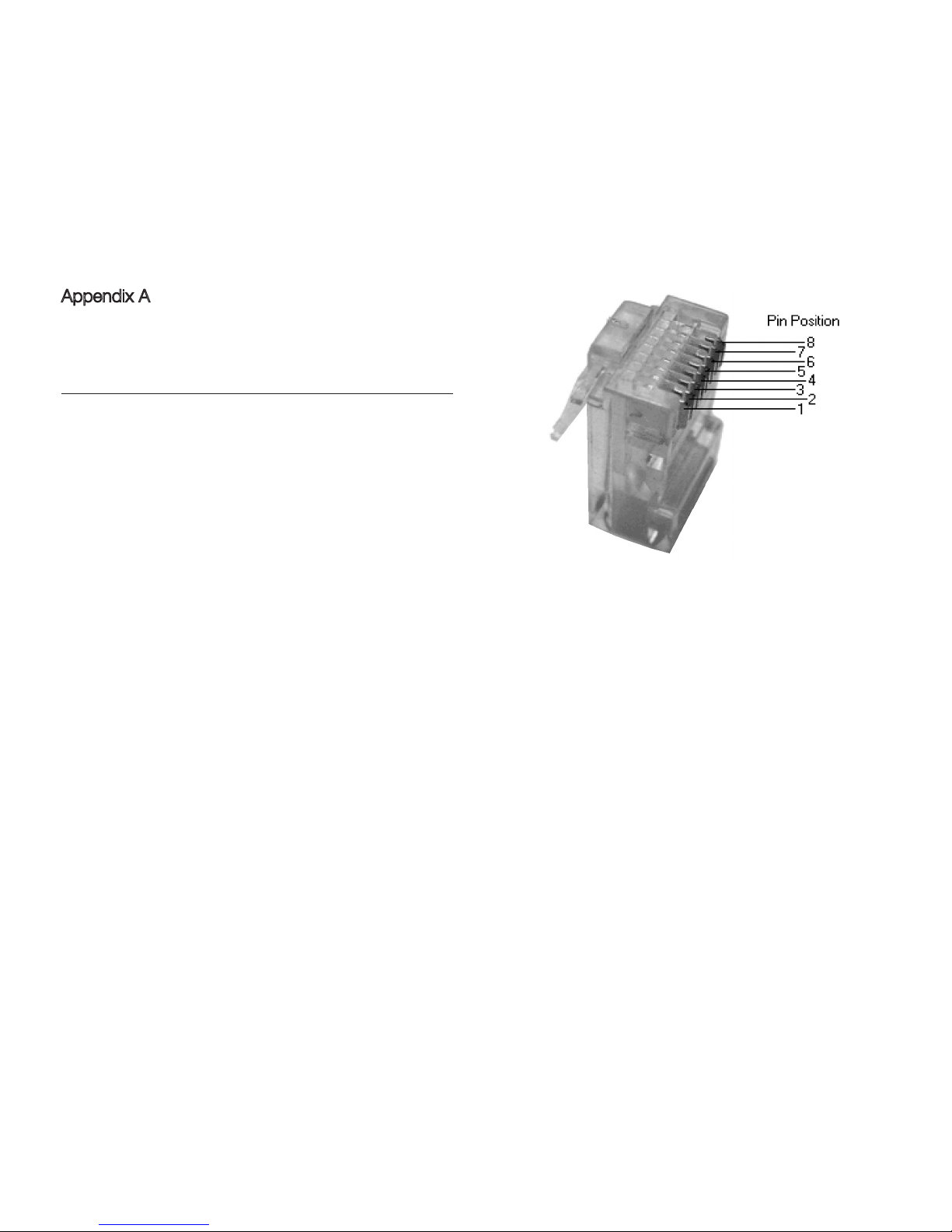
Standard Cat5 or Cat5e cables are used, the same as used for computer networks with RJ45 plug terminations. Do not however crossplug computer networks and TAS link, as damage may result. It should be noted that Cat5/RJ45 cables are not unique to computer
networks and are often used for telephony and other control systems. The cross-plugging issue is not unique to Trilogy products and
Trilogy can take no responsibility for damage caused by failure to follow this instruction.
By using standard Cat5 wiring, users can take advantage of any structured wiring in their buildings.
Bus power
Nominally 10 Volts, bus power is used for external interfaces such as displays. The number of devices connected to the bus should be
discussed with your dealer, as larger systems may require a small additional power supply. Even without displays, power is used by a
number of audio devices that have internal optical isolators. Bus power should not be connected to non-Trilogy equipment.
Bus remote on
This is a 10 Volt remote control signal for Trilogy equipment to power up, by starting their turn on procedure. Usually output by the
Amplier and optically isolated in power amps, the Amplier can be set to receive this signal instead so a different system can deliver the
main power-on signal.
High speed bus
This is a balanced data bus used for devices that require regular and fast communication with the amplier. An example of this is an
external display that needs to update many times a second when adjusting volume. This bus uses industry standard transceivers to offer
best performance over long cable length, but the message format is unique to Trilogy. This bus normally operates continuously, but can
be disabled in the master if there are no devices that need it. Where TAS link loops through a device that does not use the high speed
bus, bus signals are looped locally between connectors and kept well away from audio.
Page 43

Page 44

44
USER MANUAL 925.23102014.V2
Low speed (quiet) bus
This QuietBus is proprietary to Trilogy, both electrically and in the messages that are sent. Developed to serve audio devices that do not
require fast updates, there are three optically isolated signals (LSS/LSW/LSD) which allow the microcontroller in the audio device to turn
off during normal use. The master can briey enable the microcontroller in the audio device to power up/down, or the audio device can
alert the master to a fault which has automatically woken it from sleep. This bus operates infrequently and at 1/100 the frequency of the
fast bus. In normal operation the QuietBus will be completely silent.
Rear Panel LEDs
The use of the rear panel LEDs may change over time. Currently, they are used to indicate,
LED A LSW
LED B LSS
LED C Bus remote
LED D Bus power
LED E Local LSD
LED F Bus LSD
Diagnostics using these LEDs are possible, as part of Trilogy dealer training. You may be asked to look at these LEDs as part of any
telephone support.
Front Panel Warning LEDs
Dots to the right of the front panel display are used to indicate problems. The centre right LED will ash if TAS link attached equipment
capable of error reporting has a problem. Use more / tools / ext status to check which unit has a problem. When looking at individual
unit status, this LED will continue to ash for any units that would produce this warning when on other menu screens.
The top two LEDs on the right will ash if the current drawn on TAS link bus power has exceeded the maximum allowable, 500mA for
more than one second or 1000mA for more than half a second.
Similarly, the bottom two right-hand LEDs will ash if the current drawn on the TAS link remote line has exceeded the specication, which
is the same as the bus power line. Bus power and remote overcurrent will result in that output being switched off and mains power must
be removed from the amplier to clear either of these faults.
Page 45

Page 46
46
USER MANUAL 925.23102014.V2
Appendix A
TAS link Pinout
RJ45 FUNCTION
2
1
Orange/white
White/orange
BUS POWER
0V
6
3
Green/white
White/green
LSW
LSS
4
5
Blue/white
White/blue
DATA +
DATA -
8
7
Brown/white
White/brown
BUS REMOTE
LSD
Page 47

Page 48

48
USER MANUAL 925.23102014.V2
Appendix B
Default Settings
More Time Sleep Sleep Off
More Time Timers All disabled
More Defaults PIN Codes Power Up Use PIN
More Defaults PIN Codes Menu Skip PIN
More Defaults Volume Trim Input X Trim 00
More Defaults Volume Start -60.0dB
More Defaults Volume Max 0.0dB
More Defaults Volume Film -12.0dB
More Defaults Input Input 1
More Defaults Film in No film
More Defaults Balance Bal Centre
More Defaults Display Home On Time
More Defaults Display Home Off Blank
More Defaults Display Timeout 60 secs
More Defaults Display Bright Bright Auto
More Defaults Display dB or 0..99 Vol dB
More Defaults Display Language English 01
More Defaults Mood Light On
More Names Inputs 1Input1 Input 1
More Names Inputs 2Input2 Input 2
More Names Inputs 3Input3 Input 3
More Names Inputs 4Input4 Input 4
More Names Inputs 5Input5 Input 5
More Names Inputs 6Input6 Input 6
More Names Inputs 7Input6 Input 7
Page 49

Page 50

50
USER MANUAL 925.23102014.V2
Cleaning
Dust the unit regularly with a soft cloth or soft brush. For more stubborn marks make sure the unit is switched off and disconnected
from the power supply. Use a slightly damp cloth with a very small amount of mild detergent such as washing up liquid. Do not use a
wet cloth. Never use abrasives or alcohol based agents, they will harm the surface nish. Do not allow the unit to become wet when
cleaning.
Servicing
Your 925 uses thermionic valves (vacuum tubes) for amplication. They are the key component in realising your amplier's very high
performance. Valves have a nite lifespan and will need replacing during the lifetime of the amplier. This lifespan depends on how long
and how hard they are used. In typical use, small signal valves can last for 5000 hours. Frequent switching on and off reduces valve life.
Please bear in mind that some failures can occur early on in a valve’s working life, usually due to mechanical stresses that can occur
during shipping. This is not a reection on the amplier's design but is an inherent characteristic of all valves, and is impossible to predict
even during the amplier's factory burn-in period. The good news is considerate circuit design and modern manufacturing methods
mean that valves are now typically very reliable once established in service.
It is good practice for your dealer to replace the valves in your amplier periodically to prevent sudden loss of a signal path and to
maintain optimum performance. If you are in any doubt your Trilogy dealer will help you assess whether your valves need replacing.
If your amplier exhibits noticeable loss of performance, extreme sensitivity to vibration or becomes excessively noisy then new valves
should be tted by your authorised Trilogy dealer.
There are no user serviceable parts inside. Do not open or attempt to repair the unit. Refer to your authorised Trilogy dealer for servicing.
Declarations
This product is guaranteed against defects in material and workmanship for 3 years from the date of purchase.
This Guarantee excludes valves which are guaranteed for 6 months from date of purchase.
This Guarantee is not transferable and is offered to the original purchaser only.
This Guarantee does not limit your statutory rights within the country of purchase.
Failure to comply with any of the above instructions during installation or operation will render the manufacturer’s warranty null and void.
Marking by the “CE” symbol indicates compliance of this device with the EMC (Electromagnetic Compatibility) and LVD (Low Voltage
Directive) standards of the European Community
This amplier has been tested to ensure that its operation is not adversely affected by normal background levels of radio frequency
interference, and that it does not itself generate excessive amounts of radio frequency energy. If your amplier exhibits sensitivity to
nearby radio frequency devices or is suspected of affecting another device, increase the distance between them. If the problem persists,
consult your Trilogy dealer.
Page 51
51
USER MANUAL 925.23102014.V2
Glossary
Enter Used to select next level of menu structure. Send An output taken before the volume control for
recording or AV loops.
Escape Used to select previous level of menu structure. Return An input back from the recording equipment or AV
loops.
Shaft Encoder The rotary knob, used for volume control and data
entry.
TAS link
Trilogy Audio Systems’ proprietary Link between
products.
Single ended
input
An input with the signal referenced to earth. GPI General Purpose Interface. A control voltage on
TAS link that can be used as an input or output for
connection to non Trilogy equipment.
Balanced input An input with two signals referenced only to each
other.
Bus An interface where many devices share the same
electrical connection.
XLR A professional three pole connector allowing
balanced signal operation.
RJ45 A standard latching connector chosen for TAS link.
Bridge amplier Unusual conguration where the loudspeaker output
is not referenced to earth but is across the output of
two balanced ampliers.
Cat5(e) A standard 4 pair data cable chosen for TAS link.
Page 52
52
USER MANUAL 925.23102014.V2
925 Specications
Inputs
(balanced)
3 pair XLR 3pin female Size 445*430*127 (W*D*H)
Inputs
(single ended)
3 pair RCA phono sockets Size (including
connectors)
445*485*138 (W*D*H)
Inputs
(front panel)
stereo 3.5mm female Size
(packaged)
590*610*250 (W*D*H)
Input impedance
(balanced)
84K Ohms Weight 25Kg
Input impedance
(single ended)
42K Ohms Weight
(packaged)
30.5Kg
Input impedance
(front panel)
42K Ohms Maximum power
consumption
900 Watts
Input sensitivity 600mV for rated output British Model 240V
Send (tape)
outputs
1 pair RCA phono sockets European Model 230V
Gain (Inputs to
Send Output)
0dB USA/Canadian Model 120V
Frequency
response
10Hz-50KHz +/-0.5dB Japanese Model 100V
Rated Power
(8 Ohms)
135 Watts per Channel Storage temperature -20 to +50°C
Rated Power
(4 Ohms)
200 Watts per Channel Operating temperature 0 to +30°C
Distortion Less than 1% A weighted at rated output
into 8 Ohms
Operating Humidity 10 to 80% (no condensation)
Phase Phase correct (non inverting)
SPECIFICATION SUBJECT TO CHANGE
Returns
Should it be necessary for your 925 to be serviced, please send it in the original packaging to your dealer. If this is not possible please
contact us directly and request a Return Authorisation Number. Please mark this number in the space provided on the outer packaging.
Please do not send products back to us without this number as we will not accept liability for the product. If a product is not returned to
us in its original packaging, after servicing we will return it, in Trilogy packaging and a nominal charge will be made.
Page 53

53
USER MANUAL 925.23102014.V2
Whilst the information given in this document is correct at the time of printing, small production changes in the course of our Company’s
policy of improvement through continued research and development might not necessarily be indicated in the specication.
If clarication of any point or specication is required, please refer to your Trilogy dealer.
We welcome your feedback, whether positive or negative, to help us further rene our products.
Please write to;
Trilogy Audio Systems, PO Box 56402, London SE3 7WQ
Please visit our web site; www.trilogyaudio.com
Acknowledgements
Nearly three years in design and development, this current range of Trilogy products are unparalleled in their performance, aesthetics and
system architecture.
Only when a product is technically near perfect, blended with real passion and soul, is it possible for this level of overall performance to
be achieved.
A great many people have worked tirelessly to help achieve this goal, and I would like to take this opportunity to thank Emeka Chigbu,
Nigel Crump, Simon Dart, Cliff Orman, Chris Sims and Simon Quill for their dedication to this project.
© Copyright Trilogy Audio Systems 2014. E&OE
Page 54

 Loading...