

Trillium Panther 2064 Technical & Service Manual
Technical Service Manual
-. ”
:
-.
:
. . .,
.
Technical
Service
Manual
Table of
Contents
:: :::::::::::::: :::: :::: y.:.; :::::::::::::::::: ::::::: ::::::::::::: :::::: ::::::::::::::::::::: :‘.:::::::::::: y:::::-:::::: . . . . . . , . . . . . . . . . . . . . . . . . . . , . . . . . . . . . . . . . . . . . . . . . . . . . . . ,, . . . . . . . . . . . . . . . . . . . . . . . . . . . . . . . . . . . . . . . . . . . . . . . . . . . . . . . . . . . . . . . . . . . . . . . . . ................ ...,.
. . . . . . . . . . . . . . , . . . . . . . . . . . . . . . . . . . . . . . m.. . . . . . . . . . . . . . . . . . . . . . . . . . . . , . . . . . . . . . . . . . . . . . . . . . . . . . . . . . . . . . . . . . . . . . . . . . . . . . . . . . . . . . . . ............... * ......,,
.
Topic
Page
Chapter Introduction
PREFACE . . . . . . . . . . . . . . .,.,,, sI . . . . . . . . . . . . . . . . . . . . . . . . . . . . . . . . . . . . . . . . . . . . . . . . . . s . . . . . . . . . . . . . . i . . . . . ~......................................,.....,...,....... Intro-1
ABOUT THIS CHAPTER.. . . .:.. .
.., ,, ,......... . . . . . . . . . . . . . . . . . . ‘. . . . . . . . . . . . . . . . . . . . . . . . . . . . . . . . . . . . . . . . . . . . . . . . . . . . . . . ,.,. .,.. ..Inno-1
QUICK-REFERENCE CHART.. . . . . . . . . . . . . . . . . . . . . . . . . . . . . . . . . . , . . . . . . . . . . . . . . . . . . . . . . . . . . . . . . . . . . . . . . . Intro-2
Section A - FCC Requirements
RADIO AND TELEVISION INTERFERENCE ...................................................................................................... A- 1
HEARING AID COMPATIBILITY ....................................................................................................................... A- 1
RESPONSIBILITIES ...... .................................................................................................................................... A-2
User Responsibilities ..................................................................................................................................... A-2
Telco Responsibilities .................................................................................................................................... A-2
Section g’-
System Components
STANDARD COMPONENTS.,
............................................................................................................................
B- 1
One Master Key Service Unit
(KSU)
............................................. .: .................................................................. B- 1
One Expander KSU.
.............................................
.:.
......................................................................................
B-2
Up to Sixty-Four Telephone Sets ...................................................................................................................... B-2
Up to Twenty-Eight DSS/BLF Units., ..............................................................................................................
B-3
OPTIONAL COMPONENTS.,
..............................................................................................................................
B-3
Up to Two Door Answer Units ........................................................................................................................ B-3
Up to Five Power Fail Transfer Units., ..........................................................................
).
..................................
B-3
Up to 63 Off Premises Extension/Data Interface (OPX) unit+
.................................. ../ ........... ~‘;.;. ........................... B-4
,One Station Message Detail Recorder (SMDR) Unit., ...........
..-. ..... .
..
;. .:.
......
.;, ........ .:.
......
..:.
.........
..:.
.........
,:
............
B-4
SetStanhs/Wall-Mounts ............. .
......
l...................:. ... ..- ........ . ............................... .: ............... .
........
‘.I
..............
B-4
Desigrtation Cards., ........................................................................ I.. ...... .;. ........................ :. ... .;. ....................... B-5
Section C - Technical Specifications
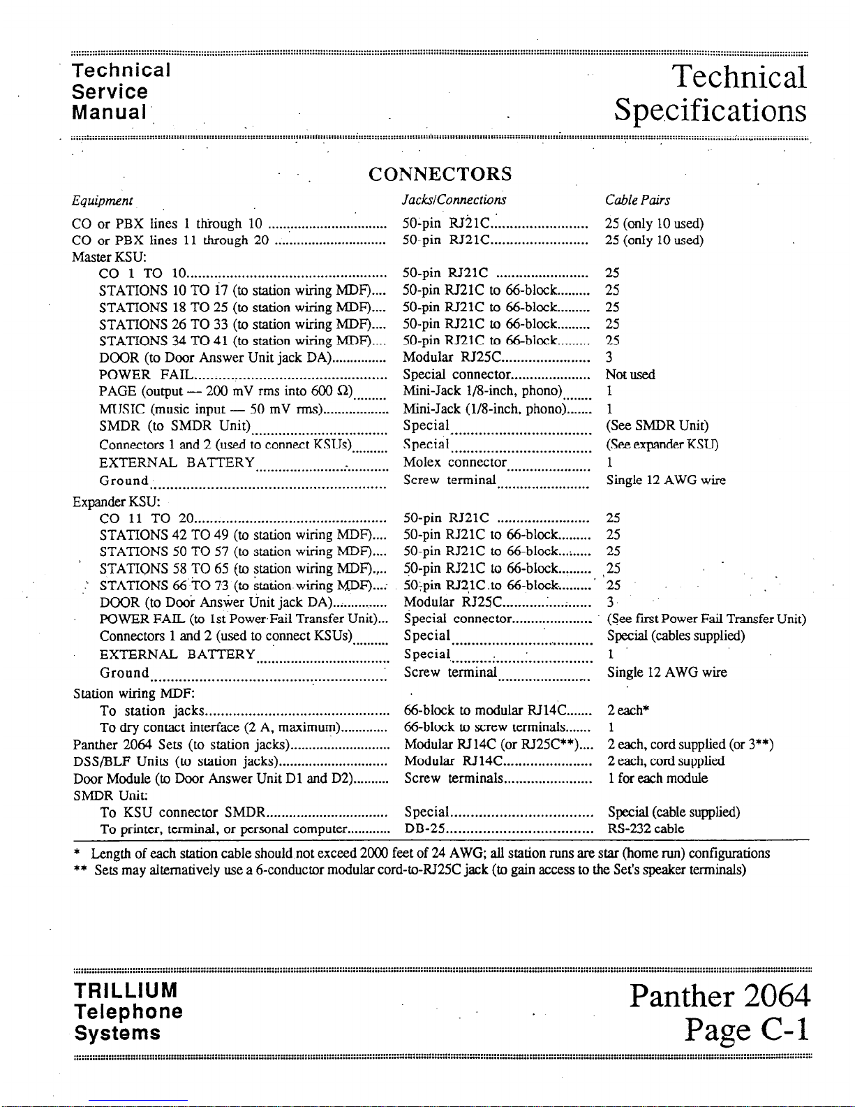
. CONNEmORS
.................................................................................................................................................. C-l
POWER FAIL TRANSFER UNIT CONNECTORS (Optional)
..................................................................................... c-2
SMDR UNIT (Optional) ...................................................................................................................................... C-2
ENVIRONMENTAL REQUIREMENTS ................................................................................................................ C-2
POWER REQUIREMENTS
..................................................................................................................................
C-3
STATION NUMBERING PLAN..
.........................................................................................................................
C-3
SYSTEM CAPABILITIES., .................................................................................................................................
C-3
Section D - Connection Procedures
STEP 1: INSTALLING THE
KSU
................................................................................................................... D-l
Site Preparation. ...........................................................................................................................................
D-l
Backboard Installation,, ................................................................................................................................ D-l
System Uncrating
.........................................................................................................................................
D- 1
Master KSU Installation
................................................................................................................................
D- 1
Expander KSU Installation
............................................................................................................................
D-2
TRILLIUM
Telephone
Systems
Panther 2064
Page i

Table of
Contents
Technical
Service
Manual
>
,; I
Topic Page
Section D
- Connection Procedures (continued)
- STEP2:
CONNECTING INCOMING TELEPHONE LINES . . ............... ;: .................................................... . ....... :D22
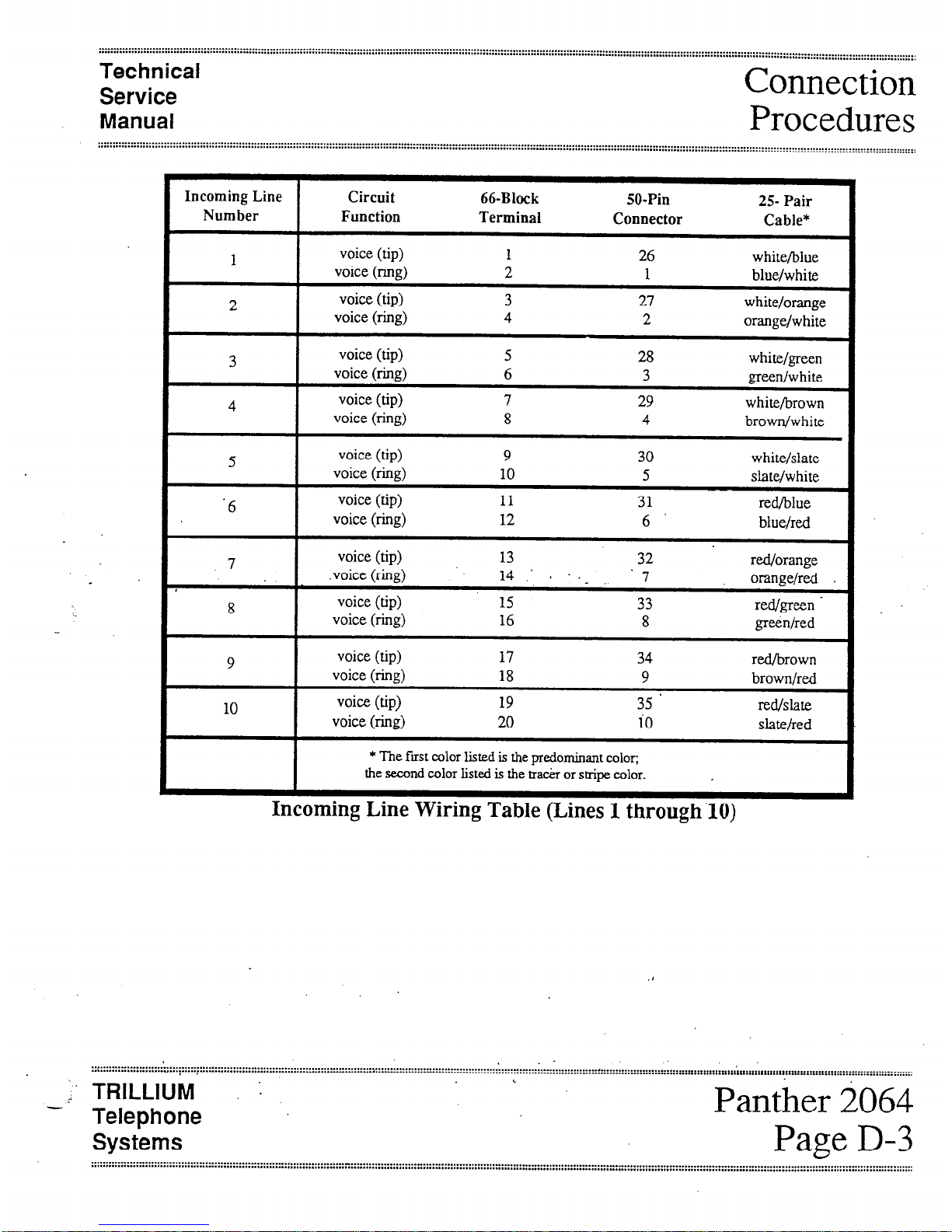
Incoming Line Wiring Table (Lines 1 through 10). ..............................................................................................
D-3
Incoming Line Wiring Table (Lines 11 through 20). ............................................................................................ D-4
STEP 3:
INSTALLING STATION WIRING ..... . . ............................................................................................
D-6
Station Wing Table (Stations 10 through 17). ................................................................................................... D-7
Station Wiring Table (Stations 18 through 25). ................................................................................................... D-8
Station Wiring Table (Stations 26 through 33) .................................................................................................... D-9
Station Wiring Table (Stations 34 through 41). ................................................................................................. D-10
Station Wiring Table (Stations 42 through 49).
.................................................................................................
D-l 1
Station Wiring Table (Stations 50 through 57) .................................................................................................. D-12
Station Wiring Table (Stations 58 through 65). ........................ .
........................................................................
D-13
Station Wiring Table (Stations 66 through 73). ................................................................................................. D-14
STEP 4: CONDUCTING THE INITIAL SYSTEM AND STATION TESTS.. ........................................................ D-15
STEP 5:
CONNECTING THE BACKUP BATTERY ........................................................................................ D-15
STEP 6: CONNECTING DOOR ANSWER UNIT AND DOOR MODULES ..................................................
,:,
....
D-16
Door Answer Unit Installation ........................................................ :. ............................................................ D- 16
Door Module Installation ........................................ .
....................................................................................
D-16
Door Answer Unit Test.. ............................................................................................................................. D-17
STEP 7: CQNNECXING THE MUSIC SOURCE ............................................................................................. D-18
Music Connection .....................
:
D-18 $ ,i
.
Music Test ..... :.: ..:.
..................................................................................................................
.............. . ................ . .... .:,. ........... . ............ . ..... . ....... . ..... :: ... . * ...... .+ ... . ....... . ......... . ................ D;18.
STEP 8:
CONNECTING THE EXTERNAL PAGING EQUIPMENT.. ................ .:.
...........................
.:. ................. D-19
Equipment Connection ...................................................... .: ......................................................................... D-19
Paging Test.. .......... (............. ....................................................................................................................... D-19
..
STEP 9:’
CONNECTING AN EXTERNAL LOUD BELL .............................................................................. .: .. D-20
Equipment Connection ................................................................................................................................ D-20
Loud Bell Test ....... .: .................................................................................................................................. D-20
STEP 10:
CONNECTING THE OPX UNIT, ..................................................................................................... D-2 1
OPX Unit Connection,, .............................................................................................................................. D-21
OPX Unit Test ........................................................................................................................................... D-21
STEP 11: CONNJXTING THE SMDR INTERFACE UNIT ................................................................................ D-22
SMDR Interface Unit Installation., ............................................................................................................... D-22
SMDR Interface Unit Test.. ......................................................................................................................... D-22
SMDR Printout Formats .............................................................................................................................. D-22
STEP 12: CONNECTING THE POWER FAIL TRANSFER UNITS ...................................................................... D-23
Power Fail Transfer Unit Installation
..............................................................................................................
D-23
Power Fail Transfer Unit Test ....................................................................................................................... D-27
STEP 13: INSTALLING AN EXTERNAL AMPLIFIER ..................................................................................... D-28
Panther 2064
Page ii
TRILLIUM a --
Telephone
Systems
Technical
Service
Manual
Table of
Contents
::::::::::::::::::: j: ::::,::: ~ ::::::::::::::::::::: i ~~~~.~“..“.......... _...- . . . . . . . . . . . . . . . . . . . . . . . . . . . . . . . . . . . . . . - . . . . . . . . . . . . . . . . . . . . . . . . . . . . . . . . . . . . . . . . . . . . . . . . . . . -...- . . . . . . . . . . . . . . . . . . ..-................ _ . . . ..__....__..._...~..~.~..~~~~~~~~.~~. _ __.. I . .._....__.
. . . . . . . . . . . . . . . . . . . . . ..~..................... :‘........ ‘ . . . . . . . . . . . . . . . . . . . . . . . . . . . . . . . . . . . . . . . . . . . . . . . . . . . . . . . . . . . . . . . . . . . . . . . . . . . . . . . . . . . . . . . . . . . . . . . . . . . . ............... _ ._......_....._._,...........-.-
.._........
,
.
Topic
Section E - System and Set Layout
Page
TYPICAL MASTER KSU LAYOUT DIAGRAM (Standard Components only)
..................................................
. ... .._ .......
E-l
TYPICAL MASTER KSU LAYOUT DIAGRAM (Standard Components bnly).
.............................................................. E-2
TYPICAL SYSTEM LAYOUT DIAGRAM (Optional and External Components only).
................................................... E-3
SET LAYOUT DIAGRAM. ..................................................................................................................................
E-4
SET LAYOUT.
...................................................................................................................................................
E-5
DSS/BLF UNIT LAYOUT DIAG RAM.
..................................................................................................................
E-6
TYPICAL POWER FAIL TRANSFER UNIT LAYOUT DIAGRAM
..........................................................................
E-7
Section F - Feature Programming
FEATURE CATEGORIES
...................................................................... I..
........................................................... F-l
Categories Versus Codes,, ....................................................................................
:
.........................................
F-l
Referencing Categories to Codes..
................................................................................................................... F-l
Interrelated Features .......................................................................................................................................
F-l
Feature Programming Cross-Reference Table,.
.................................................................................................... F-2
SYSTEM-WIDE FEATURES
..... . . .....................................................................................
:. .................................. F4
System-Wide Feature Programming Table ......................................................................................................... F-5
INDIVIDUAL SET FEATURES ..........................................................................................................................
F-10
Individual Set Feature Programming Table
...................................................................................................... F-11
INDIVIDUAL LINE FEATURES .........................................................................................................................
F-14
Individual Line Feature Programming Table
......................................................................................................
F-15
INDIVIDUALGROUP FEATURES
................................................
*,
..........................................................................
F-18.
IndividualGroup&at&ProgramkngTable
. ..i..
............................
.I ......... :: ..:. ....... . ........ l....‘.....:.
....
:.......‘.......:.
... ‘F-19
CALL RESTRICTIONS
...................................................................................................................................... F-20
Call Restiction Feature Programming Table .. .I ......................... :. .......................................................................
F-21
Yerifying Call Restrictions.
.........................................................................
:.
.................................................
F-22
SPEED CALL NUMBERS..
........................................... .: ..................................................................................... F-24
Speed Call Programming Notes.. ....................................................................................................................
F-24
Common Speed Call Numbers .......................................................................................................................
F-24
Private Speed Call Numbers ..........................................................................................................................
F-25
FEATURE DESCRIPTIONS ..................... :. ........................................................................................................
F-2.5
Section G - Operating Instructions
OPERATING lNSTRUCTIONS TABLE.. . . . . . ., , .~ . . . . . . . . . . . . . . . . . . . . . . . . . . . . . . . . . . . . . . . . . . . . . . . . . . . , . . . . ,. . . . .., G-l
Section H
- Troubleshooting
TROUBLESHOOTING TABLE
,,,,,,,.,,...,.....,.,.,............1..,,.....I.....I...I.I..,~I.............I.II.......I.......,.,.,,,,,.,,.,,,,,,,.,..,,.
H-l
TRILLIUM
Telephone
Systems
Panther 2064
Page iii .
Technical ’
Service
Manual
Chapter
Introduction
:!; :::::::::::::::::::::::::::::::::::::::::::::::::::::::::::::::: : :::::::::::::::::::::: ::::::::::::::::::I::::::::::::::::;:::::::::::::::..... . . . . . . . . . . . . . . . . . . . . . . ----*...* . . . . . . . . . . . . . . . . . -.--,..-..* . . . . . . . . . . . . . . . . . . . . . . . . . . . . . . . . . . . . . . ..-..........................
a
..: . . . . . . . . . . . . . . . . . . . . . . . . . . . . . . . . . . . y....................... a . . . . . . . . . . . . . . . . . . . . . . . . . . . . . . . . . . . . . . . . . . . . . . . . . . . . . . . . . . . . _ . . . .
PREFACE
.
ABOUT, THIS CHAPTER.
The Panther 2.064 Electronic Key Telephone System is a
state-of-the-art system that incorporates sophisticated electronics to meet the communications needs of today’s office
and business user.
It connects up to 20 outside tone or rotary telephone lines
(one or two optional Door Answer Units and Door Modules
may be installed reducing the number of outside lines served
on a l-for-l basis) with up to 64 station Sets - which are
all wired in a star configuration. The master key service unit
(KSU) can handle 10 outside lines and 32 internal stations;
with the expander KSU, the system can handle its full complement of outside lines and internal stations. Both
Handsfree and Non-Ha&free Sets are available. A separate
Direct Station Select/Busy Lamp Field @SS/BLF) Unit is
available for use at an attendant station; it contains station
select keys and indicators that show the status of all system
stations.
Attendant calling, common and private speed calling, call
transferring, transfer ringing, door answering (with optional
Door Answer Units and Door Modules), conferencing (up to
3 parties), message waiting, internal intercom paging (station-to-station; zone, and all page paging), .external
ioudspeaker paging, call detail and account code recording
(through an optional SMDR unit), and last number redialing .
are just some of the many features offered.
In addition, the Panther system is designed to allow easy interfacing with modems and answering devices through an
optional OPX device.
The fully sealed Panther 2064 Electronic Key Telephone
System may be installed in either a standalone mode or behind a CENTREX or PBX.
An optional external backup 24 V battery can be connected
to each KSU in the system: the backup batteries are auto-
matically brought on line in the event of a power failure,
thus preventing interruptions in telephone service.
Also, in the event of a total system failure, incoming lines
will be transferred to standard sets if optional Power
Transfer Units have been installed in the system.
This chapter has also been designed specifically to enable
technicians to install, operate, and maintain the Panther 2064
Electronic Key Telephone System. Information is presented
in a logical order, without undue wordiness - to help the
technician find, understand, and use the relevant information, quickly and easily.
Therefore, for example, the Connection Procedures are sep-
arated into concise steps that have a logical and necessary
sequence; and reference material (Technical Specifications,
Feature Programming, Operating Instructions, and
Troubleshooting) is presented in a variety of easy-to-follow,
visible-at-a-glance tabular formats.
To acquaint yourself with this chapter, please review the
Table of Contents and spend a few moments browsing
through the different sections.
CAUTION
Panther equipment is sealed. Breaking the seal
will void your warranty.
If you have an installation, operation, or troubleshooting
problem that you cannot solve by using thischapter (and ‘.
that your dealer cannot help solve),. call TRILLIUM
Customer Service at 1-800-848-2444 (inside California, call
1-800-422-7600).
NOTE
For your ready reference, a chart summarizing
indicator signals appears on the back of this
page.
TRILLIUM
Telephone
Systems
Panther 2064
Page Intro- 1
Chapter Chapter
Technical Technical
’ Introduction, ’ Introduction,
Service Service
Manual Manual
:::::::I::~:::::::::(:::::::::::::::::::::::::::::::::::::::::::~::::::::::::::::::::::::::::::::~:::::::::::::::::::::::
. . . . . . . . . . . . . . . . . . . . . . . . . . . . . . . . . . . . . . . . . . . . . . . . . . . . . . . . . . . . . . . . . . . .
:::::::I::~:::::::::(:::::::::::::::::::::::::::::::::::::::::::~::::::::::::::::::::::::::::::::~::::::::::::::::::::::: . . . . . . . . . . . . . . . . . . . . . . . . . . . . . . . . . . . . . . . . . . . . . . . . . . . . . . . . . . . . . . . . . . . .
. . . . . . . . . . . . * . . . . . . . . . . . . . . . . . . . . , . . . . . . . . . . . . . . . . . . . . . . . . . . . . . . . . . ::::: :;:; :::::i::::::::;::::l:: :::: ::
:::::;::::::::::::::::::::::::::::
::::!: ::::::
. . . . . . . . . . . . * . . . . . . . . . . . . . . . . . . . . , . . . . . . . . . . . . . . . . . . . . . . . . . . . . . . . . . ::::: :;:; :::::i::::::::;::::l:: :::: ::
:::::;::::::::::::::::::::::::::::
::::!: ::::::
.
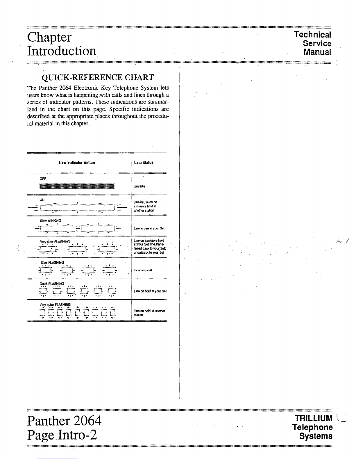
QUICK-REFERENCE CHART
*
The Panther 2064 Electronic Key Telephone System lets
users know what is happening .with calis and lines through a
series of indicator patterns. These indications are summarized in the chart on this page. Specific indications are
described at the appropriate places throughout the procedu-
ral material in this chapter.
Lii hdlcatar Action Lii stahts
OFF
I
line ide
ON
I
-c.w.-. . . . . ;.-.,... M,......v.... c . ..I *v. . . ..w - pw...“..,- -
1 Llnain”samm‘
-:
i-1
exdtie hold a
- . . . . . . . y.” . . . . . _ .I.. _ . . . . . . . . . . ..Y” . . . . . . . . . . . . . . ..- A..r.r.m -
0
1 motwstadm
I
Slow WINKING
I
- ..-- . ..! .
.
- (..,.,,
. . ..--.......__..........-..-.! .I.. F,.ll..*l.,-
- ::
i-i
,: _
-: .,.,.......,....... . . . . . . . . . i.- -: . . . . . . . . . . . . . . . . ..\.....\.... i -
- I - - I -
/ LiwinuseatyarSet
Vq dor, FIASWG
1, tin, on erdusive hdd
I
.:,- >.,.!y..,.
..I .
..vIIU” ,,.,... . . . . -....!...:.,. .
at you set; line uals-
._ _: + .+ L -I’
i- ‘ I
‘+-Y--
. ..-....-...~. -
..,. ;-y-e+-.
felledbaa to y~~sei:
or c&a& lo you set
~oy”SHlNG
\ 1 ,
. . . . . . . ,t.!..:., ,:..!I, . . . . .
2 :- _:
.: . . . . . . . . I
& -;
. . . ..,
:>
&,..,.“..L
‘L -)
lnmrmgd
, I *
’ t *
.&...-I “;..~~‘~
* I *
:::::::::::::::::::::::::::::::::::::::::::::z ::::::::; :::::::::::::::; :::::::::::::::::::::::::::::::::::::::..................................................................................................................................................................
. . . . . . . . . . . . . . . . . . . . . . . . . . . . . . . . . . . . . . . . . . . . . . . . . . . . . . . . . . . . . . . . . . . . . . . . . . . . . . . . . . . . . . . . * . . . . . . . . . . . . . . . . * . . . . . . . . . . . . . . . . . . . . ..... * .........,..........,.........
PQnthPl
1 cLluw/r 2064
Page .Intro-2
TRILLIUM ‘x. _
Telephone
Systems
Technical
Service
Manual
.
~-- ----- . . . . - . . . . . . . . . . . . ..._” . . . . . . . ii..
FCC
Requirements,
RADIO AND TELEVISION
INTERFERENCE
I’
WARNING
HEARING AID COMPATIBILITY
The Panther 2064 Elecnonic Key Telephone
System generates and uses radio-frequency energy and -
if not installed and used in strict
accordance with these instructions - may
cause interference to radio and television
reception.
The Panther 2064 Electronic Key Telephone System has
been certified to comply with the limits for a Class B com-
, puting device, pursuant to Subpart J of Part 15 of the Federal
Communications Commission (FCC) Rules which are designed to provide reasonable protection from radio and
television interference in a residential installation. However
there is no guarantee that interference will not occur in a
particular installation.
If interference is encountered, test to determine if the unit is
at fault by unplugging the Key Service Unit (KSU) from the
wall outlet.
‘If unplugging the KSU removes ‘the interference, try the foil
lowing corrective measures, singly or .in combination, until
the interference is eliminated:
.
Change the location or position of the indoor receiving antenna of the radio or television.
.
Relocate the Panther 2064 Set or KSU in relation to
the radio and television receivers experiencing
interference.
.
Plug the KSU into an outlet that does not also serve
radio or television sets.
If further help is needed, consult your TRILLIUM dealer or
an experienced radio/television technician - or refer to the
FCC’s booklet, “How to Identify and Resolve Radio-TV
Interference Problems.‘* It is available from the US
Government Printing Office, Washington, DC 20402 (stock
number 004400403454).
The Panther 2064 Set is compatible for those requiring a
hearing aid as defined in section 68.316, Part 68 of FCC
Rules.
TRILLIUM
Telephone
Systems
._._._....,......................................................,...................................................................................................................................... a . . . . . . . . . . . . . . . . . . . . . . . . . . . . . . . . . . . . . . . . . . . . . . . . . . . . . . . . _ _......_......
. . . . . . . . . . . . . . . . . . . . . . . . . . . . . . . . . . . . . . . . . . . . . . . . . . . . . . . . . . . . . . . . . . . . . . . . . . . . .I.. . . . . . . . . . . . . . . . . . . . . . . . . . . . . . .
. . . . . . . . . . . . . . . . . . . . . . . . . . . . . . . . . . . . . . . . . . . . . . . . . . . . . . . . . . . . . . . . . . . . . . . . . . . . . . . . . . . . . . . . . . . . . . . . . . . . . . . . . . . . . . . . . . . . . . . . . . . . . . . . . . . . . . . . . . . . . . . . . . . . . ...... . . . . . . .
FCC
Technical
Service
.
Requirements
Manual
.
. . . . . . . . . . . . . . . . . . . . . . . . . . . . . . . . . . . . . . . . . . . . . . . . . . . . . . . . . . . . . . . . .$. . . . . . . . .
. . . . . ...” . . . . . . . . . ~ . . . . . . . . . . . . * . . . . . . . . . . .
. . . . . . . . . . . . . . . . . . . . . . . . . . . . . .
::::::::::::::::::::::::::,::::::::::::::::::::;:~::::;;:::~::::::::~:::::::::::::::::~:::~:::::~::~:::::~::::::::::::::::::::::::::::::::::::::::::::::::::::::::::::::::::~:::::::::::::::::::::
,
’
RESPONSIBILITIES Telco Responsibilities
The telephone company is required to give you adequate no-
tice of any changes it makes in its .technical operations or
procedures that may affect the compatibility or use of your
Panther 2064 Electronic Key Telephone System.
The FCC’s rules permit the Panther 2064 Electronic Key
Telephone System to be connected to the telephone network
. via a jack or jacks provided by the telephone company
(telco). These jacks are not provided for coin or party lines.
User Responsibilities
Before connecting your Panther 2064 Electronic Key
Telephone System to the telephone lines, you must contact
the telephone company and provide them with the following
information:
.
Telephone numbers of the lines to which the
Panther 2064 Electronic Key Telephone System is
to be connected (lines 1 through 20)
.
FCC Registration Number (found on the side of the
Key Service Unit or KSU: the number for the
Panther 2064 system - with or without the expander KSU - is EBS78T-71737-KF-E)
.
Ringer Equivalence Number (also found on the side
of the KSU: the number for the Panther 2064, with
‘or without,the expander KSU, is 33B)* i
.
USOC jacks required (usually one !O-conductor
RI21 jack to each KSU; therefore, h~o RI21 jacks
are required if the expander KSU is installed )
.
Facility Interface Code (the code for the Panther
2064 Electronic Key Telephone System is 02LS2)’
l
Service Code (the code for the Panther 2064
Electronic Key Telephone System is 9.OF)
You also have the responsibility to disconnect a malfunctioning Panther 2064 Electronic Key Telephone System
from the telephone lines until the cause of the malfunctioning is identified and repaired. Otherwise, the telephone
company may temporarily disconnect service.
* The Canadian Department of Communications load number for the Panther 2064 Electronic Key Telephone System
is 16B.
Panther 2064
Page A-2
TRILLIUM i. -
Telephone.
Systems
.........................................................................................................
....................................................................................................
..... . . . . . . . . . . . . . . . . . . . . . . . . . . . . . . . . . . . . . . . . . . . . . . . . . . . . . . . . . . . . . . . . . . . . . . . . . . . . . . . . . . . . . . . . . . . . . . . . . . . . . . . . . . . . . . . . . . . :::::::::::::::::::::::::::::::::::::::::~::::::::::
System
Components.
Technical
Service
Manual
,......_..____......................................
. . . . . . . . . . . . . . . . . . . . . .
. . . . . . . . . . . . . . . . . . . . . . . . . . . . . . 2.y.. . . . . . . . . . . . . . . . . . . . ..a....-... ~ . . . . . . . . . . . . . . . . . . . . .
. . . . . . . . . . . . . . . . . . . . . . . . . . . . . . . . . . . . . . . . . . . . . . . . . . . . . . . . . . . . . . . . . . . . . . . . . . . . . . . . . . . . . . . . . . . . . . . . . . . . . . . . . . . . . . . . . . . . . . I . . . .
.......................................................................-.....................
:
. . . . . . . . . . . . . . . . . . . . . . . . . . . . . . . . . . . . . . . . . . . . . . . . . . . . . . . . . . . . . . ..a . . . . . . . . . . . . . . . . .,..,... . . . . . . . . . . . . . . . . . . . . . . . . . . . . . . . . . . . . . . . . . . . . . . . . .......................
,
One Expander KSU
Part Number 90-0287
(tone/rotary)
The expander (KSU for the Panther 2064 Electronic Key
Telephone System can also be programmed to operate with
either DTMF or rotary (pulse) signaling. The signaling on
each CO line can be programmed independently.
The expander KSU has one 50-pin connector on its right
side (labeled CO11 to CO20) to attach ten more incoming
telco CO lines (line 20 must be left vacant if a second optional Door Answer Unit is insta.lIed).
Also on the right side of the master KSU are connectors labeled POWER FAIL (used for the optional Power Fail
Transfer Unit), and DOOR (used for the optional Door
Answer Unit).
Near the bottom left of the expander KSU are four 50-pin
connectors, labeled STATIONS 42 TO 49,50 TO 57.58 TO
65, and 66 TO 73 that are used to connect the KSU to the
station wiring main distribution frame (MDF) - and,
through the MDF, to stations 42 through 73.
Two connectors are available at the bottom of the expander
KSU that are used to con&t it to the master KSU.
The expander KSU has its own separate power cord ‘(at the
top of the KSU) that plugs into a 110 V ac outlet (but only at
the appropriate time; ‘see the Connection Procedures section). A separate grounding wire (12 AWG, solid copper)
which connects to the top of the expander KSU must be attached to a ground clamp, usually on a water pipe.
An input connector (labeled EXTERNAL BATTERY) for a
separate 24 V dc backup battery is also provided at the top
of the expander KSU. If ac power is lost, the switchover to
battery power is automatic when the optional backup battery
for the expander KSU is connected
The unit comes a mounting bracket and four screws for in-
stalling the expander KSU over (in front of) the master KSU
(on the backboard).
.
Up to Sixty-Four Telephone Sets
Part Number 90-Q288
(non-handsfree) .
Ert Number 90-0225
(handsfree)
Other than the handsfree operation, these two models look
alike and operate identically. For example, both have an attractive black matte finish.
Each Set’s base has twenty line select keys (labeled 1
through 20). eight dedicated function keys (labeled .Hold,
Flash/Cancel, Conference, Intercom, Redial, Speed,
Speaker, and Mic.on/off) and a tone dial keypad
The line keys, the Intercom key, and the Mic.on/off key
have accompanying status indicators.
Finally, the base has a speaker volume control (a sliding adjustment) and a ringer control switch (a 3-position switch,
for low, medium, and high volume ringing).
ifs ,,
.’ Each Set also includes a telephone handset and two .modular ’
cords - a 4;conductor, coiled cord for connecting the handset to the Set, and a 4-conductor modular cord for.
connecting the Set to the station wiring jack.
Panther 2064
Page B-2
TRILLIUM t _
Telephone
Systems
:::::::::::::::::::::::::::::::::::::::::::::::::::::::::::::::::::: :u:::::::::; ::::::::: :::::::::::::: ::::::; . . . . . . . .
. . . . . . . . . . . . . . . . . . . . . . . . . . . . . . . . . . . . . . . . . . . . . . . . . . . . . . . . . . . . . . . . . . . . . . . . . . . . . . . . . . . . . . . . . . . . . . . . . . . . . . . . . . . . . . . . . . ................-.-..-___-
. . . . . . . . . . . . . . . . . . . . . . . . . . . . . . . . . . . . . . . . . . . . . . . . . . . . . . . . . . . . . . . . . . . . . . . . . . . . . . . . . . . . . . . . . . . . . . . . . . . . . . . . . , . . . . . . . . . . . . . . . . .......................-...-
Technical
System
Service
Manual _
Compdnents
::::::::::::::,::::::::::::::::::::::::::::::::::::::::::::~::::::::::::::::::::::::::::::::::::::::::::~:::::::::::::=:::~:
. . . . . . . . . . .._............................................... . . . . . . . . . . . . . . . . . . . . . . . . . . . . . . . . . . . . . . . . . . . . . . . . . . . . . . . . . . . . . . ,.i . . . . . . . . .
. . . . . . . . . . . . . . . . . . . . . . . . . . . . . . . . . . . . . . . . . . . . . . . . . . . . . . . . . . . . . . . . . . . . . . . . . . . . . . . . . . . . . . . . . . . . . . . . . . . . . . . . . . . . . . . . . . . . .
. ..* . . . . . . . . . “...
::::
Up to Twenty-Eight DSS/BLF Units
.
Part Number 90-0226
The DSS/BLF utiit has 64 keys and indicators, labeled
10
through 73 - one for each possible station in the system.
The D_CC,‘!!?T.F *:+.-Set. pa& (also kcown BS attendant sta-
tion sets
- but not to be confused with the master station)
allow the user/attendant to select the desired station by
pressing one of the 64 direct station select (DSS) keys and to
observe the status of each station by observing the corresponding busy lamp field (BLF) indicator.
The DSS keys can also be programmed to select speed call
numbers - keys 10 through 19 can be used to dial the first
ten of the attendant’s private speed call numbers; and keys
20 through 73 can be used to dial the corresponding first 54
of the system’s 80 common speed call numbers (codes
20
through 73).
These units - which require an accompanying Set - are
assigned a station number and, therefore, reduce the maximum number of sets possible on a l-for-l basis.
For example; a system with.a single DSVJ3LF unit
5 colild have ,a m&mum of 63 S&s (including the Set
paired with the DSS/BLF.unit).
Alternatively, a system could have as many as 28 DSS/
BLF units, all reqdiring an accompanying Set; this system would have 36 Sets, 28. of which would be part of
an attendant station.
Each DSS/BLF unit includes a 4conductor modular cord for
connecting the unit to the station wiring jack..
Each DSQ’BLF unit also comes equipped with a Designation
Card (used to record station locations/assignments) - and
with a plastic cover that protects the Designation Card.
OPTIONAL COMPONENTS
Up to Two Door Answer Units,
Part Number 90YO058,
With One or Two Door Modules Each,
Part Number 90-0057
The Door Answer Unit (also known as the Door Answer
Control) is installed next to, and connects with, the KSU. It
serves as the interface between the system’s stations and the
one or two installed Door Modules (also know as the Door
Answer Boxes) at the desired doors or entryways. The first
Door Answer Unit uses line IO and the second, if instiled,
uses line 20.
Together, the Door Answer Units and iheir corresponding
Door Modules enable signaling and conversation between
Set users and visitors. Like the KSUs, all these units come
equipped with mounting Screws.
A visitor, by pressing the door bell button on a Door
Module, generates a distinctive tone (four groups of 4 short
tones for Door Module 1, four groups of 2 long tones for
Door Module 2) that will sound at all Sets programmed to
- ring on, line 10. or 20 and line 10 or line 20. indicator
WINKS, depending on which line the coqesponding- poor
Answer Unit is installed on. Also, each Set user can gencntc
a calling tone that will sound at Door Module 1 only.
Up to Five Power Fail Transfer Units
Part Number 90-0052
The Power Fail Transfer Unit automatically takes over in the
event of an electrical power failure, allowing for continued
telephone service during the emergency. One Power Fail
Transfer Unit can handle up to 4 incoming lines.
When power fails, the Power Fail Transfer Units transfer in-
coming CO lines (up to all 20 of them - or the 18 or 14,
lines in use, if the optional Door Answer Units with Door
Modules are installed) to pre-installed
standard
telephone
sets (not to Panther 2064 Sets).
TRILLIUM
Telephone .
Panther 2064
Systems
Page B-3
. . . . . . . . . . . . . . . . . . . . . . . . . . . . . . . . . . . . . . . . . . . . . . . . . . . . . . . . . . . . . . . . . . . . . . . . . . . . . . . . . . . . . . . . . . . . . . . . . . . . . . . . . . . . . . . . . . . :::::::y:::::::::::::::: ::::::::::::::: c :::::.; ::::::::::::::::::::::::::::: “$” .::::::::::::::::::::;
:::::::::::::::::::::::::::::::::::::::::::::
;:::,:*:
. . . . . . . . . . . . . . . . . . . . . . . . . . . . . . . . . . . . . . . . . . . . . . . . . . . . . . . . . . . . . . . . . . . . . . . . . . . . . . . . . . . . . . . . . . . . . . . . . . . . . . . . . . . . . . . . . .

System .
Components
,
Technical
Service
Manual
.’
. . . . . . . . . . . . . E . . . . . . . . . . . . . . . . . . . . . . . . . . . . . . . . . . . . . . . . . . . . . . . . . . . . . . . . . . . . . . . . . .
,............
. . . . . . . . . . . . . . . . c . . . . . . . . . . . . . . . . . . . . . . . . . . . . . . . . . . . . . . . . . . . . . . . . . . . . . . . . . . . . . . . . . . . . . . . . . . . . . . ” . . . . . . . . . . . . . . . . . . . . . . . . . . . . .................................................................
. . . . . . . . . . . . . . . . . . . . . . . . . . . . . . . . . . . . . . . . . . . . . . . . . . . . . . . . . . . . . . . . . . . . . . . . . . . . . . . . . . . . . . . . . . . . . . . . . . . . . . . . . . . . . . . . . . . . . . . . . . .....................................-................................................................................................
I.
a .
.
Set Stands/Wall-Mounts
Part Number 90-0087
Each Set may be placed on a desk - or mounted on a wall
using the Set Stand/Wall-Mount Bracket (available in pack-
ages of 10).
Up to 63 Off Premises Extension/
Data Interface (OPX) units
Part Number 90-0308
The OPX unit converts a 4-wire interface to a 2-wire interface, allowing a single line telephone to be connected to any
spare station jack - except station 10. It also allows 2-wire
devices to be connected at a distance greater than the system
2000 feet limit for Sets. The OPX unit also simulates CO
line characteristics, allowing a modem or an answering ma-.
chine to be connected to the system. Finally, the OPX unit
allows a remote device to be connected to your system at
any distance via a CO line.
When the user lifts the single-line telephone’s handset, an in-
tercom connection is made to the Panther system. Also, by
dialing a special code, the off-premise user can access any
of the Panther system’s outside lines.
One Station Message Detail Recorder
(SMDR) Unit
Part Number 90-0227 only
-
This unit ‘allows information .on system, line, and station’
.
usage to be captured and recorded.
The same bracket can also be used to provide a heightened
viewing angle when used with the Set on a desk- or table-
top.
Panther 2064
Page B-4
TRILLIUM f,,
Telephone
Systems

. . . . . . . . . . . . . . . . . . . . . . . . . . . . . . . . . . . . . . . . . . . . . . . . . . . . . . . . . . . . . . . . . . . . . . . . . . . . . . . . . . . . . . . . . . . . . . . . . . . . . . . . . . . . . . . . . . . . . . . . . . . . . . . . . . . . . . . . . . . . . . . . . . . . . . . . . . . . . . . . . . . . . . . . .___._. . . . . . . . . . . . . . . . . . . . . . . . . . . . . . . . . . . . _._.. . . . . . . .._ . _. . . . . . . . . . .
. . . . . . . . . . . . . . . . . . . . . . . . . . . . . . . . . . . . . . . . . . . . . . . . . . . . . . . . . . . . . . . . . . . . . . . . . . . . . . . . . . . . . . . . . . . . . . . . . . . . . . . . . . . . . . . . . . . . . . . . . . ..................... . ...............,...............................,.............................................. : ...............
_. _. . . . . . ... .__.
Technical
Service
System
Manual
.
Components
. . . . . . . . . . . . . . . . . . . . . . . . . . . . . . . . . . . . . . . . . . . . . . . . . . . . . . . . . . . . . . . . . . . . . i . . . . . . . . . . . . . . . . . . . . . . . . . . . . . . . . . - . . . . . . . . . . . . . . . . . . . . . . ...................
...................................................................................................,.............-..
. . . . . . . . . . ...” . . . . . . . . . . . . . . . . . . . . . . . . . . . . . . . . . . . . . . . . . . . . . . . . . . . . . . . . . . . . . . . . . . . . . . . . . . . . . . . . . . . . . . . I . . . . . . . . . . . . . . . . . . . . . . . .
......................................................................................
:
....................,.....................-.
--:=
.
The Designation Card for DSS/BLF units is used to itiy
the assignment or location of the’64 system stations irznbered 10 through 73) and for recording speed call nurnkrs
- the first 10 private numbers in spaces 10 through 1 Sr and
the fust 54 common numbers in spaces 20 through 73.
”
Designation Cards
Part Number 90-0300
(for Panther 2064 Sets)
and
Part Number 90-0301
(for DSS/BLF units)
The Designation Card for Sets (the same Designation Card
is used for both non-handsfree and handsfree Sets) is used to
list the telephone numbers of the incoming lines.
Although each Set comes equipped with one installed and
one spare Designation Card, you may order additional cards
(in packages of 10) for your system.
Although each DSS/BLF unit comes equipped with oxz installed and one spare Designation Card, you may cxder
additional cards (in packages of 10) for your system.
Notice that the Set and the DSS/BLF unit use
d#uenf
Designation Cards.
TRILLIUM
Telephone
Systems
Panther 2064
Page B-5
. . . . . . . . . . . . . . . . . . . . . . . . . . . . . . . . . -. . . . . . . . . . . . . . . .
. . . . . . . . . . . . . . . . . . . . . . . . . . . . . . . . . . . . . . . . . . . . . . . . . . . . . . . . . . . . . . . . . . . . . . . . . . . . . . . * . . . . . . . . . . . . . . . . . . . . . . . . . . . . . . . . . . . . . . . . . . .
...........................................................................................-..............
” ....”
.................
**‘*:s~ ::::
. . . . . . . . . . . . . . . .
. . . . . . . . . . . . . . . .
. . . . . . . . . . . . . . . . . . . . . . . . . . . . . . . . . . . . . . . . . .
..................................................................
”
.................................”
....-. “” ,.....” ....,..
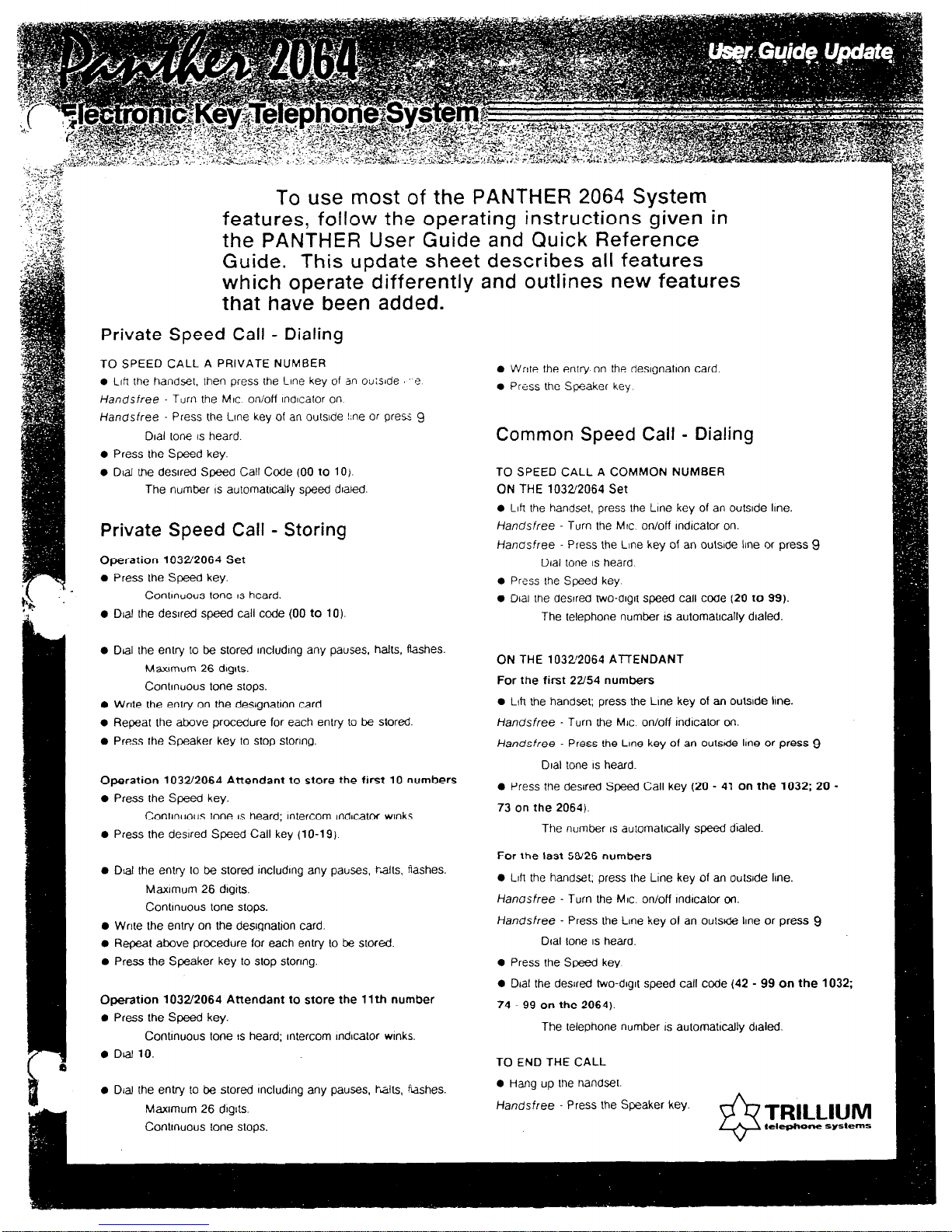
To use most of the PANTHER 2064 System
features, follow the operating instructions given in
the PANTHER User Guide and Quick Reference
Guide. This update sheet describes all features
which operate differently and outlines new features
that have been added.
Private Speed Call - Dialing
TO SPEED CALL A PRIVATE NUMBER
l
Llfi the handset, then press the Line key of an outsIde e
Handsfree Turn the MIC on/ofl lndlcator on.
Handsfree Press the Lme key of an outsIde !:ne or press 9
Dial tone IS heard.
l
Press the Speed key.
l
Dial Vie desired Speed Call Code (00 to 101.
The number IS automatically speed dlaIed.
Private Speed Call - Storing
Operation 1032’2064 Set
l
Press the Speed key.
Continuous tone IS heard.
l
Dial the desired speed call code (00 to 10).
l
Dlat the entry to be stored mcludlng any pauses, halls, Rashes.
MaxImum 26 dqts.
Contmuous tone stops.
l
Write the entry on the deslgnatjon card.
l
Repeat the above procedure for each entry to be stored
l
Press the Speaker key to stop storing.
Operation 103Z2064 Attendant to store the first 10 numbers
l
Press the Speed key.
Continuous tone IS heard; Intercom Indcator wrnks.
0
Press
the desired Speed Call key (10-19)
l
Dial the entry to be stored lncludlng any pauses, halts. flashes.
Maximum 26 dlgits.
Contmuous lone stops.
l
Write Ihe entry on the desgnation card.
l
Repeat above procedure for each entry (0 be stored.
l
Press the Speaker key to stop storing.
Operation 1032/2064 Attendant to store the 11th number
l
Press the Speed key.
Continuous tone IS heard; Intercom Indicator winks.
l
Dti 10.
l
Dial the entry to be stored mcludmg any pauses, l-al&, %shes.
Maximum 26 dIgits.
Continuous tone stops.
l
Write the entry on the deslgnatlon card
l
Press the Speaker key
Common Speed Call - Dialing
TO SPEED CALL A COMMON NUMBER
ON THE 1032/2064
Set
l
Llh the handset, press the Line key of an outslde line.
Handsfree Turn the MIC. on/off indtcator on.
Hanasfree Press the Line key of an outsbde line or pfess 9
Dial tone IS heard.
0 Press the Speed key.
0 Dial the desired two-dlglt speed call code (20 to 99).
The telephone number IS automatlcally dlaled.
ON THE 1032’2064 A-t-rENDANT
For the first 22/54 numbers
l
LI~I the handset; press the Line key of an outslde Ime.
Handsfree - Turn the MC. on/off indicator on.
Handsfree - Press the Lme key of an outs& line or press 9
Dial tone IS heard.
l
Press the desired Speed Call key (20 - 41 on the 1032; 20 -
73
on the 2064).
The number IS automallcally speed dialed
For the last 58126 numbers
0 Llh the handset; press the Lme key of an outside Ime.
Hanasfree - Turn the MIC. on/off lndlcator on.
Handsfree - Press the Line key of an outs&? line or press 9
Dial lone IS
heard.
0 Press the Speed key
0 Dlat the desired two-dlglt speed call code (42 - 99 on the
74 - 99 on the 2064).
The telephone number IS automattcally dialed.
TO END THE CALL
l
Hang up the nandset.
Handsfree Press the Speaker key.
Common Speed Call - Storing
l
Press the Speed key at slalion 10
Conr~nuous lone IS heard; ~nlercom mdlcator wmks.
. D,JI :W J~-WN 2-dIgIt speed Call COCK? (20-99)
Intercom Paging - To All Stations
TO PAGE ALL SETS SIMULTANEOUSLY
l
Lift the handset and press the Intercom key.
Handsfree Turn the MIC. on/off indtcator on.
l
Dial 80.
Double lone IS heard; Intercom lndlcalor wmks.
l
Make your announcemenr.
Zone Paging
TO PAGE A SPECIFIC ZONE
l
Llh me handset; press Ihe intercom key.
Handsfree - Turn the MIC. on/off Indicator on; press the Intercom key.
l
Dial rhe desired zone number (81 to 95).
Triple tone is heard; Intercom lndlcator wtnks.
l
Make your announcement.
TO PAGE ALL ZONES SIMULTANEOUSLY
l
Loft the handset and press the Intercom key.
Handsfree Turn the MIC. on/off lndlcator on; press the Intercom key.
l
Dial 80
Double tone IS heard; intercom indicator wmks.
l
Make your announcement.
Loudspeaker Paging
TOMAKEALOUDSPEAKERANNOUNCEMENT
0 Loft the handset; press the Intercom key.
Handsfree Turn the MIC. on/off indicator on; press the fntercom key.
Conanuous tone IS heard; intercom Indicator winks.
l
Dial 99.
A double tone burst IS heard.
l
Make your announcement
@
TRILLIUM
tek$eone sy*.ems
Specrhcabons and features are subject to change w/fhout notxe.
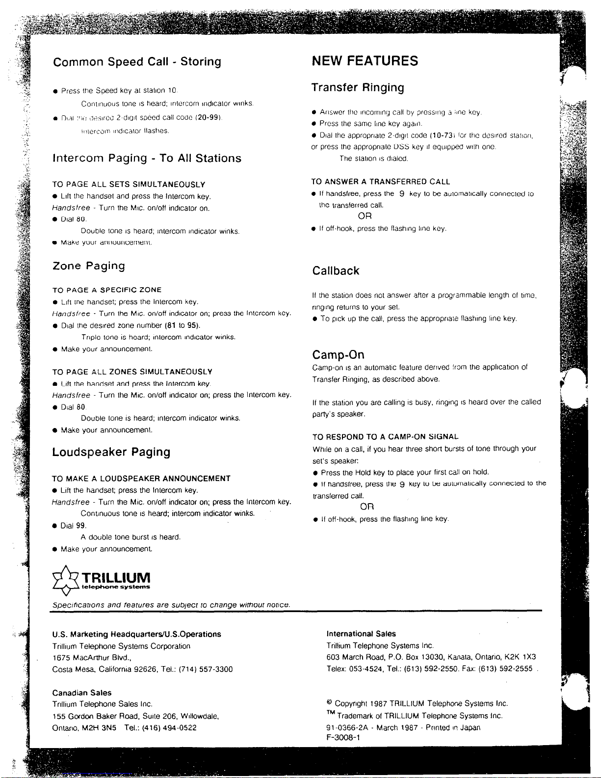
NEW FEATURES
Transfer Ringing
0 Answer lhc mcormng call by presstrlg a ;~ne key
0 Press Ihe same line key agafn
0 Dial the appropriate 2-dtgtt code (1 O-731 f;r Lhc desired stallon.
or press (he appropriate DSS key II equip@ wllh one
The station IS dlalcd.
TO ANSWER A TRANSFERRED CALL
0 If handsfree, press the 9 key to be aulomatlcally connected
iO
the transferred call.
OR
l
If off-hook, press the flashing lme key.
Callback
If the station does not answer after a programmable length of time.
nnglng returns to your set.
l
To pick up the call, press the appropriate flashmg lme key.
Camp-On
Camp-on IS an automatic feature derived from the application of
Transfer Rlngmg, as described above.
If the statlon you are callmg IS busy, nngmg IS heard over the called
party’s speaker.
TO RESPOND TO A CAMP-ON SIGNAL
While on a call, if you hear three short bursts of tone through your
set’s speaker:
l
Press the Hold key to place your first ca!l on hold.
l
If handsfree, press the 9 key to be aulomatlcalty connected to the
transferred call.
OR
l
If off-hook, press the flashmg line key.
U.S. Marketing Headquarte&U.S.Operations
Tnlllum Tetephone Systems Corporation
1675 MacArthur Blvd..
Costa Mesa. California 92626, Tel.: (714) 557-3300
Canadian Sales
Trrlllum Telephone Sales Inc.
155 Gordon Baker Road, Suite 206, WIllowdale,
Ontario. M2t-i 3N5 Tel.: (416) 4940522
International Sales
Triltlum Telephone Systems Inc.
603 March Road, P.O. Box 13030, Kanata. Onlarlo, K2K 1X3
Telex: 053-4524, Tel.: (613) 592-2550. Fax: (613) 592-2555
@ Copynghl 1987 TRILLIUM Telephm Systems Inc
TM Trademark of TRILLIUM Telephone Systems Inc.
91.0366-2A - March 1987 Printed (I! Japan
F-3008-1
Technical
Service
Manual., _
Technical
Spe.cifications
CONNECTORS
Equipment
CO or PBX lines 1 through 10 ........................ . ........
CO or PBX lines 11 through 20
..............................
Master KSU:
CO 1 TO 10.. .................................................
STATIONS 10 TO
i7 (to
station
wiring MDF) ....
STATIONS 18 TO 25 (to station wiring hlDF) ....
STATIONS 26 TO 33 (to station wiring MDF) ....
STATIONS 34 TO 41 (to station wiring MDF) ....
DOOR (to Door Answer Unit jack DA). ..............
POWER FAIL.. ........ I.. ...................................
PAGE (output - 200 mV rms into 600 Q)
.........
MUSIC (music input - 50 mV rms). .................
SMDR (to SMDR Unit)
...................................
Connectors 1 and 2 (used to connect
KSUs)
..........
EXTERNAL BATTERY
...................... ..- ...........
Ground
..........................................................
Expander KSU:
CO 11 TO 20 .................................................
STATIONS 42 TO 49 (to station wiring MDF) ....
STATIONS 50 TO 57 (to station wiring MDF) ....
’ STATIONS 58 TO 65 (to station wiring MDF)., . .
... STATIONS 66 TO 73 (to station wiring MDF) ... .
DOOR (to Door Answer Unit jack DA) ..;. ...... . .....
POWER FAIL (to 1st PowerFail Transfer Unit) ...
Connectors 1 and 2 (used to connect KSUs)
EXTERNAL BATTERY
..........
...................................
Ground
..........................................................
Station wiring MDF:
To station jacks.. .............................................
To dry contact interface
(2 A, maximum).
............
Panther 2064 Sets (to station jacks). ..........................
DSS/BLF Units (to station jacks). ............................
Door Module (to Door Answer Unit Dl and D2). .........
SMDR Unit:
To KSU connector SMDR.. ..............................
To printer, terminal, or personal
computer..
..........
JackslConnections Cable Pairs
50-pin RJ2lC.I . . . . . . . . . . . . . . . . . . . . . . . 25 (only 10 used)
50-pin RJ21C . . . . . . . . . . . . . . . . . . . . . . . . . 25 (only 10 used)
50-pin RJ21C . . . . . . . . . . . . . . . . . . . . . . . . 25
50-pin RJ2lC to 66-block . . . . . . . . . 25
50-pin RJ21C to 66-b&k . . . . . . . . . 25
50-pin RJ21C to 66-block . . . . . . . . . 25
50-pin RJ21C to 66-block . . . . . . . . . 25
Modular RJ25C . . . . . . . . . . . . . . . . . . . . . . . 3
Special connector . . . . . . . . . . . . . . . . . . . . . Not used
Mini-Jack l/8-inch, phono) 1
. . . . . . . .
Mini-Jack (l/8-inch, phono) . . . . . . . 1
Special
. . . . . . . . . . . . . . . . . . . . . . . . . . . . . . . . . . .
(See SMDR Unit)
Special
. . . . . . . . . . . . . . . . . . . . . . . . . . . . . . . . . . .
(See expander KSU)
Molex connector 1
. . . . . . . . . . . . . . . . . . . . . .
Screw terminal
. . . . . . . . . . . . . . . . . . . . . . . .
Single 12 AWG wire
50-pin RJ21C . . . . . . . . . . . . . . . . . . . . . . . .
50-pin RJ21C to 66-block . . . . . . . . .
50-pin RJ21C to 66-block...: . . . . .
50-pin RJ21C to 66-block . . . . . . . . .
5OSpin RJ2,lC to 66-block . . . . . . . . . ’
Modular RJ25C . . . . . . . . . . . . . . . . . . . . . . .
Special connector . . . . . . . . . . . . . . . . . . . . .
Special
. . . . . . . . . . . . . . . . . . . . . . . . . . . . . . . . . . . .
Special
. . . . . . . . . . . . . . . . . . . . . . . . . . . . . . . . . . . .
Screw terminal
. . . . . . . . . . . . . . . . . . . . . . .
25
25
25
$25
.
25
3
(See first Power Fail Transfer Unit)
Special (cables supplied)
1
Single 12 AWG wire
66-block to modular RJ14C.. ..... 2 each*
66-b&k to screw terminals.. ..... 1
Modular RJ14C (or RJ25C**) .... 2 each, cord supplied (or 3**)
Modular RJ14C.. ..................... 2 each, cord supplied
Screw terminals.. ..................... 1 for each module
Special.. ................................. Special (cable supplied)
DB-25.. .................................. RS-232 cable
* Length of each station cable should not exceed 2000 feet of 24 AWG; all station runs are star (home run) configurations
** Sets may alternatively use a 6-conductor modular cord-to-RJ25C jack (to gain access to the Set’s speaker terminals)
TRILLIUM
Telephone
Systems
Panther 2064
Page C-l
Technical
Service
Matiuql
Technical
Specific.ations
::i:: :::::::::: i ::::::::::::::::::::::::::::::::::::::::t ::::::::::: ::::: :::::::::::::::: ::::: i: ::::::::::::: ::::::::::::::::::::::::::::::::::::::::::::::::::::::::::::::::::::::::::~ . . . . . . . . . . . . . . . . . . . . . . . . . . . . . . . . . . . . . . . . . . . . . . . . . . . . . . . . . . . . . . . . . . . . . . . . . . . . . . . . . . ;...
. . . . . . . . . . . . . . . . . . . . . . . . . . . . . . . . . . . . . . . . . . . . . . . . . . . . . . . . . . . . . . . . . . . . . . . . ...” . . . . . . . . .
.
. .
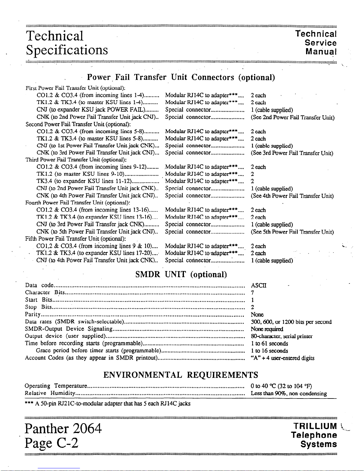
Power Fail Transfer Unit Connectors (optional)
Modular RJ14C to adapter***....
ModularRJ14C to adapter***....
Special connector . . . . . . . . . . . . . . . . . . . . .
Special connector . . . . . . . . . . . . . . . . . . . . .
First Power Fail Transfer Unit (optional):
C01.2 & C03.4 (from incoming lines l-4) . . . . . . . . . .
TK1.2 & TK3.4 (to master KSU lines 14) . . . . . . . . . .
CNJ (to expander KSU jack POWER FAIL) . . . . . . . . .
CNK (to 2nd Power Fail Transfer Unit jack CNJ)..
Second Power Fail Transfer Unit (optional):
C01.2 & C03.4 (from incoming lines 5-8) . . . . . . . . . .
TK1.2 & TK3.4 (to master KSU lines 5-8) ,.........
CNJ (to 1st Power Fail Transfer Unit. jack CNK)...
CNK (to 3rd Power Fail Transfer Unit jack CNJ)...
Third Power Fail Transfer Unit (optional):
C01.2 & C03.4 (from incoming lines 9-12) . . . . . . . .
TK1.2 (to master KSU lines 9-10) . . . . . . . . . . . . . . . . . . . . . .
TK3.4 (to expander KSU lines 1 l- 12) . . . . . . . . . . . . . . . . . .
CNJ (to 2nd Power Fail Transfer Unit jack CNK)..
CNK (to 4th Power Fail Transfer Unit jack CNJ)..
Fourth Power Fail Transfer Unit (optional):
C01.2 & C03.4 (from incoming lines 13-16)......
TK1.2 & TK3.4 (to expander KSU lines 13-16)....
CNJ (to 3rd Power Fail Transfer jack CNK) . . . . . . . . . .
CNK (to 5th Power Fail Transfer Unit jack CNJ)..
Fifth Power Fail Transfer Unit (optional):
CO,l:2 & C03.4 (from incoming lmes 9 & lo)....
. TK1.2 ‘& TK3.4 (to expander KSU lines 17-2Oj...:
CNJ (to 4th Power Fail Transfer Unit jack CNK)..
SMDR . UNIT (optional)
2each .
2each
1 (cable supplied)
(See 2nd Power Fail Transfer Unit)
Modular RJ14C to adapter***....
Modular RT14C to adapter***....
Special connector . . . . . . . . . . . . . . . . . . . . .
Special connector . . . . . . . . . . . . . . . . . . . . .
2each
2each
1 (cable supplied)
(See 3rd Power Fail Transfer Unit)
.Modular IU14C to adapteir**....
Modular IU14C to adapter***....
Modular RJ14C to adapter***....
Special connector . . . . . . . . . . . . . . . . . . . . .
Special connector . . . . . . . . . . . . . . . . . . . . .
2each
2
2
1 (cable supplied)
(See 4th Power Fail Transfer Unit)
Modular RJ14C to adapter***....
Modular RJ14C to adapter***....
Special connector . . . . . . . . . . . . . . . . . . . . .
Special connector . . . . . . . . . . . . . . . . . . . . .
2each
2each
1 (cable supplied)
(See 5th Power Fail Transfer Unit)
Mod&r RJ14C to adapter+**....
2d
ModaJar RJ14C toadapter’**....’
2each
Special connector . . . . . . . . . . . . . l....... 1 (cable supplied)
r.
Data code.. ............................................................................................................
Character Bits ........................................................................................................
Start Bits ..............................................................................................................
Stop Bits.. ............................................................................................................
Parity ..................................................................................................................
Data rates (SMDR switch-selectable) .........................................................................
SMDR-Output Device Signaling ..............................................................................
Output device (user supplied).
...................................................................................
Time before recording
starts (programmable). ..............................................................
Grace period before
timer starts (programmable). ....................................................
Account Codes (as they appear in SMDR printout)
.......................................................
ASCII 7
1
2
None
300,600, or 1200 bits per second
None required
8Ocharacter, serial printer
lto6lseconds
1 to 16 seconds
“A” + 4 user-entered digits
ENVIRONMENTAL REQUIREMENTS
Operating Temperature.. ..........................................................................................
0 to 40 “C (32 to 104 “F)
Relative Humidity .................................................................................................. Less than 90%. noncondensing
*** A 50-pin RJILlC-to-modular adapter that has 5 each RJ14C jacks
Panther 2064
’ Page C-.2
TRILLIUM [,
Telephone
Systems
Technical
Service ,
Technical-
Manual
Specifications
. . . . . . . . . . . . . . . . . . . . . . . . . . . . . .
::::::::::::::::::::::::::::::::::::::::::::::::~:::::::~:::::::::::::::::::::::::::::::::::::::::::;:::::::::::::::::::::::::;:::::::::::::::::::::::::::::::::::::::::::::::::::::
::::::: :::::::;:::::::::::
:::::::::::::::::
:,~ :::::::;
::::::::
,. . . . . . . . . .,.... . . . . . . . . . . . . . . .
.
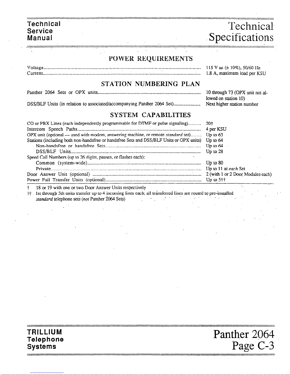
PO.WER REQUIREMENTS
Voltage . . .._.....................................................................................................,.....
115 V ac (k lo%), SO/60 Hz
Current . . . . . . . . . . . . . . . . . . . . . . . . . . . . . . . . . . . . . . . . . . . . . . . . . . . . . . . . l.....; . . . . . . . . . . . . . . , . . . . . . . . . . . . . . . . . . . . . . . . . . . . . . .‘...
1.8 A, maximnm load per KSU
STATION NUMBERING PLAN
Panther 2064 Sets or OPX units . . . . . . . . . . . . . . . . . . . . . . . . . . . . . . . . . . . . . . . . . . . . . . . . . . . . . . . . . . . . . . . . . . . . . . . . . . . . . . . 10 through 73 (OPX unit not al-
lowed on station 10)
DSS/BLF Units (in relation to associated/accompanying Panther 2064 Set) . . . . . . . . . . . . . . . . . . . . . . Next higher station number
SYSTEM CAPABILITIES
CO or PBX Lines (each independently programmable for DTMF or pulse signaling)
...........
Intercom Speech Paths.. ........................................................ . .................................
OPX unit (optional - used with modem, answering machine, or remote sru.r&rd set)
.........
Stations (including both non-handsfree or handsfree Sets and DSS/BLF Units or OPX units)
Non-handsfree or handsfree Sets.. ........................................................................
DSS/BLF Units
..............................................................................................
Speed call Numbers (up to 26 digits, pauses, or flashes each):
Common (system-wide).
............................. . .....................................................
Private ...........................................................................................................
Door Answer Unit (optional)
...................................................................................
Power Fail Transfer Units (optional).
.........................................................................
20t
4 per KSU
Up to 63
up to 64
up to 64
Up to 28
Up to 80
Up to 11 at each Set
2 (with 1 or 2 Door Modules each)
UP to 5tt
t 18 or 19 with one or two Door Ansyer Units
respedvely
-_
??
1st
through 5th units transfer up to 4 incoming lines each: all knsferred lines are routedto
pre-$sdld
I B
standard
telephone setk(nqiPanther 2064 Sets)
- :
’ * I
.
I.
TRILLIUM
Telephone
Systems
Technical
Service
Manual
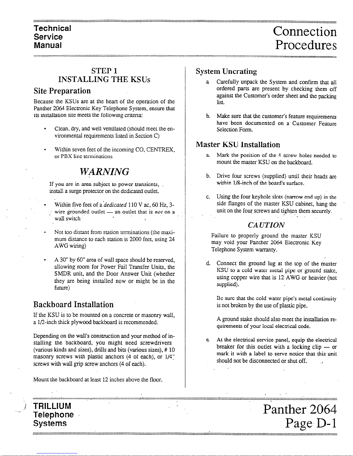
STEP 1
INSTALLING THE KSUs
Site Preparation
Because the KSUs are at the heart of the operation of the
Panther 2064 Electronic Key Telephone System, ensure that
its installation site meets the following criteria:
.
Clean, dry, and well ventilated (should meet the environmental requirements listed in Section C)
.
Within seven feet of the incoming CO, CENTREX,
or PBX line terminations
WARNING
If you are in area subject to power transients,
install a surge protector on the dedicated outlet.
.
Within
five
feet of
ahedicated
110 V ac, 60 Hz, 3-
-’ wire grounded outlet - an outlet that is not on a
wall switch ,-
.
Not too distant from station terminations (the maxi-
mum distance to each station is 2000 feet, using 24
AWG wiring)
.
A 30” by 60” area of wall space should be reserved,
allowing room for Power Fail Transfer Units, the
SMDR unit, and the Door Answer Unit (whether
they are being installed now or might be in the
future)
Backboard Installation
If the KSU is to be mounted on a concrete or masonry wall,
a l/2-inch thick plywood backboard is recommended.
Depending on the wall’s construction and your method of in-
stalling the backboard, you might need screwdrivers
(various kinds and sizes), drills and bits (various sizes), # 10
masonry screws with plastic anchors (4 of each), or l/4:
screws with wall grip screw anchors (4 of each).
Mount the backboard at least 12 inches above the floor.
Connection
Procedures
:::::
System Uncrating
a Carefully unpack the System and confirm that all
ordered parts are present by checking them off
against the Customer’s order sheet and the packing
list.
h
Make sure that the customer’s feature requirements
have been documented on a Customer Feature
Selection Form.
Master KSU Installation
a
Mark the position of the 4 screw holes needed to
mount the master KSU on the backboard.
b.
Drive four screws (supplied) until their heads are
within l/&inch of the board’s surface.
c.
Using the four keyhole slots (narrow end up) in the
side flanges of the master KSU cabinet, hang the
unit on the four screws and tighten them securely.
.
CAUTION
Failure to properly ground the master KSU
may void your Panther 2064 Electronic Key
Telephone System warranty.
d Connect the ground lug at the top of the master
KSU to a cold water metal pipe or ground stake,
using copper wire that is 12 AWG or heavier (not
supplied).
Be sure that the cold water pipe’s metal continuity
is not broken by the use of plastic pipe.
A ground stake should also meet the installation requirements of your local electrical code.
e At the electrical service panel, equip the electrical
breaker for this outlet with a locking clip - or
mark it with a label to serve notice that this unit
should not be disconnected or shut off.
,
. . . . . . . . . . . . . . . . . . . . . . . . . . . . . . . . . . . . . . . . . . . . . . . . . . . . . . . . . . . . . . . . . . . . . . . . . . . : . . . . . . . . . . . . . . . . . . . ..-................................. - . . . . . . . . . . . . . . . . . . . . . . . . . . . ......’ .......................................................................... : ...............................
. . . . . . . . . . . . . . . . . . . . . . . . . . . . . . . . . . . . . . . . . . . . . . . . . . . . Y . . . . . . . . . . . . . . . . . . . . . . . . . . . . . . . . . . . . . . . . . . . . . . . . . . . . . . . , . . . . . . . . . . . . . . . .....................................................................................................................................................
I
__ ,b .TRlLLlUM
Telephone .
Systems
.
Panther 2064
Page. D- 1
U
Connection
Procedures’
Technical
Service
Manual
Expander KSU Installation
a Fit the mounting bracket (supplied with the expand-
er KSU) over the master KSU, aligning the top of
the mounting bracket with the top of the master
KSU.
b. Mount the expander KSU on the mounting bracket
using the 4 screws supplied with the expander
KSU.
CAUTION
Failure to properly ground the expander KSU
may void your Panther 2064 Electronic Key
Telephone System warranty. .
c. Connect the ground lug at the top of the expander
KSU to a cold water metal pipe or ground stake,
using ,copper wire that is 12 AWG or heavier (not
supplied).
$ ’
Be sure that the cold. water -pipe’s metal’continuit~
is not broken by the use of plastic pipe,
A ground stake should also meet the installation requirements of your local electrical code.
E At the electrical service panel, equip the electrical
breaker for this outlet with a locking clip - or
mark it with a label to serve notice that this unit
should not be disconnected or shut off.
g Install the two special cables supplied with the ex-
pander KSU between connectors 1 and 2 at the
bottom of the expander KSU and connectors 1 and
2 at the bottom of the master KSU.
2. If optional Power Fail Transfer Units are to
be installed, follow the instructionsin Step 12
to connect the incoming lines.
3. If one optional Door Answer Unit is to be
installed, line 10 must be left vacant; if a.second optional Door Answer Unit is to be
installed line.20 must be left vacant.
4. See also the Typical System Layout
Diagrams on pages E- 1 and E-2.
Plug the 50-pin RI21 connector for lines l-10 into the 50-
pin connector on the right side of the master KSU labeled
CO 1 TO CO10 and the 50-pin RI21 connector for lines 1 l20 into the 50-pin connector on the right side of the expander KSU labeled CO1 1 TO CO20. Secure the KSU end of the
cables with the screws and plastic tie-wraps provided with
the units.
On the other hand, if the incoming lines are not terminated
in 50-pin RI21 connectors, wire them into two 66-blocks
(with female 25-pin connectors).
Then, install two 25-pair cable - with male 50-pin connec-
tors at both ends - between the 66-blocks’s 50-pin
connector and the master and expander KSU 50-pin connectors, labeled CO 1 TO 10 and CO11 TO 20, respectively.
Secure the KSU end of the cables with the screws and plastic tiewraps provided with the units.
See the incoming line wiring table that starts on the facing
page for details.
. .
STEP 2
CONNECTING
INCOMING TELEPHONE LINES
WARNING
Do not plug in the master and expander KSU
power cords until instructed to do so in Step 4.
NOTES
1. If the incoming telephone lines are not yet
installed, ask the telco that they be terminated
in two 50-pin RI21 connector, one for lines l-
10 and the other for lines 1 l-20.
TRIL’LIUM
Telephone
Systems
Technical
Service
Manual
Connection
Procedures
Incoming Line
I
Circuit 66-Block
SO-Pin 25 Pair
Number
Function Terminal
Connector Cable*
1
2
voice (tip)
1 26
white/blue
voice (ring)
2 1 blue/white
voice (tip) 3
27 white/orange
voice (ring)
4 2
orange/white
3
4
voice (tip)
5 28 white/green
voice (ring) 6
3
green/white
voice (tip)
7 29 white/brown
voice (ring)
8 4
brown/white
5
‘6
voice (tip) 9
voice (ring)
10
voice (tip)
11
voice (ring)
12
30
white/slate
5 slate/white
31
red/blue
6 blue/red
7
8
voice (tip)
.voice (ring)
voice (tip)
voice (ring)
13 32 red/orange
14; * .._ ‘7
orange/red I
15
33 - red/green
16 8
green/red
9
10
voice (tip)
voice (ring)
voice (tip)
voice (ring)
17
18
19
20
34
red/brown
9 brown/red
.
35
red/slate
io
slate/red
* The first color listed is the predominant color;
the second color listed is the track or stripe color.
Incoming Line Wiring Table (Lines 1 through ‘10)
TRILLIUM
-’ Telephone
Systems
Panther $064
Page D-3
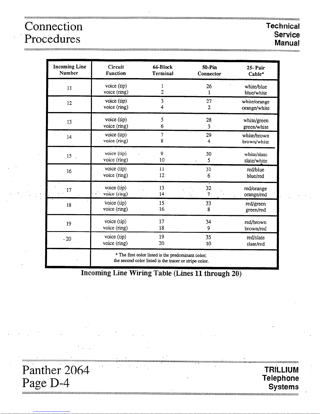
Connection
Procedures
Technical
Service
Manual
Incoming Line Circuit 66-Block
50-Pin
25 Pair
Number Function Terminal
Connector
Cable*
11
12
voice (tip) 1 26
voice (ring) 2 1
voice (tip) 3
27
voice (ring) 4 2
white/blue
blue/white
white/orange
orange/white
13
14
voice (tip) 5 28 white/green
voice (ring) 6 3 green/white
voice (tip)
7 29 white/brown
voice (ring) 8 4
brown/white
15 voice (tip)
9 30 white/slate
voice (ring)
10
5
slate/white
16 voice (tip) 11
31 red/blue
voice (ring) 12
6
blue/red
-17 voice (tip) 13 :
32 red/orange
’ .’
I -. voice (ring)
14 7. ‘, orange/red
18 voice (tip) 15
33 red/green
voice (ring) 16
8 green/red
19 voice (tip) 17
34 red/brown
voice (ring)
18 9 brown/red
20 voice (tip)
19
-
35 red/slate
voice (ring)
20 10
slate/red
* The first color listed is the predominant color,
the second color listed is the tracer or stripe color.
Incomirig Line Wiring Table (Lines 11 through 20)
p&her 2()&J ‘. .. . ‘.
Page D-4
TRliLlUM
Telephone
Systems
.................................................................................................................................................................................
. .
................................................................................................................................................................................................................................................................................
..............................................................................................

. . . . . . . . . . . . . . . . . . . . . . . . . . . . . . . . . . . . . . . . . . . . . . . . . . . . . . . . . . . . . . . . . . . . . . . . . . . . . . . . . . . . . . . . . . . . _ . . . . . . . . . . . . . . . . . . . . . . . . . . . . . ..............................................
. . . . . . . . . . . . . . . . . . . . . . . . . . . . . . . . . . . . . . . . . . . . . . . . . . . . . . . . . . . . . . . . . . . . . . . . . . . . . . . . . . . . . . . . . . . . . . . . . . . . . . . . . . . . . . . . . . . . . . . . . . . . . . . . . . . . . . . . . . . . . . . . . . . . . . . . . . . . . . . . . . . . . . . ,
......................................................................................................... ..............................................................
~~. ------..-- . . . . . . . . . . . . . . . . . . .
I.. ......................
Technical
Service
Connection
Manual
Procedures
. . . . . . . . . . . . . . . . . . . . . . . . . . . . . . . . . . . . . . . . . . . . . . . . . . . . . . . . . . . . . . . . . . . . . . . . . . . . . . . . . . . . . . . . . . . . . . . . . . . . . . . . . . . . . . . . . . . . . . . . . . . . . . . . . . . . . . . . . . . . . . . , . . . . . . . . . . . . . . . . . . . . . . . . . . . . . . . . . . . . . . _. _ . . . . . . . . .
. . . . . . . . . . . . . . . . . . . . . . . . . . . . . . . . . . . . . . . . . . . . . . . . . . . . . . . . . . . . . . . . . . . . . . . . . . . . . . . . . . . . . . . . . . . . . . . . . . . . . . . . . . . . . . . . . . . . . . . . ............................................................................ :::::::::::::::::::::::::::::::::::::::::: :::::::::::::::::::::::::::::::::::
.
.* -.
[This page intentionally left blank]
. .
. . . . . . . . . . . . .._...... . . . . . . . . . . . . . .
. . . . . . . . . . - . . . . . . . . . . . . . . . . . . . . . . . . . . . . . . . . . . . . . . . . . . . . . . . . . . . . . . . . . . . . . . . . . . . . . . . . . . . . . . . . . . . . . . . . . ..-a . . . . . . . . . . . . . . . . . . . . . . . . . . . . . . . . . . . . . . . . . . . . . . . . . . . . . . . . . . . . . . . . . . . . . . . . . . . . . . ....................... : _.........._.............. :: ..........._....._...........
....... . . . . . . . . . . . . . . . . . . . . . . . . . . . . . . . . . . . . . . . . . . . . . . . . . . . . . . . . . . . . . . . . . . . . . . . . . . . . . . . . . . . . . . . . . . . . . . . . . . . . . . . . . . . . . . . . . . . . . . . . . . . . ...................... : ............................................. Iy ....................,
...........: ..........,
.TRILLIUM
\
Telephone
Panther 2064’
Systems
Page D-5
.................................... I..
v
.....................................................................................................................................................................
..............................................................................................................................
::::::::::::::::::::::: ::::::::::::::::::::::::::::::::::::::::::::::::::::::::::::::::::::: : :::::::::::::::
Connection
Procedures
Technical
Service
Manual
. . . . . . . . . . . . . . . . . . . . . . . . . . . . . . . . . . . . . . . . . . . . . . . . :.: . . . . . :..: . . . . . . . . . . . . . . . . . . . . . . . . . . . . . . . . . . . . . . . . . . . . . . . . . . . . . . . . . . . . . . . . . . . . .
...............................................................................................................................................
. . . . . . . . . . . . . . . . . . . . . . . . . . . . . . . . . . . . . . . . . . . . . . . . . . . . . . . . . . . . . . . . . . . . . . . . . . . . . . . . . . . . . . . . . . . . . . . . . . . . . . . . . . . . . . . . . . . . . . . . . . . . . . . . . . . . . . . . . . . . . . . . . . . . . . . . . . . . . . . . . . . . . . . . . . . . . . . . . . . . . . . . . . . . . . . . . . . . . . . . . . . . . . . . . . . . . . . . . . . . . . . . . . . . . . . . . . . . . . . . . . . . . . . . . . . . ..... ...... . ... ,
STEP 3
INSTALLING STATION WIRING
WARNING
To prevent damage to the KSUs while wiring,
make sure that the KSU power cords are not
plugged in. Do not apply power to the KSUs
until instructed to do so in Step 4.
NOTES
1. Because much of the feature programming is
performed from station 10, choose a convenient or strategic location for station 10.
2. DSS/BLF Units require their own station
.wiring jack - and the station number of the
DSS/BLF Unit must be the next higher number
when compared to the station number of the
accompanying Set.
’
.
For example, if the Marketing Department’s
secretary was to be given a DSS/BLF unit, two
consecutively numbered station wiring jacks
- say station 62 and station 63 - would have
to be installed at the secretary’s desk.
To continue the example, the secretary’s Set
would be connected to station 62 - and the
accompanying DSS/BLF Unit would be connected to station 63.
a Decide on the location and station number (from 10
up through 73) for each Set.
NOTE
If an external amplifier is to be used at any of
the station locations, mount a 6-conductor
RI25 jack at the station location. See Step 13.
h Mount a 4-conductor RI14 jack within 6 feet of the
desired Set location at each station.
c. On the backboard, mount four split 66-blocks with
a female 50-pin connector provided for each half
(left and right).
d. Install eight 25-pair cables - with male 50-pin
connectors at both ends - between the 66-block’s
50-pin connectors and the master KSU 50-pin connectors labeled STATIONS 10 TO 17.LOUD
BELL, 18 TO 25,26 TO 33, and 34 TO 41 and the
expander KSY 50-pin connectors labeled .’
.STATIONS 42 TO 4950 TO 57,58 TO 65, and 66
TO 73.
NOTE
See the table on the following eight pages for
wiring details for each group of eight stations.
Also, refer to the Typical System Layout
Diagrams on pages E-l and E-2.
e For each station, install a length (not to exceed
2000 feet) of 4-conductor, 24 AWG cable from the
66-block terminals to the station wiring jack.
Panther .2064.
Page D-6
TRILLIUM
Telephone
Systems
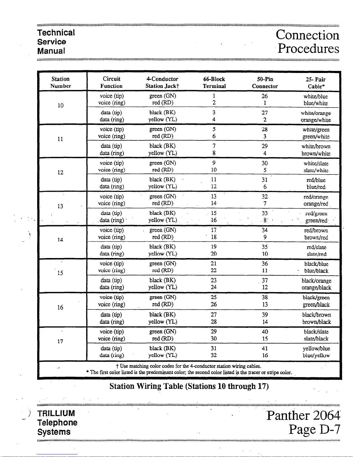
. -.
Technical
Service
Manual
Connection
Procedures
Station Circuit QConductor 66-Block SO-F%l
25- Pair
Number Function Station Jackt Terminal
Connector Cable’
voice (tip)
green (GN)
1 26
white/blue
10
voice (ring)
red P>
2
1 blue/white
data (tip)
black (BK) 3
27
white/orange
data b-&J)
yellow (YL) 4
2
orange/white
voice (tip)
green GN)
5
28 white/green
11
voice (ring)
red (RD)
6 3
green/white
data (tip)
black (BK) 7
29 white/brown
data (fig)
yellow (YL) 8
4
brown/white
voice (tip)
green GN)
9
30 white/slate
12
voice (ring)
red VW
10
5 slate/white
data (tip>
black@K) 11
31
red/blue
data b-i%)
yellow (YL) 12
6
blue/red
voice (tip)
green(GN) 1.3
32 red/orange
13
voice (ring)
rd(RD)
14.
7 orange/red
data (tip)
black(BK)
13
33 red/green
:
data (ring)
yellow W-1 ,
I6 . ‘, .8:*
.’ gef&&. 1’
voice (tip) &en (GN) 17’
34
red/brown
14
voice (ring)
red cm.
’ 18 9
brown/red
data (tip)
black (EIK) 19
35
lZd/Sht.f?
data b-i%> Yellow W-)
20
10
Slat&d
voice (tip)
green WI
21
36
black/blue
15
voice (ring)
red CR-W
22 11 . blue/black
ha (tip) black (BK) 23
37 black/orange
data (fig)
yellow W-1
24
12 orange/black
voice (tip)
green GN)
25 38 bl&/green
16
voice (ring)
red WI
26 13
green/black
data @PI
black @K)
27 39 black/brown
data b-4)
yeflow WA
28 14 brown/black
voice (tip)
green (WI
29 40 black/slate
17
voice. (ring)
=d@-W
30 15 slate/black
data (tip>
black (BK) 31 41
yellow/blue
data w%> yellow W-1
32
16 blue/yellow
.I
t U&e matching color codes for the 4-conductor station wiring cables.
* The first color listed is the predominant color, the second color listed i+ the pacer or stripe color.
Station Wiring Table (Stations 10 through 17)
j TRILLIUM
- Telephone
Systems
‘Panther.2064
Page D-7
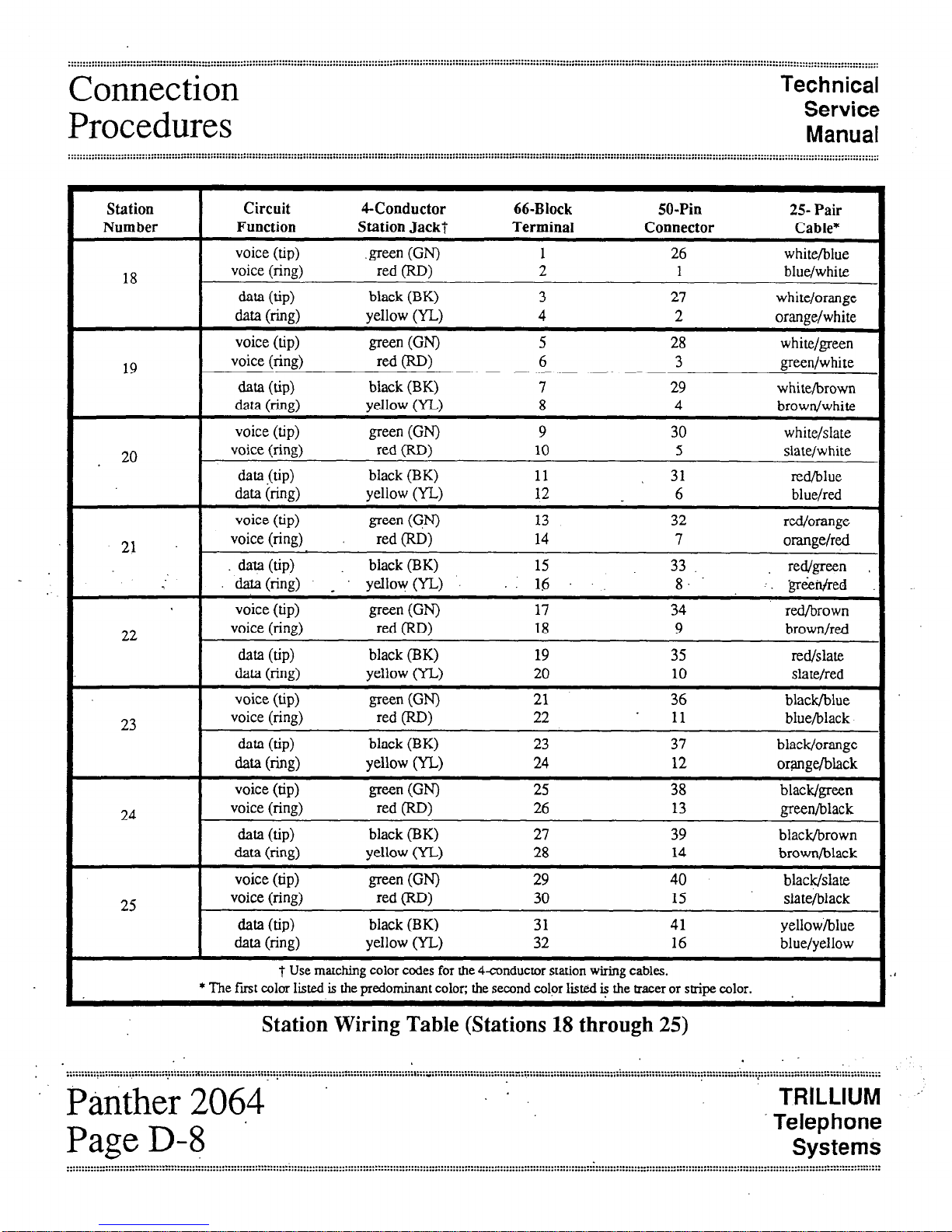
Connection
Procedures
Technical
Service
Manual
Station
Circuit CConductor 66-Block 50-Pin
25 Pair
Number
Function Station Jacki Terminal Connector
Cable*
voice (tip)
.green (WI
1 26 white/blue
18
voice (ring)
red (RD>
2
1
blue/white
data (tip)
black (BK)
3 21 white/orange
data b-hi9
yellow (YL)
4 2
orange/white
voice (tip)
green WI
5 28 white/green
19
voice (ring)
red W>
6 3 green/white
data (tip)
black (BK) 7 29
white/brown
data b-hi9
yellow (YL) 8 4
brown/white
voice (tip)
green (WI
9 30 white/slate
. 20
voice (ring)
red (RD)
10 5 slate/white
dm (tip>
black (BK) 11 I 31 red/blue
data (ring) yellow (YL) 12 6 blue/red
voice (tip)
green WI
13 32 red/orange
21
voice (ring) red (RD) 14 7 orange/red
data (tip)
black (BK) 15
33 red/green ,
daf” (ring) _ yellovv (YL) 16 8.
.‘. ‘gr&&d
voice (tip)
green GW
17 34 reillbrown
22
voice (ring)
red (RD)
18 9 brown/red
data (tip)
black (BK) 19 35 red/slate
data (ring) yellow (YL) 20 10 slate/red
voice (tip)
green (WI
21 36 black/blue
23
voice (ring)
red (RD)
22 11 blue/black
data (tip)
black (BK)
23 37 black/orange
data b-w
yellow (YL) 24
12
orange/black
voice (tip)
green GW
25 38 black/green
24
voice (ring)
red (RD>
26 13 green/black
data (tip) black (BK) 27 39 black/brown
data (ring) yellow (YL)
28
14 brown/black
voice (tip)
green (0
29
black/slate
25
voice (ring)
red CRD)
30
4o
15 slate/black
data (tip)
black (BK) 31 41 yellow/blue
data (ring) yellow (YL)
32
16
blue/yellow
t Use matching color codes for the 4-conductor station wiring cables.
* The first color listed is the predominant color; the second color listed e the tracer or stripe color.
Station Wiring Table (Stations 18 through 25)
.
. . . . . . . . . . . . . . . . . . . . . . . . . . . . . . . . . . . . . . . . . . . . x.; ::::;:::::y:::: y.p:y *::::::::::::::::: :‘.:::y::;:::: :‘.:::: ::*y.; ::::::y::: ye::’ .:::::: :‘/:: T*yy *:::::::::::::::: :‘.::::::::: ::::::::::::::: :::::::::: :: :::::::::::::::::::: i: :::::: :::-;: :‘.:::::::::::::::::::::::::
. . . . . . . . . . . . . . . . . . . . . . . . . . . . . . . . . . . . . . . . . . . . .
” P&tither 2064
TRILLIUM -’
Page D-8 ’
Telephone
Systems
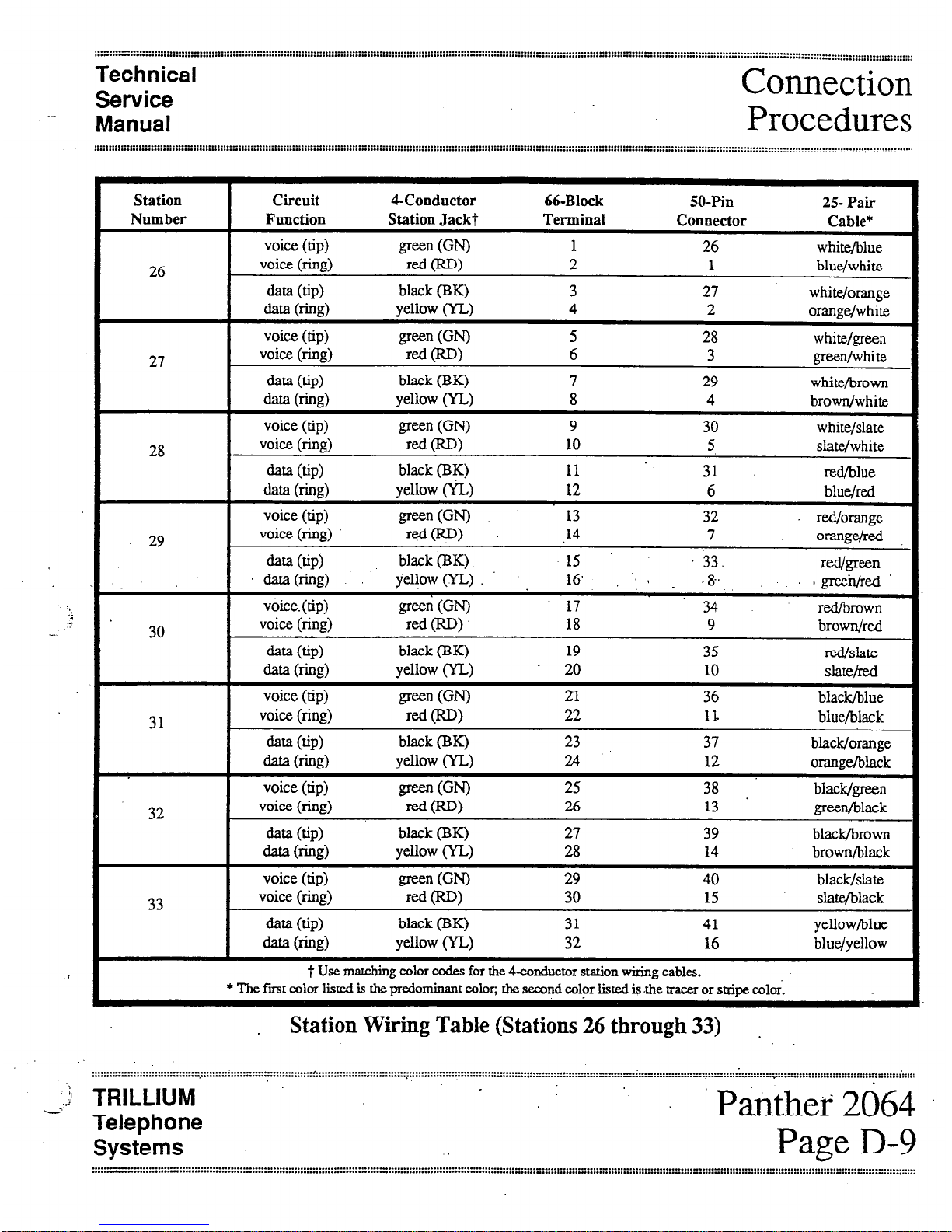
-.
Technical
Service
Manual
Connection
Procedures
Station
Number
26
27
28
29
30
31
32
33
Circuit CConductor 66-Block SO-Pin
25- Pair
Function Station Jack? Terminal
Connector Cable*
voice (tip)
green GW
1 26 white/blue
voice (ring)
red CRD)
2 1 blue/white
data (tip)
black (BK)
3 27
white/orange
data b-%)
yellow (YL) 4 2
orange/white
voice (tip)
green GN)
5
28 white/green
voice (ring)
red W>
6
3 green/white
data (tip>
black (BK) 7
29
white/brown
data b-h3>
yellow (YL) 8 4
brown/white
voice (tip)
green (WI
9 30
white/slate
voice (ring)
red P-W
10 5
slate/white
data (tip)
black @T() 11
31 red/blue
data b-w
yellow (YLJ 12
6 blue/red
voice (tip)
green(GN)
13
32 red/orange
voice (ring)
r&p)
.14
7
~~ge/red
data (tip)
black (BK)
15 33.
data(ring) .’
Wgreen
yeliow (YL) .
16, -: 9
.&
;gree$&
voice. (tip)
green(W
17
34 red/brown
voice (ring)
rd(RD)*
18 9
brown/red
data (tip)
black (BK) 19 35
l-d/Slate
data (l-Q>
yellow (YL) ’ 20 10
SlZlt&Xl
voice (tip)
green GN)
21
36
black/blue
voice (ring)
red CRD)
22 II.
blue/black
data (tip) bh& (BK)
23 37 black/orange
data ww) yellow 0
24 12
orange/black
voice (tip)
green (0
25 38 black/green
voice (ring)
d(RD),
26 13 green/black
data (bP>
black (BK) 27 39 black/brown
data wx) Wow WI
28 14 brown/black
voice (tip)
green GN)
29 40 black/slate
voice (ring)
reti (RD)
30 15 slate/black
data (tip)
black (BK)
31 41 yellow/blue
data b-&z> Wow WA
32 16 blue/yellow
t Use matching color codes for the
4-conductrx station wiring cables.
* The fmt color listed is the predo
minant color, the second color listed is .the tracer or stripe colors
-
Station Wiring Table (Stations 26 through 33) .
_.: TRILLIUM
Telephone
Systems
Pitithef 2064
Page D-9
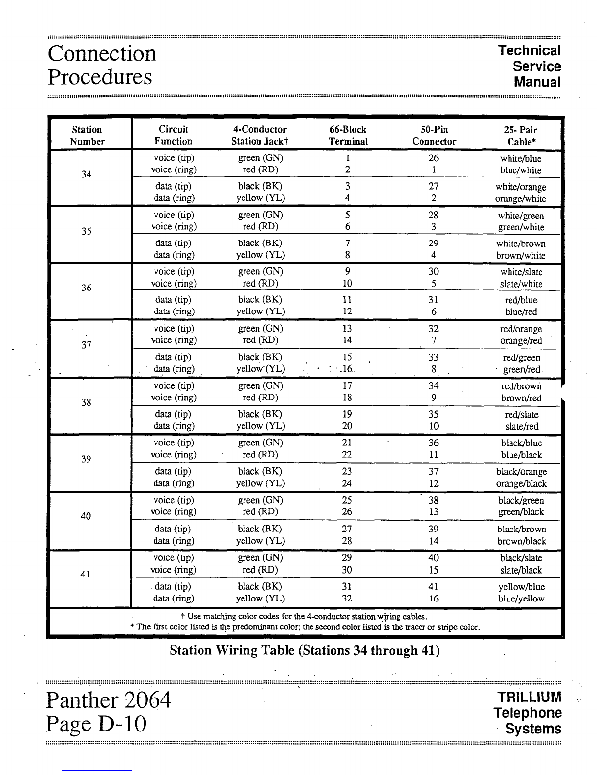
Connection
Procedures
Technical
Service
Manual
Station
Number
34
35
36
37
38
39
40
41
Circuit CConductor 66-Block 50-Pin
25-
Pair
Function Station Jack? Terminal Connector
Cable*
voice (tip)
green 00
1
26 white/blue
voice (ring)
red 0)
2 1
blue/white
data (tip) black (BK) 3 27
white/orange
clata b-w
yellow (YL) 4 2
orange/white
voice (tip)
green (GN)
5
28 white/green
voice (ring)
red @W
6
3 green/white
data WP>
black (BK)
7 29 white/brown
data (ring) yellow (YL) 8 4
brown/white
voice (tip)
green (0
9
30 white/slate
voice (ring) red (RD) 10
5 slate/white
data (tip)
black (BK) 11
31 red/blue
data (ring) yellow (YL) 12 6
blue/red
voice (tip)
green (0
13 32
red/orange
voice (ring)
red W>
14 7 orange/red
data (tip)
black, (BK) 15 33
I
red/green
*b b-hi9
yellow-(YL) .‘, + : .-16.. . 8
green/red
voice (tip)
green GN)
17 34 r&browh
voice (ring) red (RD)
18 9 brown/red
data (tip) black (BK) 19
35 red/slate
data (ring) yellow (YL) 20
10 slate/red
voice (tip)
green VW
21 . 36
black/blue
voice (ring) .
red VW
22 .
11 blue/black
data (up)
black (BK) 23 37 black/orange
data b-&d
yellow (YL) . 24 12
orange/black
voice (tip)
green GN)
25 38 black/green
voice (ring)
red (RD)
26 13 green/black
data (tip) black (BK) 27 39 black/brown
data (ring) yellow (YL) 28 14 brown/black
voice (tip)
green VW
29
40 black/slate
voice (ring)
red CRD)
30 15 slate/black
data (tip) black (BK)
31 41 yellow/blue
data 0-w
yellow (YL)
32 16 blue/yellow
t Use matching color codes for the 4-conductor station w+ing cables.
* The first color listed is t&e predominant color; the second color listed is the tracer or stxipe color.
Station Wiring Table (Stations 34 through 41)
.
Panther 2064
‘.
TRI’LLIUM
Page D-10
Telephone
Systems
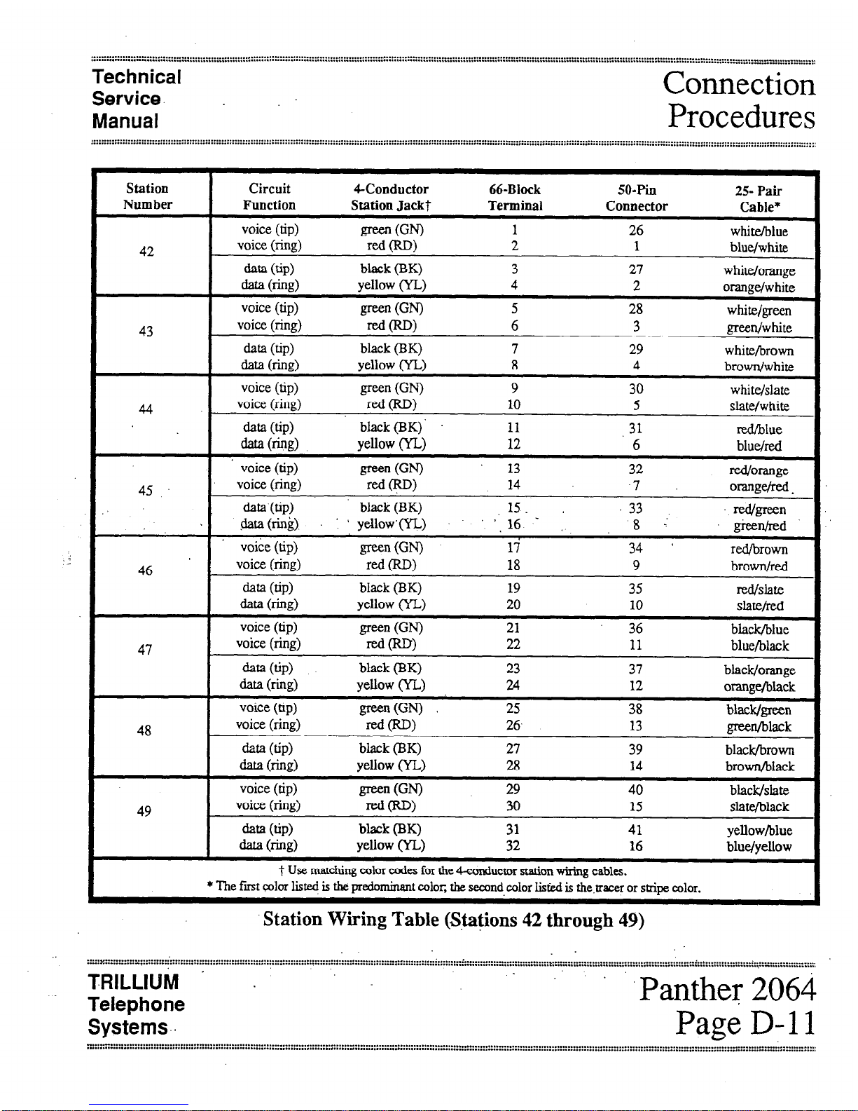
Technical
Service. .
Manual
Connection
Procedures
Station Circuit CConductor 66-Block SO-Pill
25- Pair
Number Function Station Jackt Terminal Connector
Cable*
voice (tip)
green (W
1 26
white/blue
42
voice (ring)
red W)
2 1
blue/white
data (tip)
black (BK) 3 27
white/orange
data 0-e)
yellow (YL) 4 2
orange/white
voice (tip)
green (0
5 28
white/green
43
voice (ring)
=d(RD)
6 3
green/white
data (up)
black (BK) 7 29
white/brown
data b-b9
yellow (YL) 8
4
browu/white
voice (tip)
green WI
9
30 white/slate
44 ‘.
voice (ring)
red WI
10 5
slate/white
data (up)
black(BK)‘ 11
.31
red/blue
data NW>
yellow (YL) 12
6 blue/red
voice (tip)
green (0 13
32
red/Or;mge
45
voice (ring)
red (RD)
14 -7
o=wzw.
data (tip)
black (BK) 15 33
.&ita (rink). : ’ yebow’ ‘; 16 -
red/green
8 :
‘greenfred’
voice (tip)
green K-W
17
34 ( red/brown
46 ’ ,
voice (ring)
red W>
18
9 brown/red
ma (tip)
black (BK) 19 35
red/slate
data 6-w
yellow (YL) 20
10
Shte/Ed
voice (tip)
green GN)
21 36
black/blue
47
voice (ring)
=d(RD)
22 11
blue/black
data (tip)
black (BK)
23 37 black/orange
data W-G) Now W-1
24 12
orange/black
voice (tip)
green(GN)
25 38 black/green
48
voice (ring)
fit-W
26. 13
green/black
data (tip)
black (BK) 27 39 black5rown
data mvs)
yellow (YL) 28 14 brown/black
voice (tip)
green GN)
29 40 black/slate
49
voice (ring)
=-dcRD)
30
15
slate/black
data (up)
black (BK) 31 41 yellow/blue
data w-43) Yellow Co
32
16 blue/yellow
t Use matching color codes for the 4-conductor station wiring cables.
* The fmt c&r listed is the predemimnt color, the second color listed is the.uacer or stripe color.
Station Wiring Table (Stations 42 through 49)
.
..... y.. ....................
“I., ......... ..”
i..
.................................................................................................
. ......... .
................................
......................................................................................................................................................... >
.....................................................
. .................... i ........................
...............................................................................
”
..................
TRILLIUM . .
Telephone
Systems..
Panther 2064
Page D-l 1
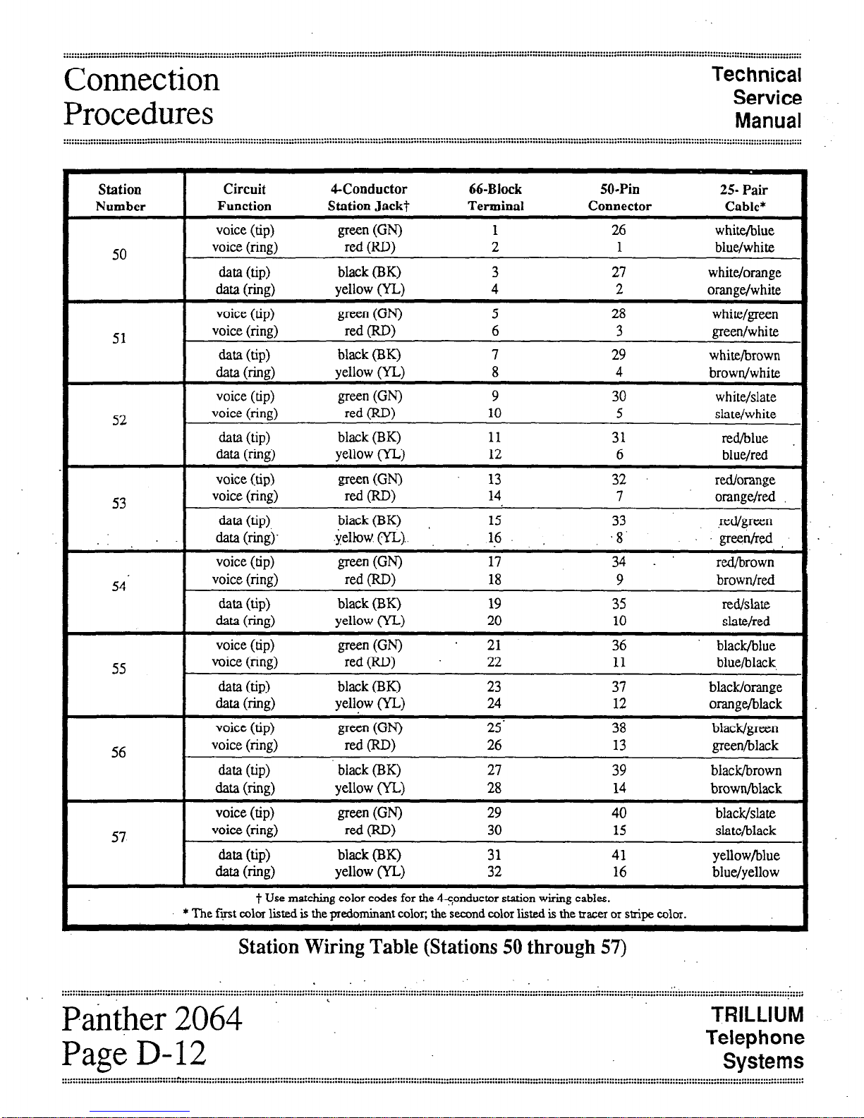
Connection
Procedures
Technical
Service
Manual
Station
I
Circuit 4-Conductor 66-Block 50-Pin
25- Pair
Number
Function Station Jack? Terminal Connector
Cable*
50
51
voice (tip)
green
GN) 1 26 white/blue
voice (ring) red WI 2 1 blue/white
data (tip) black (BK) 3 27 white/orange
data (l-e) yellow (YL) 4 2 orange/white
voice (tip)
green
WI 5 28 white/green
voice (ring) red OW 6 3 green/white
data (tip) black (BK) 7 29 white/brown
data bx> yellow (YL) 8 4 browdwhite
I
voice (tip)
green WI
white/slate
52 voice (ring) red (RD> 10 5
data (tip) black (BK) 11 31
data (e=T> yellow (YL) 12 6
slate/white
red/blue
blue/red
voice (tip) green(GN) 13 32 red/orange
53
voice (ring)
rf2.d (RD>
14
7
orange/red
data (tip).
black (BK) 15 33 ~edlg-reen
.
data (ring)~
.yelkW (YL).. ‘,
16. .8’
greetid,
voice (tip)
green VW
17 34. .
red/brown
54’
voice (ring)
red 0)
18 9 brown/red
data (tip)
black (BK) 19 35
IWifSlate
aa b-a9
yellow (YL)
20 10 slate/red
55
voice (tip) green(GN) 21
36 black/blue
voice (ring) red(RD) 22 11 blue/black,
data @PI
black (BK) 23 37 black/orange
data 6-h) yellow (YL) 24 12 orange/black
56
voice (tip)
green GN)
25’ 38 black/green
voice (ring) red (RD) 26 13 green/black
data (tip) black (BK) 27 39 black/brown
data w%) yellow (YL) 28 14 brown/black
57
voice (tip)
green
GN) 29 40 black/slate
voice (ring) red (RD) 30 15 slate/black
data (tip) black (BK) 31 41 yellow/blue
data (l-i%) yellow (YL) 32 16 blue/yellow
t Use matching color codes for the 4cpnductor station wiring cables.
* The frost color listed is the predominant color; the second color liited is the tracer or stir color.
Station Wiring Table (Stations 50 through 57)
:::;::::-::::::: :: ::::::::-::::::: :” . . . . . . . . . . . . . . . . . . . . . . . . . . . . . . . . . . . . . . . . . . . . . . . . . . . . . . . . . . . . . . . . . . . . . . . . . . . . . . . . . . . . . . . . . . . . . . . . . . . . . . . . . . . . . . . . . . . . . . . . ....................................................................................-........... _ ...._...........
I
. . . . . . . . . . , . . . . . . . . . . . . . . . . . . . . . . . . . . . . . . . . . . . . . . . . . . . . . . . . . . . . . * . . . . . . . . . . . . . . . . . . . . . . . . . . . . . . . . . . . . . . . . . . . . . . . . . . . . . . . . . . . ..................................................~..............................................................
Pa&her 2064 ‘.
TRILLIUM
Page D-12
Telephone
Systems
 Loading...