

Page 1

SkyPilot™ by Trilliant® Gateway Pro
Installation and Setup
SP-5XXX
Preliminary
| i
671-00XXX-01 Rev A Draft 1
Page 2

© 2012 Trilliant, Inc. All rights reserved
This publication, or parts thereof, may not be reproduced in any form, by any method, for any purpose.
Product specifications are subject to change without notice. This material is provided for informational purposes only; Trilliant assumes no
liability related to its use and expressly disclaims any implied warranties of merchantability or fitness for any particular purpose.
Trilliant Trademarks
Trilliant™, CellReader®, CellGateway™, SecureMesh™, SerViewCom®, UnitySuite™, SkyPilot®, SyncMesh™, the Trilliant logo, and the SkyPilot logo are
trademarks of Trilliant Incorporated and/or its subsidiaries.
All other trademarks are the property of their respective owners.
This material is provided for informational purposes only; Trilliant assumes no liability related to its use and expressly disclaims any implied warranties of
merchantability or fitness for any particular purpose.
All specifications, descriptions, and information contained herein are subject to change without prior notice.
Third-Party Trademarks
Java and all Java-based trademarks and logos are trademarks or registered trademarks of Sun Microsystems, Inc. in the United States and other
countries.
MySQL is a registered trademark of MySQL AB in the United States, the European Union, and other countries.
All other designated trademarks, trade names, logos, and brands are the property of their respective owners.
Third-Party Software Program Credits
This product includes software developed by the Apache Software Foundation (http://www.apache.org/), licensed under the Apache License.
This product includes the DHCP Server software from Internet Systems Consortium, licensed under the DHCP License. The DHCP Server software is
copyright © 2004 Internet Systems Consortium, Inc. (“ISC”). Copyright © 1995–2003 Internet Software Consortium. All rights reserved. Redistribution and
use in source and binary forms, with or without modification, are permitted provided that the following conditions are met: 1. Redistributions of source
code must retain the above copyright notice, this list of conditions and the following disclaimer. 2. Redistributions in binary form must reproduce the
above copyright notice, this list of conditions and the following disclaimer in the documentation and/or other materials provided with the distribution.
3. Neither the name of ISC, ISC DHCP, nor the names of its contributors may be used to endorse or promote products derived from this software without
specific prior written permission. THIS SOFTWARE IS PROVIDED BY INTERNET SYSTEMS CONSORTIUM AND CONTRIBUTORS “AS IS” AND ANY EXPRESS OR
IMPLIED WARRANTIES, INCLUDING, BUT NOT LIMITED TO, THE IMPLIED WARRANTIES OF MERCHANTABILITY AND FITNESS FOR A PARTICULAR PURPOSE
ARE DISCLAIMED. IN NO EVENT SHALL ISC OR CONTRIBUTORS BE LIABLE FOR ANY DIRECT, INDIRECT, INCIDENTAL, SPECIAL, EXEMPLARY, OR
CONSEQUENTIAL DAMAGES (INCLUDING, BUT NOT LIMITED TO, PROCUREMENT OF SUBSTITUTE GOODS OR SERVICES; LOSS OF USE, DATA, OR PROFITS;
OR BUSINESS INTERRUPTION) HOWEVER CAUSED AND ON ANY THEORY OF LIABILITY, WHETHER IN CONTRACT, STRICT LIABILITY, OR TORT (INCLUDING
NEGLIGENCE OR OTHERWISE) ARISING IN ANY WAY OUT OF THE USE OF THIS SOFTWARE, EVEN IF ADVISED OF THE POSSIBILITY OF SUCH DAMAGE.
This product includes the FTP Server software from vsftpd (
This product includes Java software from Sun Microsystems, licensed under Sun Microsystems' Binary Code License Agreement. Copyright 2003, Sun
Microsystems, Inc. All rights reserved. Use is subject to license terms. Sun, Sun Microsystems, the Sun logo, Solaris, Java, the Java Coffee Cup logo, J2SE,
and all trademarks and logos based on Java are trademarks or registered trademarks of Sun Microsystems, Inc. in the U.S. and other countries.
This product includes JBOSS Version 3.2.3 software from JBoss, licensed under the GNU Lesser General Public License. Some bundled products in JBOSS
are licensed under the Apache License.
This product contains Java Telnet Application (JTA 2.0).
This product contains the MibBrowser software from Mibble.
This product includes software the copyright of which is owned by and licensed from MySQLAB.
This product includes software developed by the OpenSSL Project for use in the OpenSSL Toolkit. (
The OpenSSL Project. All rights reserved. Redistribution and use in source and binary forms, with or without modification, are permitted provided that
the following conditions are met: 1. Redistributions of source code must retain the above copyright notice, this list of conditions and the following
disclaimer. 2. Redistributions in binary form must reproduce the above copyright notice, this list of conditions and the following disclaimer in the
documentation and/or other materials provided with the distribution. 3. All advertising materials mentioning features or use of this software must
display the following acknowledgment: “This product includes software developed by the OpenSSL Project for use in the OpenSSL Toolkit.
http://www.openssl.org/)” 4. The names “OpenSSL Toolkit” and “OpenSSL Project” must not be used to endorse or promote products derived from this
(
software without prior written permission. For written permission, please contact [email protected]. 5. Products derived from this software may
not be called “OpenSSL” nor may “OpenSSL” appear in their names without prior written permission of the OpenSSL Project. 6. Redistributions of any
form whatsoever must retain the following acknowledgment: “This product includes software developed by the OpenSSL Project for use in the
OpenSSL Toolkit (http://www.openssl.org/)”. THIS SOFTWARE IS PROVIDED BY THE OpenSSL PROJECT ``AS IS'' AND ANY EXPRESSED OR IMPLIED
WARRANTIES, INCLUDING, BUT NOT LIMITED TO, THE IMPLIED WARRANTIES OF MERCHANTABILITY AND FITNESS FOR A PARTICULAR PURPOSE ARE
DISCLAIMED. IN NO EVENT SHALL THE OpenSSL PROJECT OR ITS CONTRIBUTORS BE LIABLE FOR ANY DIRECT, INDIRECT, INCIDENTAL, SPECIAL,
EXEMPLARY, OR CONSEQUENTIAL DAMAGES (INCLUDING, BUT NOT LIMITED TO, PROCUREMENT OF SUBSTITUTE GOODS OR SERVICES; LOSS OF USE,
DATA, OR PROFITS; OR BUSINESS INTERRUPTION) HOWEVER CAUSED AND ON ANY THEORY OF LIABILITY, WHETHER IN CONTRACT, STRICT LIABILITY, OR
TORT (INCLUDING NEGLIGENCE OR OTHERWISE) ARISING IN ANY WAY OUT OF THE USE OF THIS SOFTWARE, EVEN IF ADVISED OF THE POSSIBILITY OF
SUCH DAMAGE.
This product includes libraries developed by Eric Young and is licensed under the Original SSLeay License. This product includes cryptographic software
written by Eric Young (
[email protected]). All rights reserved. Redistribution and use in source and binary forms, with or without modification, are permitted provided
Young (
that the following conditions are met: 1. Redistributions of source code must retain the copyright notice, this list of conditions and the following
disclaimer. 2. Redistributions in binary form must reproduce the above copyright notice, this list of conditions and the following disclaimer in the
documentation and/or other materials provided with the distribution. 3. All advertising materials mentioning features or use of this software must
display the following acknowledgement: “This product includes cryptographic software written by Eric Young (
'cryptographic' can be left out if the routines from the library being used are not cryptographic related :-). 4. If you include any Windows specific code (or
a derivative thereof) from the apps directory (application code) you must include an acknowledgement: “This product includes software written by Tim
[email protected])”. THIS SOFTWARE IS PROVIDED BY ERIC YOUNG ``AS IS'' AND ANY EXPRESS OR IMPLIED WARRANTIES, INCLUDING, BUT NOT
Hudson (
LIMITED TO, THE IMPLIED WARRANTIES OF MERCHANTABILITY AND FITNESS FOR A PARTICULAR PURPOSE ARE DISCLAIMED. IN NO EVENT SHALL THE
AUTHOR OR CONTRIBUTORS BE LIABLE FOR ANY DIRECT, INDIRECT, INCIDENTAL, SPECIAL, EXEMPLARY, OR CONSEQUENTIAL DAMAGES (INCLUDING, BUT
NOT LIMITED TO, PROCUREMENT OF SUBSTITUTE GOODS OR SERVICES; LOSS OF USE, DATA, OR PROFITS; OR BUSINESS INTERRUPTION) HOWEVER
CAUSED AND ON ANY THEORY OF LIABILITY, WHETHER IN CONTRACT, STRICT LIABILITY, OR TORT (INCLUDING NEGLIGENCE OR OTHERWISE) ARISING IN
ANY WAY OUT OF THE USE OF THIS SOFTWARE, EVEN IF ADVISED OF THE POSSIBILITY OF SUCH DAMAGE.
This product includes SNMP software from WestHawk, licensed under the WestHawk License.
This product includes JFreeCharts from
This product includes JasperReports from http://jasperreports.sourceforge.net/index.html, licensed under GNU Lesser Public License.
[email protected]). This product includes software written by Tim Hudson ([email protected]). Copyright (C) 1995–1998 Eric
http://www.jfree.org/, licensed under GNU Lesser General Public License.
http://vsftpd.beasts.org/), licensed under the GNU General Public License.
http://www.openssl.org/). Copyright (c) 1998–2005
[email protected])” The word
ii |
Page 3

Contents
About This Guide . . . . . . . . . . . . . . . . . . . . . . . . . . . . . . . . . . . . v
Audience and Purpose . . . . . . . . . . . . . . . . . . . . . . . . . . . . . vi
How This Guide Is Organized . . . . . . . . . . . . . . . . . . . . . . . . . vi
Conventions Used in This Guide . . . . . . . . . . . . . . . . . . . . . . .vii
Chapter 1 Introduction . . . . . . . . . . . . . . . . . . . . . . . . . . . . . 1
Solution Overview . . . . . . . . . . . . . . . . . . . . . . . . . . . . . . . . 2
Mesh Network . . . . . . . . . . . . . . . . . . . . . . . . . . . . . . . . . . . 2
SkyPilot Gateway & SkyPilot Gateway Pro . . . . . . . . . . . . . . . . . 4
SkyPilot Extender, Extender DualBand . . . . . . . . . . . . . . . . . . . 4
SkyPilot Connector . . . . . . . . . . . . . . . . . . . . . . . . . . . . . . . . 5
Chapter 2 Your SkyPilot Gateway Pro Kit . . . . . . . . . . . . . . . . . . 7
Kit Contents . . . . . . . . . . . . . . . . . . . . . . . . . . . . . . . . . . . . 8
Required Tools and Supplies. . . . . . . . . . . . . . . . . . . . . . . . . . 9
Chapter 3 Planning Your SkyPilot Network . . . . . . . . . . . . . . . 11
Deployment Process Overview . . . . . . . . . . . . . . . . . . . . . . . 12
Network Planning . . . . . . . . . . . . . . . . . . . . . . . . . . . . . . . 12
Co-Located SkyPilot Gateway Pro Devices . . . . . . . . . . . . . . . . 16
Chapter 4 Configuring the SkyPilot Gateway Pro. . . . . . . . . . . . 17
Provisioning . . . . . . . . . . . . . . . . . . . . . . . . . . . . . . . . . . . 17
Cabling . . . . . . . . . . . . . . . . . . . . . . . . . . . . . . . . . . . . . . 18
Powering Up. . . . . . . . . . . . . . . . . . . . . . . . . . . . . . . . . . . 21
Configuring the SkyPilot Gateway Pro. . . . . . . . . . . . . . . . . . . 22
Configuring Adjacent SkyPilot Gateway Pros . . . . . . . . . . . . . . 26
Chapter 5 Installing the SkyPilot Gateway Pro . . . . . . . . . . . . . 27
Install Devices . . . . . . . . . . . . . . . . . . . . . . . . . . . . . . . . . . 27
Mounting . . . . . . . . . . . . . . . . . . . . . . . . . . . . . . . . . . . . . 28
Chapter 6 Verifying Connectivity . . . . . . . . . . . . . . . . . . . . . . 33
Confirming SkyPilot Gateway Pro Connectivity . . . . . . . . . . . . . 33
Confirming SkyPilot Extender and SkyPilot Connector Connectivity 35
Confirming SkyPilot Extender DualBand Access Point Connectivity 37
Troubleshooting . . . . . . . . . . . . . . . . . . . . . . . . . . . . . . . . 39
Appendix A Grounding Guidelines . . . . . . . . . . . . . . . . . . . . . . 41
General Grounding Strategy . . . . . . . . . . . . . . . . . . . . . . . . . 41
Adding Surge Protection . . . . . . . . . . . . . . . . . . . . . . . . . . . 43
Grounding Checklist . . . . . . . . . . . . . . . . . . . . . . . . . . . . . . 43
Appendix B FCC Statements . . . . . . . . . . . . . . . . . . . . . . . . . . 45
FCC Class A Notice . . . . . . . . . . . . . . . . . . . . . . . . . . . . . . . 45
FCC Class B Notice . . . . . . . . . . . . . . . . . . . . . . . . . . . . . . . 45
Maximum Permissible Exposure . . . . . . . . . . . . . . . . . . . . . . 46
FCC 15.203 statement . . . . . . . . . . . . . . . . . . . . . . . . . . . . . 46
Contents | iii
Page 4

Regulatory Statements for Canada . . . . . . . . . . . . . . . . . . . . . 46
Appendix C Specifications . . . . . . . . . . . . . . . . . . . . . . . . . . . .49
Appendix D Pinouts. . . . . . . . . . . . . . . . . . . . . . . . . . . . . . . . .53
RJ-45 Pins . . . . . . . . . . . . . . . . . . . . . . . . . . . . . . . . . . . . . 53
DB-9 Adapter . . . . . . . . . . . . . . . . . . . . . . . . . . . . . . . . . . . 54
iv | Contents
Page 5

About This Guide
This guide explains how to install and set up a SkyPilot™ Gateway™ Pro device. It
assumes administrator-level knowledge of IP networks and a familiarity with
configuring wireless devices.
Chapter Highlights
Audience and purpose
How this guide is organized
Conventions used in this guide
| v
Page 6

Audience and Purpose
This guide provides directions for installing and setting up a SkyPilot Gateway Pro.
This guide assumes administrator-level knowledge of IP networks and a familiarity
with configuring wireless devices.
How This Guide Is Organized
This guide is organized as follows:
Chapter 1, “Introduction,” provides an overview of the SkyPilot solution,
describes the SkyPilot devices, and then illustrates how they combine to form
a mesh network.
Chapter 2, “Your SkyPilot Gateway Pro Kit,” provides the information you need
before you begin your installation.
Chapter 3,“Planning Your SkyPilot Network,” provides an overview of network
planning guidelines and procedures
Chapter 4, “Configuring the SkyPilot Gateway Pro,” describes the process for
bringing up a SkyPilot Gateway Pro unit for the first time.
Chapter 5, “Installing the SkyPilot Gateway Pro,” explains how to mount the
unit in the field.
Chapter 6, “Verifying Connectivity,”describes the steps needed to verify proper
operation of each device.
Appendix A, “Grounding Guidelines,” provides direction on protecting your
SkyPilot device with proper grounding and surge protection.
Appendix B, “FCC Statements,” provides the FCC radio frequency interference
statements for the SkyPilot Gateway Pro devices.
Appendix C, “Specifications,” give the mechanical and electrical specifications
of the SkyPilot Gateway Pro.
Appendix D, “Pinouts,” provides pinouts for connectors and adapters to
connect to the Ethernet interface port labeled “CPE” on the SkyPilot Gateway
Pro power supply and the device’s serial interface.
vi | About This Guide
Page 7

Conventions Used in This Guide
This section describes the text and syntax conventions used throughout this
guide.
Text Conventions
This guide uses the following text conventions:
Italic is used to introduce new terms.
Bold is used to indicate what you click or type in a graphical user interface (for
example, commands names or text being entered). In examples showing user
interaction with the command-line interface, bold is used to indicate user
input as opposed to command output.
A monospace font is used for code elements (variable names, data values,
function names, and so forth), command lines, scripts, and source code
listings.
Italic-monospace is used for replaceable elements and placeholders
within code listings.
Syntax Conventions
This guide uses the following conventions when showing syntax:
Angle brackets, “<“ and “>”, enclose mandatory elements. You must enter
these elements. For example:
ping <IP-address>
Square brackets, “[“ and “]”, enclose optional elements. You can omit these
elements. For example:
show filter [filter-table-number]
Square brackets are also used to show the current value of parameters in the
output of some commands.
A vertical bar, “|”, separates choices. For example:
show bridge [cache | port]
Conventions Used in This Guide | vii
Page 8

viii | About This Guide
Page 9

Introduction
This chapter provides an overview of the SkyPilot Networks solution, describes the
SkyPilot devices, and then illustrates how they combine to form a mesh network.
Chapter Highlights
Solution Overview
Mesh Network
SkyPilot Gateway and SkyPilot Gateway Pro
1
| 1
Page 10

Solution Overview
A SkyPilot Network delivers a wireless, end-to-end broadband solution that
seamlessly supports high-capacity, high-coverage mesh networks. Designed for
managed-access networks and service providers, the SkyPilot network takes
broadband wireless the “last mile” with a cost-effective, robust infrastructure
solution.
Based on a high-performance architecture that includes intelligent antenna arrays,
the SkyPilot network delivers a dynamic broadband solution.
SkyPilot wireless devices are simple to install and easily fit into any type of wireless
environment—metropolitan, business, or home.
The auto-discovery and rapid provisioning features of a SkyPilot wireless mesh
network can greatly reduce deployment and maintenance costs. Multiple
topology options and network scalability create intriguing options for rapidly
expanding a metro Wi-Fi customer base.
Mesh Network
The typical configuration for a SkyPilot network is a mesh topology, which uses
SkyPilot Extenders to extend range and add network flexibility. In a mesh
configuration, subscribers can either connect directly to the SkyPilot Gateway Pro
or connect indirectly via SkyPilot Extenders (see Figure 1-1). In addition to adding
range, a mesh network allows connections from locations where obstructions
prevent line-of-sight access to a SkyPilot Gateway Pro.
Mesh networks are ideal for dense subscriber environments, for filling in coverage
“holes,” and for reaching subscribers in areas where RF communication is
obstructed by hills, trees, buildings, or other obstacles.
2 | Chapter 1 Introduction
Page 11
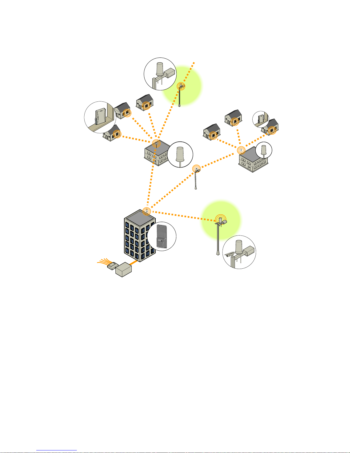
Figure 1-1. SkyPilot wireless mesh network
r
SkyPilot Extender
SkyPilot Connector
SkyPilot Connectors link subscribers
to the wireless mesh network via
an Ethernet port that allows
connection from a PC or a local
area network.
SkyPilot Gateway Pro
SkyPilot Extender
Adds a Wi-Fi access point providing
802.11 wireless access to the mesh
network in metropolitan “hot”
zones.
Wi-Fi zone
SkyPilot Extender
SkyPilot Extender
SkyPilot Extenders increase the
coverage footprint by extending
the wireless mesh network
beyond the range of the
SkyPilot Gateway Pro.
SkyPilot Connecto
SkyPilot Extender
Provides broadband Internet access
via Wi-Fi and supports public
safey applications such as video
surveillance.
.
Internet
Mesh Network | 3
Page 12

SkyPilot Gateway & SkyPilot Gateway Pro
The SkyPilot Gateway and Gateway Pro operate as a base stations for a wireless
mesh network. They provide an interface between the wired infrastructure and a
wireless network of subscribers who enjoy secure, high-speed access to the
Internet.
A SkyPilot wireless network requires at least one SkyPilot Gateway or SkyPilot
GatewayPro, for operation. If necessary, you can add additional SkyPilot Gateway
Pros to increase network capacity or provide redundancy.
A SkyPilot Gateway or Gateway Pro resides at a location with easy access to wired
infrastructure—usually a POP (point of presence) or data center.
The SkyPilot Gateway Pro uses an advanced, second-generation electronically
steerable antenna to deliver higher overall throughput. In addition, it XXX...
SkyPilot Extender, Extender DualBand
SkyPilot Extenders and SkyPilot Extender DualBands provide a cost-effective way
to extend range and balance network loads by operating as repeaters to extend
the wireless range of a SkyPilot Gateway Pro (see Figure 1-1). You can add a
SkyPilot Extender device to your network to expand your coverage footprint and
provide redundancy through SkyPilot’s mesh networking features. SkyPilot
Extender devices, including DualBands, can provide subscribers with a direct
connection to the wireless network via the device’s Ethernet port.
SkyPilot Extender DualBand is a dual-radio solution that combines SkyPilot’s long-
range, high-capacity 5 GHz mesh backhaul with a high-powered 2.4 GHz
802.11b/g access point that allows service providers and municipalities to offer
standard Wi-Fi services, for targeted hot zones or ubiquitous coverage patterns.
For optimum performance, install the SkyPilot Extender in an elevated location
such as a roof, tower, or utility pole.
4 | Chapter 1 Introduction
Page 13

SkyPilot Connector
SkyPilot Connectors link your subscribers to the SkyPilot wireless network. An
Ethernet port on the device allows a connection to a subscriber’s computer, or to
a local area network (LAN) via a data switch or router. Designed for installation by
the service provider, the SkyPilot Connector attaches to an external structure such
as an eave, roof, or pole.
The SkyPilot Connector DualBand offers the same features as a SkyPilot Connector,
plus a Wi-Fi access point that enables service providers and municipalities to
provide standard 802.11 wireless access, for targeted hot zones, or for dense
coverage patterns.
SkyPilot Connector | 5
Page 14

6 | Chapter 1 Introduction
Page 15

Your SkyPilot Gateway Pro Kit
Your SkyPilot Gateway Pro kit provides the basic equipment you need to install the
device and configure it for operation on a SkyPilot wireless mesh network. This
chapter describes that equipment and lists additional items you should have on
hand before starting installation.
Chapter Highlights
Kit Contents
Required Tools and Supplies
2
| 7
Page 16

Kit Contents
The contents of the SkyPilot Gateway Pro kit are listed below:
SkyPilot Gateway Pro unit
Power supply. This unit is both a power supply and a power injector. Your
SkyPilot Gateway Pro is powered over Ethernet, and you may use either the
included power supply or your own PoE PSE equipment. Note that the power
supply is not outdoor-ratedl it should be mounted indoors or in a suitable
enclosure.
DB-9 to RJ-45 adapter. This can be used to adapt the cat-5 serial port cable to a
DB-9 serial port.
GPS antenna
GPS antenna mounting bracket
Weatherproof cable connector housing
Mounting hardware, consisting of:
two sets of two-piece pole clamps
double-hinged mounting bracket
single-hinged mounting bracket
Nuts, bolts, and washers
8 | Chapter 2 Your SkyPilot Gateway Pro Kit
Page 17
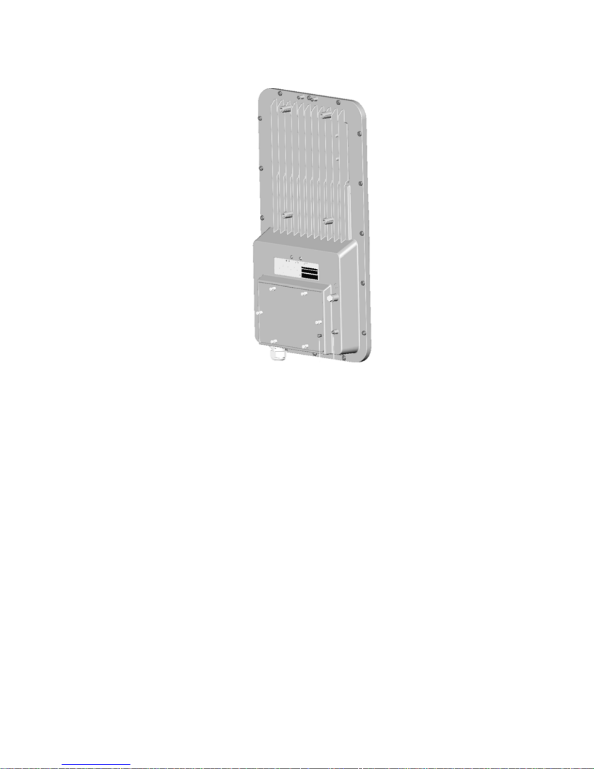
Figure 2-1. SkyPilot Gateway Pro (rear view)
Required Tools and Supplies
Before starting installation, you also need the following:
For basic mounting:
7/16" wrench
9/16” wrench
Phillips screwdriver
Loc-tite or other thread-locking compound
For pole mounting:
Magnetic level
Steel pole between 1 1/4" and 2 1/8" in diameter
For network cabling:
Spool of CAT-5 shielded network cable, outdoor-rated.
RJ-45 straight through cable for a serial connection to a console (standard
CAT-5 patch cable will work)
Required Tools and Supplies | 9
Page 18

NOTEIn theory, you should never need to service a unit once it is
deployed. However, should you need to do so, access to the serial
port may be required. Many installers find it prudent to run a
serial cable from the SkyPilot to a location that gives easier access.
Crossover cable (for connecting to a an access point, switch, or router)
RJ-45 unshielded connectors (connectors without a protective plastic
boot are preferred; they fit through the cable clamp more easily.)
RJ-45 crimping tool
Open-end wrench, adjustable or 1-3/6” (30 mm)
Surge protection device (strongly recommended)
For configuration:
Computer with a serial port, a terminal emulation program, a network
interface card, and a Web browser. A laptop recommended for
convenience.
10 | Chapter 2 Your SkyPilot Gateway Pro Kit
Page 19

Planning Your SkyPilot Network
This chapter provides instructions for configuring the SkyPilot Gateway Pro and
then performing the physical installation.
Chapter Highlights
Planning your installation
GPS and the SkyPilot Gateway Pro
3
| 11
Page 20

Deployment Process Overview
Table 3-1 summarizes the stages of SkyPilot network planning and deployment.
Table 3-1. Stages of deployment
Stage Description
Identify equipment
locations
Choose an operating
frequency
Provision SkyPilot devices Choose a provisioning mode for the devices: manual
Install SkyPilot devices Install the devices, beginning with SkyPilot Gateway
Verify connectivity Confirm that the SkyPilot Gateway Pro is online.
Identify and prepare locations for installation.
Choose a “clean” center frequency that permits
interference-free operation of devices.
or automatic.
Provision the devices. (For automatic provisioning,
install operating system and SkyPilot EMS software.)
Pro devices and building out.
Confirm that installed SkyPilot Connectors and
SkyPilot Extenders have established a link with the
SkyPilot Gateway Pro.
Review link characteristics and network performance.
Network Planning
Identify Equipment Locations
Deployment of a SkyPilot network starts with a site survey to help you identify the
devices you need and choose optimum locations for installation.
Identifying locations for the SkyPilot Gateway Pro and SkyPilot Connectors is
straightforward. For the SkyPilot Gateway Pro, location depends on proximity to
existing network infrastructure and site elevation. SkyPilot Connectors are placed
at subscriber sites—homes or offices.
12 | Chapter 3 Planning Your SkyPilot Network
Page 21

When choosing a site for the SkyPilot Gateway Pro, consider the radio frequency
(RF) environment and the physical layout of the area. Trees, buildings, and hills can
attenuate or block a wireless signal. When assessing a site, examine the overall
topology of the wireless path for obstructions—both existing and planned—as
well as seasonal changes of foliage and tree growth. The RF environment is
dynamic, and can deteriorate over time as structures appear or are relocated.
Plan to use test signals to determine the suitability of the link topology for target
applications. Interference on your desired frequency results in overlapping signals,
causing outages or intermittent drops in throughput.
Once you’ve identified a potential site, use a topographic map or path profile
software to ensure that terrain or obstacles will not interfere with the links.
Numerous online tools for RF path analysis are available. These can also help
identify possible Fresnel zone issues.
Your site survey should include an RF scan to identify available frequencies. You
should also check your preferred frequency at all locations. A frequency that’s clear
at one location may be crowded at another. Frequency planning is a critical factor
in planning and implementing a wireless network. (For device operating
frequencies, see Appendix C, “Specifications.”)
The site survey process should be ongoing. To verify that a site is relatively free of
interference, make site audits every six to twelve months, scheduling regular
maintenance visits to coincide with the site audits.
In a typical wide area wireless mesh network, you’ll install a SkyPilot Gateway Pro
on the side of a building. The direct coverage area of the SkyPilot Gateway Pro is
usually proportional to the height of the installation.
You can also set up a SkyPilot Gateway Pro for use in smaller-scale networks—for
example, a high-capacity business, an academic campus interconnection, or a
local access network.
SkyPilot Extenders are far more flexible in terms of location. If you determine that
you need SkyPilot Extenders in order to reach all your customers or add
redundancy, you must also identify optimum locations for their installation.
Network Planning | 13
Page 22

GPS and the SkyPilot Gateway Pro
The SkyPilot Gateway Pro uses a GPS (Global Positioning System) signal for
synchronization with other SkyPilot devices on the network. The strongest GPS
signal is available outdoors, where the device has an unobstructed view of the sky.
(For indoor installations, such as for configuration and testing, the optimum
location is on a windowsill or other opening with access to the sky.) A separate
GPS antenna is included with your SkyPilot Gateway Pro. It should be mounted
above the SkyPilot Gateway Pro, where is has a clear view of the sky.
Upon startup, a SkyPilot Gateway Pro searches for a GPS signal, and if the device
can’t detect a signal, it will be unable to complete startup and won’t establish
wireless connections with other devices. You can configure a SkyPilot Gateway Pro
even if the device can’t detect a GPS signal. While the device is searching for the
GPS signal, press the TILDE key (~) to bypass the search; the device will then
proceed through the startup sequence.
NOTEThe GPS search should be bypassed only for device configuration, not for
standard operation. Without a GPS signal, data will not be reliably
transmitted between devices.
The LEDs on the base of the device will confirm availability of a GPS signal.
Guidelines for Adding SkyPilot Extenders
Multiple factors can affect wireless network performance—and dictate the need
for SkyPilot Extenders.
Physical distance—Are all your subscriber sites close enough to the SkyPilot
Gateway Pro for radio communications? If a SkyPilot Gateway Pro is installed in
a high location with a clear sight line to subscriber sites, it can maintain radio
communications with SkyPilot Connectors or SkyPilot Extenders at greater
distances.
Elevation—There is a correlation between range and device elevation. By
installing SkyPilot devices on raised locations, such as towers or tops of
buildings, you can avoid RF obstructions that can occur at ground level,
thereby extending the range at which the devices can operate normally.
14 | Chapter 3 Planning Your SkyPilot Network
Page 23
You should install SkyPilot devices at similar elevation because large elevation
differences may have an adverse impact on signal strength.
Obstructions—An optimum link between a SkyPilot Gateway Pro and a
SkyPilot Connector requires a clear line of sight. Obstructions, both artificial
and natural, can reduce effective network range or block radio
communications entirely.
Type of SkyPilot Connector—Because it’s typically placed outside and at
higher elevation than the indoor connector, the outdoor version of the
SkyPilot Connector provides greater wireless range than the indoor version.
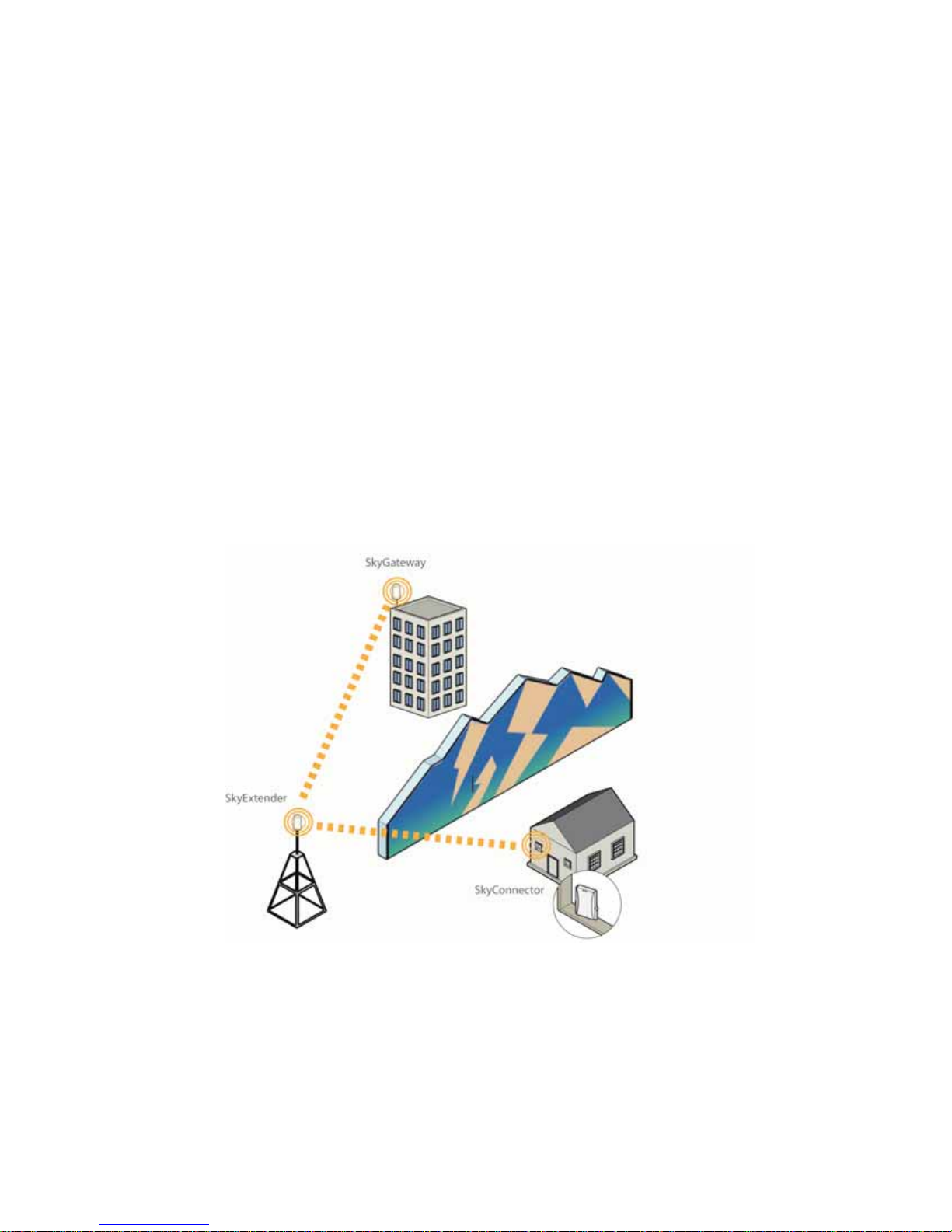
If there are obstructions blocking subscriber access (as in Figure 3-1) or if there are
subscriber sites beyond the distance that a wireless link can maintain, you need to
add one or more SkyPilot Extenders to the network.
Figure 3-1. Using a SkyPilot Extender for network extension behind an
obstruction
Network Planning | 15
Page 24

Preparing SkyPilot Extender Sites
If SkyPilot Extenders are required, perform a survey of possible sites before
beginning installation. For a detailed discussion of site requirements, refer to
SkyGateway/SkyExtender Installation and Setup.
For optimum service, attach SkyPilot Extenders to elevated, fixed locations with
easy and continuous access to power.
Choose an Operating Frequency
All the devices on a SkyPilot network operate on a single frequency. Before
beginning the installation, visit the deployment area and identify an optimum
operating frequency. Use a spectrum analyzer or other frequency-planning tool to
identify the best available frequency for the SkyPilot wireless network—a “clean”
center frequency that permits interference-free operation of devices.
Co-Located SkyPilot Gateway Pro Devices
If you put two of ‘em together, you.....
16 | Chapter 3 Planning Your SkyPilot Network
Page 25

Configuring the SkyPilot Gateway Pro
This chapter provides instructions for configuring the SkyPilot Gateway Pro and
then performing the physical installation.
You should test and configure you SkyPilot Gateway Pro on the bench before
deploying it to the field. To do so, you will need to connect cables and the GPS
antenna.
Chapter Highlights
Cabling
Powering up
Configuring the SkyPilot Gateway Pro
Accessing the command-line interface
4
Provisioning
To provision your SkyPilot Gateway Pro, you must:
Choose a provisioning mode: automatic or manual.
Prepare the network infrastructure. For automatic provisioning, you must
install SkyPilot software on a supported operating system to create your
Network Management System (NMS)
Provisioning | 17
Page 26
Cabling
Ethernet cabling provides power and data connectivity for the SkyPilot Gateway
Pro. Serial cabling provides connectivity for troubleshooting and local
configuration.
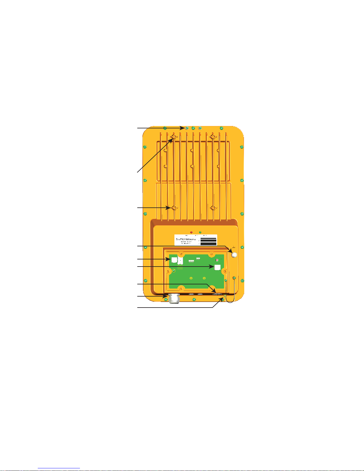
Figure 4-1. Cable Connections and Mounting Holes
GPS
Mount
Holes
Upper
Mount
Holes
Lower
Mount
Holes
Ground Lug
Ethernet Jack
Serial Port
Serial Port
Access Hole
Cable Clamp
GPS SMA
Connector
To install cabling for Ethernet, and optionally serial connections:
1 Remove the access plate from the back of the unit.
2 Connect the Ethernet cable.
a Unscrew the black cable clamp and remove the grey rubber gasket.
b Thread your Ethernet cable through the black plastic cap and then the
grey gasket. In most cases, you can fit the RJ-45 plug through the gasket,
or you can thread the cable through first and them crimp on a connector.
18 | Chapter 4 Configuring the SkyPilot Gateway Pro
Page 27
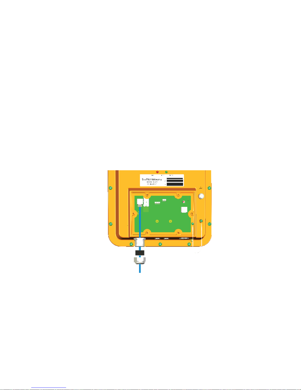
c Thread the Ethernet cable through the connector body and plug it into
the RJ-45 receptacle on the circuit board.
d Makes sure there is a little slack in the cable inside the unit, to act as a
strain relief.
e Insert the grey gasket back into the connector, and then tighten the cap
until the cable is securely held.
3 Connect the serial cable. This is done in the same manner as the Ethernet
cable. You must first remove the plug and installed the supplied cable clamp.
The plug unthreads; use a large flat-blade screwdriver or a coin.
4 Re-attach the cover.
5 Use cable ties or Velcro wraps to secure all the cabling against strain.
Figure 4-2. Exploded View of Cable Clamp Assembly
Rubber Plug
Nut
Cat 5 Cable
Cabling | 19
Page 28
GPS Antenna
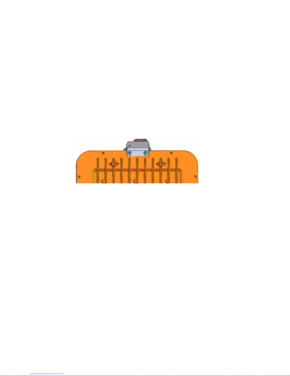
1 Attach the GPS antenna bracket to the top of the unit, on the back, using two
small Phillips screws. This is shown in Figure 4-3.
2 Connect the GPS antenna cable to the SMA connector on the unit bottom.
3 The GPS antenna is magnetic, and will stick to the mounting bracket.
4 Temporarily place the GPS antenna where it can pick up a GPS signal. You can
use a hand-held GPS device, such as an iPhone, to determine if there is
adequate signal strength in your location.
Figure 4-3. GPS bracket
20 | Chapter 4 Configuring the SkyPilot Gateway Pro
Page 29

Powering Up
1 Connect a power cord to the power supply, and plug it in.
2 Connect the Ethernet cable from the SkyPilot Gateway Pro to the port labeled
“Output” on the power supply.
3 Connect an Ethernet cable from the port labeled “Input” to your network.
Monitoring the Power-On Sequence
When the SkyPilot Gateway Pro is powered up, it starts a power-on sequence. You
can monitor itby observing the pair of LED lights on the back of the device. The
power-on sequence may take up to 15 minutes, depending on how quickly the
device can acquire a GPS signal.
NOTEThe SkyPilot Gateway Pro must have access to a GPS signal to complete its
power-on sequence and start making wireless network connections.
Depending on your SkyPilot network configuration, the device may be
unable to connect to the network until the device has been configured.
Table 4-1 provides detailed descriptions of device states indicated by the LEDs..
Table 4-1. SkyPilot Gateway Pro LED Status Lights
Device state LED 1 (left) LED 2 (right)
Startup in progress Slow staggered blinking of both LEDs
Startup failure Off On
Initializing image, acquiring GPS signal Blinks 4 times;
repeats
Initialization failure Fast, synchronized blinking of both LEDs
Successful initialization, but
authorization failure
Successful initialization, but no links
found
Connected Green Blue
Green Off
Green ???
Blinks 4 times;
repeats
Powering Up | 21
Page 30

Configuring the SkyPilot Gateway Pro
To operate on the wireless mesh network, the SkyPilot Gateway Pro requires a
network configuration. A SkyPilot Gateway Pro will not transmit a wireless signal
until it is configured, and it will not be able to connect to other network devices
without a configuration.
SkyPilot offers two modes for provisioning devices with a configuration:
Automatic—Requires the use of SkyPilot EMS software to create
configurations that an unattended central server can distribute to devices on
the wireless mesh network. Although automatic provisioning requires more
initial setup time than manual provisioning, it greatly simplifies the
administration of a growing network.
Detailed procedures for using EMS software are provided in SkyPilot Network
Administration, available from the SkyPilot website at
www.skypilot.com/support/.
Manual—Manual provisioning permits the configuration of only a single
device at a time, creating the minimum settings required for a wireless link and
storing them in the device’s flash (nonvolatile) memory. Manual provisioning is
a logical choice if you’re installing a test network or rolling out a small-scale
installation that isn’t expected to expand.
For more information about provisioning modes, refer to Getting Started with the
SkyPilot Network, available from the SkyPilot website at
www.skypilot.com/support/.
Accessing the Command-Line Interface
SkyPilot devices include a command-line interface which you can use for manual
provisioning and troubleshooting.
You can connect to a device and access its command-line interface through
Telnet over an Ethernet connection or via a terminal session from a console
connected to the device’s RJ-45 serial port. The default IP address is 192.168.0.2
After logging in (user: admin; password: public), you can enter commands at the
command prompt.
22 | Chapter 4 Configuring the SkyPilot Gateway Pro
Page 31

For detailed access instructions for the command-line interface, refer to the
SkyPilot Command-Line Interface Reference.
Manually Provisioning Devices
Manual provisioning stores settings in the device’s flash memory, where they
remain available for recall when the device starts up.
NOTEIf you’re installing a device in a location that poses difficulties, consider
delaying the final mounting until you can confirm that provisioning was
successful.
Table 4-2 summarizes the steps required to manually provision a device.
Table 4-2. Manually Provisioning a Device (Page 1 of 2)
Step Refer to
1 Decide whether to
provision the device using
the command-line
interface or the Web
interface.
(For DualBand/ access
points, you must use the
Web interface.)
2 Prepare the device for
installation by installing
the necessary cabling,
attaching antennas (for
DualBands), and readying
the device for service.
Do not install the device
yet.
3 Power on the device.
”Choosing a Manual Provisioning
Method” in SkyPilot Network
Administration
The appropriate installation manual:
SkyGateway/SkyExtender Installation
and Setup
SkyConnector Indoor Installation
SkyConnector Outdoor Installation
Configuring the SkyPilot Gateway Pro | 23
Page 32

Table 4-2. Manually Provisioning a Device (Page 2 of 2)
Step Refer to
4 Connect a computer to
the device and access the
command-line interface
or the Web interface.
(For DualBands, this step
refers to the SkyPilot
Extender portion of the
device.)
5 Provision the device.
(For DualBands, this step
refers to the SkyPilot
Extender portion of the
device.)
6 For DualBands, reboot the
device, connect a
computer to the device’s
2.4 GHz access point, and
provision the access point.
The appropriate interface reference
manual:
SkyPilot Command-Line Interface
Reference
SkyPilot Web Interface Reference
Either of the following provisioning tool
references, making sure to set at least the
minimum provisioning parameters (refer
to “Required Provisioning Parameters”
and in SkyPilot Network Administration):
SkyPilot Command-Line Interface
Reference
SkyPilot Web Interface Reference
SkyPilot Web Interface Reference
7 Power off the device.
8 Complete the installation. The appropriate installation manual:
SkyGateway/SkyExtender Installation
and Setup
SkyConnector Indoor Installation
SkyConnector Outdoor Installation
9 Power on the device.
24 | Chapter 4 Configuring the SkyPilot Gateway Pro
Page 33

Automatically Provisioning All Network Devices
Table 4-3 summarizes the steps required to automatically provision all devices on
a network. Although it’s possible to provision SkyPilot devices in any order, by
following this sequence you can ensure that devices are able to form links as soon
as they come online.
Table 4-3. Automatically Provisioning All Network Devices (Page 1 of 2)
Step Refer to
1 For new SkyPilot network
deployments, custominstall the operating
system software on the
SkyPilot EMS server.
2 For new SkyPilot network
deployments, install the
server component of
SkyPilot EMS, and then
install the client
component of SkyPilot
EMS on any appropriate
computer.
3 For new SkyPilot Gateway
Pros, set up the DHCP
server and, if the
provisioning server is
behind a firewall, specify
ports for data traffic
between the server and
SkyPilot devices.
The appropriate installation manual:
SkyPilot OS Installation: Red Hat Linux
9.0
SkyPilot OS Installation: Fedora Core 2
and 4
SkyPilot OS Installation: Red Hat
Enterprise Linux ES 3 and 4
SkyPilot EMS Installation
”Adding Devices to the DHCP
Configuration File” in SkyPilot Network
Administration
4 Provision the SkyPilot
Gateway Pro(s).
The following automatic provisioning
topics in SkyPilot Network Administration:
“Provisioning a Device”
“Starting SkyProvision”
“SkyProvision Display Pane”
”Searching for Configured Devices”
Configuring the SkyPilot Gateway Pro | 25
Page 34

Table 4-3. Automatically Provisioning All Network Devices (Page 2 of 2)
Step Refer to
5
For new SkyPilot Gateway
Pros, complete the
installation and power it
on.
6 (Optional) Log in to the
SkyPilot Gateway Pro and
configure the
management VLAN.
7 Provision the SkyPilot
Extender(s).
8 For DualBands, provision
the access point(s).
SkyGateway/SkyExtender Installation and
Setup
”The SkyPilot EMS Interface” in SkyPilot
Network Administration
The following automatic provisioning
topics in SkyPilot Network Administration:
“Provisioning a Device”
“Starting SkyProvision”
“SkyProvision Display Pane”
”Searching for Configured Devices”
For information about access point
settings, refer to SkyPilot Network
Administration. For configuration
procedures, refer to the SkyPilot Web
Interface Reference
9 For new SkyPilot
Extenders, install the
device and power it on.
10 Provision the SkyPilot
Connector(s).
11 For new SkyPilot
Connectors, install the
device and power it on.
SkyGateway/SkyExtender Installation and
Setup
Same as for step 7.
The appropriate installation manual:
SkyConnector Indoor Installation
SkyConnector Outdoor Installation
Configuring Adjacent SkyPilot Gateway Pros
is quite tricky....
26 | Chapter 4 Configuring the SkyPilot Gateway Pro
Page 35

Installing the SkyPilot Gateway Pro
This chapter provides instructions for configuring the SkyPilot Gateway Pro and
then performing the physical installation.
Install Devices
You can ensure optimum operation—and reduce administrative overhead—by
installing your network devices in this order:
SkyPilot Network Management System
SkyPilot Gateway Pro
SkyPilot Extenders (optional)
SkyPilot Connectors.
You install the SkyPilot Gateway Pro first because, as the base station of the
SkyPilot wireless network, it must be present in order for other devices to establish
5
network links. When provisioned and powered on, the SkyPilot Gateway Pro
immediately starts transmitting hello beacons that SkyPilot Extenders and Sky
Connectors use to form links.
After installing the SkyPilot Gateway Pro, you add SkyPilot Extenders (if required)
and then SkyPilot Connectors. Upon powering on, each device responds to the
base station’s hello beacon and starts forming links with the SkyPilot Gateway Pro.
Each device attempts to establish as many links as possible before choosing an
optimum path.
After establishing network links, SkyPilot Extenders on your network also begin
transmitting hello beacons, extending the range of beacons available to other
devices. (SkyPilot Connectors do not transmit hello beacons.)
Install Devices | 27
Page 36
Mounting
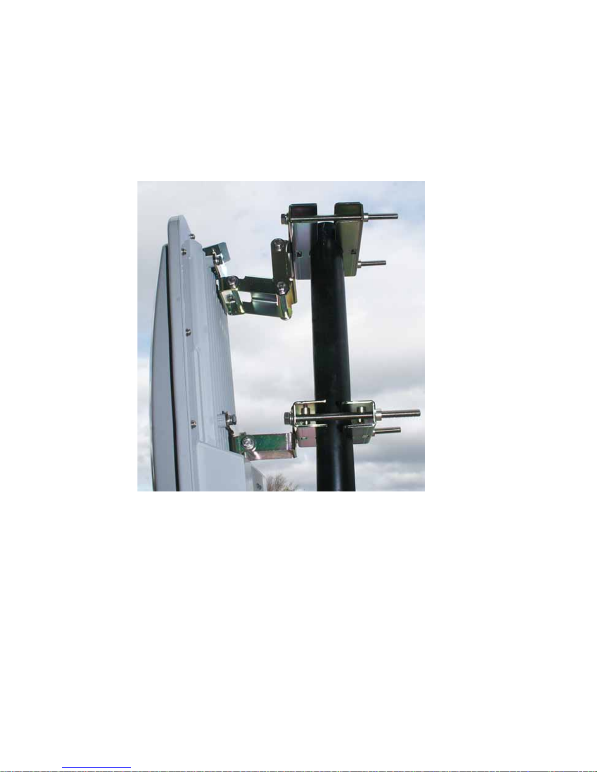
The SkyPilot Gateway Pro uses two hinged mounting brackets to allow it to be
tilted up or down slightly, as needed.
Figure 5-1. Mounted SkyPilot Gateway Pro
.
To mount the SkyPilot Gateway Pro:
IMPORTANTIt is the installer’s responsibility to verify that the support pole
and its installation method are of sufficient strength to withstand
onsite weather conditions. (The supplied mounting bracket and
screws are certified to withstand a 150 mph wind force.)
1 Attach one of the pole-clamp assemblies to the pole at the height you want
for the top of the unit. Make sure the threaded holes are facing up. Use the
long bolts in the kit.
28 | 5 Installing the SkyPilot Gateway Pro
Page 37
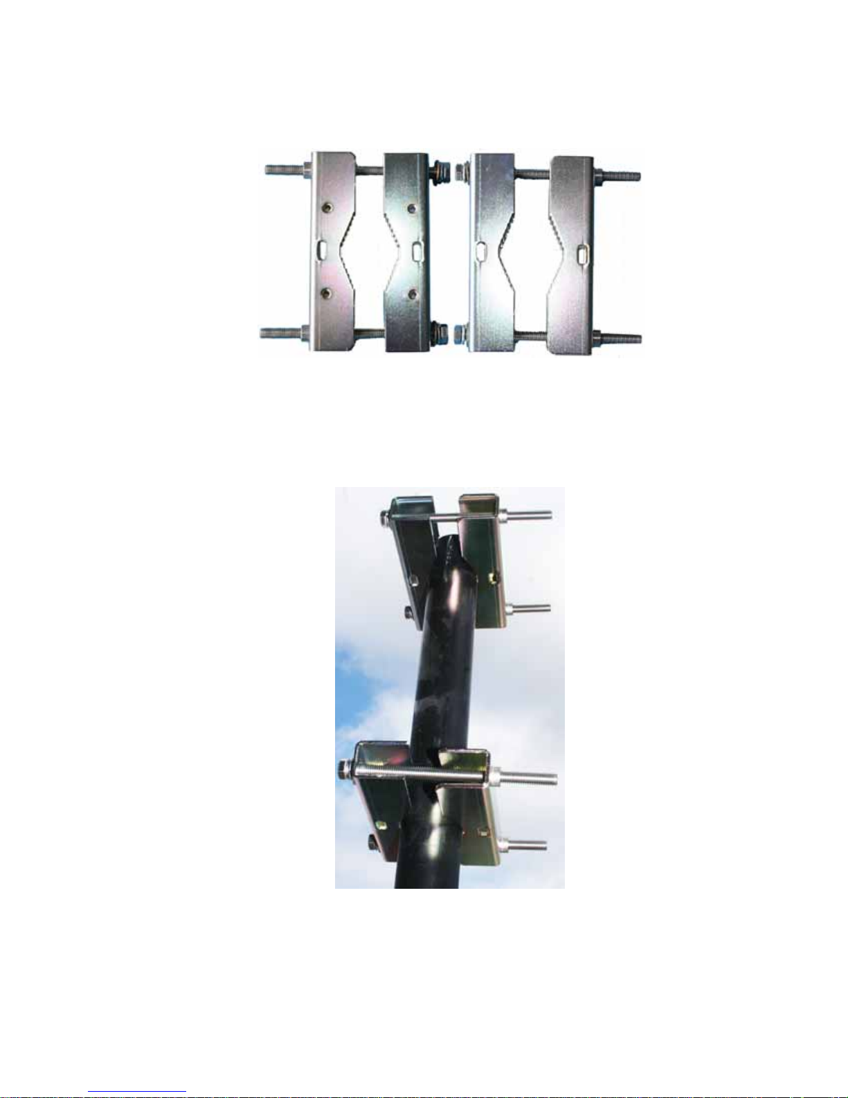
Figure 5-2. Pole Clamps: Top View at Left; Bottom View at Right
2 Attach the second pole-clamp assembly to the pole, about nine inches lower
than the first. Again, make sure the threaded holes are facing up.
Figure 5-3. Pole Clamps Attached to Pole
3 Attach the hinged brackets to the SkyPilot Gateway Pro using the supplied
1/4-28 UNC bolts. These have hex heads. Do not use the Phillips-head screws.
Use thread-locking compound.
Mounting | 29
Page 38
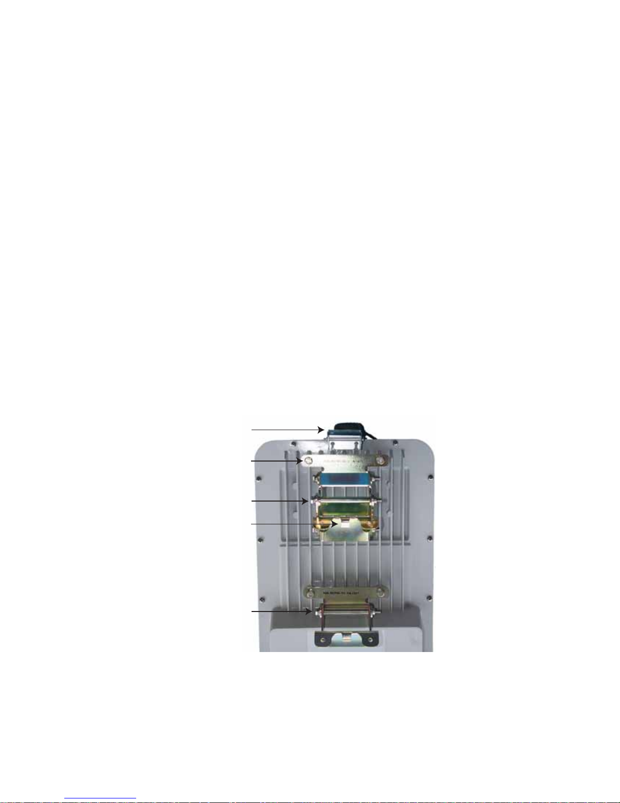
The brackets should be attached so that the body of the bracket is below the
mounting holes. This, in turn, will orient the hook-tab, which is at the other
end of the bracket, down.
IMPORTANTThe double-hinged mounting bracket and the single-hinged
bracket , together, allow you to tilt the unit. If you need to tilt it
down, use the double-hinged bracket on top. If you need to tilt it
up, use the double-hinged bracket on the bottom.
IMPORTANTThe holes in the unit are fine-thread. DO NOT use 1/4-20 UNC
(coarse thread) hardware in these holes.
IMPORTANTThe SkyPilot Gateway Pro case is aluminum. Do no over-torque
the mounting bolts.
NOTEYour SkyPilot Gateway Pro can be wall-mounted. You will need lag bolts or
other fasteners suitable for attaching to the wall. Use them to attach onehalf of the pole clamp to the wall, then hang the SkyPilot Gateway Pro as
described below.
Figure 5-4. SkyPilot Gateway Pro with Mounting Brackets Attached
GPS antenna
on bracket
1/4-28 hex-head bolts
Double-hinge bracket
Tab
Single-hinge bracket
30 | 5 Installing the SkyPilot Gateway Pro
Page 39
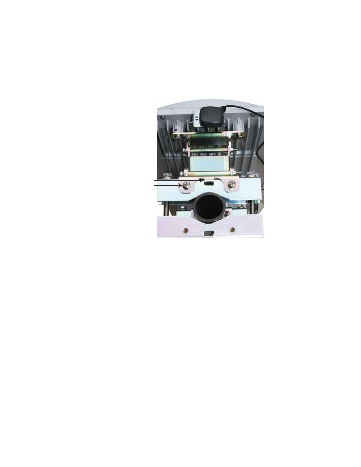
4 The SkyPilot Gateway Pro can now be hung from the pole clamps. The tabs fit
into recesses in the pole clamps. Use the 1/4-20 Phillips screws to secure the
brackets to the clamps.
Figure 5-5. SkyPilot Pro-Top View - Showing Tabs & Screws
Hinge bolts
Tab
1/4-20
Phillips-head
screws
5 Adjust the angle of the unit, and then tighten the hinge bolts.
Mounting | 31
Page 40

32 | 5 Installing the SkyPilot Gateway Pro
Page 41

Verifying Connectivity
After provisioning and installing your SkyPilot devices, you should perform the
procedures in the following sections to confirm that the devices are properly
connected to the network.
Confirming SkyPilot Gateway Pro Connectivity
There are two ways to confirm SkyPilot Gateway Pro connectivity:
Check the LED status lights on the SkyPilot Gateway Pro to verify that the
device is fully online.
See Table 6-1for a summary of what the LED status lights mean. For a detailed
description of the status lights, refer to SkyGateway/SkyExtender Installation
and Setup.
Table 6-1. SkyPilot Gateway Pro LED status lights
6
Device state Link LED Activity LED
Startup in progress Slow staggered blinking of both LEDs
Startup failure Off On
Initializing image (and
acquiring GPS signal)
Initialization failure Fast, synchronized blinking of both LEDs
Successful initialization, but
authorization failure
Connected On On
Blinks 4 times;
repeats cycle
On Off
Blinks 4 times;
repeats cycle
Confirming SkyPilot Gateway Pro Connectivity | 33
Page 42

From the command line, use the ping command to verify that you can reach
the device’s default gateway
For example:
> ping 192.168.5.1
PING 192.168.5.1: 56 data bytes
64 bytes from 192.168.5.1: icmp_seq=0. time=11. ms
64 bytes from 192.168.5.1: icmp_seq=1. time=12. ms
64 bytes from 192.168.5.1: icmp_seq=2. time=12. ms
----192.168.5.1 PING Statistics---3 packets transmitted, 3 packets received, 0% packet loss
round-trip (ms) min/avg/max = 0/16/32
34 | 6 Verifying Connectivity
Page 43

Confirming SkyPilot Extender and SkyPilot
Connector Connectivity
There are four ways to confirm SkyPilot Extender and SkyPilot Connector
connectivity. You can use any method at any time.
Check the LED status lights on the device to verify that the device is fully
online.
For a summary of what the LED status lights mean, see Table 6-2 (for SkyPilot
Extenders) or Table 6-3 (for SkyPilot Connectors). For a detailed description of
the status lights, refer to the installation guide for the device.
Table 6-2. SkyPilot Extender/DualBand LED status lights
Device state Link LED Activity LED
Startup in progress Slow staggered blinking of both LEDs
Startup failure Off On
Initializing image (and
acquiring GPS signal)
Initialization failure Fast, synchronized blinking of both LEDs
Successful initialization, but
can’t locate hello
Successful initialization;
heard hello on antennas
with power levels in the
proper RSSI range
Successful initialization; link
is not optimized, or is in
pre-authorization
Successful initialization; link
is in standby state on
antenna and modulation
rate
Connected On On
Blinks 4 times;
repeats cycle
On Off
Off Blink (modulation
Slow blink Blink (modulation
Fast blink Blink (modulation
Blinks 4 times;
repeats cycle
rate-based)
rate-based)
rate-based)
Confirming SkyPilot Extender and SkyPilot Connector Connectivity | 35
Page 44

Table 6-3. SkyPilot Connector LED status lights
LED LED state Device state
Lan Link Steady illumination SkyPilot Connector is connected to
another device via its Ethernet port
LAN Act Blinking Device is transmitting or receiving
data via its Ethernet port
WAN Link Blinking (fast blink
when device is in
standby mode)
Device is attempting to establish an
authorized connection on the
wireless network
Steady illumination Device is connected to the wireless
network
WAN Act None Device cannot detect a wireless
network
Blinking Device is within the coverage area of
a wireless network. Blink indicates
signal strength:
Fast (8x per second): excellent
Medium (4x per second): good
Slow (<1x per second): poor
From the command line, use the show link command to confirm that an
active link exists.
The device is online if the output displays an act path (active path) link
state.
For example:
Node Id LType NType State RSSI LTxMod RTxMod LAnt RAnt
----------------- ----- ----- --------- ---- ------ ------ ---- --00:0a:db:00:00:43 data ext act path 39 48 36 2 4
Use the traceroute command to confirm that you can send and receive
data across the wireless network.
The traceroute command performs a SkyPilot protocol trace that shows
the path to the SkyPilot Gateway Pro. Entering the traceroute command
36 | 6 Verifying Connectivity
Page 45

without arguments returns a path that the device identifies as its exit from the
network.
For example:
> traceroute
traceroute to 00:0a:db:00:00:a6
>> 1 (48) --> 00:00:43 --> (36)
2 (36) --> 00:00:a6 --> (36)
Use the ping command to verify that you can reach the device’s default
gateway.
For example:
> ping 192.168.5.1
PING 192.168.5.1: 56 data bytes
64 bytes from 192.168.5.1: icmp_seq=0. time=11. ms
64 bytes from 192.168.5.1: icmp_seq=1. time=12. ms
64 bytes from 192.168.5.1: icmp_seq=2. time=12. ms ----
192.168.5.1 PING
Statistics---- 3 packets transmitted, 3 packets received, 0%
packet loss round-trip (ms) min/avg/max = 0/16/32
Confirming SkyPilot Extender DualBand
Access Point Connectivity
There are four ways to confirm SkyPilot Extender DualBand access point
connectivity:
Use the ping command to verify that the access point is up and running—for
example,
For SkyPilot firmware versions 1.2p3 and later, use the show version ap
command to verify the firmware version and, indirectly, that proper heartbeats
are being sent from the PePLink Linux access point.
From the command line, enable debugging (using the debug on
command) and use the set log apwatchdog 3 command to display
successful or failed heartbeat updates, reboot notices, factory resets, and so
on.
Using an 802.11b/g wireless card, connect to the default SSID, a string
representation of the SkyPilot Extender’s MAC address with the WPA
passphrase
ping 192.168.0.3.
publicpublic.
Confirming SkyPilot Extender DualBand Access Point Connectivity | 37
Page 46

Once connected, use the ping command to verify that you can reach both
the SkyPilot Extender and the access point. For example:
> ping 192.168.0.3
PING 192.168.5.1: 56 data bytes
64 bytes from 192.168.0.3: icmp_seq=0. time=11. ms
64 bytes from 192.168.0.3: icmp_seq=1. time=12. ms
64 bytes from 192.168.0.3: icmp_seq=2. time=12. ms ----
192.168.5.1 PING
Statistics---- 3 packets transmitted, 3 packets received, 0%
packet loss round-trip (ms) min/avg/max = 0/16/32
> ping 192.168.0.2
PING 192.168.5.1: 56 data bytes
64 bytes from 192.168.0.2: icmp_seq=0. time=11. ms
64 bytes from 192.168.0.2: icmp_seq=1. time=12. ms
64 bytes from 192.168.0.2: icmp_seq=2. time=12. ms ----
192.168.5.1 PING
Statistics---- 3 packets transmitted, 3 packets received, 0%
packet loss round-trip (ms) min/avg/max = 0/16/32
38 | 6 Verifying Connectivity
Page 47

Troubleshooting
After making an Ethernet or serial connection to the SkyPilot Gateway Pro, you can
manage and troubleshoot the device using a wide range of commands available
through the command-line interface.
For detailed troubleshooting procedures, refer to the “Troubleshooting” section in
SkyPilot Network Administration. There you’ll find troubleshooting procedures for:
Power-on problems
Ethernet connectivity problems
IP connectivity problems
SkyPilot Gateway Pro Transmission problems
Link failure problems
Troubleshooting | 39
Page 48

40 | 6 Verifying Connectivity
Page 49

Grounding Guidelines
This appendix provides some guidelines for properly grounding the SkyPilot
Gateway Pro.
Proper grounding protects both your SkyPilot device and equipment connected
to it. For the surge protection circuitry built into the SkyPilot equipment to be
effective, proper grounding of the unit is necessary. This is especially true if you’re
installing devices on tall structures, or in areas subject to lightning.
NOTEThe techniques described in this appendix are intended as general
guidelines only and do not constitute a comprehensive guide covering all
installation scenarios. For maximum protection, contact a qualified
installation specialist who is familiar with your operating environments. If
lightning is a threat in your area, consider a consultation with a lightning
and transient protection specialist.
General Grounding Strategy
A
To ensure optimum reliability, properly ground the metal base of the SkyPilot device. The
most efficient way to ground the device is to use an 8 GA or larger wire to connect it to a
ground point on the mounting structure or tower.
The three most common ground points are:
A cold-water pipe. Make sure it is well-connected to earth.
The primary grounding point of the AC electrical system of the building.
A 10-foot or longer copper-clad ground rod driven into the earth. For a tower
with multiple legs, you need one ground rod per leg and a ground wire loop
connecting each of the rods; see Figure 12.
Grounding Guidelines | 41
Page 50
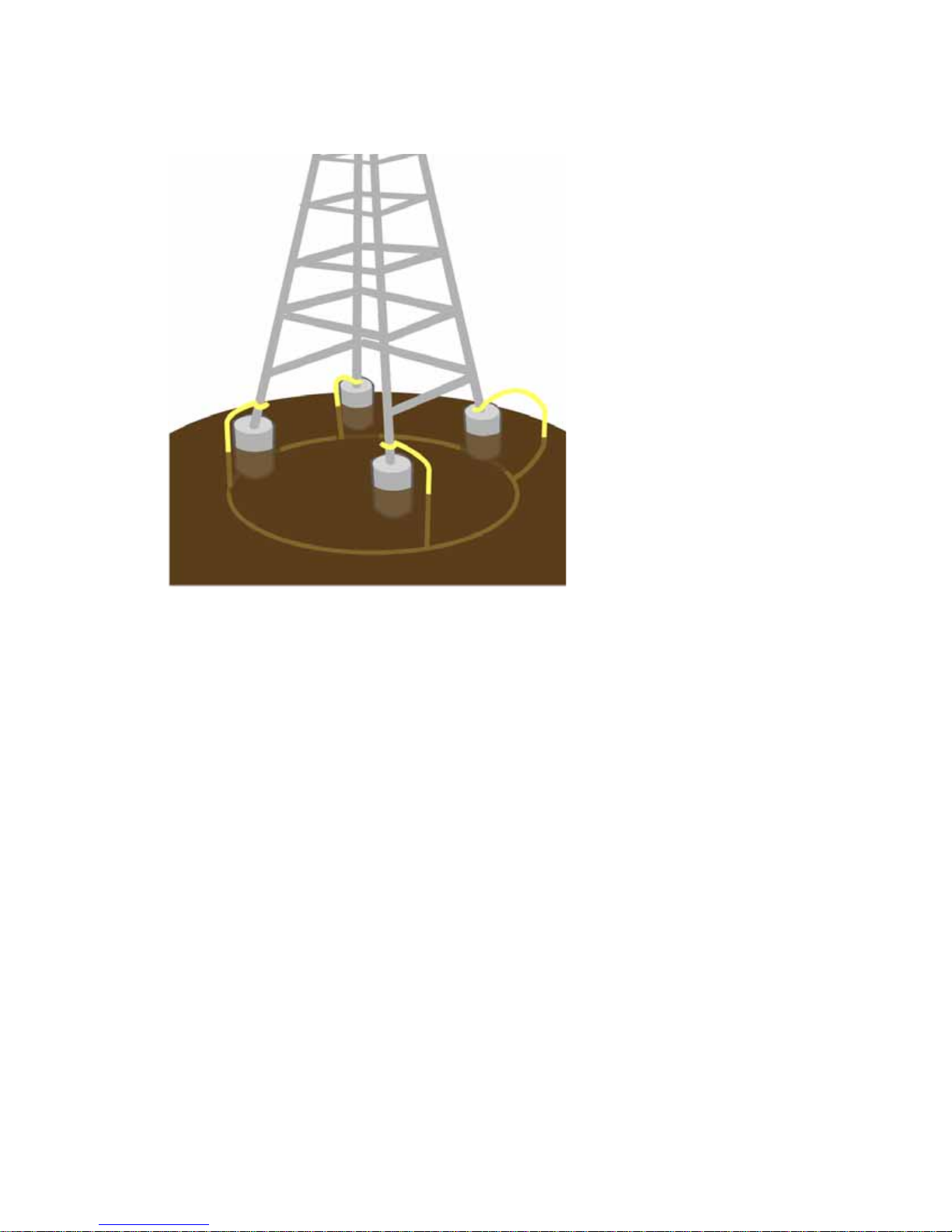
Figure 12. Ground wire loop
A
Making Connections “Gas-Tight”
Regardless of the grounding point you use, make sure the connections are “gas-
tight”—capable of retaining low resistance and integrity over time and with
exposure to the elements.
Use of an antioxide compound and proper sealing is essential. For protection
against corrosion, wrap all connections with Scotch® 130C tape.
Checking Cold-Water Pipe Integrity
If you’re using a cold-water pipe for grounding, verify the integrity of the ground.
In some cases, sections of metal cold-water pipes may have been repaired or
extended with PVC material. PVC material or a dielectric union will render a cold-
water pipe ground unacceptable for grounding.
42 | Appendix A Grounding Guidelines
Page 51

Measuring Resistance
Verify that there is no more than 5 ohms of resistance between any two ground
points in the entire system. Also make sure that all ground points on a structure
are tied together. For example, if you use a ground rod and a cold-water pipe as
grounding points at different locations on the same structure, you must tie them
together.
Adding Surge Protection
If you’re installing a SkyPilot device in an area that’s subject to lightning storms,
SkyPilot recommends installing a surge protection device (SPD) at both ends of
the Ethernet cable—one at the SkyPilot device and one at the point of entry to a
building or enclosure.
SkyPilot offers SPDs with bracket and cabling designed for use with SkyPilot
equipment. For more information, visit SkyPilot customer support at
www.skypilot.com/support/ to view accessory guides for SkyPilot-branded surge
A
protection solution. (You may also purchase SPDs from third-party vendors.)
Grounding Checklist
When grounding a SkyPilot device, use the following checklist to confirm that
your installation is adequately protected from power surges and lightning.
Connect a ground wire from the SkyPilot device to a ground system on the
building or tower.
Use shielded CAT5 cabling and connect the drain wire of the shield to ground
at the SkyPilot device. (Leave the other end of the drain wire unconnected.)
Use the proper size down lead to connect a SkyPilot device on a roof or tower
to the ground system of indoor equipment.
Verify that all points of the ground system are tied together with less than 5
ohms resistance between any two points.
Adding Surge Protection | 43
Page 52

Run the CAT5 cable inside the tower structure, tying the cable to the tower leg
at every 4 feet of length. For increased protection, run the CAT5 cable through
metallic conduit installed on the tower.
Bleed off any static charge by installing a streamer-delaying, static-dissipation
array above the SkyPilot device.
Install all lightning and surge protection devices in accordance with UL 96A
installation requirements for lightning protection systems and the NFPA 780
standard for lightning protection.
A
44 | Appendix A Grounding Guidelines
Page 53

Specifications
This appendix provides technical specifications for the SkyPilot Gateway Pro
(Table C-1),
Table C-1. SkyPilot Gateway Pro Specifications (Page 1 of 3)
Wireless
Specifications
Frequency bands 5.150–5.450 GHz
5.450–5.725 GHz
5.725–5.850 GHz
EIRP 44.5 dBm/28.2W peak, 36 dBm/4W average, 33 dBm/2W
average, 30 dBm/1W average, or 36 dBm/4W peak
(EIRP selected for country-specific regulations)
Media access Time Division Duplex (TDD)
Modulation technique OFDM with adaptive modulation
Modulation rates 6–54 Mbps
C
Throughput UDP: Up to 20 Mbps
TCP: Up to 10.5 Mbps
Latency 10–12 ms round trip per hop
Antennas Electronically-steered antenna, 180-degree coverage
Channel width 20 MHz
Channel resolution 5 MHz frequency control
Receive sensitivity -90 dBm at 6 Mbps modulation
Connectivity SkyPilot Gateway Pro connects with:
SkyPilot Extenders,
SkyPilot Extender DualBands
SkyPilot Connectors.
Authentication MD5-based certificates
Encryption 128-bit AES on all wireless links
Specifications | 49
Page 54

Table C-1. SkyPilot Gateway Pro Specifications (Page 2 of 3)
Product Specifications
Connectors RJ-45: Ethernet connection (10/100Base-T) and power
(Power over Ethernet)
RJ-45: RS-232 serial for local management
Mounting Tower, utility pole, building, or other infrastructure, outside
pole diameter up to 2.5". Wall mount possible.
Range Up to 10 miles (16 km)
LEDs Wireless activity, wireless link
Dimensions 17" (43 cm) H x 11.6" (29.5 cm) wide x 5.5” (14 cm) thick
Weight 11 pounds (5 kg), basic unit
17 pounds (7.7 kg) with standard mounting hardware
Operating temperature -40° to 131° F (-40° to 55° C)
Wind loading Up to 150 mph (240 km/h)
Enclosure/humidity NEMA-4X
External PoE PSE Power 110–230 VAC, 50–60 Hz input, 16 watts maximum
Certifications FCC Part 15, FCC 47 CFR Part 15, Class B USA; compliance
with UL safety standards, CE, C-Tick, IC RSS210 Issue 5
EMI and susceptibility FCC Part 15.107 and 15.109
Warranty One-year limited warranty on hardware and software
Security
Authentication MD5-based certificates
Encryption AES
Filtering Based on protocol type, IP port ID, and configurable IP
address list
Network management
Command-line interface Console via RS-232 serial port or SSH
NMS Integration SNMP v2c
50 | Appendix C Specifications
Page 55

Table C-1. SkyPilot Gateway Pro Specifications (Page 3 of 3)
GUI configuration SkyProvision™ software and Web interface
GUI EMS SkyPilot EMS™ software
IP address DHCP or static. 192.168.02. default
Firmware Multiple versions of firmware stored in nonvolatile memory;
updated via FTP
Configuration file XML over HTTP
QoS (Quality of Service)
Prioritization 802.1p-based; based on protocol type, IP address, port ID,
and configurable IP address list
Traffic shaping Per-device rate limits upstream and downstream
Monitoring and MIB support
Supported MIBs MIB-II (RFC 1213); EtherLike (RFC 2665); Bridge (RFC 1493);
SkyPilot private MIB
Local management RS-232 Serial Console Port
Remote management Command-line interface via Telnet, SNMP 2c, Web interface
Topology
Configurations Mesh, point-to-multipoint, point-to-point
Specifications | 51
Page 56

52 | Appendix C Specifications
Page 57

Pinouts
This appendix provides pinouts for connectors and adapters to connect to the
Ethernet interface port labeled “CPE” on the SkyPilot Gateway Pro power supply
and the device’s serial interface.
RJ-45 Pins
Table D-1 lists the RJ-45 pin assignments.
Table D-1. RJ-45 Pin Assignments
Pin Assignment
1 Ethernet
2 Ethernet
3 Ethernet
D
4 Power
5 Power
6 Ethernet
7 Power
8 Power
Pinouts | 53
Page 58
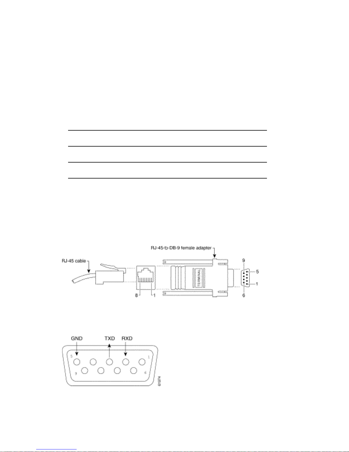
DB-9 Adapter
Table D-2 lists connecting pins between the SkyPilot Gateway Pro “CPE” port
(RJ-45 connector) and a standard computer DB-9 serial port.
Table D-2. RJ-45 Pin Assignments
SkyPilot Gateway/Extender
“CPE” port
Signal Pin Pin Signal
TxD 3 2 RxD
GND 4 5 GND
RxD 6 3 TxD
Computer serial port
The following figures show the connection between the SkyPilot Gateway Pro
“CPE” port and a standard computer DB-9 serial port, the DB-9 pinouts, and the
cable-pin correspondence.
Figure D-1. RJ-45 to DB-9 physical connectors
Figure D-2. DB-9 pins
54 | Appendix D Pinouts
Page 59
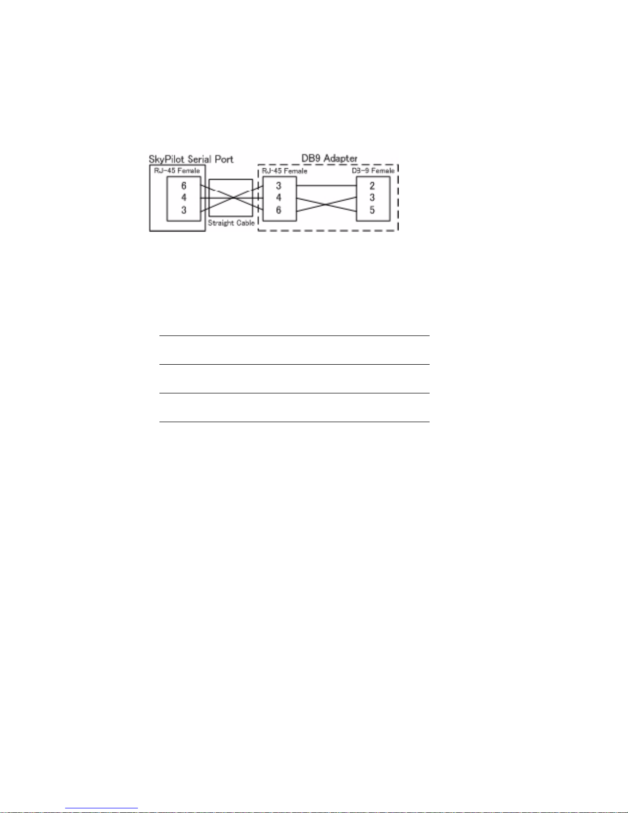
If you’re using a straight through cable, the connection can be visualized as shown
in Figure D-3.
Figure D-3. Straight through cabling
Although there is no official standard, the connector wire colors typically are as
described in Table D-3.
Table D-3. Typical RJ-45 DB-9 Wire Colors
Color RJ-45 pin DB-9 pin
Black 3 2
Yellow 6 3
Red 4 5
DB-9 Adapter | 55
Page 60

Regulatory information
Federal Communications Commission (FCC) compliance notices
This section includes the following FCC statements for the SP-5200-A and related SkyPilot by Trilliant
products:
• FCC ID: RV7-GWPRO
• Class A Interference Statement
• RF Radiation Exposure and Hazard Warning
• Non-Modification Statement
• Deployment Statement
Class A Interference Statement
This equipment has been tested and found to comply with the limits for a Class A digital device, pursuant to
Part 15 of the FCC Rules. These limits are designed to provide reasonable protection against harmful
interference in a commercial installation. This equipment generates, uses, and can radiate radio frequency
energy and, if not installed and used in accordance with the instructions, may cause harmful interference to
radio communications. However, there is no guarantee that interference will not occur in a particular
installation. If this equipment does cause harmful interference to radio or television reception, which can be
determined by turning the equipment off and on, the user is encouraged to try to correct the interference by
one or more of the following measures:
• Reorient or relocate the receiving antenna.
• Increase the separation between the equipment and receiver.
• Connect the equipment into an outlet on a circuit different from that to which the receiver is connected.
• Consult the dealer or an experienced radio/TV technician for help.
FCC Caution:
This device complies with Part 15 of the FCC Rules. Operation is subject to the following two conditions:
(1) This device may not cause harmful interference, and (2) this device must accept any interference
received, including interference that may cause undesired operation.
RF Radiation Exposure & Hazard Statement
To ensure compliance with FCC RF exposure requirements, this device must be installed in a location such
that the antenna of the device will be greater than 20 cm (8 in.) away from all persons. Using higher gain
antennas and types of antennas not covered under the FCC certification of this product is not allowed.
Installers of the radio and end users of the product must adhere to the installation instructions provided in
this manual. This transmitter must not be co-located or operated in conjunction with any other antenna or
transmitter.
Non-Modification Statement
Use only the supplied internal antenna. Unauthorized antennas, modifications, or attachments could
damage the SP-5200-A and related SkyPilot by Trilliant products and violate FCC regulations. Any changes
or modifications not expressly approved by the party responsible for compliance could void the user's
authority to operate this equipment.
Deployment Statement
This product is certified for indoor deployment only in the 5150 – 5250 MHz band. Do not install or use this
product outdoors in that frequency band in the United States.
Dynamic Frequency Selection (DFS) in the 5.0 GHz UNII bands
The SP-5200-A has been prohibited from operating in the 5600 to 5650 MHz frequency band for the US and
Canada in order to comply with the DFS requirements as outlined in the FCC Part 15, Subpart E rules.
27 | Regulatory Information
Page 61

Canadian IC Statements
IC: 6028A-GWPRO
This device complies with ICES-003 and RSS-210 of Industry Canada.
Operation is subject to the following two conditions:
1. This device may not cause interference, and
2. This device must accept any interference, including interference that may cause undesired operation of
the device.
Ce dispositif est conforme aux normes NMB003 et CNR-210 d’Industrie Canada.
1. L’utilisation de ce dispositif est autorisée seulement aux conditions suivantes :
2. il ne doit pas produire de brouillage et l’utilisateur du dispositif doit être prêt à accepter tout brouillage
radioélectrique reçu, même si ce brouillage est susceptible de compromettre le fonctionnement du dispositif.
RF Radiation Exposure & Hazard Statement
To ensure compliance with RSS-102 RF exposure requirements, this device must be installed in a location
such that the antenna of the device will be greater than 20 cm (8 in.) away from all persons. Using higher
gain antennas and types of antennas not covered under the IC certification of this product is not allowed.
Installers of the radio and end users of the product must adhere to the installation instructions provided in
this manual. This transmitter must not be co-located or operated in conjunction with any other antenna or
transmitter.
Exposition aux radiations RF & Mention de danger
Pour assurer la conformité avec les exigences RSS-102 d'exposition aux RF (Radio Fréquences), cet
appareil doit être installé dans un endroit ou l'antenne de l'appareil sera située à une distance de plus de 20
cm (8 po) de toutes personnes. L’utilisation d'antennes à gain plus élevé et les types d'antennes qui ne sont
pas couverts en vertu de la certification IC de ce produit n'est pas autorisée. Les installateurs de la radio et
les utilisateurs du produit final doivent se conformer aux instructions d'installation fournies dans ce manuel.
Cet émetteur ne doit pas être co-implanté ou exploité en conjonction avec toute autre antenne ou
transmetteur.
Deployment Statement
This product is certified for indoor deployment only in the 5150 – 5250 MHz band. Do not install or use this
product outdoors in that frequency band in Canada.
Déclaration de déploiement
Ce produit est certifié pour le déploiement à l'intérieur tout en rencontrant les limites de cette bande de
fréquences: 5150 - 5250 MHz. Ne pas installer ou utiliser ce produit à l'extérieur au Canada, si cette bande
de fréquences ne peut ne peut être rencontrée.
29 | Regulatory Information
Page 62
SAFETY INFORMATION
Hazard Warning!
High Voltage. This situation or condition can cause injury due to electric shock.
Warnung!
Lesen und befolgen Sie die Warnhinweise und Anweisungen, die auf dem Produkt
angebracht oder in der Dokumentation enthalten sind.
Warning!
Read and follow all warning notices and instructions marked on the product or
included in the documentation.
Warnung!
Lesen und befolgen Sie die Warnhinweise und Anweisungen, die auf dem Produkt
angebracht oder in der Dokumentation enthalten sind.
Warning!
Only use attachments and accessories specified and/or sold by the manufacturer.
Warnung!
Verwenden Sie nur Zusatzgeräte und Zubehör angegeben und / oder verkauft wurde
durch den Hersteller.
Warning!
Refer all servicing to qualified service personnel. Servicing is required when the
device has been damaged in any way, such as power-supply cord or plug is
damaged, liquid has been spilled or objects have fallen into the device, the device
has been exposed to rain or moisture, does not operate normally, or has been
dropped.
Warnung!
Das Gerät sollte nur von qualifizierten Fachkräften gewartet werden. Eine Wartung
ist fällig, wenn das Gerät in irgendeiner Weise beschädigt wurde, wie bei
beschädigtem Netzkabel oder Netzstecker, falls Flüssigkeiten oder Objekte in das
Gerät gelangen, das Gerät Regen oder Feuchtigkeit ausgesetzt wurde, nicht
ordnungsgemäß funktioniert oder fallen gelassen wurde.
Warning!
Do not open the chassis. There are no user-serviceable parts inside. Opening the
chassis will void the warranty unless performed by an Trilliant service center or
licensed facility.
Warnung!
Öffnen Sie das Gehäuse nicht. Keine der Geräteteile können vom Benutzer gewartet
werden. Durch das Öffnen des Gehäuses wird die Garantie hinfällig, es sei denn,
solche Wartungsarbeiten werden in einem Trilliant-Service-Center oder einem
lizenzierten Betrieb vorgenommen.
29 | Regulatory Information
 Loading...