

Page 1

GENERAL lNFC9kMATlON
Page 2

-.
Page 3
Table of Contents
General Description
introduction .
System Components .
Key Service Unit . .
TalkToTM 6 16 Set . .
Door Answering . .
Power Fail Unit . .
Features
Standard Features
Optional Features . . . .
. .
Technical Specifications
System Capabilities . . . . . .
Environmental Requirements .
Power Requirements . . . . .
Signaling
Number Plan’
Connectors . . .
. . . . . .
. . . . .
Ordering Information
Key Service Units . . . .
TalkToTM 6 16 Sets . . .
Door Answering Option . . .
Power Fail Transfer Option
Miscellaneous Parts . . . .
. .
. .
Page
. .
.
.
. .
. .
. .
.
.
.
.
.
. . . . .
. . ._.
.
. .
......
......
......
......
......
......
. .
......
......
......
......
5
6
.
7
7
7
7
7
7
12
12
12
12
12
.
.
. . .
, .
.
. . .
.
. .
.
.
. . .
. .
.
1
Page 4
GENERAL DESCRIPTION
Introduction
The Ta/kToTM 616 is a compact, reliable Electronic Key
Telephone System (EKTS) that can be used in a standalone mode, behind a PABX, or with Centrex. The system
has a maximum capacity of six Central
Office/PBX/Centrex lines, sixteen telephone set extensions
and three intercom paths. Each telephone extension re
quires the use of a TalkTo proprietary telephone set. Two
versions of the set are available, one with handsfree operation, and one without.
The system employs solid state space division switching
with stored program control. The TalkTo 676 Set is available with or without handsfree operation and is equipped
with its own microprocessor. The overall operation of the
system is controlled by a microprocessor based in the Key
Service Unit (KSU). This technology ensures reliable system
communication, as well as user friendly service and feature
operation.
The system has a wide variety of standard features.
Other features are available as options. All are described
under Features. Any system programming for feature opera-
tion is entered at a control set using access codes and the
tone dial pad.
Installation is low cost, fast and effective, using a standard twenty-five pair connector, modular cords, jacks and
twopair cable, in a home run (star) configuration,
System Components
/I
3
i
r
The main components of the TalkTo 616 System are a
Key Service Unit, and a TalkTo 676 Set. Door Answer and
Power Fail Transfer Units are available as options.
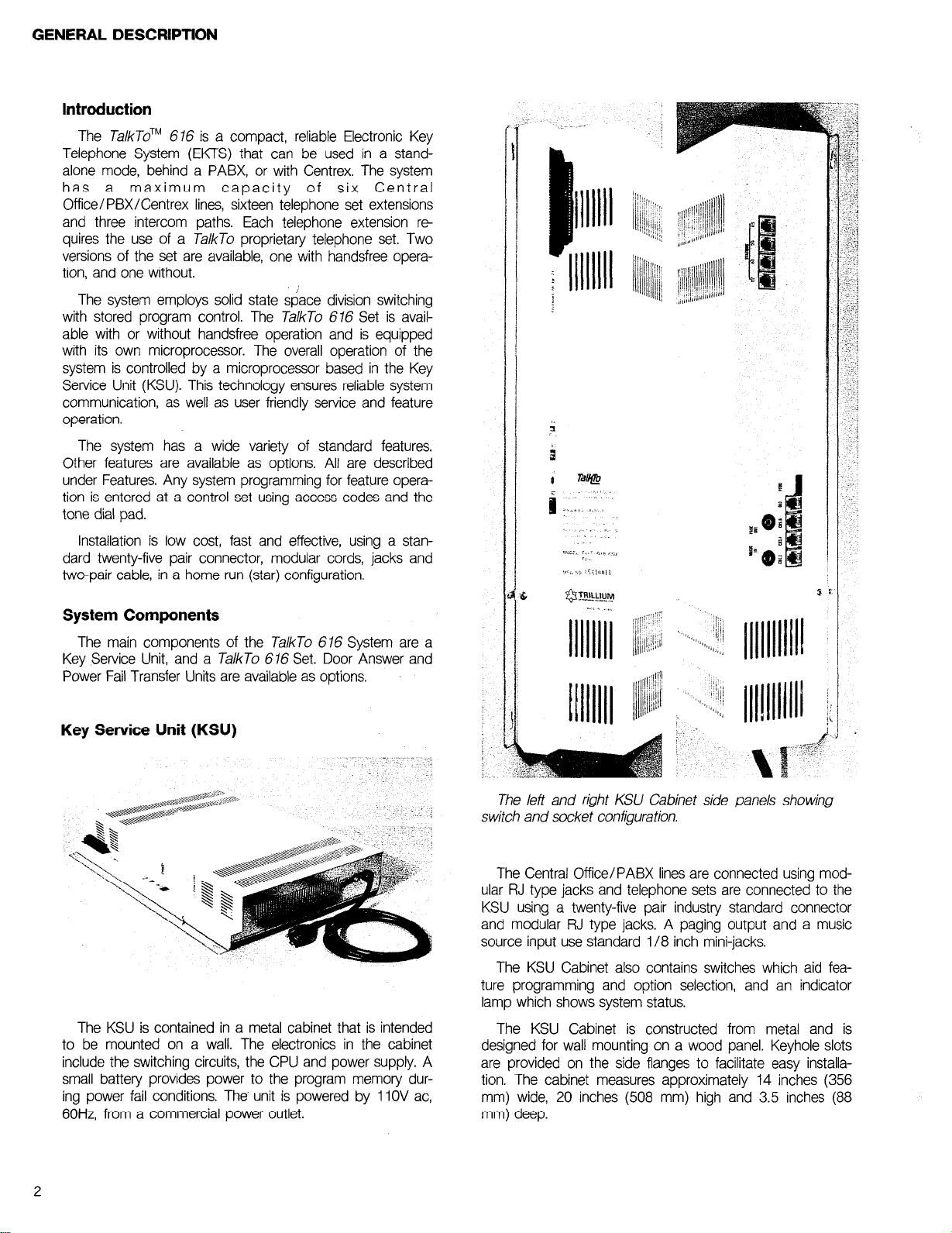
Key Service Unit (KSU)
The KSU is contained in a metal cabinet that is intended
to be mounted on a wall. The electronics in the cabinet
include the switching circuits, the CPU and power supply. A
small battery provides power to the program memory dur-
ing power fail conditions. The’ unit is powered by 11OV ac,
60Hz, from a commercial power outlet.
The left and right KSU Cabinet side panels showing
switch and socket configuration.
The Central Office/PABX lines are connected using modular RJ type jacks and telephone sets are connected to the
KSU using a twenty-five pair industry standard connector
and modular RJ type jacks. A paging output and a music
source input use standard l/8 inch mini-jacks.
The KSU Cabinet also contains switches which aid fea-
ture programming and option selection, and an indicator
lamp which shows system status.
The KSU Cabinet is constructed from metal and is
designed for wall mounting on a wood panel. Keyhole slots
are provided on the side flanges to facilitate easy installation. The cabinet measures approximately 14 inches (356
mm) wide, 20 inches (508 mm) high and 3.5 inches (88
mm) deep.
2
Page 5

GENERAL DESCRIPTION
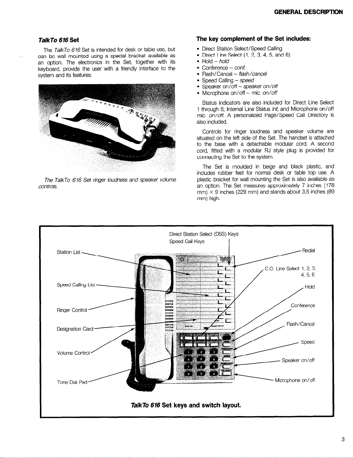
TalkTo 616 Set
The TalkTo 676 Set is intended for desk or table use, but
can be wall mounted using a special bracket available as
an option. The electronics in the Set, together with its
keyboard, provide the user with a friendly interface to the
system and its features:
The TalkTo 616 Set ringer loudness and speaker volume
controls.
The key complement of the Set includes:
l
Direct Station Select/Speed Calling
l
Direct Line Select (1, 2, 3, 4, 5, and 6)
l
Hold - hold
l
Conference - conf
l
Flash/Cancel - flash/cancel
l
Speed Calling - speed
l
Speaker on/off - speaker on/off
l
Microphone on/off - mic. on/olY
Status indicators are also included for Direct Line Select
1 through 6; Internal Line Status int; and Microphone on/off
mic. on/off. A personalized Page/Speed Call Directory is
also included.
Controls for ringer loudness and speaker volume are
situated on the left side of the Set. The handset is attached
to the base with a detachable modular cord. A second
cord, fitted with a modular RJ style plug is provided for
connecting the Set to the system.
The Set is moulded in beige and black plastic, and
includes rubber feet for normal desk or table top use. A
plastic bracket for wall mounting the Set is also available as
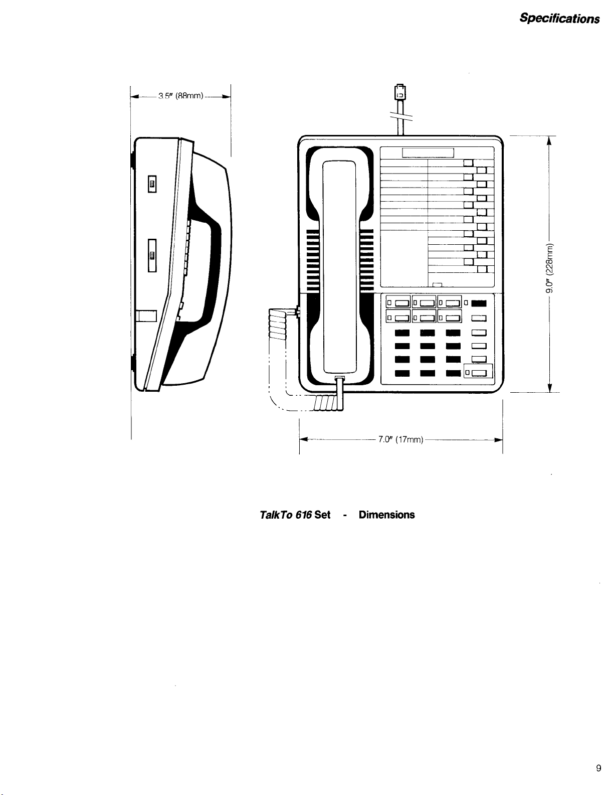
an option. The Set measures approximately 7 inches (178
mm) x 9 inches (229 mm) and stands about 3.5 inches (89
mm) high.
Station List -
Speed Calling List -
Ringer Control 1
Designation Card 71
Volume Control A f
Tone Dial Pad’
Direct Station Select (DSS) Keys
Speed Call Keys
I
I
1 Redial
Hold
Microphone on/off
TakTo 676 Set keys and switch layout.
Page 6
GENERAL DESCRIPTtDN
. . .
TalkTo 616 Set
The TalkTo 616 Set is intended for desk or table use, but
can be wall mounted using a special bracket available as
an option. The electronics in the Set, together with its
keyboard, provide the user with a friendly interface to the
system and its features:
The TalkTo 616 Set ringer loudness and speaker volume
controls.
The key complement of the Set includes:
l
Direct Station Select/Speed Calling
l
Direct Line Select (1, 2, 3, 4, 5, and 6)
l
Hold - ho/d
l
Conference - conf:
l
Flash/Cancel - flash/cancel
l
Speed Calling - speed
l
Speaker on/off - speaker on/off
l
Microphone on/off - mic. on/off
Status indicators are also included for Direct Line Select
1 through 6; Internal Line Status int, and Microphone on/off
mic. on/off. A personalized Page/Speed Call Directory is
also included.
Controls for ringer loudness and speaker volume are
situated on the left side of the Set. The handset is attached
to the base with a detachable modular cord. A second
cord, fitted with a modular RJ style plug is provided for
connecting the Set to the system.
The Set is moulded in beige and black plastic, and
includes rubber feet for normal desk or table top use. A
plastic bracket for wall mounting the Set is also available as
an option. The Set measures approximately 7 inches (178
mm) x 9 inches (229 mm) and stands about 3.5 inches (89
mm) high.
Station List -
Speed Calling List
Ringer Control j
Designation Card
Volume Control
Tone Dial Pad’
/I
Direct Station Select (DSS) Keys
Speed Call Keys
I
, Redial
Hold
/
q
M Speaker on/off
A Microphone on/off
TalkTo 676 Set keys and switch layout.
3
Page 7
GENERAL DESCRIPTION
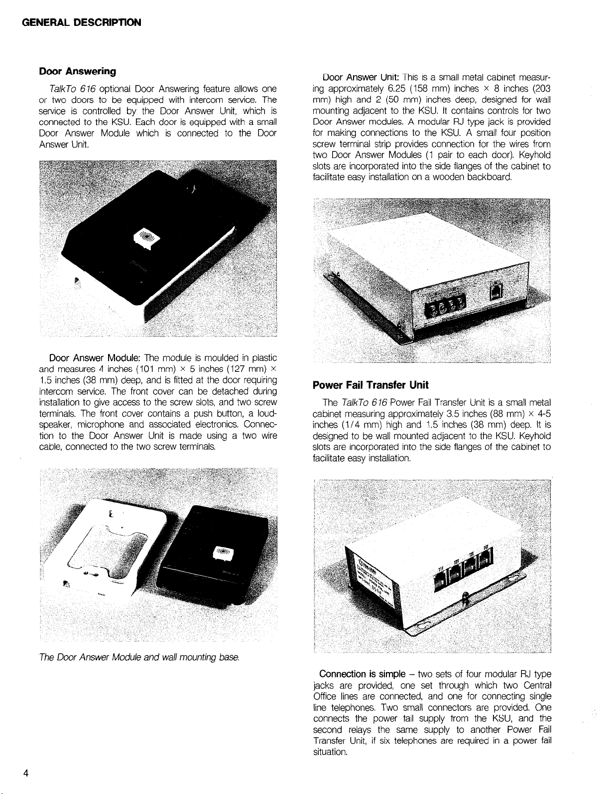
Door Answering
TalkTo 616 optional Door Answering feature allows one
or two doors to be equipped with intercom service. The
service is controlled by the Door Answer Unit, which is
connected to the KSU. Each door is equipped with a small
Door Answer Module which is connected to the Door
Answer Unit.
Door Answer Module: The module is moulded in plastic
and measures 4 inches (101 mm) X 5 inches (127 mm) X
1.5 inches (38 mm) deep, and is fitted at the door requiring
intercom service. The front cover can be detached during
installation to give access to the screw slots, and two screw
terminals. The front cover contains a push button, a loudspeaker, microphone and associated electronics. Connection to the Door Answer Unit is made using a two wire
cable, connected to the two screw terminals.
Door Answer Unit: This is a small metal cabinet measur-
ing approximately 6.25 (158 mm) inches x 8 inches (203
mm) high and 2 (50 mm) inches deep, designed for wall
mounting adjacent to the KSU. It contains controls for two
Door Answer modules. A modular RJ type jack is provided
for making connections to the KSU. A small four position
screw terminal strip provides connection for the wires from
two Door Answer Modules (1 pair to each door). Keyhold
slots are incorporated into the side flanges of the cabinet to
facilitate easy installation on a wooden backboard.
Power Fail Transfer Unit
The T&To 616 Power Fail Transfer Unit is a small metal
cabinet measuring approximately 3.5 inches (88 mm) x 4-5
inches (l/4 mm) high and 1.5 inches (38 mm) deep. It is
designed to be wall mounted adjacent to the KSU. Keyhold
slots are incorporated into the side flanges of the cabinet to
facilitate easy installation.
The Door Answer Module and wall mounting base.
4
Connection is simple - two sets of four modular RJ type
jacks are provided, one set through which two Central
Office lines are connected, and one for connecting single
line telephones. Two small connectors are provided. One
connects the power fail supply from the KSU, and the
second relays the same supply to another Power Fail
Transfer Unit, if six telephones are required in a power fail
situation.
Page 8
FEATURES
The T&To 676 system is equipped with a wide range of
standard features. The only options are:
TalkTo 676 Set, which is available with or without hands-
free operation.
Door Answering, which requires the addition of a Door
Answer Unit, and up to two Door Answer Modules.
Power Fail Transfer, which requires the addition of Power
Fail Transfer Units and up to six regular telephones.
X X X
Standard Features
Add-On Conference
The TalkTo 676 system provides 3 party conferencing.
The conference may include 3 TalkTo stations, 2 TalkTo
stations plus 1 Central Office (CO) line, or 1 TalkTo station
plus 2 CO lines.
All Page
Each TalkTo 616 Set user can make a paging announce-
ment, using a single key, through the speakers of all other
Sets. An alert tone precedes the announcement.
Discriminating Ringing
Allows a Set user to distinguish between incoming CO
calls and intercom calls.
Do Not Disturb
Disallows internal calls from ringing at a TalkTo 616 Set.
This feature is enabled when the Set user dials *9. To
return the Set to normal, dial *CS,again. In the DND mode,
the user may use the Set for outgoing calls in the normal
manner.
I
Exclusive Hold with Indication
A CO call may be placed on exclusive hold (by pressing
hold key twice). This prohibits the call from being retrieved
from any other Sets. With exclusive hold, the CO line
indicator has a very fast distinctive flash rate.
External Loudspeaker Paging
A connector provides an interface to an external paging
system. If connection is made, all TalkTo 676 Sets are
allowed access to a customer provided external paging
system. After dialing the access code (59) the Set user
hears a short tone indicating that the TalkTo 6 76 Set is now
connected to the paging equipment, and the paging announcement can begin.
Automatic Intercom Path Selection
The TalkTo 616 System has 3 intercom paths, one of
which is selected automatically each time a request for
intercom service is initiated.
Automatic Privacy
Prevents all other users from entering or listening to your
CO or intercom call.
Background Music
When a TalkTo 676 Set is not in use, the user may
choose to listen to music. To enable this feature, dial Jc4.
Music is heard through the Set’s speaker. A customer
provided music source must be connected to the music
interface jack.
Call Hold
Allows a Set user to place a call on hold, go on-hook, or
use the TalkTo Set for another call. This call can be picked
up at any other Set. When the call is placed on hold, the
Ta/kTo Set user receives a visual indication (flashing) for the
line on hold.
Direct Station Selection
Each TalkTo 676 Set is equipped with 15 direct station
select keys. When a DSS key is pressed the system autc-
matically dials the number of the Set to which the key is
assigned.
Flash/Cancel Key
This key may be programmed as a calibrated flash hook
or as cancel. As flash, each time the key is pressed, a
timed flash will be sent to the CO or PABX, to access
custom calling features. This calibrated flash may be programmed for 250ms, 500ms IOOOms or 2000ms.
As cancel, an external call may be terminated by pressing the cancel key without replacing the handset in the
cradle.
Flexible Ringing Assignment
Each CO line may be programmed to ring all TalkTo 676
Sets, or selected Sets.
Hold Recall
A Set user that has placed a call on hold, will receive an
audible signal (from the Set’s speaker), after a programmable interval (1, 2, 3 or unlimited minutes).
I-Hold Indication
The indicator for the CO line placed on hold at your Set
will have a faster flash rate to those lines held at other Sets.
My-Line Indication
Indication that allows the user to distinguish between the
user’s line and other lines. The indicator for the CO line in
use gives a winking flash.
Page 9
FEATURES
Last Number Redial
Allows last number dialed at each TalkTo 616 Set to be
stored and later redialed automatically upon request by
pressing the redial key.
Meet-Me Answer
Any
TalkTo
access code - Jc 1.
616 Set can answer all page by dialing the
Microphone On/Off
The mic.
microphone at any time.
on/of7
switch allows the’ user to disable the
Multi-Line Pickup and Transfer
All Sets may originate and receive CO calls, and may
initiate transfers.
Music On-Hold (MOH)
When a CO call is placed on hold, the caller hears music
provided an external music source is connected to the
music input jack.
Music: On-Hold/Background Interface
A i/8 inch mini-jack is provided on the KSU for connecting an external music source to provide Music On-Hold and
Background music for the system.
Night Transfer
When in the night mode, all C.O. calls are routed to
selected Sets programmed for this purpose. To place sys-
tem in the night mode, dial *9 from the control Set
(number 10). To remove from night mode, dial 368 from the
control Set.
On-Hook Dialing
All
TalkTo
on-hook.
676 Set users may dial with the handset
Outgoing Call Restriction
Each
TalkTo
outgoing calls.
616 Set may be programmed to disallow
Paging - Individual (Tone First)
A voice call can be made to an individual Set and is
preceded by an alert tone. Answer back is completely
handsfree, and the conversation is fully duplex. At a
616 Set without the handsfree option, the call is originated
using the handset. If the Set is equipped with the handsfree
option, the call can be originated using the handset or
microphone.
TalkTo
PBX Pause
When the
the digits 7, 8, 9, and 0 may be programmed to initiate a
three second pause when dialed as the first digit. This
pause allows second dial tone to be returned when dialing
out to a CO line.
TalkTo
616 system is used behind a PABX,
Private CO Line
CO line number 1 can be made exclusive to one Set only
by programming. The private CO line cannot be answered
or accessed from any other Set.
Speakerphone
The
TalkTo
616 Set (handsfree model) provides the user
with the convenience of originating or receiving calls and
talking, without having to use the handset.
Speaker Volume Control
A slider controls the volume of the speaker output of the
Set.
Speed Calling Common
All Sets have access to 40 common speed call numbers,
each up to 16 digits maximum, using access codes. Programming of numbers is simple, using the Control Set
(number 10). A mixture of speed call and manually dialed
numbers can be made. Two speed call numbers may be
linked together.
Speed Calling - Private
Each
TalkTo
616 Set has access to 10 private speed call
numbers, each up to 16 digits maximum, using a single key.
Programming of numbers is simple, using the individual Set.
Access codes to PABX custom features may be stored in
place of directory numbers. Mixtures of speed call and
manually dialed numbers can be made. Two speed
numbers may be linked together.
Toll Restriction
Each
TalkTo
toll calls. The system will restrict on O/l for the first dialed
digit, and if more than 7 digits are dialed.
616 Set may be programmed to disallow
.
Tone Ringer Control
A 3-position slide switch controls the loudness of the tone
ringer.
Optional Features
Door Answering
The addition of a Door Answer Unit, and two Door
Answer Modules provides intercom service at the two doors
where the modules are installed.
Pressing the button on the door module causes a distinc-
tive tone to be heard at all the
Lifting the handset and depressing CO Line Key number 6
allows the Set user to converse with the person at the door.
Power Failure Transfer (PFT)
One Power Fail Transfer unit provides PFT for 4 CO lines,
provided four single line telephones are also installed. If
power to the KSU fails, the 4 CO lines will be automatically
switched to the 4 industry standard telephones. A second
unit may be added to provide another 2 power fail pro
tected telephones.
TalkTo
616 Set speakers.
call
6
Page 10
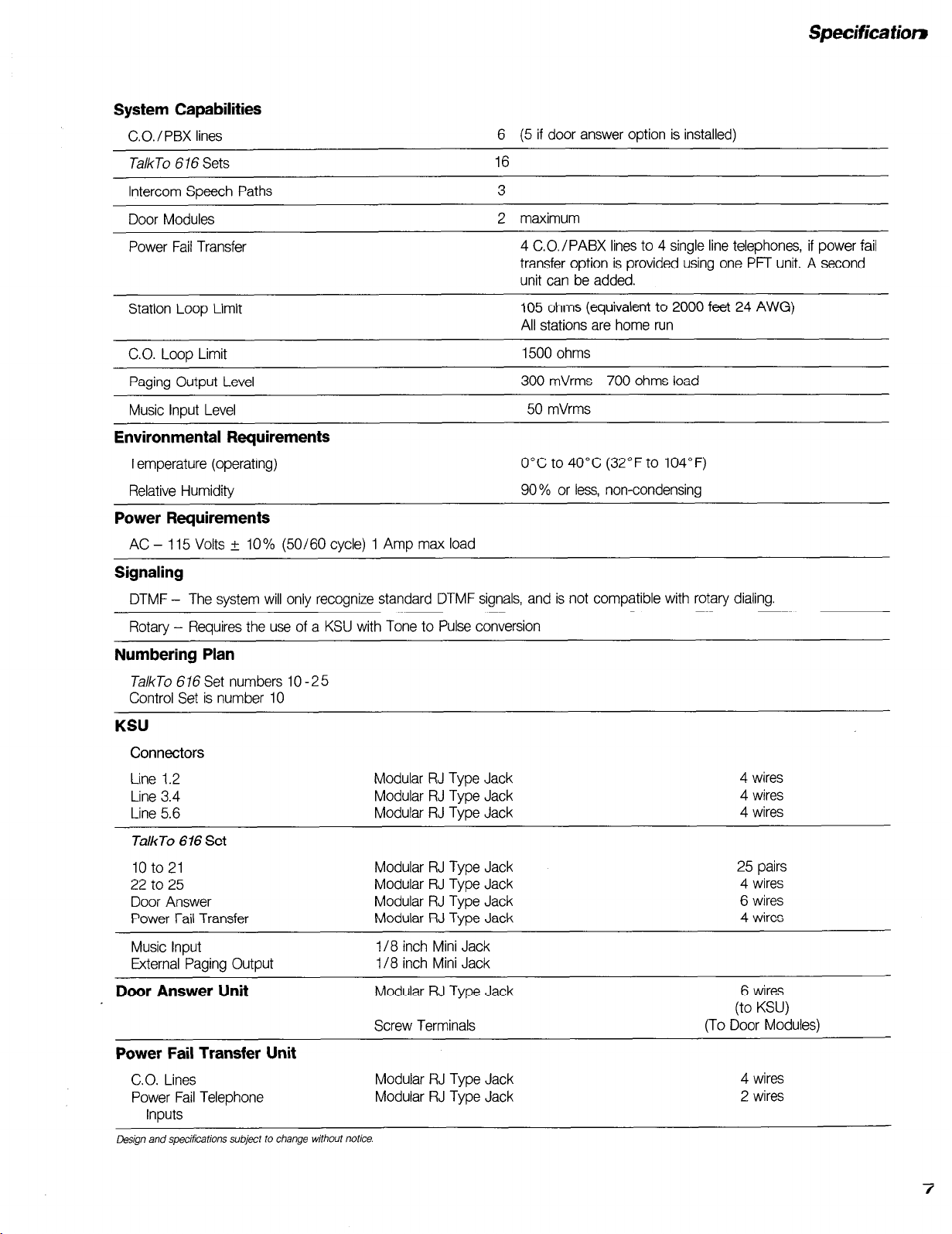
System Capabilities
C.O. / PBX lines
6 (5 if door answer option is installed)
TalkTo 6 16 Sets
Intercom Speech Paths 3
Door Modules
Power Fail Transfer
Station Loop Limit
C.O. Loop Limit
Paging Output Level
Music input Level
16
2 maximum
4 C.O./PABX lines to 4 single line telephones, if power fail
transfer option is provided using one PFT unit. A second
unit can be added.
105 ohms (equivalent to 2000 feet 24 AWG)
All stations are home run
1500 ohms
300 mVrms 700 ohms load
50 mVrms
Environmental Requirements
Temperature (operating)
Relative Humidity
0°C to 40°C (32°F to 104°F)
90% or less, non-condensing
Power Requirements
AC - 115 Volts i IO % (50/60 cycle) 1 Amp max load
Signaling
DTMF - The system will only recognize standard DTMF signals, and is not compatible with rotary dialing.
Rotary - Requires the use of a KSU with Tone to Pulse conversion
Numbering Plan
TalkTo 616 Set numbers 10 -25
Control Set is number 10
KSU
Connectors
Line 1.2
Line 3.4
Line 5.6
TalkTo 616 Set
10 to 21
22 to 25
Door Answer
Power Fail Transfer
Music Input
External Paging Output
Door Answer Unit
Modular RJ Type Jack
Modular RJ Type Jack
Modular RJ Type Jack
Modular RJ Type Jack
Modular RJ Type Jack
Modular RJ Type Jack
Modular RJ Type Jack
l/8 inch Mini Jack
l/8 inch Mini Jack
Modular RJ Type Jack
Screw Terminals
Power Fail Transfer Unit
CO. Lines
Power Fail Telephone
Inputs
Design and specifications subject to change without notice.
Modular RJ Type Jack
Modular RJ Type Jack
4 wires
4 wires
4 wires
25 pairs
4 wires
6 wires
4 wires
6 wires
(to KSU)
(To Door Modules)
4 wires
2 wires
7
Page 11
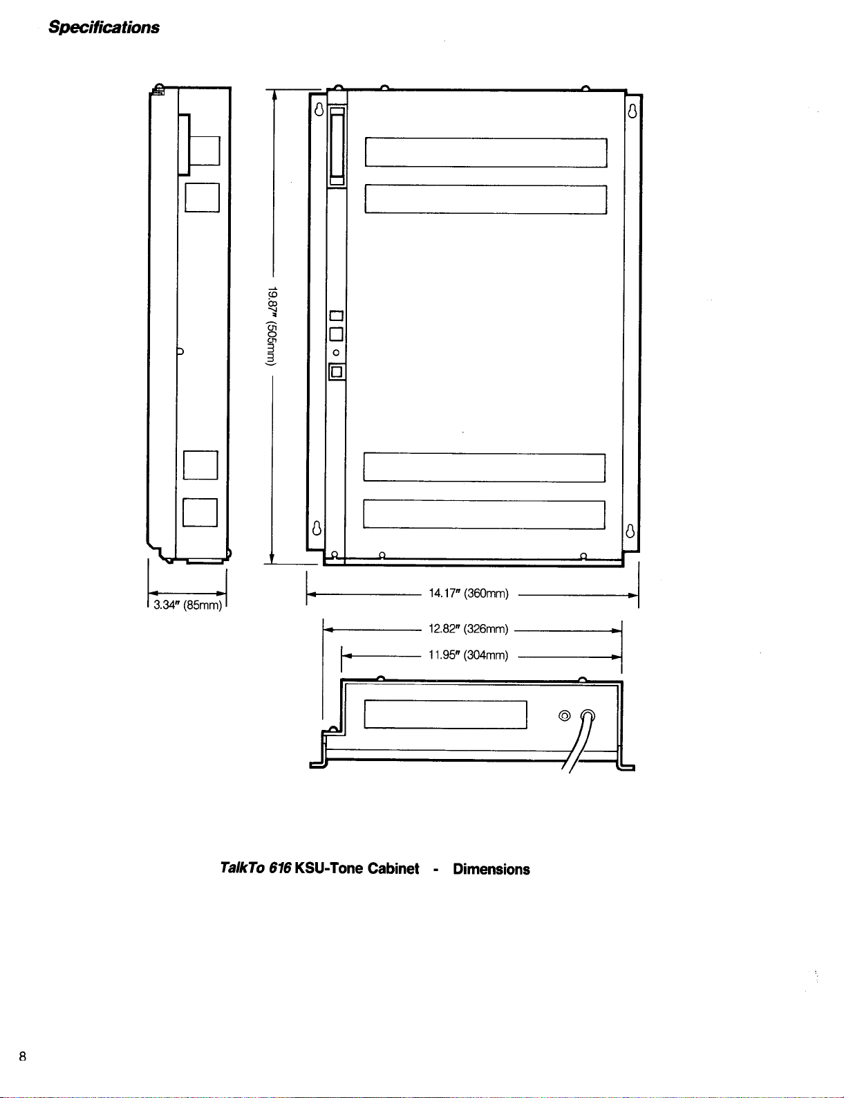
Specifications
b
I
,
El
El
I 4
I I
I I
13.34”
TalkTo 616 KS&Tone Cabinet - Dimensions
8
Page 12
L
Specifications
3.5” (88mm)
I
i.
+.-----
7.0” (17mm) ~
I I
I
TalkTo 616
- Dimensions
Set
9
Page 13
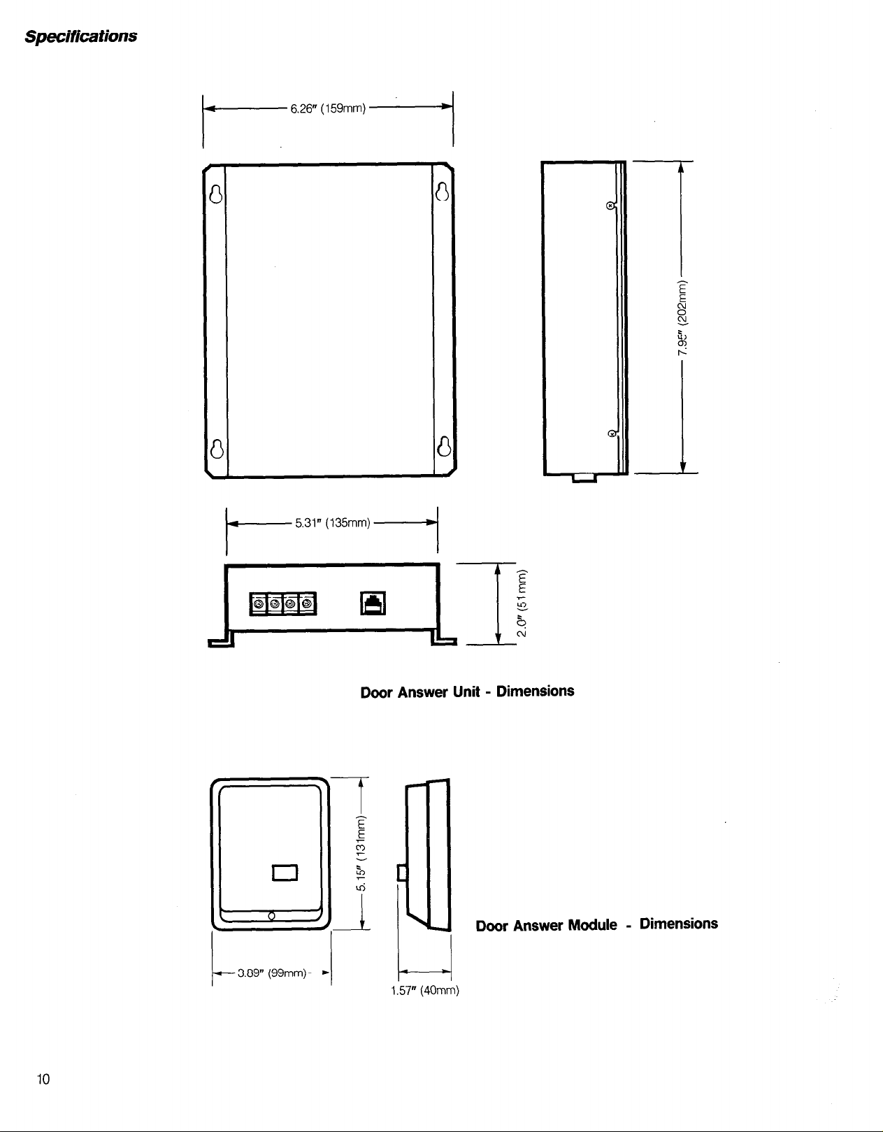
Specifications
- 6.26” (159mm)
-I
- 5.31” (135mm)
I-
Door Answer Unit - Dimensions
I
1 Door Answer Module - Dimensions
10
b 3.89” (99mm)q
1.57” (40mm)
Page 14

- 3.54” (90mm) -
Specifications
2.63” (67mm)
I---
Power Fail Transfer Unit - Dimensions
Page 15

ORDERING INFORMATlON
Each T&To 6 16 system requires the following:
l
One Key Service Unit.
l
A number of TalkTo 616 Sets, up to 16 maximum.
l
One Door Answering Unit (optional).
l
One or two Door Answer Modules (optional).
l
One Power Fail Transfer Unit (optional).
Description
TalkTo 616
TalkTo 616 KSU (Rotary or Tone CO. lines)
TalkTo 6 16 Set
TalkTo 6 16 Handsfree Set
Door Answer Unit
Door Answer Module
Power Fail Transfer Unit (For 4 C.O. lines)
TalkTo Set Wall Mount Bracket
KSU (Tone C.O. lines)
Part No.
90-0050
90-0054
90-0056
go-005
go-0057
90-0058
90-0052
go-0059
1
Key Service Units
If the C.O. service is strictly tone (DTMF) only, order KSU
part number 90-0050. This unit will not recognize rotary
dialing.
If the CO. service is rotary dialing, order KSU part
number 90-0054.
TalkTo 616 Set
All 616 system stations must be equipped with TalkTo
676 Sets. There are two versions of the set, one with
handsfree operation, and one without. The number of sets
may not exceed eight total. Part numbers for the sets are:
l
TalkTo 676 Set 90-0056
l
TalkTo 616 Set 90-0051
(with “handsfree” operation)
Door Answering Option
Door answering option allows intercom service to two
doors to be added to the basic 616 system. If the option is
required, order one Door Answer Unit part number
90-0057, and one or two Door Answer Modules, part
number 90-0058. The number of Door Answer Modules
depends on whether service to one or two doors is required.
Power Fail Transfer Option
This option allows single line service for the four CO.
lines, in the event of a power failure to the KSU. Few
industry standard telephone sets are required for this option
and are not supplied with the PFT unit.
A second PFT unit can be connected to the first, to
provide power fail service to another two telephones which
are not supplied with the PFT option.
Miscellaneous Parts
The do-it-yourself homeowner who wishes to install the
system, will require a number of Modular Telephone Extension Cords to complete the hook-up of the telephone sets
and options. These are readily available through any retail
store selling telephones and accessories.
Disclaimer
There are no warranties which extend beyond the description on the face hereof. Manufacturer disclaims any
implied warranty of merchantability or fitness for a
particular purpose.
12
Page 16

INSTALLATiON PROCEDURES
TRSLLS(JM
telephone systems
Page 17

Page 18

Table of Contents
FCC Requirements and Warnings . . . . . . . . . . . . . . . . . . . . . . . . . . . . . . . . . . . 2
Introduction
Preparation. . .
Pre-installation Requirements . . . . . . . . . . . . . . . . . . . . . . . . . . . . . . . . . . . . . . . . 4
Installation
KSU Installation..
Station Wiring Method 1.
Station Wiring Method 2..
Central Office/PBAX Line Connection
Music Input
Paging Output..
Door Answer Option ..................... .
Power Failure Transfer Option
System Programming
Preparation..
Programming Mode
Initial Programming..
Reprogramming..
Feature Programming..
Individual Feature Programming
Hold Recall - Pulse Duration - Flash Cancel ......... 19
C.O./PABX
Incoming Call Only - By Line.. ............................... .20
Outgoing
Night Transfer and Private Lines - By Station.........2 0
Flexible Ringing - By Station and CO. Line.. ......... .21
Calibrated
Pause on Number.. .................................................. .21
Operating
Speed Calling - Common Numbers,
Programming.. ........................................................... 21
. . . . . . . . . . . . . . . . . . . . . . . . . . . . . . . . . . . . . . . . . . . . . . . . . . . . . . . . . . . .
.................................
............................................. .
......................................... .10
...............................................................
......................................................... .ll
.................................... .13
.............................................................. .18
..................................................
................................................. .18
...................................................... .18
............................................. .18
Line..
...................................................... .19
Call
Restriction - By Station.. .................. .20
Flash/Cancel
Mode
........................................................ .21
............................................ .21
.._ ......................
......................... 10
........................... .ll
.I1
.18
4
5
Troubleshooting. . . . . . . . . . . . . . . . . . . . . . . . . . . . . . . . . . . . . . . . . . . . . . .
23
Page 19

FCC Requirements
The Federal Communications Commission (FCC)
has established rules which permit the Trillium Telephone
Systems Talk75 616 Electronic Key Telephone System to be
directly connected to the telephone network. A jack is provided by the telephone company. Jacks for this type of
customer provided equipment will not be provided on party lines or coin lines.
If the system is malfunctioning, it may also be causing harm to the telephone network; the system should be
disconnected until the source of the problem can be determined and until repair has been made. If this is not done,
the telephone company may temporarily disconnect
service.
The telephone company may make changes in its
technical operations and procedures; if such changes
affect the compatibility or use of the system, the telephone
company is required to give adequate notice of the
changes.
equipment causes interference to radio or television recep-
tion, which can be determined by unplugging the
Talk75
676 Key Service Unit (KSU), from electrical power, the user
is encouraged to try to correct the interferences by one
of the following measures:
l
Re-orient the receiving antenna.
l
Relocate
l
Move
TalkTo
676 units with respect to the receiver.
TalkTo
676 units away from the receiver
If necessary, the user should consult the supplier
or an experienced radio/television technician for additional
suggestions. The user may find the following booklet,
prepared by the Federal Communications Commission,
helpful: “How to Identify and Resolve Radio-n/ Interference
Problems’! This booklet is available from the U.S. Govern-
ment Printing Office, Washington, DC 20402, Stock No.
004-000-00345-4,
Service Requirements
In the event of equipment malfunction, all repairs
will be implemented by Trillium Telephone Systems. It is
the responsibility of users requiring service to report the
need for service to Trillium Telephone Systems or to one
of their authorized agents.
Company Notification
Before connecting the TalkTo 616 Electronic Key
Telephone System to the telephone network, the telephone
company must be provided with the following:
l
Your telephone number
l
The FCC Registration Number
l
The Ringer Equivalence Number
l
The USOC jacks required.
The FCC Registration Number, and the Ringer
Equivalence are indicated on the System label.
The jacks for the system are:
l
Lines one and two - RJ14C.
l
Line three and four - RJ14C.
l
Lines five and six - RJ14C.
Warnings
Radio Frequency Energy
The
TalkTo
616 Electronic Key Telephone System
generates and uses radio frequency energy and if not
installed and used properly, that is, in strict accordance
with manufacturer’s instructions, may cause interference
to radio and television reception. It has been type tested
and found to comply with the limits for a Class B computing device in accordance with the specifications in Subpart I of Part 15 of FCC rules which are designed to provide reasonable protection against such interference in a
residential installation. However, there is no guarantee that
interference will not occur in a particular installation. If this
Hearing Aid Compatibility
‘This telephone is not hearing aid-compatible as is
defined in Section 68.316 of Part 68 FCC Rules. As such,
the FCC rules prohibit the use of this telephone in the
following locations:
a) Coin telephones.
telephones whether
semi-public location
club).
b) Emergency use telephones. Telephones “provided for
emergency use” include the following:
1) Telephones in places where a person with impaired
hearing might be isolated in an emergency, including but
not limited to, elevators, automobiles, railroad or subway
tunnels, and highways.
2) Telephones specifically installed to alert emergency
authorities, including, but not limited to, police or fire
departments or medical assistance personnel.
3) Telephones needed to signal life-threatening or
emergency situations in confined settings, including, but
not limited to, rooms in hospitals, residential health care
facilities for senior citizens convalescent homes, and
prisons. A telephone is not needed to signal life-threatening
or emergency situations if an alternative means of signalling such a situation is available.
c) Telephones frequently needed by the hearing impaired
1) Any telephone on which calls may only be paid for by
credit card or other pre-arranged credit. Each such
telephone must be hearing aid-compatible unless a hear-
ing aid-compatible coin-operated telephone providing
similar services is nearby and readily available.
All new and existing coin-operated
located on public property or in a
(e.g. drugstore, gas station, private
2
Page 20

2) Any telephone made available at the work station of a
hearing-impaired employee for use by that employee in
his or her employment duty. An employee’s “work station”
is defined as the location within a workplace where that
employee is usually found in the course of his or her
employment duties.
3) Any telephone, including internal extensions and
telephones restricted to local calling areas, made available
for use by the public in places of business or buildings
in which visits by the public are reasonably expected.
Examples include, but are not limited to, telephones
located in lobbies of hotels or apartment buildings;
telephones in stores, which are used by patrons to order
merchandise: telephones in public transportation terminals
which are used to call taxis or to reserve rental
automobiles.
4) Any telephone in a hotel or motel room. Provided that,
if at least ten percent of the rooms in a hotel or motel are
equipped to accommodate a hearing impaired customer,
the hotel or motel need not purchase or install a compat-
ible telephone when it replaces a telephone. A room is
equipped to accommodate a hearing impaired customer
if (1) it contains a permanently installed hearing aid-
compatible telephone; or (2) it contains a telephone which
will accept a plug-in hearing aid-compatible handset,
which shall be provided to the hearing impaired customer
by the hotel or motel; or (3) the room contains a jack into
which a hearing aid-compatible telephone provided to the
customer by the hotel or motel may be plugged (i.e., in
addition to a permanently installed telephone which is not
hearing aid-compatible).
.::
If fewer than ten percent of the rooms in a hotel or motel
are hearing aid-compatible, when replacing a telephone
the hotel or motel must, until the ten percent minimum is
reached: (1) replace it with a hearing aid-compatible
telephone, or (2) procure and maintain a plug-in hearing
aid-compatible telephone handset which it will provide to
a hearing impaired customer upon request at check-in.
5) Any telephone in the locations listed in (b) (3) in which
an alternative means of signalling a life-threatening or
emergency situation is not available.
* * *
Page 21

INSTALLATION
Introduction
This manual details the procedures to install and
program the TalkTo 676 Electronic Key Telephone System.
A section on Troubleshooting is also included.
Installation is easy, and can be carried out by a certified installer, using standard cable runs and modular
jacks; or if so desired by the end-user, using standard
modular telephone line cords, extension cords, and
adapters.
Preparation
The installer should ensure that the area chosen
to mount the KSU is:
l
Clean, dry and well ventilated. The temperature should
be between O” and 40% (32O and 104Y). The relative
humidity should be 90% or less, and be non-condensing.
l
Within seven feet of the C.O./PABX line terminations.
l
Within close proximity to the station terminations (in the
case where outdated equipment is being replaced). The
distance to each station is limited to a maximum of 2000
feet (609 meters) when 24 AWG wire is used.
The TalkTo 616
use, but can be wall mounted using a special bracket
available as an option.
Set is intended for desk or tab/e
l
Within five feet (1.5 meters) of a
11
OV ac 60Hz three-
wire dedicated unswitched power outlet.
Station wiring should be standard two pair twisted
communication cable, 24 AWG. It is assumed that the C.O.
lines are terminated at RJ style modular jacks.
Pre-installation Requirements
Unpack the system and check that all items conform to the list of parts ordered. Make sure that the
customer’s feature requirements have been documented
on a Customer Feature Selection form.
Description
TalkTo 676
(KSU) (DTMF)
TalkTo 676
(KSU) (Rotary or DTMF)
TalkTo 616
TalkTo 616
TalkTo
TalkTo
TalkTo
a concrete or masonry wall, a plywood backboard should
be provided.
vided for the dedicated power outlet, A suitable device is
the TII Model 428 plug-in protector or equivalent.
Key Service Unit
Key Service Unit
Set
Set (Handsfree)
Door Answer Unit
Door Module
Power Fail Transfer Unit
If the Key Service Unit (KSU) is to be mounted on
It is recommended that a surge protector be pro-
Part Number
90-0050
go-0054
90-0056
90-0051
go-0057
90-0058
go-0052
The Key Service Unit (KSU) is contained in a metal
cabinet and should be wall mounted.
‘L-J
The Door Answer Module is moulded in plastic,
measures 4 inches x 5 inches, and is fitted at the door
requiring intercom service.
,
.’ -I
.i
.3
4
Page 22

The Door Answer Unit measures 6.25 inches x 8
inches and should be wall mounted adjacent to the
KSU.
INSTALLATION
KSU’ Installation
The KSU contains no user adjustable controls or
parts. All switches used during programming are accessible at the exterior of the KSU. An indicator on the left
side of the KSU flashes when the system is up and
running.
The 11OV ac three-wire out/et should be
dedicated to the KSU.
trical breaker for this outlet should be equipped with a lock-
ing clip, or marked with label, to prevent accidental shutdown of the system. A surge protector should be installed at the 11OV ac outlet.
A suitable unit is the TII Model 428, plug-in power
line surge protector. Install the protector in accordance with
the manufacturers instructions.
The KSU is intended for wall mounting only. If a
backboard is to be used, start the KSU installation by
mounting the backboard on the wall. Then:
l
Mark the position of the four KSU mounting screws on
the backboard.
l
Drive in four screws (supplied with the KSU) to within
l/8 inch of the board surface.
l
Using the four keyhole slots in the KSU cabinet, hang
the unit on the four screws.
l
Tighten the screws to secure the KSU to the backboard.
At the service panel, the elec-
Connect the ground lug of the KSU, to a metal cold
water pipe or ground stake, using 12 AWG (2.64mm
diameter) or heavier, copper wire. If a cold water pipe is
‘,
used, ensure that the continuity to ground is not broken
by the use of plastic pipe. If a ground stake is used for
.-
.” _-.
The Power Fail Transfer Unit measures 3.5 inches x
4.5 inches and should be wall mounted adjacent to
the KSU.
this purpose, it must be properly-installed in accordance
with the local electrical code.
Caution: Failure to properly ground the KSU may
affect the system warranty
Carry out a preliminary check of the KSU opera-
* * *
Ins talla tion
.;
.:
The TalkTo 676 System is easily installed using the
following procedures:
l
KSU installation
l
Station Wiring (2 methods)
l
Music Input
l
Paging Output
l
Door Answer Option
l
Power Fail Transfer Option
tion as follows:
l
Set the switch,
l
Set the Switches,
l
Connect the KSU power cord to the surge protector
Battery,
Program 1
to
On.
and 2, to Off.
previously installed at the 11OV ac power outlet.
l
Status indicator
lamp should flash.
This indicates that the KSU is operative.
To prevent accidental damage to the KSU while the
system wiring is being installed, remove the power from
the KSU as follows:
l
Set the switch,
l
Disconnect the power cord from the surge protector.
Battery,
to OH.
5
Page 23

INSTALLATION
Stations 10 - 21 -
Program 1
Program 2 1
Not Used -
Battery -
Status Indicator -
Reset Push Button’
a
14.17”
(36Omm)~~
__--- 13.38” (340mm) -
-
Stations
22 - 25
II-
Page Out
/
3
1
- PFUC
- Door
- CO 5.6
- co 3.4
- co
1.2
\
I
\ Music In
-
_
I
L
El
R
n
n
Z’
*
4
12.82” (326mm) -4 \
i 1.95” (304mm)pdjlound Lug
TalkTo 616
6
t
KSU Cabinet - Dimensions
Page 24

INSTALLATION
Station Wiring - Method 1
This method uses 25 pair standard cabling and a
66 Type Punch Down Block, to connect 12 stations, and
4 modular line cords and half 66 Type Punch Down Block
to connect the remaining 4 stations. Cable runs to the station locations use communication cable (2 pair 24 AWG),
625 type four-wire jacks, and modular line cords.
Adjacent to the left hand side of the KSU, install the
66 Type Punch Down Block (S66-M&50/? of similar).
Prepare a-25 pair cable of appropriate length with a jack
on the KSU end and a plug at the Punch Down Block
end. (If a
be required at the block). Connect the 2.5 pair cable to
the KSU and 66 type block (see Method 1 Wiring Table).
Run communication cable to each station location, and
terminate each run with a 625 type modular jack. Install
each set with a modular line cord (one is supplied with
each set).
half 66 Type Punch Down Block (S66-M4-25TLM-A) or
similar. Prepare four short 4-wire modular line cords of appropriate length, with a plug at both ends. Plug the cords
into the KSU
jacks on the Punch Down Block. Observe the correct sta-
tion connections at block. Run communication cable to
each set location, and terminate each run with a 625 type
modular jack. Install each set using a modular line cord
(one is supplied with each set).
C.O./PABX lines.
Typical 625 type jack showing wiring connections.
66M7-50
block is used, installer cut down will
Adjacent to the right hand side of the KSU, install the
(STA22-STA26),
and into the four modular
You are now ready to connect the KSU to the
Method 1 Wiring Table
Pin
Lead
Desig.
1vT
26
1 1VR
27 1DT
1DR
2
28 2vr
2VR
3
2DT
29
4 2DR
3V-r
30
5 3VR
3DT
31
6 3DR
4VT
32
4VR
7
4DT
33
4DR
a
34 5VT
5VR
9
5DT
35
10 5DR
6VT
36
11 6VR
6DT
37
6DR
12
7VT
38
7VR
13
7DT
39
14 7DR
40 8Vl
15 BVR
41 BDT
16 BDR
42 9vr
17 9VR
9DT
43
ia 9DR
44 1oVT
1
OVR
19
45 1ODT
1ODR
20
46 llvr
21 11VR
47 1lDT
22 1lDR
12V-r
48
12VR
23
49 12DT
24 12DR
-
50
25
25 Pair
Cable Cable Cord
Colors Colors Colon
White-Blue
Blue-White
White-Orange White-Orange
Orange-White
White-Green White-Blue Green
Green-White Blue-White
White-Brown White-Orange
Brown-White Orange-White Yellow
White-Slate White-Blue
Slate-White Blue-White Red
Red-Blue White-Orange
Blue-Red Oran&White Yellow
Red-Orange White-Blue
Orange-Red Blue-White Red
Red-Green White-Orange Black
Green-Red
Red-Brown White-Blue Green
Brown-Red Blue-White Red
Red-Slate
Slate-Red Orange-White Yellow
Black-Blue White-Blue
Blue-Black Blue-White Red
Black-Orange White-Orange Black
Orange-Black Orange-White Yellow
Black-Green White-Blue
Green-Black Blue-White Red
Black-Brown White-Orange Black
Brown-Black Orange-White Yellow
Black-Slate
Slate-Black Blue-White Red
Yellow-Blue White-Orange Black
Blue-Yellow Orange-White
Yellow-Orange White-Blue Green
Orange-Yellow Blue-White Red
Yellow-Green
Green-Yellow Orange-White Yellow
Yellow-Brown
Brown-Yellow Blue-White Red
Yellow-Slate
Slate-Yellow Orange-White
Violet-Blue White-Blue Green
Blue-Violet
Violet-Orange White-Orange
Orange-Violet Orange-White Yellow
Violet-Green White-Blue
Green-Violet Blue-White
Violet-Brown White-Orange
Brown-Violet Orange-White Yellow
Violet-Slate -
Slate-Violet -
White-Blue Green
Blue-White
Orange-White Yellow
Orange-White
White-Orange
White-Blue Green
White-Orange
White-Blue Green
White-Orange
Blue-White
Comm.
Line
Red
Black
Red
Black
Green
Black
Green
Yellow
Black
Green
Green
Yellow
Black
Black
Yellow
Red
Black
Green
Red
Black
-
-
ita.
NO.
10
11
12
13
14
15
16
17
18
19
20
VT: Voice Tip
VR: Voice Ring DT: Data Tip
DR: Data Ring
Page 25

Plug
Jack
4 Wire Modular Line Cords
STA 22
S66-M4-25TLM-A
Block
,
12 Cables
TalkTo Set
12 Stations Total
S66-Ml-!NOR
Block
2
2 Pair
Communication Cable
625 Type Jack
with
Set
Gnd
#I2 AWG
\
CO 5.6
co 3.4
co 1.2
616 KSU
11OV AC
TII 428
Surge Protector
4 Wire Modular?
Line Cords
4 Cabies
I
\
2 Pair
Communication Cable
Pwr
0
625 Type Jack
tl
with Set
\
TalkTo Set
4 Stations Total
\
Metal Cold Water Pipe
RJ14C Jacks
System Wiring - Method 1
C.O./PABX Lines
8
Page 26

12 Stations Total -
4 Wire Modular
Line Cord
2 Pair Communication
Cable 24 AWG
25 Pair Cable
Proto Tel
PX 25ST4-121
625 Type Jack
Jack
STA 10 STA 25
to
STA 21 to
Gnd
616 KSU
STA 22
CO 5.6
co 3.4
co 1.2
4 Wire Modular Line Cords
is===t
Pwr
4 Stations
INSTALLATION
=I
Total
625 Type Jack
2 Pair Communication
Cable 24 AWG
‘:‘;,;
:<.;-:
in:‘,
,: .,!
:. ‘:
0
625 Type Jack
Supplied with Set
#12 AWG
625 Type Jack
!I
Supplied with Set
IL
11OV AC
=+
0
0
TII 428
Surge Protector
TalkTo Set
12 Stations Total
.:;
Metal Cold Water Pipe
4 Wire Modular Line Cords
I3
q
I
IT
TalkTo Set
4 Stations Total
System Wiring - Method 2
RJ14C Jacks
C.O./PABX Lines
9
Page 27

Station Wiring - Method 2
This method assumes that connections from the
KSU to Stations will be made using 625 jacks and modular
cords, and does not require the use of any special tools.
However, since twelve station outputs from the KSU are
terminated with a 25 pair plug, it is necessary to use a
short 25 pair cable, and an adapter which converts the
25 pair cable to 12 modular jacks (ProtoTel PX25ST4-727
or similarj.
Adjacent to the left hand side of the KSU, install the
PX-25ST4-727 Type Adapter in accordance with the
manufacturer’s instructions, Using a 25 pair cable of appropriate length (plug at the adapter end and a jack at
the KSU end), connect the adaptor to the KSU. At the
adapter, break out the plastic tabs protecting the modular
jacks. Break only those which are to be used. Close the
cover of the adapter
Mount 625 type 4-wire jacks adjacent to the KSU.
If more than twelve stations are being installed, 12 jacks
should be installed close to the ProtoTel Adapter, and four
should be installed adjacent to the KSU outputs for stations 22 to 25 (right hand side of KSU).
Run communication cable (2 pair 24 AWG) from
each 625 type jack to the location of each set. Terminate
each run with a 625 type jack. Always observe the colour
codes, as shown in the following table.
Where the connection is made directly from the C.O.
line 625 type jack to the KSU, use a four conductor
modular line cord.
Where the connection is made using the splitter
adapter
SE
2678, the connections from the 625 type C.O.
line jacks to the adapter are made using modular line
cords. The connection from the adapter to the KSU is
made using a modular telephone extension cord (female
to male).
625
Type Quad
Jack Cable
I I
Green 1 Green 1
Red
Black
Yellow
1
Red
Black
Yellow
Communication Function
Cable
White/Blue
Blue/White
White/Orange
1
Orange/White
1
Voice Tip
Voice Ring
Data Tip
)
Data Ring
The older type quad cable is shown for reference.
At the KSU installation, connect each of the modular
jacks of the ProtoTel Adapter to one of the 625 type jacks
using modular 4-wire line cords. Note the station alloca-
tion. If KSU station jacks STA22 to 25 are being used, con-
nect these to the adjacent 625 jacks using short modular
4-wire line cords.
Install the Sets using modular 4-wire line cords (one
is supplied with each set).
You are now ready to connect the KSU to the
C.O./PABX lines.
Central Office/PABX Line Connection
These lines are normally terminated by RJ type
jacks. When requesting service from the telephone com-
pany, please request that the lines are terminated with
RJ14C type jacks. Alternatively, if the lines are already installed using RJllC type jacks, an adapter such as an
2678 (Suttle Apparatus Corp.) will be required.
SE
1
I
* * *
10
Page 28

Music Input
The TalkTo 616 System provides both music on hold
(MOH) and background music if an external music source
is provided. This music source is connected via the
In
jack on the KSU with a l/8 inch miniature plug. The
KSU requires a music signal not exceeding 50mV rms.
Page
Out
Music
Paging Output
The TalkTo 676 System provides external loudspeaker
paging by the stations through the paSe Out jack. The
voice output from the KSU to the customer provided external amplifier is connected with a l/8 inch miniature plug.
The output is 200mV rms at 600 ohm impedance.
Paging Amplifier
Music In
616 KSU
Music and Paging Connections
Door Answer Option
The TalkTo
and 2 way conversation with up to 2 doors. To provide this
option, one door answer unit and a maximum of 2 door
modules are required.
676
System will provide door signaling
50mV
,IrnI
00
III
Music Source
,
The Door Answer Module is moulded in plastic,
measures 4 inches x 5 inches, and is fitted at the
door requiring intercom service.
3.89” (99mm)
I,
Caution: If
replaces the sixth C.O./PABX line; therefore with
the door option installed the system
commodate 5 C.O./PABX lines. Do not usa jack CO. 5.
the Door Answer Unit is connacted if
*
1.57” (40mm)
will only ac-
Page 29

INSTALLATION
. . :
: .:
The Door Answer Module with front cover detached
showing the two screw terminals.
Door Answer Unit
The Door Answer Unit (DAU) is mounted on the
backboard with the screws supplied. The Door Answer
Unit is connected with a modular 6 conductor cord supplied with the Unit. At the KSU plug the 6 conductor cord
into the jack labeled
the cord into the jack labeled
Door.
At the Door Answer Unit, plug
DA.
Door Answer Unit
Door
616
KSU
Door Answer Option Connections
Mount each of the door modules adjacent to the
door to be equipped with intercom service. The door
module consists of 2 pieces, the base and the electronics
unit. To separate the base from the electronics unit, remove
one screw at the bottom front face. Mount the base on
the wall or on an electrical outlet box using the screws
provided.
Run 2 conductor cable from the Door Answer Unit
to each of the door modules. Connect the wires under the
screw terminals at each end. At the Door Answer Unit,
Door 7
to 02 terminals. After connecting the 2 wires at the door
module, replace the electronics unit in the base.
connects to
D7
terminals and
Door
2 connects
Plug
6 Conductor Telephone Line Cord
(Supplied with Door Answer Option)
Screw Terminals
Door Module 1
I
1 Pair Communication Cable
II
Door Module 2
: 12
Page 30

INSTALLATION
-6.26”
L-5.78”
(159mm)
Door Answer Unit - Dimensions
5.31” (135mm)
t--
+
Power Failure Transfer Option
To provide telephone service in the event of a commerical power outage, a Power Failure Transfer Unit (PFT)
must be installed. The PFT will allow all 6 of the TalkTo 676
system’s C.O./PABX lines to be transferred to 6 individual
industry standard 2 wire telephones when the commer-
cial power fails.
Mount the PFT unit on the backboard near the
KSU. Install the 2 conductor special cable supplied with
the unit. At the KSU, plug one end into the jack marked
PFUC.
marked CfVJ.
dard 2-wire telephones, it will be necessary to install a
second PFT unit. The 2 conductor special cables supplied
with the unit should be plugged into the jack marked CNK
at the first PFT unit, and into the jack marked CNJ at the
second unit.
C.O./PABX lines to the jacks marked CO 7.2, CO 3.4 on
the first PFT unit and into CO. 7.2 on the second unit. Con-
nect the PFT line outputs to the KSU using 4 conduc-
tor modular line cords. At first PFT unit, connect TK 7.2
and TK 3.4, to CO 7.2, and CO 3.4 respectively, at the
KSU. At the second PFT unit, connect TK 7.2 to CO 5.5
at the KSU.
At the PFT unit, plug the other end into the jack
If all six C.O. lines are to be equipped with stan-
Using 4 conductor modular line cords, connect the
Mount up to 6 industry standard 2 wire telephone
sets in convenient locations. Connect four of these to the
jacks marked
nect two more to the jacks marked
second PFT unit.
The system is now ready for programming.
mounted adjacent to the KSU.
T7T
through
The Power Fail Transfer Unit should be wall
T4T
on the first PFT unit. Con-
T7T
and
T2T
on the
13
Page 31

INSTALLATION
616
KSU
PFU
CO 5.6
co 3.4
co 1.2
D
Cable Supplied with Power Fail Unit
/
II
RJ 4 Wire Modular Line Cord
C.O.lPAEX Lines
625
Type Jacks
Supplied with Power Fail Unit
Plug
P
Plug
Plug
CNK
CNJ
TK 3.4
TK 1.2
co 3.4
co 1.2
T4T
T3T
T2T
TIT
Power Fail Transfer Unit 1
Power Fail Telephones
Not Used
Not Used
q
-* Maximum 1
0-w
Per Incoming Line
Power Fail Transfer Unit 2
: 14
Power Fail Transfer Option Connections
Page 32

INSTALLATIOI
-3.54”
k3.11” (79mm)+
I
:
:
i
9
t-
(90mm)-
2.63” (67mm)+ ’
Power Fail Transfer Unit - Dimensions
Sptem Prvgtamming
Before programming the system, check that the
customer has completed a Features
copy of the form and instructions for feature selection is
included in this section.
Selection
form.
It is recommended that the system is programmed
A
immediately following installation. Programming makes use
of station 10 dial pad, keys and indicator lamps when entering selected feature parameters.
15
Page 33

’ SYSTEM PROGRAMMING
System Requirements for Programming
For the system to be programmed to meet your re-
quirements, it is necessary to decide what features are
needed, and what parameters are required for those
features selected. The following notes are intended to aid
you in choosing the correct features and parameters. For
reference purposes, please complete the accompanying
programming form.
(1) Hold Recall Time:
between putting a caller on hold and receiving a tone
reminder that the caller is still on hold. Periods are 1 minute,
2 minutes, 3 minutes or no hold recall.
(2)
Tone Duration:
dialed DTMF tone. Can be 55ms or 75ms.
(3)
Flash/Cancel:
Which function is the flash/cancel key
to have? There are four calibrated periods - 250ms,
500ms, 1 sec., or 3 sets. to choose from.
(4)
Pause on Number:
inserted into speed called numbers, Used when the system
is behind a PABX, and it is necessary to wait a short period
of time for C.O. dial tone to be returned. Pause can be
inserted after the digit 7, 8, 9 or 0.
(5)
C.O./PABX Line:
lines are C.O. or PABX types.
Determines the time period
This sets the time duration for each
Allows an automatic pause to be
Used to tell the system whether the
(7) Outgoing Call Restriction By Station:
Allows individual stations to be restricted for toll and outgoing calls.
There are three classes of service: A, B or C.
l
Class A: No
l
Class B
restriction.
- C.O. Line:
Dialing 0 + a number, 1 + a
number or dialing more than 8 digits, is restricted.
l
Class B
- PABX Line:
Dialing C.O. line access code
+ 0 + a number, C.O. line access code + 1 + a
number, or C.O. line access code + more than 8 digits,
is restricted.
l
Class C:
Calling is restricted to other stations connected
to the system. No outside access at all.
If class B is selected private speed call numbers are
restricted, common speed call numbers are not.
(8)
Night Transfer:
Allows ringing to be assigned to
selected stations when the system is put into a night
transfer mode. At least one station must be selected, if
night transfer is to be used.
(9)
Private Line:
Allows line 1 to be assigned to a
designated station as a private line. Other stations do not
have access to the assigned C.O./PABX line.
(10)
Flexible Ringing Assignment:
Allows ringing to be
assigned by C.O. line at selected stations. Note that if C.O.
line 1 is assigned as a private line to a designated station, ringing will be heard, at that station irrespective of
whether ringing is assigned or not.
(6)
Incoming Call Only By Line:
Allows individual
C.O./PABX lines to be restricted to incoming calls only.
Restriction is system wide.
Direct Station Select (DSS) Keys
Speed Call Keys
Station List l
Speed Galling List L
Ringer Control y
Designation Card 9
Volume Control
/‘1
Tone Dial Pad
4
(11) Door Answering:
If the door option is equipped,
C.O. line 6 is always associated with door answering, and
cannot be used as a C.O./PABX line.
I
I// ,
-
- Microphone on/off
Flash/Cancel
Speaker on/off
16
TalkTo 676
Set keys and switch layout.
Page 34

SYSTEM PROGRAMMINt
Customer
Hold Recall (l)*
Tone Duration (2)*
Flash/Cancel (3)
Pause on Number (4)
C.O./PABX LINE (5)
Incoming Call Only
By Line (6)
Outgoing Call Restriction
By Station (7)
Feature
l
Selection
*Select one item per Line
1 min 0 2 min 0 3 min 0 No Recall 0
55ms 0 75ms Cl
Flash 0 250 ms Cl 500ms 0 1 set Cl 3 set 0
Cancel Cl
Yes 0
No 0
C.O. cl
PABX El 102030
Yes
q
No 0 Line 4 0 Line 5 0 Line 6
StnKlass
Yes 0
No 0
500ms is recommended for calibrated flash
70809000
102030
Line 1 0 Line 2 0 Line 3 0
q
[;ToT] mi [WI mi
lqq [qq cIT7_n mi
1;TBrlmm12/111
Night Transfer (8)
Private Lines (9)
Flexible Ringing (10)
Yes 0
No
Yes 0
No
Yes 0 Stn/Line
Stn#
q
Stn/Line
q
[WI mi I+/-- mi
mmmmmm
mmmmmm
mmmm
1
UII
1 0 1 8
1 1 1 9
1 2 2 0
1 3 2 1
1 4 2 2
1 5 2 3
1 6 2 4
1 7 2 5
Should you require service, please call the folowing number:
17
Page 35

Preparation
Before attempting to program the system, check
l
Station 10 is connected.
l
The switches, Program 7 and Program 2, are set to Off.
l
The KSU is connected to a 1lOV ac power supply.
l
The
status indicator
l
The switch,
l
A Features Selection form, completed by the customer,
Battery,
on the KSU is
is set to
On.
flashing.
is available.
Note:
Default Data
Default data is automatically loaded as feature programming if the switches,
are set to
On,
and the Reset button is pressed. The default
Program 7
and
Program
states are shown in the Feature Programming Tables.
Programming Mode
2,
l
Status Indicator lamp stops flashing.
l
Set the switch,
l
Press the Reset key.
l
Press 3t key on station 10.
l
int.
indicator comes on.
l
System now ready to be programmed.
Program 7
to OH.
Reprogramming
To put the system into a reprogramming mode; at the
KSU:
l
Ensure that the switch,
l
Set the switch,
l
Press the Reset key.
l
Status indicator lamps stop flashing.
l
Press Jc key on station IO.
l
int.
indicator comes on.
l
System now ready to be reprogrammed.
Program 2,
Battery,
to
is set to
On
On.
Caution:
If the system is already in use and is to
be reprogrammed, the following operations should
be carried out at a low traffic period. The system
cannot be used during programming.
Initial, Programming
To put the system into programming mode; at the KSU:
l
Ensure that the switch,
l
Set the switches,
l
Press the Reset key.
Battery,
Program 1
is set to
and
Program 2
On.
to
On.
Feature Programming
Feature programming is entered using station 10.
Each feature is accessed using a 3-digit code entered
from the dial pad. The status of the feature is then
displayed on the C.O.
on/off
indicator lamps. The status can be changed by
pressing the key associated with appropriate indicator
lamp. In the case of the
used is
ho/d.
Each access key functions as a press on/off
switch; press once, the lamp turns on, press again, the
lamp turns off.
Line
1,
2, 3, 4, 5, 6 and
mic. on/off
indicator, the key
C.O. Line Select Keys
mic.
C.O. Line Select
1,2,3,4,5,6 Indicators
TalkTo 676
Hold Key
Microphone on/off
Indicator
Set
Page 36

Individual Feature Programming
Features need not necessarily be programmed in
a specific order. Each is accessed simply by entering the
specific 3-digit access code. The following charts show
the Feature, the Access Code the Access Keys and their
functions.
INDIVIDUAL FEATURE PROGRAMMIN
Hold Recall
- Pulse Duration -
Flash/Cancel
Feature Data
No Recall
1
Minute
2 Minutes
3 Minutes
55ms Tones
75ms Tones
(Recommended)
Flash
Cancel
Examples:
1 Minute Recall
55ms Tones
Flash
1
Minute Recall
75ms Tones
Cancel
C.O./PABX Line
co.
I
c.o.pIc0.d
Off
on
Off
on
on
on
Access Code 060
I-
Access code 010
-r
C.O. 4
Off
Off
on
on
on
Off
I
Off
Ofi
on
Off
Default is - C.O.
Default is - No recall - 75ms - Flash
C.O. 5 CO. 6
NO
APPLICA/3LE
I
I
hold
mic. on/off
Off
On
Off
on
Feature Data
C.O. Line
PABX Line 1
C.O. Line 2
PABX Line 2
C.O. Line 3
PABX Line 3
CO. Line 4
PABX Line 4
CO. Line 5
PABX Line 5
C.O. Line 6
PABX Line 6
Example:
Line 1 - C.O.
Line 2 - C.O.
Line 3 - C.O.
Line 4 - C.O.
Line 5 - PABX
Line 6 - PABX
1
co.
Off
on
Off
1
c-0. 2
Off
on
Off
C.O. 3
Off
on
Off
C.O. 4
Off
on
Off
c-0. 5
Off
on
on
C.O. 6
Off
on
on
hold
mic. on/off
NOT
APPLICABLE
19
Page 37

INDIVIDUAL FEATURE PROGRAMMING
Incoming Call Qnly - By Line
Access Code 070
Default is - No Restriction
Feature Data C.O. 1 C.O. 2 CO. 3 CO. 4 C.O. 5 C.O. 6 hold
mic. on/off
Line 1 Unrestricted
Line 1 Restricted
Line 2 Unrestricted
Line 2 Restricted
Line 3 Unrestricted
‘: /
I
!
Line 3 Restricted
Line 4 Unrestricted
Line 4 Restricted
Line 5 Unrestricted
Line 5 Restricted
Line 6 Unrestricted
Line 6 Restricted
Examples:
Line 1 Unrestricted
Line 2 Unrestricted
Line 3 Unrestricted
Line 4 Restricted
Line 5 Restricted
Line 6 Restricted
Off
on
Off
Off
on
Off
Off
on
Off
Ofi
on
on
Off
on
on
NOT
APPLICABLE
Off
on
on
Outgoing Call Restriction, Night
Transfer and Private Lines - By Station
Feature Data
C.O. Line Restrictions
Class A- No Restriction
Class B- Dialing 0 + number
- Dialing 1 + number
- Dialing more than 8 digits
Class C- Dialing an outside line
Night Transfer
No ringing
Ringing
Private Line (only applies to Line 1)
CO. Line 1
No
CO. Line 1
Yes
Examples:
Station 13 Class B Restrictions,
Night Transfer
Ringing
C.O. 1 Private Line
Access Code 113
C.O. 7 CO. 2 CO. 3 CO. 4 C.O. 5 CO. 6
Off Off
,i---r,
on?
__>I
Off
on
Off
on
Off
Access Code IXX (where XX is station
number 10 - 25)
Default is - No Restriction,
NOT APPLICABLE
Off
on
NOT APPLICABLE
NOT APPLICABLE
on
No
Rirwinq,
No Private Line
hold
mic. on/off
Off
on
on
Notes:
Class B
line access code is included in the restriction.
20
Restrictions - If the
line is a PABX line, the C.O.
Class C Restrictions - If the line is a PABX line dialing
the C.O. line access code only, ik restricted.
Page 38

Flexible Ringing - By Station a%&’
station
com-
operating
programmed.
the
pro-
off.
turn-
(Max-
C.O. Line
Access Code
2XX
number 10 to 25)
(where XX is
.Default is - No Ring
Feature Data
c.0. 1 c.0. 2 c.0.
3 C.C. 4 C.C. 5 CC. 5
hold
mic. on/off
CO. 1 No ringing
C.O.
2 No
C.O.
C.O. 4 No ringing
:
.!
‘,.._’
C.O. 5 No ringing
C.O. 6 No ringing
C.O. 1 Ringing
C.O. 2 Ringing
C.O. 3 Ringing
C.O. 4 Ringing
CO. 5 Ringing
C.O. 6 Ringing
Examples:
Station 10 rings for C.O. 1 and 2,
but not CO. 3
Station 17 rings for C.O. 3 only
Cali brated
Access Code 030
/Feature Data C.O. C.O. C.O. CO. C.O. C.O.
ringing
3 No
ringing
Access Code 2 10
Access Code 217
Flash/Cancel
-
1
2 3 4 5 6
Default is - 250ms
Off
on
on
Ofi
Of-f
.on
on
Off
hold
mic. on/off
Off
on
Off Off
on
Off
Off
on
on
Off Off
Off Off
Off
on
Off
Operating Mode
Once programming has been satisfactorily
pleted,
mode as follows.
At the set:
l
l
the system should be switched to its
Press # key.
All indicator lamps at station 10 turned off.
NOT
APPLICABLE
NOT
APPLICABLE
At the KSU:
l
Note:
500ms is recommended for calibrated flash.
Set the switch,
l
Press Reset key.
l
Indicator lamp at KSU starts to flash.
The system is now ready for use.
Program 2,
to Off.
Pause on Number
Access Code 040
F
:eature Data C.O. C.O.
Pause on
7, 8,
only on on
Pause on
9
only
off off
Default is - no pause
on
Speed Calling -
Common Numbers,
Programming
A maximum of forty numbers can be
Numbers are stored against two digit access codes in
range 20 to 59 inclusive. These numbers must be
grammed from station 10.
Before programming check that the
l
Press the
l
int.
l
Internal dial tone is heard at the Set’s speaker.
l
Dial the two digit access code (20 to 59).
l
int.
speed
key.
indicator winks slowly (My-Line).
indicator flashes very quickly, and dial tone is
ed off.
l
Dial the speed call number to be programmed
imum number of digits is 16).
int.
indicator is
Page 39

INDIVIDUAL FEATURE PROGRAMMING
:.
:-i
l
For each subsequent number to be programmed, press
the speed key, dial the two digit access code, followed
by the speed call number to be programmed.
At the completion of programming:
l
Press the
l
int. indicator stops flashing.
speaker on/off
key.
Common Speed Calling List
!
i
Access
20
21
22
23
25
26
27
28
29
30
31
32
33
34
Telephone Number
New numbers can be entered at anytime. Simply
press the
the speed call number, and then press the
speed
key, dial the two digit access code, enter
speaker on/off
key.
Speed call numbers can be access codes for
PABX, Centrex, and CO. Calling Features. Numbers
greater than 16 digits can be linked together by program-
ming two access codes.
Name/Company
I
I
I
36
37
38
39
40
41
42
AA I I
. .
45
46
47
AR
._
49
50
56
57
58
I
59
22
Page 40

Troubleshooting
The purpose of this section is to assist maintenance
personnel in locating and clearing faults in the
System.
The system is composed of the following major
components:
KSU
TalkTo 616
Sets
Door Answering Option
Power Fail Option
Communications cabling
C.O./PABX lines
It is the intent of this section to assist the
maintenance personnel in determining which of the above
items are at fault and the corrective actions to be taken.
All
TalkTo
676 System components are sealed units
and any fault requires the replacement of the entire unit.
The only exception are the Set line and handset cords
which are modular and may be locally replaced.
The following flow diagrams will help isolate the fault
to one of the major system components.
l
System check.
l
Station check.
l
C.O./PABX line check.
. Door Answer Unit checks.
TalkTo
616
ALL STATIONS
STATUS LED
PRESS THE
RESET BUTTON
CHECK BOTH
ARE SET TO OFF
(-SF>
NOTE. RETURN ANY DEFECTIVE UNITS FOR REPAIR
ENSURE THE SYSTEM
IS PROGRAMMED
CORRECTLY
THE TROUBLE
System Check
REPLACE
-
THE KSU AND
REPROGRAM
23
Page 41

TROUBLESHOOTING
OTHER STATIONS
OPERATIONAL
REPLACE SET
WITH KNOWN
GOOD SET
THE TROUBLE
REPAIR
DEFECTIVE
STATION WIRING
RE-INSTALL
ORIGINAL SET AT
ORIGINAL STATION
I
GO TO
SYSTEM CHECK
\
CONNECT
w
1
4
SUSPECT SET
DIRECTLY TO KSU
THE TROUBLE
ENSURE SYSTEM “AS
BEEN PROGRAMMED
WITH CORRECT STA. DATA
1
24
c
OP,“,%“E
c
YES
THE TROUBLE
NO
w
GO TO
SYSTEM CHECK
)
NOTE RETURN ANY DEFECTIVE UNITS FOR REPAlR
Station Check
 Loading...