

Page 1
Page 2

This document is for Panther II 820, Panther II 1032,
Panther II 2064 Systems and for Panther II
Proprietary Peripherals
Page 3
Mite1 Standard Practise
91-0580-1A
Panther@ II 820/1032/2064
Electronic Key Telephone System
FEATURE MODULE IV & ON PREMISE STATION UNIT
Panther II 820/1032/2064-297
Issue 1, November 1990
TABLE OF CONTENTS
...........................................................................................
............................................................................................
................................................................................................
System
.........................................................................................
2.
3.
1.
INTRODUCTION
General
Reason For Issue ..............................................................................................
FEATURE MODULE IV SOFTWARE
General ............................................................................................................
Installation ....................................................................................................... 1
Initial Installation
Replacing the Feature Module Cartridge
Additional Features .........................................................................................
Enhanced Call Forwarding
Station Display
Display for Transfer Ringing to Attendant Station
Loud Bell Ringing/Ringing Over Paging By Line
ON PREMISE STATION UNIT
General
Performance Requirements
Tone Generation from Panther Sets
Direct Inward
Call Progress Tones
Installation
............................................................................................................
............................................................................................................
.......................................................................................................
.........................................................
........................................................
..............................................................................
.........................................
..........................................
.....................................................................
.............................................................................
................................................................
Access..
........................................................................
PAGE
1
1
1
1
1
.2
3
5
5
6
6
6
7
7
9
12
13
13
14
4.
5.
ON PREMISE STATION DEVICES
General
Single Line Set
Auto Attendant
Voice Mail
ON PREMISE STATION UNIT PROGRAMMING
General Programming
ONS Unit Flash-hook Recognition
Type of ONS Device
Manual Line Select/Auto Intercom/Auto C.0
ONS Station Features
. . . . . . . . . . . . . . . . . . . . . . . . . . . . . . . . . . . . . . . . . . . . . . . . . . . . . . . . . . . . . . . . . . . . . . . . . . . . . . . . . . . . . . . . . . . . . . . . . . . . . . . . . . . .
. . . . . . . . . . . . . . . . . . . . . . . . . . . . . . . . . . . . . . . . . . . . . . . . . . . . . . . . . . . . . . . . . . . . . . . . . . . . . . . . . . . . . . . . . . . . . . . .
. . . . . . . . . . . . . . . . . . . . . . . . . . . . . . . . . . . . . . . . . . . . . . . . . . . . . . . . . . . . . . . . . . . . . . . . . . . . . . . . . . . . . . . . . . . . . . . .
. . . . . . . . . . . . . . . . . . . . . . . . . . . . . . . . . . . . . . . . . . . . . . . . . . . . . . . . . . . . . . . . . . . . . . . . . . . . . . . . . . . . . . . . . . . . . . . . . . . . . . .
.....................................................................................
.......................................................................................
......................................................................................
. . . . . . . . . . . . . . . . . . . . . . . . . . . . . . . . . . . . . . . . . . . . . . . . . . . . . . . . . . . . . 21
.................................................................
.................................................
Feature Module IV & On Premise Station Unit
.....................................
21
21
21
22
24
24
24
25
25
26
Page i
Page 4
Mite1 Standard Practise
TABLE OF CONTENTS
Setting Call Forwarding
Programming Automatic Access to a Voice Mail System
Programming DTMF Digit Strings for Automatic Access
Programming the Voice Mailbox Numbers
Reseting the Digit Strings and Voice Mailbox Numbers
Setting Conditions to Automatic Access
........................................................................................
...........................................................................................
.............................................................................................
..........................................................................................
...........................................................................................
3-l:
3-2:
3-3:
3-4
3-5:
3-6:
3-7
3-8:
DTMJ! Digit Timing
Pause Duration for Automatic Access
Transfer Ringing Time
Tone/Pulse C.O. Lines
Examples of Call Forwarding to Voice Mail
External Incoming Call to Voice Mail by Call Forwarding
Internal Call to Voice Mail by Call Forwarding
TABLES
Environmental Requirements
Power Requirements
DTMF Signaling Frequencies
DTMF Digit Transmission Timing
Detection Timing
Ringing Generation
Tone Generation from Panther Sets
Dipswitch Settings
..................................................................................
..............................
..............................
....................................................
................................
.........................................................
.............................................................
....................................................................................
.....................................................................................
..................................................
............................
..............................................
.............................................................................
..........................................................................
..................................................................
.................................................................
PAGE
27
30
30
33
34
34
35
36
36
37
38
38
40
9
9
10
10
11
11
12
20
5-l:
5-2:
5-3
5-4:
5-5:
5-6:
5-7:
5-8
5-9:
5-10:
5-11:
Feature Module IV & On Premise Station Unit
Page
ii
ONS Unit Flash-hook Recognition
Type of ONS Device
Line Select
ONS Station Features
Programming Digit Strings for the Type of Call
Dialing DTMF Tones
Setting Conditions to Automatic Access
DTMF Digit Timing
Pause Duration for Automatic Access
Transfer Ringing Time
Tone/Pulse C.O. Lines
........................................................................................................
..................................................................
........................................................................................
.......................................................................................
.............................................
.......................................................................................
.........................................................
........................................................................................
.............................................................
.....................................................................................
.....................................................................................
24
25
26
26
31
31
35
35
36
37
37
Page 5
Panther II 820/1032/2064-297
TABLE OF CONTENTS
FIGURES
2-l:
3-l:
3-2:
3-3:
3-4
3-5:
5-l:
5-2:
5-3:
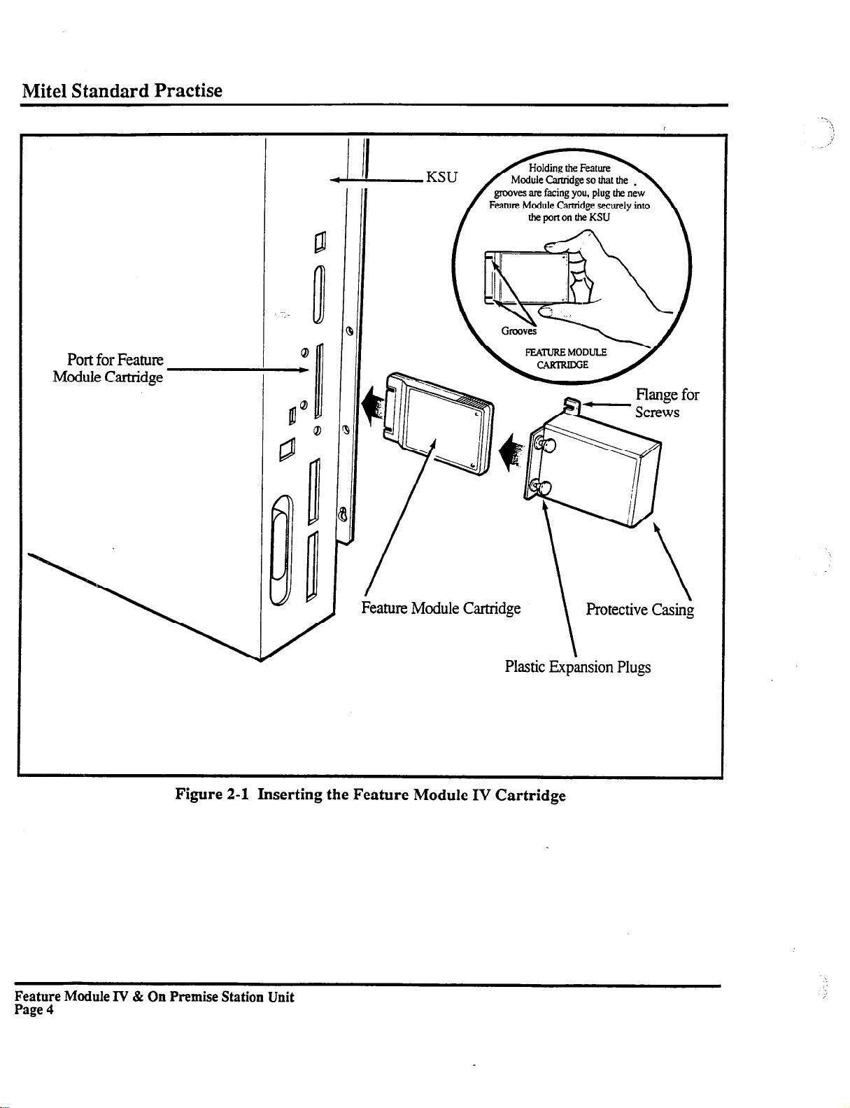
Inserting the Feature Module IV Cartridge
On Premise Station Unit
On Premise Unit Installation
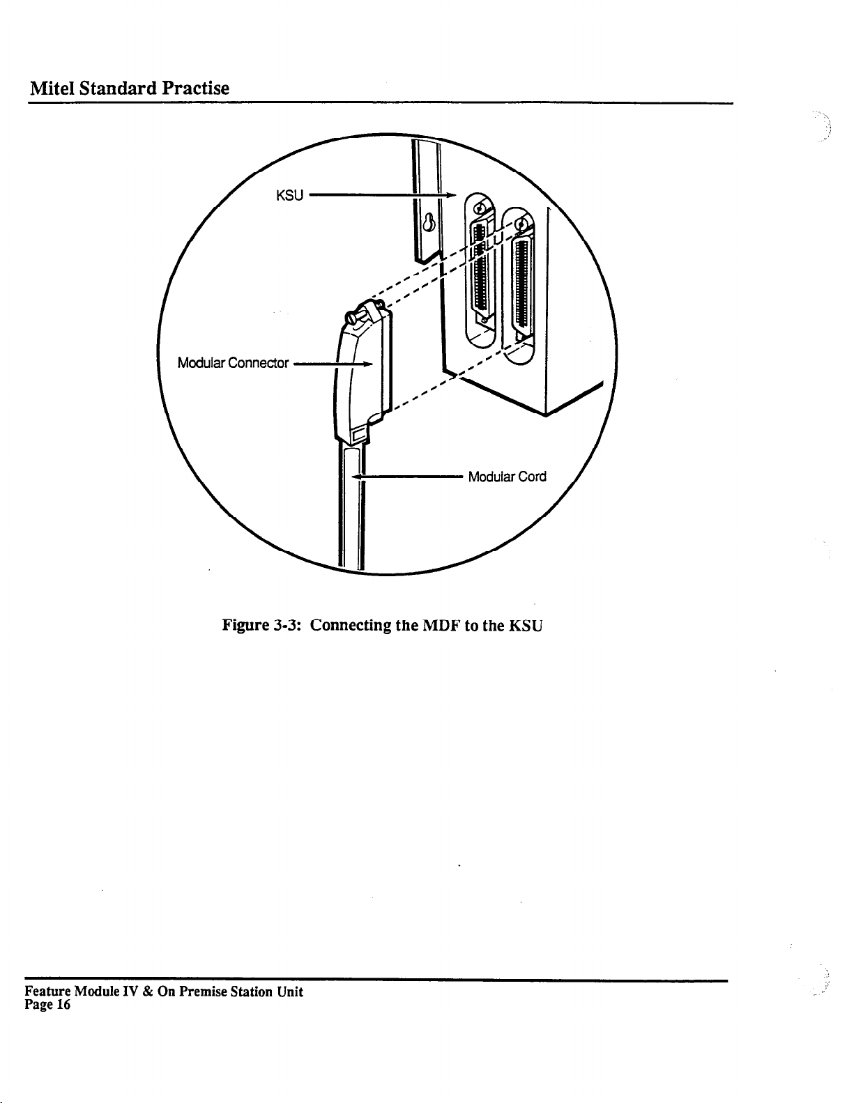
Connecting the MDF to the KSU
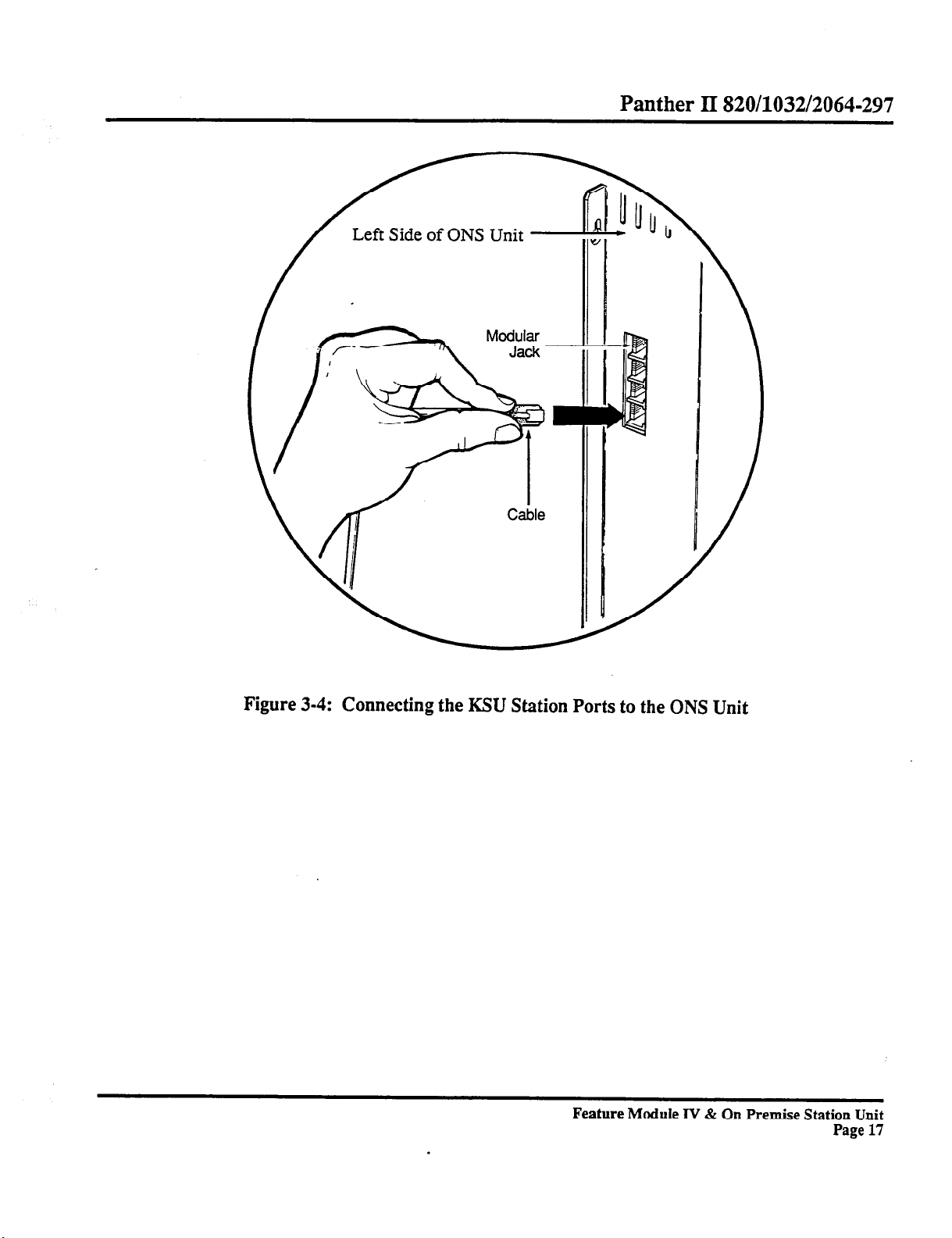
Connecting the KSU Station Ports to the ONS Unit
On Premise Station Unit Dipswitch
Setting Call Forwarding
Forwarding an External Call to Voice Mail
Forwarding an Internal Call to Voice Mail
........................................................
....................................................................................
............................................................................
.....................................................................
........................................
.................................................................
...................................................................................
.....................................................
.....................................................
PAGE
4
8
15
16
17
19
29
39
.41
0 Copyright 1990 of Mite1 Corporation. All Rights Reserved.
@ is a Registered Trademark of Mite1 Corporation.
Feature Module IV & On Premise Station Unit
Page iii
Page 6
1. INTRODUCTION
General
Panther II 820/1032/2064-297
1.01
1032/2064 Systems with Feature Module IV software and the On Premise Station Unit.
This Practice provides instructions for installing and programming Panther II 820/
Reason Far Issue
1.02 This is the first issue of this Practice. It is one of the set of Practices written to assist
a craftsperson install, operate and maintain the system in the field.
2. FEATURE MODULE IV SOFTWARE
General
2.01 In addition to providing the Panther II features outlined in the
Practice
820/1032/2064 Systems with the following:
of the
enhanced Call Forwarding,
improved extension displays,
displays for Transfer Ringing to the attendant, and
a change in the default setting of the Loud Bell Ringing/Ringing Over Paging feature
Panther II System Manual,
Feature Module IV software provides Panther II
Feature & Services
Feature Module IV software provides displays in English only.
Installation
2.02 The Feature Module IV Cartridge plugs into a port on Panther II 820 or 1032 Key
Service Units.
lined under the sub-heading
Cartridge in an existing installation follow the procedure given under the sub-heading
Replacing the Feature Module Cartridge.
CAUTION: Follow the
Cartridge correctly, you could damage the software on the Feature Module IV Cartridge,
or worse, damage the software in the Key Service Unit (KSU).
If you’re installing the system for the fmt time follow the procedure out-
Initial Installation;
instructions
carefully. If you don’t install the Feature Module IV
if you’re replacing the Feature Module
Feature Module IV & On Premise Station Unit
Page 1
Page 7
Mite1 Standard Practise
Initial Installation
(FOR PREVIOUSLY INSTALLED SYSTEMS, GO TO THE NEXT SECTION)
The
following instructions detail initial installation of the Feature Module IV Cartridge.
CAUTION: Don’t plug in the KSU power cord until you’re instructed to do so.
Step 1
Step
Step
Step 4
Step 5
Step
Step 7
Step
Mount the KSU as per the instructions in the INSTALLATION AND COMMISSIOZ-XNG PRACTICE of the PANTHER II SYSTEM
MANUAL.
There are two small grooves on the Feature Module IV Cartridge connector.
2
Holding the Feature Module IV Cartridge so that the grooves are facing you,
plug it securely into the port on the KSU (refer CO
ure 2-l).
push in the plastic expansion plugs, and tighten the two screws.
Install the remainder of the system as outlined in the INSTALLATION AND
3
COMMISSIONING PRACTICE OF THE PANTHER II SYSTEM MANUAL. After the system is completely installed, including the stations, plug in
the KSU power cord. Ensure the STATUS lamp on the side panel of the KSU
is flashing.
Set the MEM. CLEAR Switch to the ON position. The MEM. CLEAR Switch
(dipswitch #2) is located on the right-hand side panel of the KSU.
Press the RESET Switch.
6
Set the MEM. CLEAR Switch to the OFF position. The system is now reset to
the default settings.
Set the Battery Switch for the KSU memory to the ON position. The Battery
Switch (dipswitch #4) is located on the right-hand side panel of the KSU.
8
You must now program the system. Refer to the PROGRAMMING PRAC-
TICE in the PANTHER II SYSTEM MANUAL for instructions. You’ll find
programming instructions for the additional features provided by Feature
Module IV software and the On Premise Station Unit in this Practice.
Place the protective cover over the Feature Module IV Cartridge,
the close-up shown in Fig-
Feature Module IV & On Premise Station Unit
Page 2
Page 8
Panther II 820/1032/2064-297
Replacing the Feature Module Cartridge
The
following instructions detail the replacement of a Feature Module Cartridge in an ex-
isting installation.
Step 1
Step 2
Step 3
Step 4
Step 5
Step 6
Step 7
Step 8
Step 9
Step 10
Step 11
UNPLUG THE KSU POWER CORD. Telephone service will be disconnected.
Remove the Feature Module Cartridge protective cover. The protective cover,
located half-way down the right-hand side of the KSU, is secured by two
screws and two plastic expansion plugs. Loosen the two screws, pull back the
plastic expansion plugs and remove the protective cover.
Unplug the installed Feature Module Cartridge from the port on the side of the
KSU.
There are two small grooves on the Feature Module IV Cartridge connector.
Holding the replacement Feature Module IV Cartridge so that the grooves are
facing you, plug it securely into the port on the KSU (refer
to the close-up
shown in Figure 2-I).
Plug in the KSU power cord.
Replace the protective cover over the Feature Module IV Cartridge, push in
the plastic expansion plugs, and tighten the two screws.
Set the MEM. CLEAR Switch to the ON position. The MEM. CLEAR Switch
(dipswitch #2) is located on the right-hand side panel of the KSU.
Press the RESET Switch.
Set the MEM. CLEAR Switch to the OFF position. The system is now reset to
the default settings.
Ensure the BATTERY Switch for the KSU memory is in the ON position.
The Battery Switch (dipswitch #4) is located on the right-hand side panel of
the KSU.
You must now program the system with the customer’s feature selections.
Refer to the PROGRAMMING PRACTICE in the PANTHER II SYSTEM
MANUAL for instructions. Programming instructions for the additional
q
features provided by Feature Module IV software and the On Premise Station
Unit are given in this Practice.
Feature Module IV & On Premise Station Unit
Page 3
Page 9
Mite1 Standard Practise
rort ror reawe
Module Cartridge
I
~_ III I II
III I II
Feature
Module Cartridge
Plastic Expansion Plugs
Figure 2-1 Inserting the Feature Module IV Cartridge
Feature Module l”V & On Premise Station Unit
Page 4
Page 10
Additional Features
Panther II 820/1032/2064-297
2.03
This section provides descriptions and programming instructions for the additional
features that are available with Feature Module IV software.
Enhanced Call Forwarding
In addition to forwarding internal ringing calls and certain transfer ringing calls, Feature
Module IV software provides call forwarding of
l
Incoming external ringing calls, and
l
Internal DISA ringing calls
TO PROGRAM CALL FORWARDING AT A PANTHER SET
(See Note Below):
Step 1
Step 2
Dial *# to enter programming mode.
Dial one of the following 2-digit Call Forwarding codes:
21
for
Follow Me
(forwards internal ringing, transfer ringing, external ringing and internal DISA
Iinging calls)
22
for
Call Forward Busy
(forwards internal ringing, transfer ringing, external ringing and internal DISA
ringing calls)
23
for
Call Forward No Answer
(forwards internal ringing, external ringing and internal DISA ringing calls)
24
for
Call Forward Busy/No Answer
(forwards internal ringing, external ringing and internal DISA ringing calls)
Step 3
Dial the 2-digit number (10 to 73) of the station where you want the calls for-
warded to.
Step 4
Dial * to exit progratrnning mode.
Call Forwarding is now activated at the set.
TO TURN CALL FORWARDING OFF:
Step 1
Dial *# to enter programming mode.
Step 2 Dial 20
Step 3
NOTE: For instructions on programming an ONS port with Call Forwarding, refer to section
Dial * to exit programming mode. -
Feature Module IV & On Premise Station Unit
5.02.
Page 5
Page 11
Mite1 Standard Practise
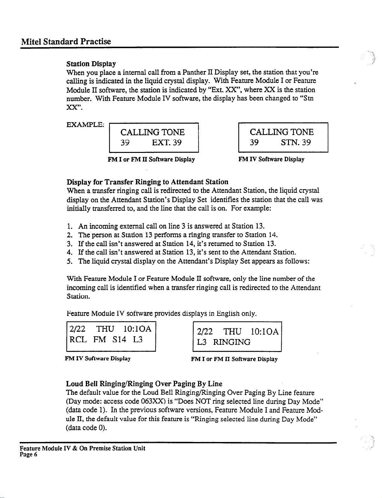
Station Display
When you place a internal call from a Panther II Display set, the station that you’re
calling is indicated in the liquid crystal display. With Feature Module I or Feature
Module II software, the station is indicated by “Ext. XX”, where XX is the station
number. With Feature Module IV software, the display has been changed to “Stn
xx”.
EXAMPLE:
FM
I or FM II Software Display
FM IV Software Display
Display for Transfer Ringing to Attendant Station
When a transfer ringing call is redirected to the Attendant Station, the liquid crystal
display on the Attendant Station’s Display Set identifies the station that the call was
initially transferred to, and the line that the call is on. For example:
1. An incoming external call on line 3 is answered at Station 13.
2. The person at Station 13 performs a ringing transfer to Station 14.
3. If the call isn’t answered at Station 14, it’s returned to Station 13.
4. If the call isn’t answered at Station 13, it’s sent to the Attendant Station.
5. The liquid crystal display on the Attendant’s Display Set appears as follows:
With Feature Module I or Feature Module II software, only the line number of the
incoming call is identified when a transfer ringing call is redirected to the Attendant
Station.
Feature Module IV software provides displays in English only.
VI pi
F’M
IV Software Display
Loud Bell Ringing/Ringing Over Paging By Line
The default value for the Loud Bell Ringing/Ringing Over Paging By Line feature
(Day mode: access code 063xX) is “Does NOT ring selected line during Day Mode”
(data code 1). In the previous software versions, Feature Module I and Feature Module II, the default value for this feature is “Ringing selected line during Day Mode”
(data code 0).
Feature Module IV & On Premise Station Unit
Page 6
FM I or FM II Software Display
,’
Page 12
3. ON PREMISE STATION UNIT
General
Panther II 820/1032/2064-297
3.01 The On Premise
Station (ONS) Unit provides a 4-port interface between Panther
II 820/1032/2064 Systems and the following devices:
l
single-line set
l
auto attendant
l
voice mail system
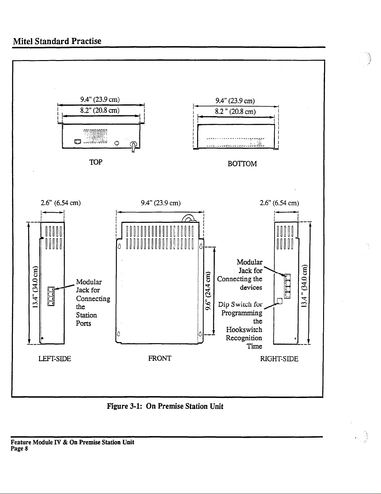
The ONS unit is a sealed unit of metal construction measuring 34.0 cm (13.4 inches) high,
23.9 cm (9.4 inches) wide and 6.54 cm (2.6 inches) deep.
Feature Module IV & On Premise Station Unit
Page 7
Page 13
Mite1 Standard Practise
2.6” (6.54 cm)
) Modular
Ports
9.4” (23.9
8.2” (20.8 cm)
TOP
Jack for
Connecting
the
Station
cm)
I
I
*I
9.4” (23.9
cm)
BOTTOM
2.6” (6.54 cm)
Modular
Jack for
Connecting the
devices
Dip Switch for
Programming
the
Hookswitch
Recognition
Time
LEFT-SIDE
Figure 3-1: On Premise Station Unit
Feature Module IV & On Premise Station Unit
Page 8
FRONT
RIGHT-SIDE
Page 14
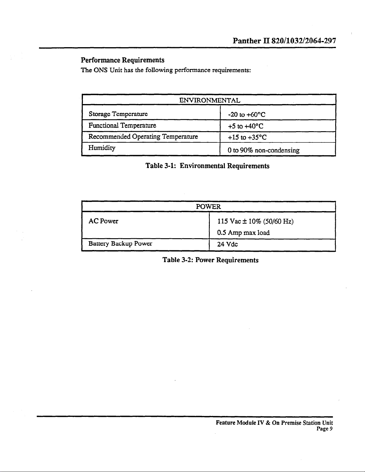
Performance Requirements
The ONS
Unit has the following performance requirements:
Panther II 820/1032/2064-297
ENVIRONMENTAL
Storage Temperature
Functional Temperature
Recommerided Operating Temperature
Humidity
Table 3-1: Environmental Requirements
AC
Power
Battery Backup Power
Table 3-2: Power Requirements
-20 to +6O”C
+5 to +40°c
+15 to +35”C
0 to 90% non-condensing
POWER
115 Vat k 10% (50/60 Hz)
0.5 Amu max load
1 24Vdc
Feature Module IV & On Premise Station Unit
Page 9
Page 15
1
Mite1 Standard Practise
#
A
B
C
D
Manual Access
Automatic Access
941
697
770
852
941
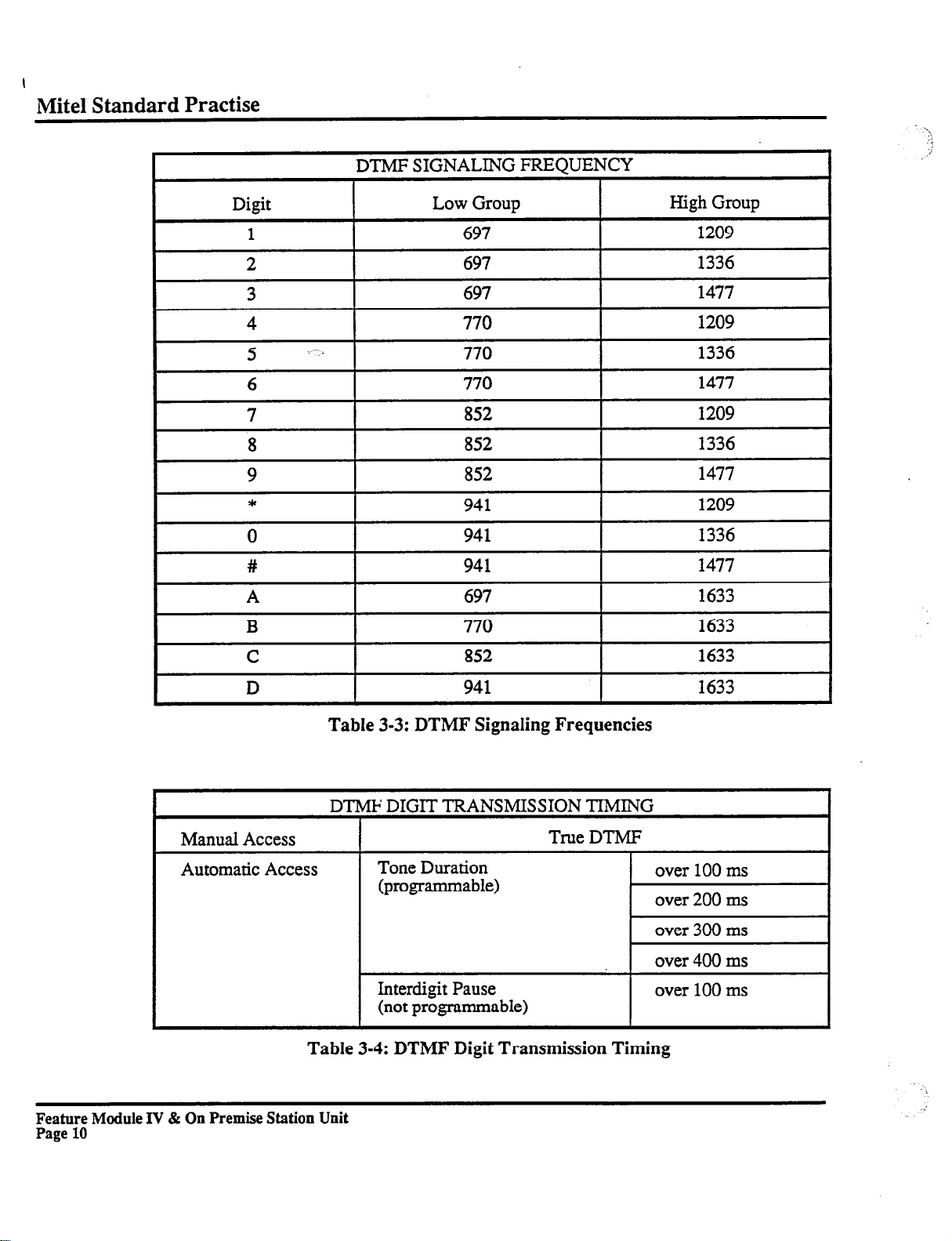
Table 3-3: DTMF Signaling Frequencies
DTMF DIGIT
Tone Duration
(programmable)
Interdigit Pause
(not programmable)
TRANSMISSION
True DTMF
TIMING
1477
1633
1633
1633
1633
over 100 ms
over 200 ms
over 300 ms
over 400 ms
over 100 ms
Table 3-4: DTMF Digit Transmission Timing
Feature Module IV & On Premise Station Unit
Page 10
Page 16
Panther II 820/1032/2064-297
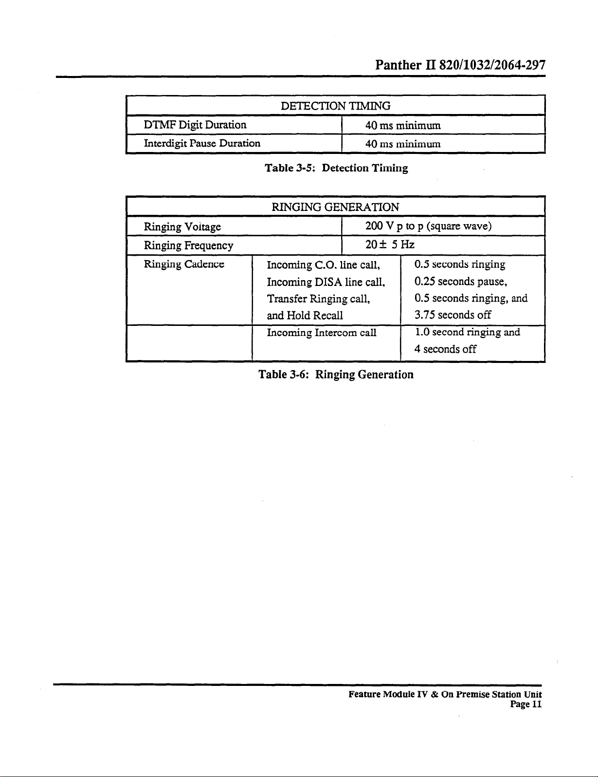
DETECTION TIMING
DTMF Digit Duration
Interdigit Pause Duration
Ringing Voitage
Ringing Frequency
40 ms minimum
I
I 40 ms minimum
Table 3-5: Detection Timing
RINGING GENERATION
200 V p to p (square wave)
209~
5Hz
Incoming C.O. line call,
Incoming DISA line call,
Transfer Ringing call,
and Hold Recall
Incoming Intercom call
Table 3-6: Ringing Generation
0.5 seconds ringing
0.25
seconds pause,
0.5 seconds ringing, and
3.75 seconds off
1.0 second ringing and
4 seconds off
Feature Module IV & On Premise Station Unit
Page 11
Page 17
Mite1 Standard Practise
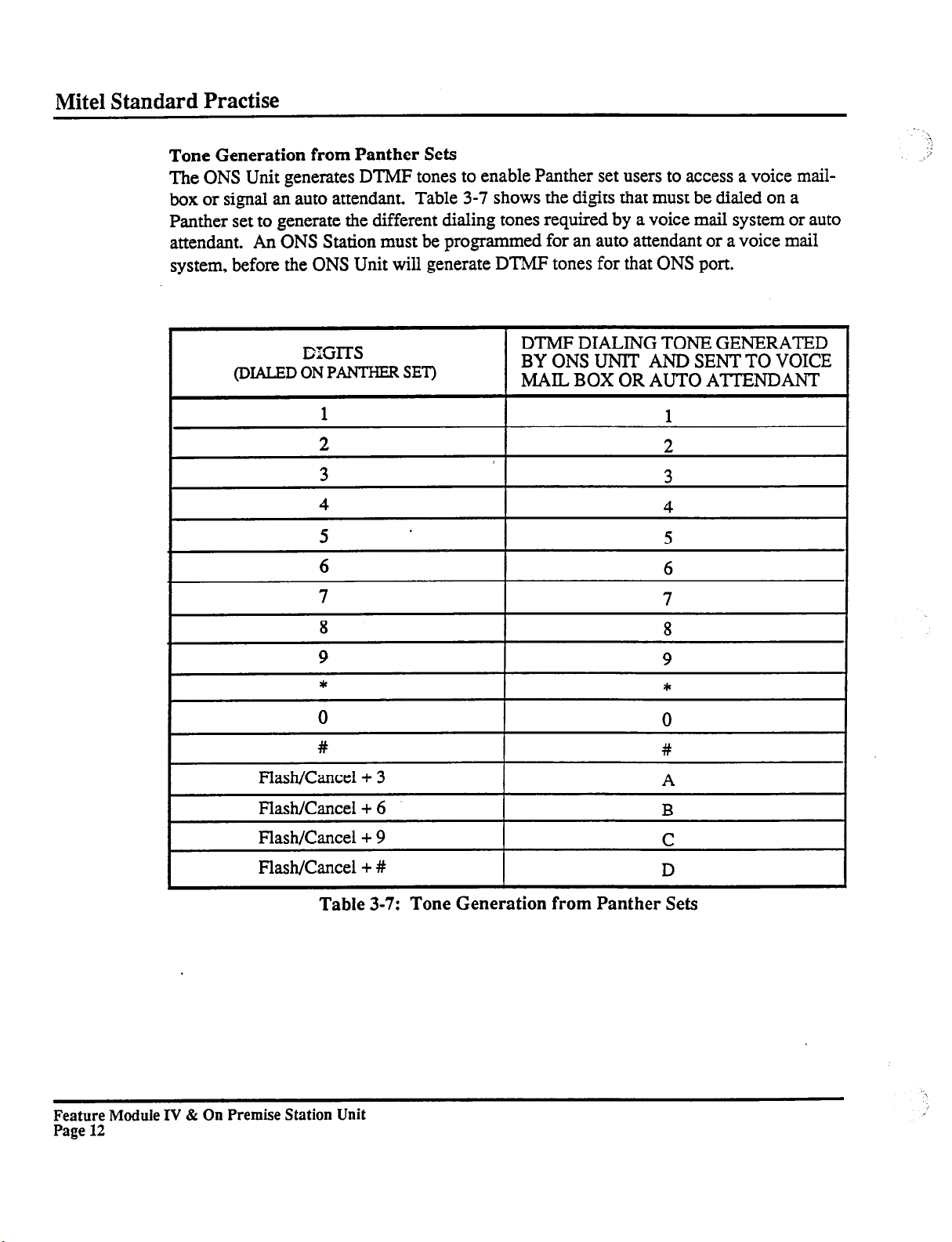
Tone Generation from Panther Sets
The ONS
box or signal an auto attendant. Table 3-7 shows the digits that must be dialed on a
Panther set to generate the different dialing tones required by a voice mail system or auto
attendant. An ONS Station must be programmed for an auto attendant or a voice mail
system, before the ONS Unit will generate DTMF tones for that ONS port.
Unit generates DTMF tones to enable Panther set users to access a voice mail-
-.
A
i
I
I
I
I-
lXGlTS
(DIALED ON PANTHEFt SET)
1
4
5
6
7
8
9
0
#
Flash/Cancel + 3
DTMF DIALING TONE GENERATED
BY ONS UNlT AND SENT TO VOICE
MAIL BOX OR AUTO ATTENDANT
1
1
t
4
5
6
8
9
*
0
#
A
I
I
I
I
I
Feature Module IV & On Premise Station Unit
Page 12
Flash/Cancel + 6
Flash/Cancel + 9
Flash/Cancel + #
Table 3-7: Tone Generation from Panther Sets
I
B
C
D
I
Page 18
Panther II 820/1032/2064-297
Direct Inward System Access
The ONS
tions Interface Unit and is programmed for Direct Inward System Access, then you can
call into the Panther II system and place internal calls directly to ONS stations.
Call Progress Tones
The ONS
The KSU provides the following call progress tones:
Unit is designed to operate with the DISA feature. If your system has an Op-
Unit provides the following call progress tones:
AUDIBLE RINGS:
- CO. line ringing tone
- btemal DISA ringing tone
- Transfer ringing tone
- Hold Recall ringing tone
- Intercom ringing tone
MANUAL TONE
BUSY TONE
BACK TONES
- Internal Calling (Tone Call)
- Internal Calling (Voice Call)
- All Page
- Zone Page
- Busy Override
EXECUTIVE OVERRIDE TONE
DIAL TONE
BUSY TONE
Feature Module IV & On Premise Station Unit
,
Page 13
Page 19
Mite1 Standard Practise
Installation
3.02 The
of Panther II 820,1032 and 2064 KSUs. The ONS Unit supports up to four devices and
each device occupies a station port on the KSU. In order for the ONS unit to operate,
Feature Module IV software must be installed in the KSU.
You can connect a maximum of two ONS Units to a Panther II 820,1032 or 2064 System. However, you can’t connect an ONS Unit to more than one KSU. For example,
you can’t connect two ONS ports to a Panther II 820/1032/2064 KSU and connect the
other two ONS ports to another Panther II 820/1032/2064 KSU.
You can install or remove the ONS Unit without disconnecting power to the system or
interrupting service to all stations.
plug in the ONS power cord. If the KSU isn’t powered up when you plug in the ONS
power cord, the ONS unit may not operate properly. In addition, if you disconnect any of
the modular cords that connect the KSU stations to the ONS Unit, you must disconnect
the power to the ONS Unit, After reconnecting the modular cords, you can then plug in
the ONS power cord (providing that the KSU is receiving power).
aren’t followed, the ONS Unit will not operate properly.
Follow the steps listed below to install the ONS Unit.
Step 1
Step 2
Step 3
Step 4
Step 5
Step 6
On Premise Station (ONS) Unit connects to station ports on the left-hand side
In fact, the KSU must be receiving power when you
If these procedures
Mount a main distribution frame (MDF) to the right of the KSU on the wooden
backboard. Then, mount the ONS Unit to the right of the MDF with the four
wood screws (refer to Figure 3-2).
Connect the MDF to the desired KSU station ports using a 25-pair cable and
two 50-pin ‘D’ Amp Connectors (refer to Figure 3-3).
Connect each of the four station ports from the MDF to one of the four modular
jacks on the left side of the ONS Unit. Use a DBU4 type cord (4-conductor
mod-to-mod cord) with an RJ14C connector to make the connection (refer to
Figure 3-4).
Each modular jack on the left-hand side of the ONS Unit corresponds to a jack
on the right-hand side. The modular jacks on the right-hand side connect to the
devices (single-line set, voice mail system or auto attendant). Connect the
modular jacks on the right-hand side of the ONS Unit to the devices using
DBU4 type cords with RJ14C connectors.
If the KSU power isn’t connected, plug in the KSU power cord.
Program the system to recognize the type of devices that are connected to the
ONS Unit. To program the type of device:
a. Connect a Panther II Display Set to Station 10
b. Dial *#015 to enter programming mode
Feature
Page 14
Module IV & On Premise Station Unit
Page 20

Panther II 820/1032/2064-297
c.
Dial access code 1OOYY where YY is the 2-digit station number of the
device
d.
Enter the desired data code:
5 for a single line set,
6 for a voice mail system, or
7 for an auto attendant
e.
Press the # key to store your selection
f.
Repeat steps c to e for each ONS station
g.
Press * to exit programming mode
ONS
KSU
ODULAR CONNECTOR
KRONE BLOCK
STANDARD SET
Figure 3-2: On Premise Unit Installation
Feature Module Iv & On Premise Station Unit
Page 15
Page 21
Mite1 Standard Practise
Modular Connector
c
Figure 3-3: Connecting the MDF to the KSU
Feature Module IV & On Premise Station Unit
Page 16
Page 22
Left Side of ONS Unit
Panther
II
820/1032/2064-297
Figure 3-4: Connecting the KSU Station Ports to the ONS Unit
Feature Module IV & On Premise Station Unit
Page 17
Page 23
Mite1 Standard Practise
Step 7
Step 8
Step 9
Program the type of line select for the ONS stations:
From the Panther II Display Set at Station 10
Dial *#015 to enter programming mode
Dial access code 113YY where YY is the 2-digit station number of the ONS
device
Enter the desired data code:
0 for Auto Intercom (for a voice mail system)
2 for Manual Line Select (single line set or auto attendant)
Press the # key to store your selection
Repeat steps c to e for each ONS station
Press * to exit programming mode
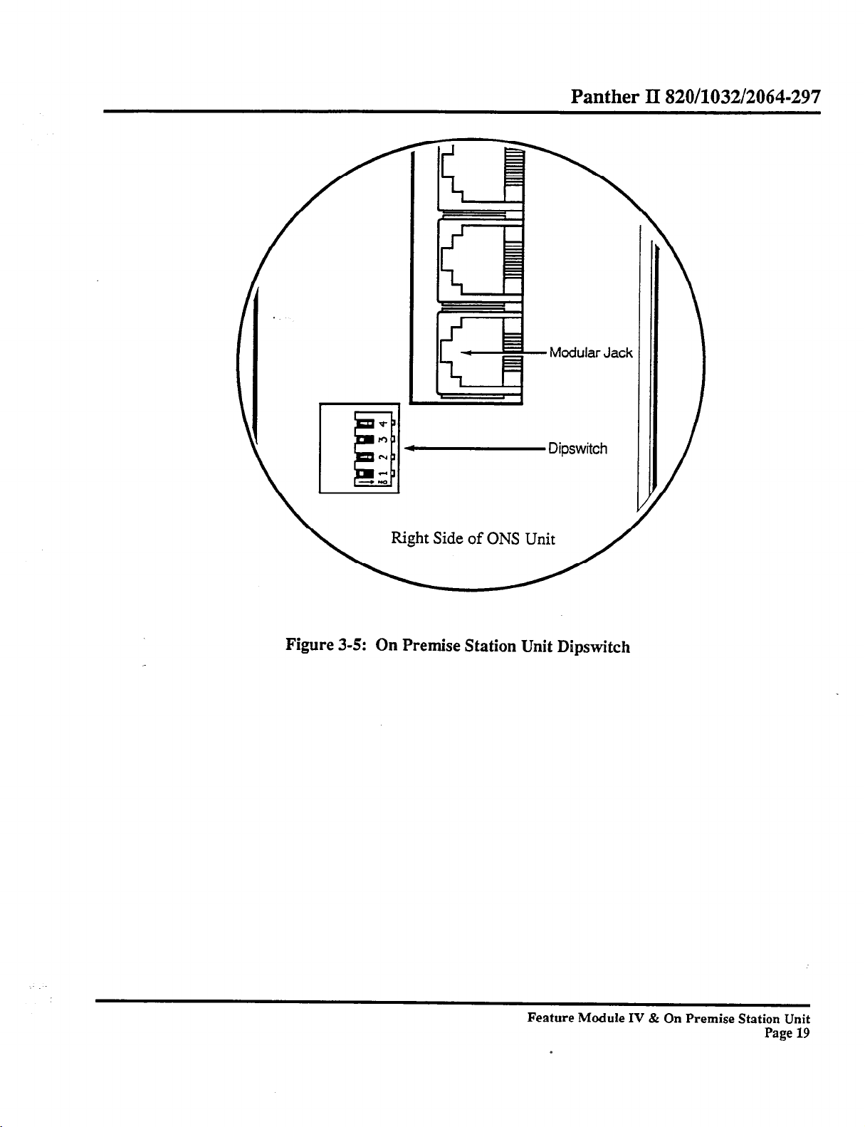
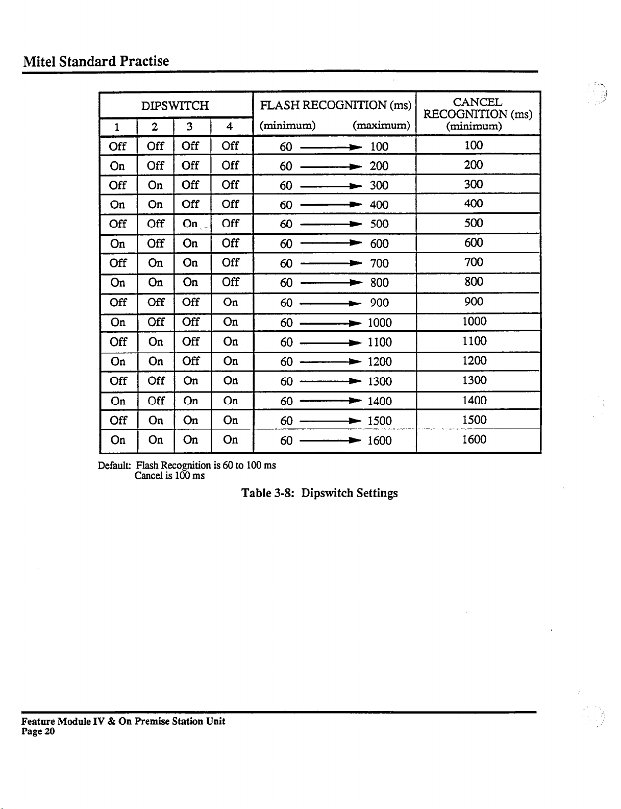
Adjust the dipswitches located on the right-hand side of the ONS Unit to set the
duration of the Flash/Cancel Recognition (refer to Figure 3-5 and Table 3-8).
The duration of the Flash/Cancel Recognition should be set to the duration of
the flash/cancel signal that is produced by the ONS devices. Note that the
dipswitch settings determine the Flash/Cancel Recognition for all four ONS
stations (i.e., you can’t set a different Flash/Cancel Recognition for each ONS
station).
Plug in the ONS power cord. The ONS device (e.g., standard tone telephone)
begins working approximately 6 seconds after you plug in the ONS power cord.
’
CAUTION: The KSU must be receiving power when you plug in the ONS power
cord. If you plug in the ONS power cord before plugging in the KSU power
cord, the ONS unit will not work properly.
Feature Module IV & On Premise Station Unit
Page 18
Page 24
Panther II 820/1032/2064-297
Dipswitch
Right Side of ONS Unit
Figure 3-5: On Premise Station Unit Dipswitch
Feature Module IV & On Premise Station Unit
Page 19
Page 25
Mite1 Standard Practise
On
Off
On
Off
On
Default: Flash Recognition is 60 to 100 ms
On
Off On On
Off On On
On On On
On On On
Cancel is 100 ms
Off On
Table 3-8: Dipswitch Settings
60 60 60 60 60 -
1200
1300
1400
1500
1600
1200
1300
1400
1500
1600
Feature Module IV & On Premise Station Unit
Page 20
Page 26
4. ON PREMISE STATION DEVICES
General
Panther II 820/1032/2064-297
4.01 This
special programming requirements.
section provides a brief description of each ONS device and identifies any
Single-Line Set
4.02 You can perform certain Panther features from a single-line
that’s connected to an ONS station. However, you must frst program the ONS station for
a single-line set (access code lOOYY, data code 5) and for Manual Line Select (access
code 113YY, data code 2) if you want to access both internal and external lines. Refer to
the ONS User Guide for instructions on using the set.
You can transfer calls from a Panther set to an ONS device. You can also transfer calls
from an ONS device to a Panther set. Before a call can be transferred from an ONS
device, you must program the flash-hook as a Transfer signal (access code 055, data
code 3).
(tone only)
telephone
Auto Attendant
4.03 An auto attendant answers and directs external calls to stations within the system.
Most auto attendants operate by prompting the caller to enter the number of the desired
station or to dial a specific digit for a particular department. When the caller enters the
desired station number or dials the desired digit, the auto attendant transfers the call. To
allow an auto attendant to transfer calls, you must program the flash-hook as a Transfer
signal (access code 055, data code 3) and set the Transfer Ringing Return feature to
“Return to Sub-Attendant” (access code 104YY, data code 1). If the Transfer Ringing
Return feature is left with the default setting, unanswered transfer calls return to the
originator. The default setting is inappropriate for an auto attendant because any unanswered transferred calls that were initially transferred by the auto attendant will be returned to the auto attendant.
You can program incoming external calls to ring at the auto attendant. To allow incoming
external calls to ring the auto attendant, you must program the lines to ring at the ONS
station port that the auto attendant port is connected to. Refer to
ment in the Programming Practice
When all the internal intercom paths are busy, the auto attendant is unable to transfer an
incoming external call.
of the
Panther II System Manual
Feature Module IV & On Premise Station Unit
Flexible Ringing Assign-
for instructions.
Page 21
Page 27
Mite1 Standard Practise
Incoming external calls can be transferred from a station to the auto attendant. The auto
attendant is able to answer and redirect the transferred call to a station.
transfer isn’t available with the Panther II System, an auto attendant can’t direct internal
calls to stations within the system. For the same reason, internal calls that are forwarded
to the auto attendant can’t be redirected either.
Calls that arrive at a busy ONS auto attendant port can be forwarded to another ONS auto
attendant port. Refer to the section
Voice Mail
Setting Call Forwarding in
Since internal call
this Practice.
4.04
corded messages. A person can call your mailbox and leave a recorded message for you.
Later, you can access your mailbox and listen to any messages that have been left for
you.
The ONS Unit can be programmed to allow callers to automatically access your voice
mailbox (see Section 5.03). If the ONS Unit is programmed to allow automatic access,
you can forward your calls directly to your voice mailbox by forwarding your set to the
ONS station that the voice mail system is connected to. If a caller, who has been forwarded from your set directly to your mailbox, leaves a recorded message, the ONS Unit
will send a message waiting signal to your set.
winks if you’ve a message waiting. To respond to a message waiting signal, press the #
key or Intercom key. If the message is entered in your mailbox you will access your
mailbox and hear the recorded message, but if the message was placed on your set from
another Panther set, you’ll simply ring that set.
If a message waiting signal is sent from a Panther set, single-line set or auto attendant to a
station that has call forwarding enabled, the message waiting signal will be forwarded to
the call forwarding destination. But, message waiting signals that are sent from a voice
mail system to a station that has call forwarding enabled will not be forwarded. So, if
someone leaves a recording in your voice mailbox while you have call forwarding enabled, your set will indicate that you’ve a message waiting. The message waiting signal
will not appear at the station that your calls are forwarded to. In order for the voice mail
system to send message waiting signals, the ONS station port that the voice mail system
is connected to, must be programmed for Auto Intercom Select (access code 113YY, data
code 0).
A voice mail system provides “voice mailboxes” in which callers can
The Intercom indicator lamp on your set
leave re-
Feature Module IV & On Premise Station Unit
Page 22
Page 28
Panther II 820/1032/2064-297
Calls that arrive at a busy ONS voice mail port can be forwarded to another ONS voice
mail port. Refer to the section
Setting Call Forwarding in
this Practice.
You can program incoming external calls to ring at the voice mail system
To allow
incoming external calls to ring a voice mail port, you must program the lines to ring at the
ONS station port that the voice mail system is connected to.
Assignment
in the
Programming Practice
of the
Panther II System Manual
Refer to
Flexible Ringing
for details.
Feature Module IV & On Premise Station Unit
Page 23
Page 29
Mite1 Standard Practise
5. ON PREMISE STATION UNIT PROGRAMMING
General Programming
5.01
ming parameters for the ONS Unit and ONS stations are listed in the tables of this chapter.
To program ONS features:
Step 1
Step 2
Step 3
Step 4
Step 5
Step 6
This chapter provides programming instructions for the ONS Unit. The program-
Dial *#015 on the Panther II Display Set at Station 10
Select the desired feature from the table and dial the appropriate 3- to 7-digit
access code.
To change the default, dial the data code of the desired setting.
Press the # key to store the data.
Repeat steps 2 to 4 for each system feature setting or each ONS station setting
that you wish to change.
Press the * key to exit programming. The new programming is complete
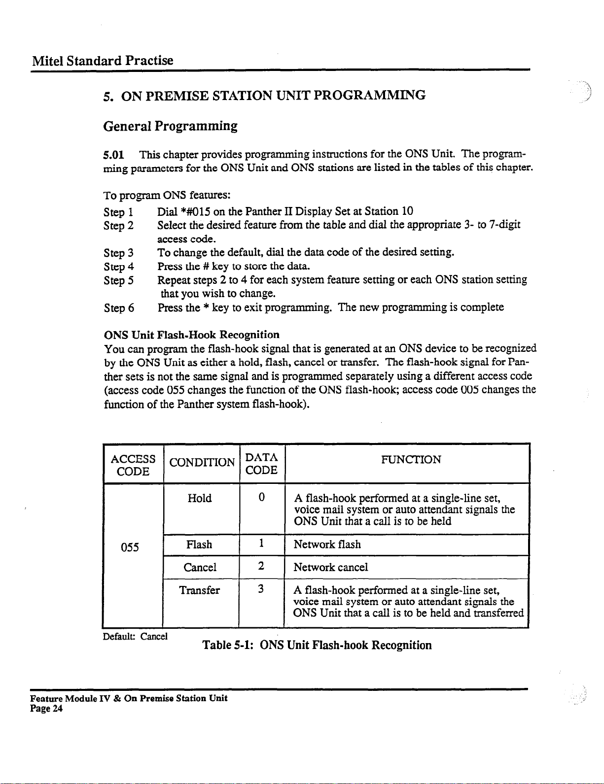
ONS Unit Flash-Hook Recognition
You can
by the ONS Unit as either a hold, flash, cancel or transfer. The flash-hook signal for Panther sets is not the same signal and is programmed separately using a different access code
(access code 055 changes the function of the ONS flash-hook, access code 005 changes the
function of the Panther system flash-hook).
program the flash-hook signal that is generated at an ONS device to be recognized
Hold
055
Default: Cancel
Flash
I
Cancel
r--
Transfer
Table 5-1: ONS Unit Flash-hook Recognition
Feature Module IV & On Premise Station Unit
Page 24
FVNCTION
0
1
I
2
I
3
A flash-hook performed at a single-line set,
voice mail system or auto attendant signals the
ONS Unit that a call is to be held
Network flash
I
Network cancel
I
A flash-hook performed at a single-line set,
voice mail system or auto attendant signals the
ONS Unit that a call is to be held and transferred
.’
Page 30
Panther II 820/1032/2064-297
The hold and transfer signals generated by the ONS unit are produced only within the
Panther system, whereas the flash and cancel signals are generated both within the Panther system and on the central office lines.
If you are connecting an auto attendant to an ONS port, or if you want to be able to transfer calls from a single-line set, you must program the flash-hook as a Transfer signal.
You can set the ONS Flash/Cancel Recognition time to correspond to the Flash/Cancel
signal produced by the ONS device by adjusting the dipswitch located on the right-hand
side of the ONS Unit (refer to Figure 3-5 and Table 3-8).
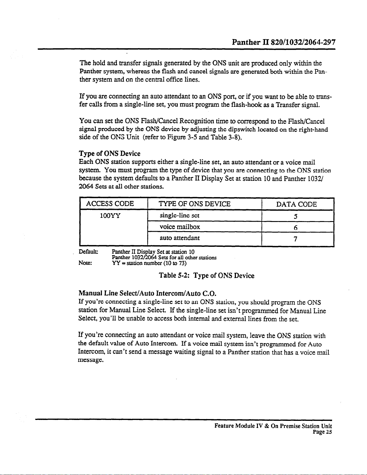
Type of ONS Device
Each ONS station supports either a single-line set, an auto attendant or a voice mail
system. You must program the type of device that you are connecting to the ONS station
because the system defaults to a Panther II Display Set at station 10 and Panther 1032/
2064 Sets at all other stations.
ACCESS CODE
1OOYY
Default: Panther II Display Set at station 10
Panther 1032/2064 Sets for all other stations
Note: YY = station number (10 to 73)
TYPE OF ONS DEVICE
single-line set
voice mailbox
auto attendant
DATA CODE
5
6
7
Table 5-2: Type of ONS Device
Manual Line Select/Auto Intercom/Auto C.O.
If
you’re connecting a single-line set to an ONS station, you should program the ONS
station for Manual Line Select. If the single-line set isn’t programmed for Manual Line
Select, you’ll be unable to access both internal and external lines from the set.
If you’re connecting an auto attendant or voice mail system, leave the ONS station with
the default value of Auto Intercom. If a voice mail system isn’t programmed for Auto
Intercom, it can’t send a message waiting signal to a Panther station that has a voice mail
message.
Feature Module IV & On Premise Station Unit
Page 25
Page 31

Mite1
Standard Practise
ACCESS CODE
1
LJNESELECT
1
DATA CODE
Default:
113YY
Auto
Intercom
Auto Intercom
Auto C.O.
Manual
I
Note:
Line Select
YY=station number
(10-73)
Table 5-3: Line Select
0
1
7
2
Table 5-4:
Feature Module IV & On Premise Station Unit
Page 26
ONS Station Features (continued on
page271
Page 32

Panther II 820/1032/2064-297
Tenant Groups
Zone Paging Groups
Prime Line Preference Groups
Intercom Tenanting/
Station Hunt Groups
Hunt Groups
Pickup Groups
Note 1:
Note 2:
Note
3:
Note 4:
Note 5:
An ONS station has Ringing
line set, auto attendant, or voice mail system.
These features must be programmed “0”
This feature isn’t available/applicable because
auto attendant, or voice mail system.
AA = the
copy to a block of other stations.
MM = the 2digit number of the first station in the block
NN = the 2-digit number of the last station in the block
YY = station number (10 to 73)
2-digit number of a station whose programming characteristics you would like to
ACCESS
CODE
I I
121YY No preprogrammed Tenant Groups
122YY
123YY
124YY
I I
1
125YY
Line Pickup, regardless of whether it is programmed for a single
No preprogrammed Zone Groups
No preprogrammed Prime Line
Preference Groups
All station in Group 1
1
All Stations in Group 1
there
DEFAULT
aren’t any DSS keys on a single line set,
Table
5-4:
Station Features
(continuedfrom page 26)
ONS
ONS Station Features
Table 5-4 lists the programmable station features that are applicable to an ONS single-line
Refer to the
settings available for each feature.
Programming Practice
of the
Panther I. System Manual
for the possible
Setting Call Forwarding
5.02
calls, internal ringing calls, internal DISA calls and certain transfer ringing calls to a
Panther station or another ONS station.
The ONS Unit has four station ports that you can connect to the ports of an auto attendant
or voice mail system. One possible application is to forward the calls that arrive at a busy
a voice mail or auto attendant port to another voice mail or auto attendant port. Note
however, that an ONS station is allowed only one call forwarding hop. For example, if a
call is forwarded from an ONS station port to another station that also has call forwarding
enabled, the call will not be forwarded a second time.
A single-line set, voice mail system or auto attendant can forward external ringing
Feature Module IV & On Premise Station Unit
Page 27
Page 33

Mite1 Standard Practise
To set Call Forwarding on or off, at an ONS single-line set,
Step 1
Step 2
Step 3
Step 4
Step 5
Lift the handset
Dial *#
Dial one of the following codes to specify the type of call forwarding:
2lfl for Follow Me (external, internal, internal
22YY for
23YY
Call Forward Busy (external, internal, internal DISA and transfer ring calls);
for Call Forward No Answer (external, internal, internal DISA calls);
24YY fo,Cusy/No Answer (external, internal,
20 to tum Call Forwarding off.
Note: YY = the number (10 to 73) of the station where you want your calls forwarded to.
DISA and
internal DISA calls); or
transfer ring calls);
Dial * to exit programming.
Hang up the handset
To set Call Forwarding on or off at an ONS station that is programmed for an auto attendant or voice mail system:
Step 1
Step 2
Step 3
Go to the Panther II Display set at station 10.
Dial *#015 to enter programming mode.
Dial access code 1OOYY (Type of Set) where YY is the ONS station number
of the voice mail system or auto attendant.
Step 4
Step 5
Step 6
Enter data code 0 for a Panther 1032/2064 Set.
Dial * to exit programming mode.
Unplug the modular cord (that corresponds to the auto attendant or voice mail
system) from the left-hand side of the ONS Unit (see Figure 5-l).
Step 7
Step 8
Step 9
Plug the RJ14 connector on the modular cord into a Panther II 1032/2064
Dial *#
Dial one of the following cqdes to specify the type of call forwarding:
Set
2lYY for Follow Me (external, internal, internal DISA and transfer ring calls);
22fl for Call Forward Busy (external, internal, internal DISA and transfer ring calls):
23YY for Call Forward No Answer (external, internal, internal DISA calls);
24YY for Busy/No Answer
20 to turn Call Forwarding off.
Note: YY = the number (10 to 73) of the station where you want your calls forwarded to.
Step 10
Step 11
Dial * to exit programming
Unplug the modular cord from the Panther 1032/2064 Set and plug it back into
the ONS station of the voice mail system or auto attendant.
Feature Module IV & On Premise Station Unit
Page 28
(external, internal, internal DISA calls); or
Page 34

Panther II 820/1032/2064-297
Step 12
Step
13
Step 14
Step
15
Step 16
Step 17
Return to the Panther II Display Set at station 10.
Dial *#IO15 to enter programming mode.
Dial access code 1OOYY (Type of Set) where YY is the ONS station
number of the voice mail system or auto attendant).
Enter 6 for a voice mail system, or 7 for an auto attendant.
Dial * to exit programming mode.
Unplug the power cord to the ONS unit. After waiting several
seconds reconnect the power to the ONS Unit.
Unplug the
modular cord
from the
ONS Station.
Plug it
into the
103242064
Set.
;$:j
$$
1032/2064 Set
%
Modular Cord
11111111111111
ONS
Programming Station 10
(Panther II Display Set)
Figure 5-1: Setting Call Forwarding
To Voice
Mail System
Unit
Feature Module
IV &
On Premise Station Unit
Page 29
Page 35

Mite1 Standard Practise
Programming Automatic
5.03
You can program the ONS Unit to allow Panther station users to forward their
Access.
to
a Voice Mail System
calls directly to their voice mailboxes. When the system has been programmed for automatic access people can redirect their incoming calls to their voice mailboxes simply by
call forwarding their sets to the ONS station number of the voice mail system
To enable automatic access, you must program DTMF digit strings into the ONS Unit
that will allow the voice mail system identify the type of calls and the stations’ voice
mailboxes. You program the DTMF digit strings and the voice mailbox numbers from
the Master Attendant Station. After programming the DTMF digits strings and voice
mailbox numbers, you have the option of setting conditions to automatic access.
In addition, you may have to change the default settings of some of the following parameters to allow the automatic access feature to work with your type of voice mail system:
l
DTMF Digit Timing
l
Pause Duration
l
Transfer Ringing Time
l
Tone/Pulse C.O. Lines
You program the parameters listed above from station 10.
Programming DTMF Digit Strings for Automatic Access
To program the type of calls:
Step 1
Step 2
Go to the Panther II Display Set at the Master Attendant Station.
Press the
Speed
key. The Intercom lamp winks slowly and the display is
blank.
Step 3
Enter the 3-digit code (from Table 5-5) that corresponds to the type of call.
The code will appear in the display as you enter it.
#80 the display will appear as follows:
Display Set LCD
For example, if you enter
Feature Module IV & On Premise Station Unit
Page 30
Page 36

Panther II 820/1032/2064-297
NO.
1
2
3
4
5
6
7
8
9
10
Note:
Step 4
TYPE OF CALL
External Incoming Forwarded Call
or
Internal DISA Forwarded Call
or
PP= Pause, Pause. The digit string for each type of call defaults to PP. You must change the
PP for each type of call to the digit string required by the voice mail system.
It’s also
possible to change the duration of the Pause signal using system programming.
(Refer to Table 5-9)
Table S-5: Programming Digit Strings for the Type of Call
Enter the DTMF string that is required by the voice mail system. The voice
mail system requires a specific DTMF string to recognize each type of call.
These DTMF strings should be provided in the documentation that is supplied
with the voice mail system. They can be a maximum of 5 digits in length.
The defaults are shown in Table
5-5.
You can program the following digits into the DTMF strings for the type of call:
0
to 9, *, #,
A,
B,
C,
D or Pause
However, for the Message Waiting data string (code #88), only A, B, C, or D can be
stored as the first digit. To enter an A, B, C, D tone or Pause, dial the digits/keys given
Table 5-6.
DTMFTONE
A
B
C
Flash/Cancel key +3
Flash/Cancel key+6
Flash/Cancel key+9
DIAL --
DTMF TONE
D
PAUSE
DIAL --
Flash/Cancel key +#
Conference key
Table 5-6: Dialing DTMF Tones
Feature Module IV & On Premise Station Unit
Page 31
Page 37

Mite1 Standard Practise
Example:
Display Set LCD
Step 5
Step 6
Item
voice mail system to the ONS Unit. A caller, forwarded from a station to the station’s
voice mailbox, can leave a message. If the caller leaves a message, the voice mail system
will send this signal (default A) and the mailbox number to the ONS Unit. The ONS unit
converts the mailbox number into the appropriate station number and sends a message
waiting signal to the Panther station. The Intercom indicator lamp on the Panther set will
flash to indicate that there is a message waiting. If the mailbox number doesn’t come-
spond to a station, the Panther KSU sends busy tone to the voice mail system. Remember, the ONS station port that the voice mail system is connected to, must be programmed
for Auto Intercom select, or a Message Waiting signal won’t be sent to the Panther set.
To confum the digit strings that you’ve stored:
Step 1 Press the
Step 2 Press the
Step
Repeat steps 2 to 4 for each type of call that you want the voice mail system to
recognize.
Press the
showing the date and time.
No. 9 in the Table 5-5, Message Waiting, is a DTMF digit string that’s sent from the
Station. The Intercom lamp turns on steady and the display is blank.
3
Enter the 3-digit code (from Table 5-5) that corresponds to the type of call
(e.g., #SO). The digit string stored for that code will be displayed.
Speaker
Display
Speed
key.
key. The Intercom lamp turns off. The display returns to
key on the Panther II Display Set at the Master Attendant
Example:
Display Set LCD
Step 4
Step 5
Feature Module IV & On Premise Station Unit
Page 32
Repeat steps 2 and 3 for each digit string that you wish to confirm.
Press the
showing the date and time.
Display
key. The Intercom lamp turns off. The display returns to
Page 38

Panther
Programming Voice Mailbox Numbers
Each Panther station that requires a voice mailbox, requires a mailbox number. The
mailbox number, which can be from one to three digits in length (i.e., 0 to 999), is programmed into the ONS Unit. The mailbox numbers are determined by the voice mail
system and you must refer to the manufacturer’s documentation to determine what they
can be. The voice mailbox numbers for the stations default to the Panther Station number
(e.g., Panther Station 12 is preprogrammed with the voice mailbox number 12).
To program voice mailbox numbers into the Panther system:
II
820/1032/2064-297
Step 1
Step 2
Step 3
Step 4
Step 5 Press the
Press the
Station. The Intercom indicator lamp begins winking.
Enter the WY where YY is the desired station number. The selected station
number is shown in the display. For example, if you dial #12 the display
appears as follows:
Display Set LCD
Enter the desired voice mailbox number (0 to 999). The display shows the
mailbox number as you enter it. For example, if you dial 02 the display will
appear as follows:
Display Set LCD
Repeat steps 1 to 3 for each station that you wish to program with a voice
mailbox.
returns to showing the date and time.
Speed
Speaker
key on the Panther II Display Set at the Master Attendant
key. The Intercom indicator lamp turns off. The display
Feature Module IV & On Premise Station Unit
Page 33
Page 39

Mite1 Standard Practise
To confii the mailbox numbers that you’ve stored:
Step 1
Step 2
Step
Step 4
Step 5
Reseting the Digit Strings and Voice Mailbox Numbers
You can
default settings. Note that the following procedure also clears all common speed dial
numbers and/or all private speed call numbers.
To reset the digit strings and/or the voice mailbox numbers:
Step 1
Step 2
Step 3
Press the
Station. The Intercom lamp turns on steady and the display is blank.
Press the
Enter the #YY where IT
3
for
Repeat steps 2 and 3 for each mailbox number that you wish to confirm.
Press the
showing the date and time.
reset the digit strings (for the type of call) and the voice mailbox numbers to the
Dial *##015 on the Panther II Display Set at Station 10
Dial 0701# to reset the data strings for the types of call. Note that all common
speed dial numbers will also be cleared.
and/or
Dial 0702# to reset the voice mailbox numbers. Note that all private speed
dial numbers will also be cleared.
Dial * to exit programming mode.
Display
Speed
that station will be displayed.
Display
key on the Panther II Display Set at the Master Attendant
key.
is the station number. The voice mailbox number
key. The Intercom lamp turns off. The display returns to
Setting Conditions to Automatic Access
You can
system. The system checks the validity of the data string for the type of call and the
validity of the origin of the call (station or line number). If the data meets the pro-
grammed conditions, access to the voice mail system will be allowed. If the data doesn’t
meet the programmed conditions, access will be denied. These conditions don’t apply to
the Message Waiting signal that’s sent from the voice mail system to the ONS Unit.
To program conditions to automatic access:
Step 1
Step 2
Step 3
Step 4
Step 5
Feature Module IV & On Premise Station Unit
Page 34
program the system to impose conditions on automatic access to the voice mail
Dial *#015 on the Panther II Display Set at Station 10
Dial access code 058.
Enter data code of the desired condition (Table 5-7)
Press the # key to store the data
Press the * key to exit programming
Page 40

Panther II 820/1032/2064-297
FEATURE
CODE
DATA STRING
Not Valid
ACCESS
Automatic
Access
058
Valid
Not Valid
Valid
Default:
Note: This table doesn’t apply to the Message Waiting signal that’s sent from the VM system to the ONS
Data code 1
Unit
CONDITION
STATION/LINE NUMBER CoDE
Not Valid
Not Valid
Valid
Valid
DATA
0
1
2
3
Table 5-7: Setting Conditions to Automatic Access
DTMF Digit Timing
When you dial
the voice mailbox from a Panther set, the DTMF tones generated by the
ONS Unit are true DTMF signals. However, for automatic access, you can adjust the
DTMF tone duration to the specific duration required by your voice mail system. Table
5-8 lists the possible tone durations that you can program for automatic access.
To
program
Step 1
Step 2
Step 3
Step 4
Step 5
the duration of the DTMF tones
Dial *##015 on the Panther II Display Set at Station 10
Dial access code 056
Enter data code of the desired setting (Table 5-8)
Press the # key to store the data
Press the * key to exit programming
FEATURE ACCESS CODE
DTMF Tone
Duration for
056
Automatic
Access
* =
Notes:
Interdigit pause time is approximately 100 ms (fixed value)
Default
DTMF TONE DURATION
Approximately 100 ms*
Approximately 200 ms
Approximately 300 ms
Approximately 400 ms
Table 5-S: DTMF Digit Timing
Feature
DATA CODE
0
1
2
3
Module IV & On Premise Station Unit
Page 35
Page 41

Mite1 Standard Practise
Pause Duration for Automatic Access
DTMF strings identify the type of call to the voice mail system (see Table 5-5) during
automatic access. As previously indicated, these DTMF strings can include Pause signals.
You can program the duration of the Pause signal to the specific duration required by your
voice mail system.
To program the Pause duration:
Step 1
Step
2
Step 3
Step 4
Step 5
Dial *Ml5 on the Panther II Display Set at Station 10
Dial access code 057
Enter data code of the desired setting (Table 5-9)
Press the # key to store the data
Press the * key to exit programming
FEATURE
Pause
Time
for
Automatic
Access
Default: Approximately 1 s
KCESS
CODE
057
CONDITIONS
Approximately 100 ms 0
Approximately 500 ms 1
Approximately 1 s 2
Approximately 2 s 3
Approximately 3s 4
DATA
CODE
I I
Table 5-9: Pause Duration for Automatic Access
Transfer Ringing Time
Transfer Ringing Time is the length of time a transferred call will ring at a set before the
call is redirected to the originator, a sub-attendant or the master attendant. If you are
programming your system for automatic access to a voice mail system, you must ensure
that the Transfer Ringing Time is not too short. The-Transfer Ringing Time must be
greater than the total time required for the voice mail system to answer the call and for the
ONS Unit to send the DTMF digit string to the voice mail system.
ing Time is too short, a call forwarded to the voice mail system will be redirected before it
is connected to a voice mailbox.
If the Transfer Ring-
Transfer Pinging Time > Tie required for VM system + Time required for ONS
Feature Module IV & On Premise Station Unit
Page 36
to answer a call Unit to Send DTMF
digit string to VM
system
Page 42

To program the Transfer Ringing Time
Panther II 820/1032/2064-297
Step 1
Step 2
Step 3
Dial *#015 on the Panther II Display Set at Station 10
Dial access code 017
Enter data code of the desired setting (Table’S- 10)
Step 4 Press the # key to store the data
Step 5
FEATURE
Press the * key to exit programming
ACCESS
CODE
Transfer
Ringing
017
Time
Defaulr
30 seconds
Table S-10: Transfer Ringing Time
CONDITIONS
10 seconds
20 seconds
30 seconds
45 seconds
1 minute
1.5 minute
Until call is Answered
l
DATA
CODE
0
1
2
3
4
5
6
Tone/Pulse C.O. Lines
This
programming parameter determines the type of dialing, tone or pulse, for each C.O.
line that is connected to the system. If the C.O. lines that are connected to your system
can receive either tone or pulse signals, program the system for tone type C.O. lines.
To program the system for tone type C.O. lines:
Step 1 Dial *Ml5 on the Panther II Display Set at Station 10
Step 2 Dial access code 060xX where XX is the line number
Step 3 Enter data code 0
Step 4
Press the # key to store the data
Step 5 Repeat Steps 2 to 4 for each C.O. line
Step 6
FEATURE
Tone/Pulse
Tw
Defauk Tone
Press the * key to exit programming
ACCESS CODE
060xX
CONDITIONS
Tone
Pulse
DATA CODE
0
1
TABLE 5-11: Tone/Pulse 60. Lines
Feature Module IV & On Premise
Station Unit
Page
37
Page 43

Mite1 Standard Practise
Examples of Call Forwarding to Voice Mail
External Incoming Call to Voice Mail by Call Forwarding
Figure 5-2 shows an example of an external incoming call being directed to a voice mail
box using the Call Forwarding feature. The steps listed below are shown in Figure 5-2.
Ian calls in on line 03 to Tony’s station.
1.
Tony’s station is programmed to ring for line 03, but Tony has programmed his set for
2.
Call Forward Follow Me to Station 20.
Ian’s call is forwarded to Station 20.
3.
Unit which is connected to a voice mail system. When the voice mail system answers,
the ONS Unit sends the following DTMF digits to the voice mail system:
Station 20 is connected to a port on the ONS
PPD 03 02
PPD = Type
03 = C.O.
02 =
Tony’s mailbox number
Ian is connected to Tony’s mailbox and leaves a recorded message.
4.
After Ian hangs up, the voice mail system sends the following DTMF string to the
5.
of call
line
number
ONS Unit:
A 02
A = Message Waiting data saing
02 =
Tony’s mailbox number
In response to this DTMF string, the ONS Unit sends a Message Waiting signal to
6.
Tony’s set. Tony’s Intercom lamp flashes.
When Tony responds to the Message Waiting signal by pressing the # key or
7.
Intercom
key, the ONS Unit sends the data string that’s programmed for Message
Waiting Answer to the voice mail system. The Message Waiting Answer data string
(P#3 in this example) signals the voice mail system to connect Tony with his voice
mailbox.
Feature Module IV & On Premise Station Unit
Page 38
Page 44

TONY
(Station 12)
Panther II 820/1032/2064-297
. . . . . . . . . . . . . . . . . .
PROGRAMMING
Assume the system has been programmed with the following:
Automatic Access is programed for the following: Data string=valid; Station/line=valid
Station 12 is programmed with Call Follow Me to ONS Station 20
Data string for Call Forward Follow Me of a C.O. call = PPD
The voice mailbox for station 12 is programmed as 02
The data suing for the Message Waiting is left as the default A
The data string for the Message Waiting Answer is P#3
_.
mgure 5-z: Forwarding an External Call to Voice Mail
_a _ _. - _ - __ -_ _ - _ _~
Feature Module IV & On Premise Station Unit
Page 39
Page 45

Mite1 Standard Practise
Internal Call to Voice Mail by Call Forwarding
Figure 5-3 shows an example of an internal call being directed to a voice mail box by Call
Forwarding. The following steps are illustrated in Figure 5-3:
Sue places an internal call to Lilianna.
1.
Lilianna is
2.
busy on her phone, but she has programmed her set for Call ForwardBusy
to Station 17, so Sue’s call is forwarded to Station 17.
Station 17 is connected to a port on the ONS Unit which is connected to a voice mail
3.
system.
When the voice mail system answers, the ONS Unit sends the following DTMF digits
4.
to the voice mail system:
A*D 16 155
A*D = Type of call
16 = Call Forwarding station
155 = Lilianna’s mailbox number
Sue is connected to Lilianna’s mailbox and leaves a recorded message. After Sue
5.
hangs up, the voice mail system sends the following DTMF string to the ONS Unit:
./
2
DC 155
LX =
Message Waiting data string
155 = Liliarma’s mailbox number
In
6.
response to this DTMF string, the ONS Unit sends a Message Waiting signal to
Lilianna’s set. Lilianna’s Intercom lamp flashes.
When Lilianna responds to the Message Waiting signal by pressing the # key or
7.
Intercom
key, the ONS Unit sends the data string that is programmed for Message
Waiting Answer to the voice mail system. The Message Waiting Answer data string
(C#B# in this example) signals the voice mail system’to connect Lilianna with her
voice mailbox.
Feature Module IV & On Premise Station Unit
Page 40
,’
Page 46

Panther II 820/1032/2064-297
Sue
(Station 11)
Liliana
(Station 16)
. . . . . . ..a..........
ONS
Unit
Voice Mail Unit
KSU
\
PROGRAMMING
Assume the system has been programmed with the following:
Aummatic Access is programed for the following: Data string=valid; Station/Xne=valid
Station 16 is programmed with Call Forward Busy to ONS Station 17
Data string for Call Forward Busy of an internal call = A*D
The voice mailbox for station 16 is programmed as 155
The data string for the Message Waiting is DC
The data string for the Message Waiting Answer is C#B#
Figure 5-3: Forwarding an Internal Call to Voice Mail
Feature Module IV & On Premise Station Unit
Page 41
Page 47

--
‘, _
.i” :
.’ i ‘.i i .,
‘. . .
.;,..:,
,‘- _
,_.
.,
,. _,
-,
: . . .
..:’
:,-: :. ,.
‘.
‘,
I.
INTERFACE HARDWARE
91-0556-1Az kc 1989 Printed in U.S.A.
TRILLIUM
hkphoner~stellm
F-3623-l
Page 48

Trillium Standard Practice Panther II 820/1032/2064-296
91 - 0566 - 1A Issue 1, October, 1989
Panther 0 II 820/1032/2064
Electronic Key TeIephone System
FEATURE MODULE II
& OPTIONS INTERFACE HARDWARE
TABLE OF CONTENTS
1.
INTRODUCTION
GENERAL
REASON FOR ISSUE
2. FEATURE MODULE IT SOFTWARE
GENERAL
INSTALLATION
Initial Installation
Replacing the Feature Module Cartridge
ADDITIONAL FEATURES
Additional Programmable Feature Keys
Transfer Ringing Return Displays
Remote Programming and System Status
3.
OPTIONS INTERFACE HARDWARE UNIT
GENERAL
INSTALLATION
FEATURES
Amplified Lines
Trunk to Trunk Conference
Direct Inward System Access
External Call Forward
PAGE
1
1
1
2
3
5
5
7
8
12
12
12
16
16
16
18
21
Feature Module II & Options Interface Hardware
Page i
Page 49

Trillium Standard Practice
0 Copyright 1989 of Mite1 Corporation. All rights reserved.
8 is a Registered Trademark of Mite1 Corporation.
I
Feature
Page ii
Module II & Options Interface Hardware
I
Page 50

1. INTRODUCTION
GENERAL
Panther II 820/1032/2064-296
1.01
This Practice provides instructions for installing and programming Panther II 820/
1032/2064 Systems with Feature Module II and Options Interface Hardware.
REASON FOR ISSUE
1.02 This is the first issue of this Practice. It is one of the set of Practices written to
assist a craftsperson install, operate and maintain the system in the field.
2. FEATURE MODULE II SOFTWARE
GENERAL
2.01 In addition to providing the Panther II features outlined in the
Practice
of the
Panther ZZ System Manual,
Feature Module II software provides
Panther II 820/1032/2064 Systems with the following:
l
additional Programmable Feature Keys,
l
enhanced displays for Transfer Ringing Return, and
l
Remote Programming and System Status (RPASS).
INSTALLATION
Feature & Services
2.02 The
Feature Module II Cartridge plugs into a port on Panther II 820 or 1032 Key
Service Units. If you’re installing the system for the fast time follow the procedure outlined under the sub-heading
Initial Installation;
if ycu’re replacing the Feature Module
Cartridge in an existing installation follow the procedure given under the sub-heading
Replacing the Feature Module Cartridge.
CAUTION: Follow the instructions carefully. If you don’t install the
Feature Module II Cartridge correctly, you could damage the software on the
Feature Module II Cartridge, or worse, damage the software in the Key Service
Unit (KSU).
Feature Module II & Options Interface Hardware
Page 1
Page 51

Trillium Standard Practice
Initial Installation
The following instructions detail initial installation of the Feature Module II
Cartridge.
CAUTION: Don’t plug in the KSU power cord until you are instructed to do so.
Step 1.
Step 2.
Step 3.
Step 4.
Step 5.
Step 6.
Step 7.
Mount the KSU as per the instructions in the
Practice
There are two small grooves on the Feature Module II Cartridge connector.
Holding the Feature Module II Cartridge so that the grooves are facing you,
plug it securely into the port on the KSU (refer to the close-up shown in Figure
2-l). Place the protective cover over the Feature Module II Cartridge, push in
the plastic expansion plugs, and tighten the two screws.
Install the remainder of the system as outlined in the
Commissioning Practice
completely installed, includin,
the STATUS lamp on the side panel of the KSU is flashing.
Set the MEM. CLEAR Switch to the ON position. The MEM. CLEAR Switch
(dipswitch #2) is located on the right-hand side panel of the KSU.
Press the RESET Switch.
Set the MEM. CLEAR Switch to the OFF position. The system is now reset to
the default settings.
Set the Battery Switch for the KSU memory to the ON position. The Battery
Switch (dipswitch #4) is located on the right-hand side panel of the KSU.
(for previously installed systems, go to the next section)
Installation and Commissioning
of the
Panther II System Manual.
of the
Panther II System Manual.
* the stations, plug in the KSU power cord. Ensure
Installation and
After the system is
Step 8.
Feature Module II & Options Interface Hardware
Page 2
You must now program the system. Refer to the
the
Panther II System Manual
instructions for the additional features provide by Feature Module II software in
this Practice.
for instructions.
Programming Practice
You’ll find programming
in
Page 52

Panther II 820/1032/2064-296
Replacing the Feature Module Cartridge
The following instructions detail the replacement of a Feature Module Cartridge in an
existing installation.
Step 1.
Step 2.
Step 3.
Step 4.
Step 5.
Step 6.
Step 7.
Step 8.
Step 9.
Step 10.
Step 11.
Set the MEM. CLEAR Switch to the ON position. The MEM. CLEAR Switch
(dipswitch #2) is located on the right-hand side panel of the KSU.
Press the RESET Switch.
Set the MEM. CLEAR Switch to the OFF position. The system is now reset to
the default settings.
Ensure the BATTERY Switch for the KSU memory is in the ON position. The
Battery Switch (dipswitch #4) is located on the right-hand side panel of the
KSU.
Unplug the KSU
power cord. Telephone service will be disconnected.
Remove the Feature Module Cartridge protective cover. The protective cover,
located half-way down the right-hand side of the KSU, is secured by two screws
and two plastic expansion plugs. Loosen the two screws, pull back the plastic
expansion plugs and remove the protective cover.
Unplug the installed Feature Module Cartridge from the port on the side of the
KSU.
There are two small grooves on the Feature Module II Cartridge connector.
Holding the replacement Feature Module II Cartridge so that the grooves are
facing you, plug it securely into the port on the KSU (refer to the close-up
shown in Figure 2- 1).
Plug in the KSU power cord.
Replace the protective cover over the Feature Module II Cartridge, push in the
plastic expansion plugs, and tighten the two screws. Replacement of the
Feature Module Cartridge is complete.
You must now program the system with the customer’s feature selections. Refer
to the
Programming Practice
in the
Panther II System Manual
for instructions.
Programming instructions for the additional features provided by Feature Module II software are given in this Practice.
Feature Module II & Options Interface Hardware
Page
3
Page 53

Trillium Standard Practice
FEATURE MODULE II CARTRIDGE
KSU
Port for Feature
Module II Cartridge
Feature Module II
Cartridge
Plastic Expansion Plugs
it securely into the pot-~ on the KSU.
Protective Casing
\
Flange for screws
Figure 2-I Installing the Feature Module II Cartridge
Feature Module II & Options Interface Hardware
Page 4
Page 54

Panther II 820/1032/2064-296
ADDITIONAL FEATURES
2.03 This section provides descriptions and programming instructions for the additional features that are available with Feature Module II software.
Additional Programmable Feature Keys
Panther II systems allow you to program feature codes into the line keys and Direct
Station Select (DSS) keys that are located on the set’s designation card (i.e., the line/DSS
keys that are located above the fixed function keys). Once you’ve programmed a line/
DSS key with a feature code, instead of accessing a line or station the key will provide
you with easy access to the feature.
You can program the following features into the programmable line/DSS keys of Panther
Sets that are connected to Panther II 820/1032/2064 Systems:
Feature
Saved Number Redial
Call Pickup - Local
Call Pickup - Remote
Night Pickup
Do Not Disturb
Program
Unused key
Code
050
057
058
059
060
061
062
Feature Module II software allows you to program an additional eight features into programmable line/DSS keys:
Feature
Service*
Background Music
All Call Page
ExternalPage
Executive Override
Answer All Call Page & Answer External Page
Relay Control OFF
Relay Control ON
* The
use Remote Programming and System Status, to program another system.
Service
key must be programmed for your Panther II Display Set before you can
Code
056
063
064
065
066
067
068
069
Feature Module II & Options Interface Hardware
Page 5
Page 55

Trillium Standard Practice
Programming
Feature keys are programmed at each individual set. To program a line/DSS key to
activate a feature:
Step 1.
Step
Step 3.
Step 4.
Dial *# (or press the
2.
Dial the digit 4.
Press the line/DSS key that you wish to program. Remember, you can only
program line/DSS keys that are located on the set’s designation card.
Dial the code of the desired feature (e.g., dial
activate background music).
Program
key) at the set.
063
to program the key to
.
J
.:.i
_:’
,
Step 5.
Press * to exit programming.
Note that you can return a key to its default setting by entering code 000 in Step 4.
Operation
Refer to the Panther II Feature Module II User Guide for details on how to use the programmable keys.
Operating Notes
The indicator Iamps beside keys that have been programmed as features won’t indicate
the status of the feature. For example, when the Relay Control ON key is pressed the
relay is activated, but the indicator lamp beside the Relay Control ON key doesn’t turn
on.
Before you can use a ReIay Control ON key or a Relay Control OFF key, the system
must be programmed for
Conrrof.
If the system is programmed so that the relay automatically returns to off
Relay Control
and for either
Automatic or Manual Relay
(default setting), then obviously you won’t require a Relay Control OFF key. Refer to
the
Programming Practice
in the
Panther II System Manual
for instructions on how to
program these parameters.
Relay Control ON/OFF keys only work at stations that have been programmed for
Relay Access.
The Master Attendant Station is the only station preprogrammed with
Relay Access.
Before you can use the Executive Override key at a set, the set must be programmed
with
Executive Override
capability.
A music source must be connected to the KSU before a Background Music key can be
used to activate background music.
Feature Module II & Options Interface Hardware
Page 6
‘.
Page 56

Panther II 820/1032/2064-296
Transfer Ringing Return Displays
Feature Module II software provides displays for the Transfer Ringing Return feature.
When an incoming external call is transferred to another station, if the call isn’t answered
within a programmable time period the call will either:
l
return to the station that transferred the call, then be sent to the Master Attendant
Station (or sub-attendant, if sub-attendants are programmed),
l
be sent directly to the Master Attendant Station (or sub-attendant, if sub-attendants are
programmed), or
l
not be returned (i.e., ring at the station that the call was transferred to, until the call is
answered >.
For the first transferred call that is returned, the liquid crystal display on a Panther II
Display Set will identify the station that the call is being returned from, and the line that
the call is on.
Programming
The callback destinations are programmed individually for each station using Transfer
Ringing Return. The length of time that the call will ring at an unanswered set before
being returned is programmed using Transfer Ringing Time. Refer to the Programming
Practice in the Panther II System Manual for instructions on how to program these para-
meters. The default settings for these parameters are as follows:
Transfer Ringing Return - returns call to the station that initially transferred the call,
then sends the call to the Master Attendant Station.
Transfer Ringing Time -
30 seconds.
Operation
If a transferred call is returned to a Panther II Display set, the liquid crystal display will
show:
l
the number of the station that the call is being returned from, and
l
the line number of the call.
Example:
Feature Module II & Options Interface Hardware
Page 7
Page 57

Trillium Standard Practice
If a name has been programmed for the station that the call is being recalled from, the
name instead of the station number will appear in the liquid crystal display.
Example:
Operating Notes
Assume your station is programmed to have unanswered, transferred calls returned to
your set, then returned to the Master Attendant Station. If you transfer two incoming
external calls to different stations and neither of the transferred calls are answered, the
fast call will be returned to your set and the second will be camped on. However, if the
second call is returned while the first call is ringing at your set, the second call will be
rerouted to the Master Attendant Station.
Recalled from Tony
Line 3
Remote Programming and System Status
The Remote Programming and System Status (RPASS) feature allows Panther II 820/
1032/2064 Systems to be programmed from a remote location. Basically, it’s designed to
allow a dealer, using a Panther II Display Set, to program a customer’s Panther II system
from his/her office.
Using the RPASS feature doesn’t require any additional hardware at either the dealer’s
premises or the customer’s premises. However, both the dealer and the customer must
have a Panther II system with Feature Module II software. Although the dealer must have
a Panther II Display set, the customer doesn’t require one.
Preparation
Before you can use RPASS, you must install a Panther II Display set at your Station 10
and program it with a
Feature Keys
for instructions on how to program a
You also require the 4-digit RPASS access code of the Panther II system that you wish to
program. This 4-digit access code must be programmed into the customer’s system at the
customer’s premises prior to using RPASS. There is no preprogrammed value for this
code.
To program a customer’s Panther II system with a 4-digit RPASS access code:
Step 1.
At the customer’s premises go to Station 10.
Step 2. Dial *# (or press the
Service key
Program
(refer to the previous section
Service
key).
key) on the set.
Addirional Programmable
Feature
Page 8
Module II & Options Interface Hardware
Page 58

Panther II 820/1032/2064-296
Step 3. Dial 015. The Intercom indicator lamp turns on and the display confirms that
you are in programming mpde.
Step 4. Dial 028. The Intercom indicator lamp flashes quickly.
Step 5. Enter the desired 4-digit
Step
6.
Dial # to store the code. The Intercom indicator lamp comes on steady.
Step 7. Dial * to exit programming mode.
RPASS
access code.
Using
RPASS to Program a Customer’s System
Once a 4-digit RPASS access code has been programmed, you can use RPASS to program the customer’s system from a Panther II Display Set in your office. To program a
customer’s system using RPASS:
Step 1. Call the customer from the Panther II Display Set at your Station 10. Ensure the
line that you are using is programmed for tone dialing (see the section, Tone or
Pulse
in the
Step
Programming Practice
2.
When your call is answered, ask the person who answers if you’re connected
of the
Panther II System Manual).
with the Master Station (default Station 10). If you aren’t, request that your call
be transferred to the Master Station.
Step 3. When you’re connected with the customer’s Master Station, instruct the person
you’re speaking with to:
. press the
Conference
key, and
’ dial#Ol.
The indicator lamp of line that you’re using for RPASS will flash
very
slowly.
While you’re programming the system, the person at the Master Station can use
his/her set; however, the line being used for RPASS programming will be busy.
In addition programming can’t be accessed from the customer’s premises until
you release the RPASS connection.
Step 4. Dial #, press the
Service
key, enter the 4digit RPASS access code and dial #
again. The type and software version of the system you are programming will
be displayed in the set’s liquid crystal display. You are now in programming
mode.
Feature Module II & Options Interface Hardware
Page 9
Page 59

Trillium Standard Practice
Step 5. Dial the 3-
(The feature access codes are given in the Programming Prucrice). Each digit
will be displayed in your set’s liquid crystal display as you dial it. The setting
currently programmed for the feature will be displayed.
to
7-digit access code of the feature you wish to change, then dial #.
_..
--1
_ /
:,
Access code 000 for
Current setting for Hold Recall Time
Data Code = 2 so Hold Recall Time is
Programmed for 1 minute.
Hold Recall Time
Step 6. To change the current setting, dial the access code again, dial the data code of
the desired feature setting, then press the # key (data codes and possible feature
settings are also given in the
Programming Pracrice).
Your selection will
appear in the display.
To
change current feature setting, enter
the access code again followed
code of the desired setting: then dial #.
New setting appears in the display.
by the data
If you enter an ineligible access or data code “--P” will be displayed. If you
make an error simply re-enter the access and data codes correctly, then dial #.
Step
7.
Repeat Steps 5 and 6 for each additional feature you wish to change.
Feature Module II & Options Interface Hardware
Page 10
Page 60

Panther II 820/1032/2064-296
Step 8. To confirm your programming selections enter the first access code by dialing
OOO##. Press # to step through each access code.. The data code currently pro-
grammed for each access code will be displayed.
Press # to step to the next feature.
The access code and data code
programmed for the system are
displayed.
Step 9. Press the * key to exit programming and release the line. Programming is com-
plete.
Step 10. Hang up’the handset or, if handsfree, press the
Operating Notes
l
If you hang up while using RPASS, the system will automatically release the line.
The system will also release the line if you don’t press any keys for 3 minutes.
l
You can’t use the
Flash/Cancel
key to delete an inputting error or use the
to increment the access code during RPASS programming.
l
The customer won’t be able to enter programming mode from their Station 10 while
you’re using RPASS to program their system. Conversely, if the customer is in pro-
gramming mode at their Master Attendant Station, you won’t be able to enter programming mode on their system using RPASS.
Speaker
key.
Hold
key
Feature Module II & Options Interface Hardware
Page 11
Page 61

Trillium Standard Practice
3. OPTIONS INTERFACE HARDWARE UNIT
GENERAL
3.01
When used with Feature Module II software, the Options Interface Hardware
Unit enhances the operation of Panther II systems by providing the following
new features:
l
Amplified Lines,
l
Trunk to Trunk Conference,
l
External Call Forward, and
l
Direct Inward System Access.
Note that you can only use the Options Interface Hardware Unit if your system has
Feature Module II software. In addition the Options Interface Hardware Unit uses the
following stations on the Key System Unit (KSU):
l
Stations 28 to 29 on the Panther II 820 System
l
Stations 28 to 33 on the Panther II 1032 System
l
Stations 28 to 33 on the Panther II 2064 System
Therefore, sets connected to these stations will be inoperative.
INSTALLATION
3.02 The Options Interface Hardware Unit connects to a port on Panther 820 or 1032
Key Service Units. Follow the procedure listed below to install the Options Interface
Hardware Unit.
Step 1.
Step 2.
Step 3.
Step 4.
Step 5.
Ensure the Battery Switch for the KSU memory is in the ON position. The
Battery Switch (dipswitch #4) is located on the right-hand side panel of the
KSU.
Unplug the KSU power cord. Telephone service ,will be disconnected.
Remove the woodscrew from the bottom right-hand flange of the KSU.
Position the Options Interface Hardware Unit connection plate over the screw
hole in the bottom right-hand flange of the KSU (refer to Figure 3-l). Then,
replace the screw you removed in Step 3.
Mount the Options Interface Hardware Unit to the right of the KSU on the
wooden backboard. Align the screw hole in the bottom left-hand comer of the
Options Interface Hardware Unit with the screw hole in the connection plate
(as shown in Figure 3-4). Fasten the Options Interface Hardware Unit to the
wooden backboard with the four wood screws.
Step 6.
There’s a short strip of black tape along the lower right-hand side of the KSU
that covers two ports. Starting at the top of the tape, peel it back to expose the
top port (refer to Figure 3-2). Cut off the excess tape.
Feature Module II & Options Interface Hardware
Page 12
Page 62

275”
5% Crr
Panther II 820/1032/2064-296
1.5”
(3.76 cm)
1 = 7.7" (19.6
14.75” (37.46 cm)
cm) 4
Figure 3-l Mounting the Options Interface Hardware Unit
Step
7.
Plug one end of the supplied ribbon cable into the port that you uncovered in
Step 6. Refer to Figure 3-3 to locate the correct port on the KSU. The connector fits into the port only one way. Don’t attempt to force the connector into the
port.
Step 8. Plug the other end of the ribbon cable into the port on the left panel of the
Options Interface Hardware Unit.
Step 9
Plug in the KSU power cord.
Feature Module II & Options Interface Hardware
Page 13
Page 63

Trillium Standard Practice
1
0
Key
Service
\
Unit
3
0
2
0
Figure 3-2 Exposing the Port for the Ribbon Cable
Feature ModLIe II & Options Interface Hardware
Page 14
Page 64

Panther II 820/1032/2064-296
Figure 3-3 Connecting the Ribbon Cable
Key Service Unit
Figure 3-4 Installation Complete
Feature Module II & Options Interface Hardware
Page 15
Page 65

Trillium Standard Practice
FEATURES
3.03 This section provides descriptions and programming instructions for the features
made available by the Options Interface Hardware Unit.
Amplified Lines
Normally, during an external conference there is a slight reduction in the voice signals
over the C.O. lines. To remedy this inconvenience, the Options Interface Hardware Unit
has a built-in amplifier that compensates for reductions in the voice signals on external
conference calls.
External conference calls can be set up with either amplified lines or non-amplified lines.
If you initiate a external conference call and you hear two bursts of tone, the lines you are
using are amplified. If you hear a single burst of tone, then the external conference has
been established with non-amplified lines.
The Options Interface Hardware Unit can amplify any four C.O. lines at one time. Trunk
to Trunk Conference, External Call Forwarding and external calls using Direct Inward
System Access each require two amplified lines. If you set up an external conference
when all the amplified lines are busy, you will hear a single tone. The single tone indicates that you aren’t using amplified lines and that you can’t set up a Trunk to Trunk
Conference. If you try to use External Call Forwarding or Direct System Inward Access
when all the amplified lines are busy, you will hear continuous ringing.
Trunk to Trunk Conference
The
Options Interface Hardware Unit allows you to set up trunk to trunk conferences
using amplified lines. When you’re on an external conference call, you can hang up
while allowing the two external parties to remain connected for a preprogrammed length
of time. Before the preprogrammed time period expires, the outside parties will hear an
1 l-second tone. Either party can restart the preprogrammed time period by dialing *
during the tone. If neither person dials
second tone.
Programming
The
length of time that the external parties remain connected after you hang up is programmable. The possible selections are: 0 minutes, 3 minutes (default setting), 5 minutes and 10 minutes. To change the default setting:
Step 1. At Station 10, dial *# (or press the
Step
2.
Dial 015. The Intercom indicator lamp turns on and the display confms that
you’re in programming mode.
Step 3.
Dial 024 (access code for Trunk to Trunk Conference). The Intercom indicator
lamp flashes quickly.
*, they will be disconnected at the end of the ll-
Program
key).
Feature Module II & Options Interface Hardware
Page 16
Page 66

Panther II 820/1032/2064-296
Step 4.
Dial the data code of your selection:
Length of Time
0 m@es (No
: IIIXIIE; (default semng)
10 minutes
Trunk ‘9 Trunk Conferencing)
Data Code
0
;
3
Step 5. Dial # to store your selection. The Intercom indicator lamp comes on steady.
Step 6 Dial * to exit programming mode.
Operation
You must establish an external conference call on amplified lines before you can set up
a Trunk to Trunk Conference:
While on an external call,
l
Press the
The call will be placed on hold and the line indicator lamp
l
Press +e
l
Dial the desired telephone number
Hold
key
key of an external line
will
flash
quickly.
Afrer the called party answers,
l
Press the
l
Press the line key of the call on hold
Conference
key
If you hear two short bursts of tone, you have set up the conference on amplified
lines. You must be using amplified lines to set up a Trunk to Trunk Conference. If
you hear a single burst of tone, you aren’t using amplified lines and won’t be able to
set up a Trunk to Trunk Conference.
During the conference call, you can hang-up and the two external
parties
wiI1 remain connected for a preprogrammed length of time (providing the conference was
set up using amplified lines and the system is programmed for Trunk to Trunk Con-
ferencing). Before hanging up, tell the external parties that they can expect to hear
an II-second warning tone before being disconnected. Explain to them that if they
wish to continue their conversation either of them can restart the timer by dialing *
during
the tone. If neither party dials
*, the call will be disconnected at the end of
the II -second tone. Note that the party that dials the * must have a tone dial set.
Before either party hangs up, one of them must dial O# to release the lines.
party dials O# before hanging up, the system will automatically release the lines
when the preprogrammed time for Trunk to Trunk Conferences has expired.
You can
re-enter a Trunk to Trunk Conference anytime before the preprogrammed time
period expires. To re-enter a Trunk to Trunk Conference:
Feature Module II & Options Interface Hardware
If neither
Page 17
Page 67

Trillium Standard Practice
With the handset in the cradle,
l
Dial *,
press the line key of one of external lines being used for the
conference
or
Dial *0, dial the line number (01-20) of one of the external lines being
used for the conference
Two tones announce your entry into the call in progress.
l
Lift the handset.
Operating Notes
If you exit and then re’enter a Trunk to Trunk Conference, the timer for the Trunk to
Trunk Conference will be restarted when you hang up.
Direct Inward System Access (DISA)
The Direct Inward System Access (DISA) feature allows you to call into the Panther II
system from a telephone located outside the office and--
* place calls using Panther II system C.O. lines, or
l
make internal calls directly to Panther stations.
You are most likely to use DISA to make work-related, long-distance calls from your
home phone, from a local telephone in a client’s office, or from a pay phone, during or
after normal working hours. The advantage of using DISA is that you’re making your
long-distance call on one of the Panther system C.O. lines, so the call will be billed to
your office and not to the telephone that you’re calling from.
You can also use DISA to place an internal call directly to a station in the office. This
saves you from having to go through the Master Attendant to call a station.
Two amplified lines are required to place an external call using DISA, but amplified lines
aren’t required to place a DISA call to a station in the office. So, you can be using DISA
to call a station and there will still be four amplified lines available for Trunk to Trunk
Conferences, External Call Forwarding or for making external calls using DISA. However, if all four of the system’s amplified lines are being used when you try to access the
system on the DISA line, you will hear continuous ringing and must try again later.
Programming
Any two C.O. lines may be programmed as incoming DISA lines. The only exception to
this rule is that you can’t program an incoming ECF line as a DISA line.
Once you’ve accessed the system using DISA, you can call any station, or use any C.O.
line to make an external outgoing call. However, before you can access the system, you
must enter a 4-digit DISA access code. Since there is no default value for this code, you
must program at least one DISA access code. Up to four DISA access codes can be programmed for the system.
Feature Module II & Options Interface Hardware
Page 18
Page 68

Panther II 820/1032/2064-296
You can program each of the incoming DISA lines separately for Day or Night Mode
operation. Each of the lines can have one of four possible settings:
l
Day off/Night off - DISA won’t work during the Day or Night Mode (default setting),
l
Day on/Night off - DISA will work only during Day Mode,
l
Day off/Night on
l
Day on/Night on - DISA will work during both Day and Night Mode.
You can also change the default setting of the release time for the DISA feature. The
release time determines the length of time allowed for an external call made using the
DISA feature. Note that the length of time you select also determines the release time
for the ECF feature.
In summary, the parameters that you must program for DISA are:
incoming lines for DISA,
the DISA access codes,
Day/Night Mode for incoming line 1,
Day/Night Mode for incoming line 2 (if programmed), and
the DISA/ECF release time.
Follow the procedure listed below to program the system for DISA:
Step 1.
Step 2.
Step 3.
At Station 10, dial *# (or press the
Dial 015.
Program the incoming DISA lines:
a.
Dial access code 0300=Xx where XX=the number of the line desired for incoming DISA
line 1.
b. Dial # to store the line number.
If
a second incoming DISA line is desired,
c. ~~~~es.s
- DISA will work only during Night Mode, or
Program
code 0301=Xx where XX=the number of the line desired for incoming DISA
key).
Step 4.
Step 5.
d. Dial #’ to store the line number.
Default: No lines programmed for DISA.
Note: Later, you may want to disable DISA. To disable DISA line 1 enter access code 0300=00
in step a. To disable DISA line 2, enter access code 0301=00 in step c.
Program the desired
a. Dial 029OXXXX#
b. Dial 0291XXXX# where XXXX=the desired 4-digit code for the
c. Dial 0292XXXX# where XXXX=the desired I-digit code for the third DISA access code.
d. Dial 0293XXXX# where XXXX=the desired 4-digit code for the fourth DISA access code.
Default: No codes.
Program
a. Dial access code 0380.
b. Dial data code 0 for Day off/Night off (default setting),
the Day/Night Mode selection for incoming DISA line 1.
DISA access codes:
where XXXX=the desired 4-digit code for the fit
1 for Day on/Night off,
2 for Day off/Night on, or
DISA access code.
second DISA access code.
3 for Day on/Night on.
c. Dial # to store your selection.
Feature Module II & Options Interface Hardware
Page 19
Page 69

Trillium Standard Practice
Step 6.
Program the Day/Night Mode selection for incoming DISA line 2 (only if you
programmed an incoming DISA line 2 in Step 3).
a. Dial access code 0381.
Step 7.
b. Dial data code 0 for Day off/Night off (default setting),
c. Dial # to store your selection.
Enter the desired release time. Note that the length of time selected will also
1 for Day on/Night off,
2 for Day off/Night on, or
3 for Day on/Night on,
determine the release time for ECF. To program the DIWECF release time:
a. Dial access code 027.
Step 8.
b. Dial data code 0 for 30 seconds,
Dial # to store the release time.
C.
Press * to exit programming.
1 for 1 minute (default setting),
2 for 2 minutes,
3 for 3 minutes,
4 for 5 minutes, or
5 for 10 minutes
Operation
You can only use the DISA feature from a tone dial (DTMF) telephone.
To make an internal call to a station:
Call into the office on an incoming CO. line that is programmed for DISA
You
will hear two bursts of ringing and then the system automatically provides internal
dial tone.
Dial #XXXX# (where XXXX=the 4-digit DISA access code)
If you enter the code correctly you’ll hear internal dial to&e;
you will hear an error tone.
If you hear error tone, you must hang up and call again.
if
you
enter it incorrectly,
Dial # then dial the number (10-73) of the desired station
You
will hear internal ringing tone. If your call isn’t answered you may dial *, dial #
then dial the number of another station, or dial * and hang up. If your call is an-
swered, when
you finish
your conversation, simply
Hang up to end the call
To access a C.O. line and place an outgoing call:
l
Call
into the offke on an incoming C.O. line that is programmed for DISA
You
will hear two bursts of ringing and then the system automatically provides internal
dial tone.
l
Dial #XXXX# (where XXXX=the 4-digit DISA access code)
If you enter the code correctly you’ll hear internal dial tone; if
you will hear an error tone.
l
Dial 3, then dial the number (01-20) of the desired line
You
will hear internal dial tone. If you hear a busy signal dial *, dial 3 then dial the
number of another line.
If you hear error tone, you must hang up and call again.
When you have internal dial tone,
you
enter it incorrectly,
Feature Module II & Options Interface Hardware
Page 20
Page 70

Panther II 820/1032/2064-296
Dial the desired telephone number
l
After several seconds of silence you will hear ringing.
begin your conversation. If the parry doesn’t answer dial O# and hang up the handset.
Both you and the person you’re speaking with will hear an I1 -second warning tone
before the preprogrammed release time expires. If you wish to continue your conversation, either you or the person you’re calling can dial * during the tone to restart the
timer. Note that the person that dials the * must have a tone dial (DTMF) set.
Dial 0## and hang up to end the call
l
When the person answers,
Operating
No
tez
Since the Options Interface Hardware Unit can’t create HALTS or PAUSES, the DISA
feature can’t be used behind Private Branch Exchanges (PBXs) that require HALTS or
PAUSES in dialing sequences.
Trunk to Trunk Conferences, External Call Forwarding and external calls using Direct
Inward System Access each use two amplified lines. The Options Interface Hardware
Unit only has the capability of providing four amplified lines at any given time.
four amplified lines are being used when you call in on the DISA line, you will hear
continuous ringing. You must hang up and try again. When amplified lines become
available, you will be able to use the DISA feature.
DISA callers aren’t subject to the class of service (toll restriction) applied to the line
that they are calling out on.
When DISA is enabled for a line, calls can’t come directly in on that line. A person
who attempts to call in on a line enabled for DISA will be dropped after approximately 20 seconds unless he/she enters the DISA access code.
If an SMDR Unit is connected to the system, the DISA access code used to make an
external DISA call is printed in the 77 to 80 column of the SMDR printout.
Don’t use DISA lines to make outgoing calls from the office because this will tie up
the DISA lines. If a person tries to call in on a busy DISA line, he/she will hear busy
tone.
It’s possible, although not advisable, to program an outgoing ECF line as an incoming
DISA line, However, the system will respond with the error message, “--P”, if you try
to program an incoming ECF line as a DISA line.
If all
External Call Forward
The External Call Forward (ECF) feature allows incoming external calls to be automatically forwarded to the telephone of another external number. For example, when working at home, you can have the incoming external calls that come into the office on a
specific line forwarded to your home phone.
You can program two lines to handle incaaing external calls for external call forwarding.
Each incoming line is assigned to an outgoing line that will forward incoming external
calls to an external number. The attendant programs the external numbers for the outgoing lines in common speed dial codes 98 and 99.
Feature Module II & Options Interface Hardware
Page 21
Page 71

?killium Standard Practice
Programming
There are four parameters that you must program for external call forwarding:
l
incoming lines for external call forwarding,
l
the outgoing lines for external call forwarding,
l
the release time, and
l
the external numbers that you want the calls forwarded to.
To program the system for external call forwarding:
At
Step 1.
Step
2.
Step
3.
step
4.
Step 5.
Step
6.
Station JO, dial *# (or press the
Dial 015.
Program
a.
Dial access code 0310=Xx where XX=the number of the desired line.
b. Dial # to store the line number.
,If you programmed a second outgoing ECF line, you must program a second incoming
ECF line,
Dial access code 031 I=XX where XX=the number of the desired line.
z:
Dial # to store the
Note:
To
ing ECF line 2, enter access code 03 1 l=OO in step c.
Program the outgoing ECF lines that you want assigned to the incoming ECF
lines:
a.
Dial access code 0410=Xx where XX=the number of the desired line for outgoing ECF
line 1.
b. Dial # to store the line number.
If a second outgoing ECF line is desired,
c.
Dial access code 04 1 l=XX where XX=the number of the desired line for outgoing ECF
line 2.
d. Dial # to store the line number.
Note: To disable outgoing ECF line 1 enter access code 04 lO=OO in step a. To disable outgoing
ECF line 2, enter access code 04 1 l=OO
Enter the desired DISA/ECF release time. The release time deter-t-nines the
length of time allowed for an ECF call. Note that the length of time selected
will also determine the release time for the Direct Inward System Access feature. To change the default setting of the release time:
Dial access code 027.
i:
Dial data code 0 for 30 seconds
c. Dial # to store the release time.
Press * to exit programming.
-.
the incoming ECF lines:
line number.
disable incoming
ECF line 1 enter access code 03 IO=00 in step a.
1 for 1 minute (default setting),
2 for 2 minutes,
3 for 3 minutes,
4 for 5 minutes, or
5 for 10 minutes.
Program
in step c.
key).
To
disable incom-
Feature Module II & Options Interface Hardware
Page 22
Page 72

Panther II 820/1032/2064-296
Step 7. Program the telephone numbers that you want the calls forwarded to, at the
Master Attendant Station.
Press
the Speed key.
i:
Dial speed call code 98.
Dial the
C.
line 1 (programmed in Step4).
d. Press the Speaker key.
If you’ve programmed a second pair of lines for
e. Press the
F. Dial speed call code 99.
g. Dial the telephone number to be stored. This number will be assigned to outgoing ECF line
2 (programmed
h. Press the Speaker key.
Note:
Operation
Briefly, this is how External Call Forwarding works (refer to Figure 3-5):
ECF is enabled by dialing *08 1 at the Master Attendant Station.
A caller dials the telephone number of a line that has been programmed as an ECF
i:
incoming line.
When the external incoming call rings the line, the call is automatically diverted onto
3.
the corresponding outgoing ECF line.
The system dials the preprogrammed telephone number (stored in either common
4.
speed call code 98 or 99) for that outgoing ECF line.
When the person at the telephone of the preprogrammed telephone number answers,
5.
he/she is connected with the caller.
Both parties will hear an 1 l-second warning tone before the preprogrammed release
6.
time expires. If they wish to continue their conversation, either party can dial * on
their set during the tone to restart the timer. Note that the party that dials the * must
have a tone dial (DTMF) set.
7.
When the call is completed either party must dial O# to release the line.
ties forget to dial O# before hanging up, the system will automatically release the line
after a preprogrammed length of time (default value 1 minute).
8.
ECF can be disabled by dialing *080 at the Master Attendant Station when it’s no
longer required.
telephone number to be stored.
Speed
key.
in Step4).
A HALT or PAUSE shouldn’t be programmed into a number for an outgoing ECF line
because the Options Interface Hardware Unit can’t create HALTS or PAUSES in dialing
sequences.
This
number
ECF,
will be
assigned to outgoing
ECF
If both par-
Feature Module II & Options Interface Hardware
Page 23
Page 73

Trillium Standard Practice
ECF Incoming
Caller dials telephone
number of incoming
line 1.
Panther II System
Feature Module II
System dials speed
call stored in common
speed call coda 98.
System dials speed
call stored in common
speed call code 99.
Outgoing ECF
Line 1
Call rings telephone
set at the stored number,
Caller dials telephone
number of ECF incoming
Line 2.
Operating
l
External call forwarding is enabled at the Master Attendant Station by dialing “08
and disabled by dialing *080.
l
Trunk to Trunk Conferences, External Call Forwarding and external calls using Direct
Inward System Access each use two amplified lines. The Options Interface Hardware
Unit only has the capability of providing four amplified lines at any given time.
Therefore, if all four amplified lines are being used, when you call in on the incoming
ECF line, you will hear continuous ringing. You must hang up and try again.
l
Since the Options Interface Hardware Unit can’t create HALTS or PAUSES, the ECF
feature can’t be used behind Private Branch Exchanges (PBXs) that require HALTS or
PAUSES in dialing sequences.
l
Don’t use ECF lines to make outgoing calls from the office because this will tie up the
ECF lines. A person calling in to a busy ECF line will hear busy tone. If the outgoing
ECF line is busy, the person calling in on the corresponding incoming ECF line will
hear continuous ringing.
Call rings telephone
set at the stored number.
Figure 3-5 External Call Forwarding
Notes
1
Feature Module II & Options Interface Hardware
Page 24
Page 74

9%0471-1BZ Dee
1989 Printed in
U.S.A.
F-3609-1
Page 75

Trillium Standard Practice
91-0471-1B
Panther II 820/1032/2064
Electronic Key Telephone System
GENERAL INFORMATION
Panther II 820/1032/2064-100
Issue 2, June 1989
TABLE OF CONTENTS
1.
2.
3.
4.
GENERAL
Introduction
Reason
SYSTEM OVERVIEW
General
Key Service Unit
Panther Telephone Sets
Direct Station Selection/Busy Lamp Field @SS/BLF) Console
Ancillary Devices
FEATURES OVERVIEW
SYSTEM REQUIREMENTS
Figures
System Configuration
Key Service Unit
Panther 1032 Set
3ZStation DSS/BLF Console
&I-Station DSS/BLF Console
For Issue
PAGE
1
1
7
8
10
11
11
12
7’
8
10
10
Tables
Panther Telephone Set Migration
Panther II 820 System Configuration Maximums
Panther II 1032 System Configuration Maximums
Panther II 2064 System Configuration Maximums
Environmental Requirements
Power Requirements
MF Signaling Frequency
Pulse Rate and Make Ratio
DTMF Dialing Speed
3
4
2
12
12
13
13
13
General Information
Page i
Page 76

Trillium Standard Practice
;
General Information
Page ii
6 Copyright 1989 of Mite1 Corporation. All Rights Reserved.
03 is a Registered Trademark of Mite1 Corporation.
. .
Page 77

1. GENERAL
Introduction
Panther II 820/1032/2064-100
1.0 1
2064 Electronic Key Telephone Systems. It outlines the major functional
This Practice provides a general description of the Panther II 820,
1032 and
elements,
features and the electrical characteristics of each system
Reason For Issue
1.0
2 This is the second issue of this Practice. It is one of the set of Practices written
to assist a craftsperson install, operate and maintain the system in the field. The
remaining Practices in the set are:
Features and Services
Programming
Installation and Commissioning
Maintenance and Troubleshooting
Door Answer Unit
Power Fail Transfer Unit
Station Message Detail Recording
Off-Premises Extension Unit
FAX Interface Unit
6-Line Expander Unit
2.
SYSTEM OVERVIEW
Panther II 820/1032/2064-105
Panther II 820/1032/2064-205
Panther II 820/1032/2064-200
Panther II 820/1032/2064-320
Panther II 820/1032/2064-290
Panther II 820/1032/2064-29 1
Panther II 820/1032/2064-292
Panther II 820/1032/2064-293
Panther II 820/1032/2064-294
Panther lI 820/1032/2064-295
,
the
91-0472
91-0473
9 l-0474
91-0475
9 l-0500
91-0501
9 l-0502
9 l-0542
91-0513
91-0514
General
2.0
1 The
Panther II 820 system is comprised of one Panther II 820 Key Service Unit
(KSU). The Panther II 1032 system is comprised of one Panther II 1032 KSU, while
the Panther II 2064 system consists of two KSUs: a Panther II 1032 KSU and a
Panther II 2064 KSU. Each system can be enhanced by the addition of a number of
optional ancillary devices. See Figure 2-l. The Panther II systems are designed for
easy migration, meaning that systems can be easily expanded to accommodate more
lines/stations, while the original station configuration and equipment remains intact.
Each system can be used in a stand-alone mode, behind a Private Branch Exchange
(PBX) or with Centrex.
l
Panther II 820 System - The Pither II 820 system comprises one Key
Service Unit (KSU), designated the Panther II 820
KSU, and up to 20 Panther Telephone sets. See Note. It
supports connection to a maximum of 8 Dual Tone
Multi-Frequency (DTMF) or rotary lines.
General
Information
Page
1
Page 78

Trillium Standard Practice
’
Power Transfer Unit
Door
Door
Module
Station Message
Detail Recording Unit
*Optional
d
4is
Printer
Figure 2-1 System Configuration
Standard Telephone
Extension
/
Terminal
‘iitional
Facsimile
General Information
Page 2
Page 79

Panther II 820/1032/2064-100
l
Panther II 1032 System -
The Panther II 1032 system comprises one Key Service
Unit (KSU), designated the Panther II 1032 KSU, and
up to 32 Panther Telephone sets. See Note below. It
supports connection to a maximum of 10 Dual Tone
Multi-Frequency (DTMF) or rotary lines (or a
combination of both).
l
Panther II 2064 System -
The Panther II 2064 system comprises two Key Service
Units (KSUs), designated Panther II 1032 and 2064.
The Panther II 1032 KSU acts as the main control centre
for the system, and it accommodates the first 10 lines
and 32 stations. The Panther II 2064 KSU allows
expansion of the system up to 20 lines and 64 stations.
Combined, the 1032 and 2064 KSUs support a
maximum of 64 Panther Telephone sets (See Notej and
a maximum of 20 Dual Tone Multi-Frequency (DTMFj
or rotary lines (or a combination of both).
NOTE: The Panther II KSUs support all Panther Telephone sets. See Table 2-1, Set
Migration.
2.0 3 The configuration maximums for the Panther II systems are given in Tables 2-2
to 2-4.
TYPE OF SET(S)
306 NHF/HF Sets
612 Std./Att. Sets
1032 NHF/HF Sets
2064 NHF/HF Sets
1032 DSS/BLF Unit
2064 DSS/BLF Unit
Display Set
Panther II Set
Table 2-1 Panther Telephone Set Migration
PANTHER II SYSTEM MIGRATION .
820
KSU 1032 KSU
YES YES
YES YES
YES
YES YES
YES YES
YES
YES
YES YES
YES YES
YES
YES
2064 KSU
YES
YES
YES
YES
YES
YES
YES
General Information
Page 3
Page 80

Trillium Standard Practice
SYSTEM CAPABILITIES
Z.O./PBX/Centrex Lines
‘anther Sets
Qtendant Consoles
ntercom Speech Paths
Ioor Modules
Dower Fail Transfer
station Message Detail
qecording
i
Note:
One
PFI’ Unit: Transfers 4 C.O. lines
TWO PFT
Units: Transfers 8 CO. lines to 8 standard telephones.
8 (7 with Door Answer)
20 HF or 20 NHF sets or a
combination of both (max. 20
including Attendant Consoles)
10 maximum
4
2
2 See Note.
l
Baud Rate 150,300,600,1200,
2400,480O or 9600
l
RS-232C Connection
l
80 Column Printout
l
No protocol between data
recorder and printer
l
1 Start Bit, 7 Character Bits,
2 Stop Bits, No Parity
to
4 standard telephones.
Table 2-2 Panther II 820 System Configuration Maximums
General
Page
4
Information
Page 81

Panther II 820/1032/2064-100
SYSTEM CAPABILITIES
ZOJPBXICentrex Lines 10 (9 with Door Answer)
‘anther Sets
Utendant Consoles.
ntercom Speech Paths 4
Ioor Modules
>ower Fail Transfer 3 See Note.
32 HF or 32 NHF sets or a
combination of both (max. 32
including Attendant Consoles)
16 maximum
2
Station Message Detail
?ecording
l
Baud Rate 150,300,600, 1200,
2400,480O or 9600
l
RS-232C Connection
l
80 Column Printout
l
No protocol between data
recorder and printer
l
1 Start Bit, 7 Character Bits,
2 Stop Bits, No Parity
Note:
One PFT Unit: Transfers 4 C.O. lines to 4 standard telephones.
Two PFI’ Units: Transfers 8 C.O. lines to 8 standard telephones.
Three PFT Units: Transfers 10 C.O. lines to 10 standard telephones.
Table 2-3 Panther II 1032 System Configuration Maximums
General
Information
Page
5
Page 82

Trillium Standard Practice
Z.O./PBWCentrex Lines 20 See Note 1.
‘anther Sets
qttendant Consoles
ntercom Speech Paths 8
Ioor Modules
Dower Fail Transfer
Station Message Detail
qecording
SYSTEM CAPABILITIES
64 HF or 64 NHF sets or a
combination of both (max. 64
including Attendant Consoles)
32 maximum. See Note 2.
4
6 (3 max. per KSU)
l
Baud Rate 150,300,600, 1200,
2400,480O or 9600
l
RS-232C Connection
l
80 Column Printout
9 No protocol between data
recorder and printer
l
1 Start Bit, 7 Character Bits,
2 Stop Bits, No Parity
Notes:
1. 18 C.O. lines with 2 Door Answer Units, 19 with 1 Door Answer Unit.
2.
Sixteen 1032 DSS/BLF Consoles, or Fourteen 2064 DSS/BLF Consoles are
allowed (max). If a combination of 1032 and 2064 DSS/BLF Consoles are used,
the maximum number of 2064 DSS/BLF Consoles is 10.
Table 2-4 Panther II 2064 System Configuration Maximums
General Information
Page 6
Page 83

Panther II 820/1032/2064-100
Key Service Unit (KSU)
2.0 4 The Key Service Unit, typified in Figure 2-2, is a microprocessor-controlled
unit employing space division switching and stored program control to provide all of
the switching and control requirements of the system. The KSU is wall mounted, and
has connectors which facilitate connection of lines, telephone sets and ancillary
equipment. The external lines are connected to the KSU directly. The sets are
connected to the KSU via a Terminal Block (typically a 66Block or Bix Block). A 50pin connector connects the KSU to the Terminal Block, while 4-wire cables connect the
Terminal Block to the sets (except where off-hook voice announce on a Panther II
Display Set is used). Ancillary equipment is connected to the KSU directly, using the
appropriate cable7connector. The two KSUs of the Panther II 2064 system are
connected by two expansion cables included with the Panther II 2064 KSU. The
Panther II 2064 KSU is mounted on the 1032 KSU using a mounting bracket
(included with the Panther II 2064 KSU).
Installation ad Commissioning
for installation instructions.
Refer to
2.0 5 The KSU operates from a 110 Vat, 60 Hz, 15 Amp mains supply. An external
24 Vdc battery backup unit can be connected to the KSU to maintain operation in the
event of A.C. line power failure.
Panther II 82O/IO32/2064-200,
Figure 2-2 Key Service Unit
General Information
Page 7
Page 84

Trillium Standard Practice
Panther Telephone Sets
2.0 6 The
Panther II systems offer a range of ergonomically designed sets which
encourage the user to take full advantage of the features offered by the system With
the use of a Desk/Wall Mount unit, the sets may be wall-mounted. A typical set is
shown in Figure 2-3.
82OlIO32l2064-105, Features and Services).
appropriate
Panther II User Guide.
(Illustration of the other Sets, is provided in
The
Panther Telephone sets which may be used
Operation of the Sets is provided in the
Panther II
with the Panther II system are:
l
Panther 2064 NHF (Non-Handsfree) Telephone Set -
a fully featured
telephone having: twenty programmable C.O. Line keys, a Hold key, a
Speaker key, a Conference key, a Speed key, a Redial key, a
Flash/Cancel key and a soft-touch keypad. In addition, indicator lamps
are provided to show the status of the outside lines, the intercom line
and the microphone. The indicator lamps have distinctive flashing rates
to further define the status of the line. Panther 2064 NHF telephone
sets have Handsfree Answerback on intercom.
l
Panther 2064 Handsfree Telephone Set -
this set offers the features of the
Panther 2064 Standard Set, with built-in speakerphone which provides
full handsfree operation for internal and external calls.
l
Panther 1032 Standard NHF (Non-Handsfree) Telephone Set -
a fully
featured telephone having: ten programmable CO. Line keys, a Hold
key, a Conference key, a Speed key, a Mic on/off key, a Speaker key,
a Redial key, a Flash/Cancel key and a soft-touch keypad. In addition,
indicator lamps are provided to show the Busy/Idle status of the outside
lines, the intercom line and the microphone. The indicator lamps have
distinctive flashing rates to further define the status of the line. Panther
1032 NHF telephone sets have Handsfi-ee Answerback on intercom
General Information
Page 8
Figure 2-3 Panther 1032 Set
i.
Page 85

Panther II 820/1032/2064-100
l
Panther 1032 Handsfree Telephone Set - this set offers the features of the
Panther
full handsfree operation for external and internal calls.
l
Panther 612 Standard NHF Telephone Set -
having: twelve interchangeable Direct Station Select/Speed Dial keys,
six interchangeable CO. line keys, a Hold key, a Conference key, a
Speed key, a Speaker key, a Mic on/off key, a Redial key, a
Flash/Cancel key and a soft-touch keypad. In addition, indicator lamps
are provided to show the status of the outside lines, the intercom line
and the microphone. Panther 612 NHF Sets have Handsfree
Answerback on intercom. The indicator lamps have distinctive flashing
rates to further define the status of the line.
l
Panther 612 Attendant (HF/BLF) Telephone Set -
features of the Panther 612 Standard Set, plus handsfree operation for
external and internal calls, and visual indication of the status of up to
twelve sets in the system
l
Panther 306 Standard NHF (Non-Handsfree) Telephone Set -
featured telephone having: six interchangeable Direct Station
Select/Speed Dial keys, three interchangeable C.O. line keys, a Hold
key, a Conference key, a.Speed key, a Mic on/off key, a Speaker key,
a Redial key, a Flash/Cancel key and a soft-touch keypad. In addition,
indicator lamps are provided to show the Busy/Idle status of the three
outside lines, the intercom line and the microphone. The indicator
lamps have distinctive flashing rates to further define the status of the
line. Panther 306 NHF Sets have Handsfree Answerback on intercom.
1032
Standard Set, with built-in speakerphone which provides
a fully featured telephone
This set offers the
a fully
l
Panther 306 HF/BLF (HandsfreeIBusy Lamp Field) Telephone Set -
This
set offers the features of the Panther
306 Standard
Set, plus
handsfree operation for external and internal calls, and visual indication
of the Busy/Idle status of up to six sets in the system.
l
Panther II Display Telephone Set -
a fully featured telephone having: 20
Programmable keys which can be programmed as CO. Line keys,
DSS/Speed Dial keys or feature keys; a Hold key, a Conference key, a
Speed key, a Mic on/off key, a Redial key, a Speaker key, a Saved
Number Redial (S/N Redial) key, an Intercom key, a Flash/Cancel key,
a Display key, a Program key, a Message key, a Feature key and a
soft-touch keypad. In addition, the telephone Set provides a 32-
character Liquid Crystal Display to monitor call activity at the Set,
program messages, show date and time, and confirm dialed digits. The
Set is fully handsfree for external and internal calls, and provides
system programming and Off-Hook Voice Announce capability.
Indicator lamps show the status of “appearing” outside lines, the
intercom line and microphone.
General
Information
Page 9
Page 86

Trillium Standard Practice
l
Panther II Telephone Set -
a low cost telephone which has dial access
capability for all the Panther II features. The Set has a Flash/Cancel
key, a Conference key, an Intercom indicator, a Speaker key, a Speed
key, a Redial key, a Hold key, and a soft-touch keypad
Direct Station Select/Busy Lamp Field (DSWBLF) Console
The
2.0 7
Direct Station Select/Busy Lamp Field (DSS/BLF) Console, shown in
Figures 2-4 and 2-5, is used in combination with one Panther 1032,2064 or Panther II
Display Set (if it is not wired for Off-Hook Voice Announce) to form an attendant
position. The DSS/BLF Console provides visual indication of all other Panther
Telephone sets in the system. It continuously monitors up to 32 or 64 stations,
indicating the busy/idle status of stations through the on/off state of indicator lamps.
In
addition, it provides direct station select keys which allow the attendant to speed dial
desired stations. Each 32- or 64-station DSS/BLF console occupies one station
position at the KSU and must be connected in sequential order following the set’s
station position. The DSS/BLF console is connected to the KSU with standard 4-
conductor cable.
Figure 2-4
32.Station DSWBLF
Console
General Information
Page 10
Figure 2-5
64-Station DSS/BLF
Console
Page 87

Panther II 820/1032/2064-100
Ancillary Devices
2.0 8 Many options are available to enhance the operation of the Panther II systems.
They are:
l
Power Fail Transfer Unit,
power failure. In that event, the outside lines are automatically transferred to customersupplied standard single-line (2500- / 500~type) telephones. The Panther II 820 system
supports a maximum of two Power Fail Transfer units, allowing all eight C.O. lines to
be transferred to eight standard single-line telephones. The Panther II 1032 system
supports a maximum of three Power Fail Transfer units, allowing up to 10 CO. lines
to be switched to 10 standard single-line telephones. The Panther II 2064 system
supports a maximum of six Power Fail Transfer units (3 maximum per cabinet)
allowing up to 20 CO. lines to be switched to 20 standard telephones.
l
Door Answering Unit,
on the Panther II 820 or 1032 systems and four locations (if two door answer units are
connected) on the Panther II 2064 system (such as exterior doors), to be equipped .with
one-touch intercom service. When a visitor presses the intercom button on the Door
Module, a distinctive ringing sound is heard on the last line of each set which has been
programmed for Door Answering capability. Door Answering is
ring on Line 8 of the Panther II 820 system, Line 10 of the Panther II 1032 system, and
Line 20 of the Panther II 2064 system. Pressing the line key on the set, allows
conversation to take place. The Door Answering Unit connects to the Key Service Unit
via a 6-wire modular cord.
provides telephone service in the event of an electrical
supports two Door Modules which allow two locations
connected
to
l
Station Message Detail Recording (SMDR) Unit,
provides an interface
between the Panther II system and an RS-232C serial printer for the purpose of
recording call data; e.g., call duration, call date and time, identity of calling and called
parties, account codes, etc. Alternatively, the SMDR interface can be used to connect
the system to a computer terminal or stand-alone call accounting system.
3.
FEATURES OVERVIEW
3.0
1
As with all Panther systems, the majority of the features offered by the system
are an integral part of the Key Service Unit. The parameters assigned to each feature
are preprogrammed at the factory with a default value, allowing the system to be
fully
operational upon power-up. At any time, the features can be reprogrammed by a
craftsperson from the programming extension (station 10). A full description of each
feature is given in
Refer to
Panther II 82OlIO32J2064205, Programming
Panther II
820/1032/2064-105,
Features and Services.
for programming details.
General Information
Page 11
Page 88

Trillium Standard Practice
4. SYSTEM REQUIREMENTS
4.0 1 The
environmental and power requirements of the Panther II systems are given
in Table 4-l and 4-2 respectively. The Dialing parameters of the system are given in
Tables 4-3 to 4-5.
ENVIRONMENTAL REQUIREMENTS
Operating Temperature
Relative Humidity
Signaling - Rotary/Tone
32 -104 degrees F
(0 -
40
degrees C)
90% or less, non-condensing
Pulse Dial and/or Tone Dial
Table 4-1 Environmental Requirements
POWER REQUIREMENTS
AC Power Requirements
110 Volts +/- 10% @O/60 Hz)
1.8 Amp max load (per KSU)
200
Paging Output Level
Music Input Level
Station Loop Limit
mV rms into 600 ohms
50 mV rms
120 ohms maximum
(Equivalent to 2000 feet of 24 AWG)
C.O. Loop Limit
1200 ohms
General Information
Page 12
Table 4-2 Power Requirements
Page 89

FFUXUENCY
Panther II 820/1032/2064-100
Digit
1 697
2 697 1.336
3 697
4 770
5 770
6 770 1.477
7 852 1.209
8 852
9 852 1.477
0 941
* 941
# 941
Table 4-3
Low Group
High Group
1.209
1.477
1.209
1.336
1.336
1.336
1.209
1.477
MF Signaling Frequency
1 Pulse Rate
1
Make Ratio
Table 4-4 Pulse Rate and Make Ratio
I
Specs.
Sending Time
I
over 50 ms over 75 ms
TONE DURATION
A
B
Minimum Pause over 100 ms over 100 ms over
Table 4-5 DTMF Dialing Speed
1
C
D
over 100 ms over 200 ms
100 ms over 100 ms
I
General Information
Page 13
Page 90

‘.
,.
,_>,.,
‘,;,:,.,:
‘~,:-. ;.
._ ,.-
_; :
:
:
.:.
_..
:
-
.
_’ ;
,.
.:‘.
-1
.‘.
91-0472-1BZ Dee
/
HZAfURES & SERVICES
1989 Printed in U.S.A.
.
TRILLIUM
-sY=t-
F-3610-1
Page 91

Trillium Standard Practice
91-0472-1B
Panther@ II 820/1032/2064-105
Electronic Key Telephone System
FEATURES AND SERVICES
TABLE OF CONTENTS PAGE
Panther II 820/1032/2064-105
Issue 2, June, 1989
1.
2.
3.
4.
GENERAL
IIltrodLlCtkXl
Reason For Issue
PANTHER TELEPHONE SETS
AUDIO AND VISUAL INDICATOiXS
SYSTEM FEATURES
Auto Hold
Auto Line Select / Auto Intercom / Manual Select
Battery Backup Capability
Block Programming
Camp-On
Discriminating Ringing
Flash/CanceKTransfer
Flexible Master Station Numbering
Flexible Ringing Assignment
Hold Recall
Incoming Line Only
Intercom on Hold
Tenanting
Line Pools
Loud Bell Dry Contact
Multiple Attendants
Night Transfer Groups
Night Transfer (Manual and Auto)
On-Line Programming
PBXKentrex Compatible
Pickup Groups
Private Lines
Programmable Relay
Ringing Line Preference (Ringing Line Pickup)
Ringing Over Paging
Set Migration
StatioGHunting Groups
System Clear
Tenant Types
Toll Restriction by Line
2
6
;
9
10
10
E
11
:z
13
13
14
:t
15
16
17
17
18
18
19
;;
20
::
;z
23
23
Features and Services
Page i
Page 92

Trillium Standard Practice
TABLE OF CONTENTS
Toll Restriction by Station
Toll Restriction Exception Tables
Station Security
Zone Paging Groups
5.
STATION FEATURES
Account Codes (Forced and Manual)
Alarm Reminders
All CallPage.-.
Background Music
Busy Override
Callback
Call Hold / Hold Recall
Call Hold Retrieve
Call Park
Call Pickup - Local
Call Pickup - Remote
Calling the Attendant
Call Transfer - Voice
Common Speed Call - Dialing
Common Speed Call - Storing
Conference Call - External
Conference Call - Internal
Conference Call - Mixed
Dial Signal Conversion
Do Not Disturb
Do Not Disturb Override
Exclusive Call Hold
Executive Override
External Loudspeaker Paging
Handset / Handsfree
Handsfree Answerback
Incoming Calls
Intercom Paging - To An Individual Station
Internal Call Forwarding
Last Number Redial
Line Pool Access
Line Queuing
Meet-Me Answer
Message Waiting
Music on Hold
Music Through External Page
Night Pickup
Off-Hook Voice Announce
On Hold Access
On-Hook Dialing
PAGE
Features and Services
Page ii
Page 93

TABLE OF CONTENTS
Outgoing Calls
Preprogrammed Messages
Prime Line Select / Prime Line Preference
Private Speed Call - Dialing
Private Speed Call - Storing
Programmable C.O. Lines
Programmable DSS/Speed
Programmable Feature Keys
Programmable User Names
Saved Number Redial
Set Feature Clear
Station to Station Calling
Transfer of Master Attendant Capability
Transfer Ringing / Transfer Ringing Return
Zone Paging
Panther II 820/1032/2064-105
6.
PANTHER II DISPLAY SET FEATURES
32-character Liquid Crystal Display (LCD)
Alarm Reminder Messages
Calling Party Identificacon
Call Timer Display
Call Transfer Display
Camp-on Display
C.O. Line Ringing Display
Conference Display
Dialed Number Display
Display Key
Feature Key
Hold Display
Hold Recall Display
LCD Intensity Control
Message Key
Message Waiting Display
Paging Display
Personalized Messages
Program Key
Saved Number Redial Key
Secure Number Display
Speed Dial Display
System Time /bate Setting and Display
Transfer Ringing Display
0 Copyright 1989 of Mite1 Corporation. All Rights Reserved.
8 is a Registered Trademark of Mite1 Corporation.
Features and Services
Page iii
Page 94

1. GENERAL
Introduction
Panther II 820/1032/2064-105
.
1.0 1
This Practice provides a description of the features and services
offered by the Panther II 820,1032 and 2064 Electronic Key Telephone
Systems. The Practice is atranged such that the features and services are
presented in alphabetical order, under the following three categories:
l
System Features -
includes features that may require some
programming, and are available on a systemwide basis.
l
Station Features -
includes features that may require some
programming, and are available on a set-by-set basis.
l
Panther II Display Set Features -
includes special or added
capabilities of this particular Set.
1.02
of the feature or service; any
feature or service; and
the feature or service. Refer to
Programming
description
Each feature listing in Sections 4 and 5 provide: a brief
conditions
programming codes
Panther II 820/1032/2064-205,
that may affect operation of the
that are required to perform
for further programming details. Section 6 provides only a
of the feature or service as it applies to the Panther II Display
description
Set.
1.0 3 Optional add-on modules are not discussed in this Practice. Refer to
the following Sections for details on these peripherals:
.
Door Answer Unit and Module -
.
Power Fail Transfer Unit -
.
SMDR Unit -
Panther II 820/1032/2064-292.
Panther II 820/1032/2064-291.
Panther II 82OlIO32/2064-290.
Reason For Issue
1.0
4 This is the second issue of this Practice. It is one of the set of
Practices written to assist a craftsperson install, operate and maintain the
system in the field.
Features
and Services
Page
1
Page 95

Trillium Standard Practice
2. PANTHER TELEPHONE SETS
2.0 1
Telephone Sets. Although similar in appearance, the various Panther Sets
which may be installed in a system, differ in the number of keys and
indicators they contain. All models of Panther telephone Sets can be
connected to the three Panther II systems.
They are:
Features are seiected using the keys and indicators of the Panther
.
The Panther 306 Non-Handsfree (NHF) Telephone Set
.
The Panther 306 Handsfi-ee/Busy Lamp Field (HF/BLF)
Telephone Set
.
The Panther 612 Standard Telephone Set
.
The Panther 612 Attendant (HF/BLF) Telephone Set
.
The Panther 1032 NHF Telephone Set
.
The Panther 1032 HF Telephone Set
.
The Panther 1032 Direct Station Select/Busy Lamp Field
(DS VBLF) Consoie
.
The Panther 2064 NHF Telephone Set
.
The Panther 2064 HF Telephone Set
l
The Panther 2064 DSS/BLF Console
.
The Panther II Set (may be referred to, as the Basic Set)
.
The Panther II Display Set.
;
2.02 The keys and indicators of various Sets are shown in Figures 2-l
through 2-7.
Features
Page 2
and Services
Page 96

Panther II 820/1032/2064-105
\- BLF Indicators
f
Ringer Volume
7
I
I
Speaker
Volume Y
I
\
FIGURE 2-1 PANTHER 306 HF/BLF TELEPHONE SET
:
[
I
I
~
J
Y I
b-0 I
t
’
Line
9
I
I
Asterisk(*)
cr
c
Microphone
Redial
Station Select/
Speed Call
Hold
Flash/Cancel
Conference
Intercom
Mic On/Off
Speaker
Speed
Pound (#)
Ringer
Volume
Speaker
Volume
FIGURE 2-2 PANTHER 612 ATTENDANT TELEPHONE SET
Features
and
Services
Page 3
Page 97

Trillium Standard Practice
Ringer -
Volume
C.O.
Line
Indicators
Line
Hold
Flash/Cancel
.._
.\
.,
Speaker
Volume -
Asterisk(*)
Microphone
Conference
~Intercom
Mic On/Off
Speaker
Speed
FIGURE 2-3 PANTHER 1032 HF TELEPHONE SET
Ringer Volume
Features
Page
4
and
Services
Speaker
Volume -
_ Mic On/Off
-
Speaker
Speed
Pound (#)
Redial
St
Asterisk(‘)
Microphone
FIGURE 2-4 PANTHER 2064 HF TELEPHONE SET
Page 98

Panther II 820/1032/2064-l 05
Ringer
Triuham=
-_
w-s
mm-
RclrpSet
Volume
-m
--
-m
m-m
--
-
--m
I
C.V
““?mam
--,A
“1 =
4
Hold
Redial
FIGURE 2-5 PANTHER II TELEPHONE SET
.e,
1
Flash/Cancel
Conference
Intercom
Speaker
Hold-
Redial
S/N Redial
Display
EB
Progra
Message I
Feature i ~
I I
I I
Speed
FIGURE 2-6 PANTHER II DISPLAY TELEPHONE SET
Intercom
Features and Services
Page 5
Page 99

Trillium Standard Practice
FIGURE 2-7 PANTHER 1032 DSSlBLF CONSOLE
3. AUDIO AND VISUAL INDICATORS
3.0 1
The operation
(tones) and visual (indications) which keep the user informed of many
factors related to the call.
3.0 2
Audio indicators in the form of tones having different frequencies
and repeat rates are heard by the user during a call to indicate various events;
e.g., a tone is heard when the Executive Override feature is invoked. These
tones are identified in Table 3-l and Table 3-2. Table 3-l lists the tones
which may be heard during a intercom call and Table 3-2 lists the tones
which may be heard during a call to/from a C.O. line.
3.0 3
Visual indicators, namely the C.O. line LEDs, the INT LED and the
MIC LED, can be On, Off or flashing to indicate different status; e.g., if the
C.O. line LED lights solid, this indicates that the line is busy. Stnce flash
rates are set-dependant, the LEDs and their various flash rates are described
in each Panther Set’s respective User Guide.
of any Panther telephone Set is enhanced by audio
Features and Services
Page 6
Page 100

Panther II 820/1032/2064-105
Status
Call arrive
(voice)
Back Tone
Call arrive
(tone)
Back Tone
Pagin Tone
B
(All ca I)
(External)
Back Tone
Tone Sianal
1 0.96s 1
t-i
I
I
c
3.8s
.9s
ki
m--m
1 3.8s 1
0.12s
9.48s 0.48s
Tone Frequency
400 Hz
400 Hz
400 Hz
400 Hz
400 Hz
400 Hz
Paging Tone
(Zone)
Back Tone
Busy Tone
Door Phone
’
Door Phone
2
400 Hz
400 Hz
I
hxa fii.!!i 16l-i~
-a___
\
400 Hz
a: 430 Hz
b: 580 Hz
modulated 16 Hz
TABLE 3-1 INTEkCOM CALL TONES
Features and Services
Page
7
 Loading...