

Page 1
ii%3 _.
““~,~~~~~.~~:?~~~~“.
.~~~,~.~~~~D!i~i~~~~~‘~;
$y%p2i$~
~~.~~~~,t..‘?,?,..r:~~:~~~~,~~~.~.
. ..f...,,
\
-.. :. .I
. . . . I
‘(
PechnicaI Service~ManhIal
:, ::..::::: :::::::.:::: :::::::::: :::: ::: ::::::::::::::::: ::::: ~~~.~.~..~.~.~.~.~.~..................~.....................................,........~...............~.....~......................................................
Electronic.
. . . . . . . . . . . . ..**............ * . . . . . . . . . . . . . . . . . . . . . . . . . . . . . . . . . . . . . . . . . . . . . . . . . . . . . . . . . . . . . . . . . . . . . . . . . . . . . . . . . . . . . . . . . . . . . . . . . . . . . . . . . . . . .................... ~.:.:::::::::::::::::::::::::::::::::::::::::~~
panther
*:, -,
. .’
I()32
‘.’ -, .,
.
a. .“;- ,
.-
,
ey Tekphone Syst&n-s
/
..*
/
,J’
/
./ ii
,,-.
..’
_,.
:
I
.’
--7
:
” .-“I~.;
_’
-..
-._
\
5-
..-'
__ -_ . .,
-...
:
-1
P
I
L
_.., -.._ .:.
. . . :_
. . . .-;[;
:
’
When the organization for this manual was first conceived, most chapters were
designed to inch& more than one system
features, and characteristics are common to TlULLRJM’s teIephone systems.
.’
For example, the Panther 1032 and 2064 Electronic Key Telephone Systems are
very
simh;
single chapter
:
,
...:. .-“-; _‘: $iffer&+s h&&en thei&
However, intevpting the ffow of text &d graphics to identify .@explain,the
teal for reader confusion began tb outweigh the benefits of shared coverage.
In the end, giving each separate system its own chapter was judged to be much
yore useful
1~ their normaI l.vork environment, under their normaI operating circumstances.
: . _‘,_
.
coverage of these two systems was to have been combined into a
- as evidenced by the single Panther 1032/2064 tab:
to
field installers and technicians (this manual’s primary audience)
., :
._’ ..
lUOT& .'
.
iy&$ 'pr~@d h & f& d&$&+'
_,-. :, : ::
- since a large number of functions,
. . ..:.
- %&he poten;. .: '.. :.'.‘I : . : ,I- ..'.:
..-:
.
._. .
.:.
. .
.“?’
i-
1
.; I
:
3.Y
‘.,
.+.
Therefore, the Panther 1032 system- and only the Panther 1632 system- is
the subject of the first chapter under this tab (starting at the fust red page), fol-
lowed
..-
.
by
the separate Panther 2064 chapter (starting at the second red page).
4;
I
-*...***. . . . . *-.-..-.-- . . . . . . . . . . . . . . . . . . . . . . . . . . . . . . .._............_.__.._.. “.
. . . . . . . . . . . . . . . . . . . . . a . . . . . . . . . . . . . . . . . . . . . . . . . . . . .
..-
-y)
..- . . . . - . . . . . . . . . . . . . . . . . . . . . . . . . . . . . ,.I_ . . . . . . . . . . . . . . . . . . . . . . . . . . . . ..- _ .._.,.......,(...............
e-e.... . . . . . . . . . . . . . . . . . . . . . . . . , . . . . . ~ . . . . . . . . . . . . . . .,... .,,.........
: : , i . ..- ~- _ ,.I :,- .:.. _._ ;i:,? .. ,, L.‘YZC 7:: .-.. , : .’ :.-.
.;._,- ,,,.,.,:
.T :::.a ,,,._
. d i: ;.
.
y:... , . . .
,~..:.,.: ~,~~~=~~~:~,;~~-~~~~~~.~ :
,.,,
9
._ .-’
. . . . . . . . . . . . . . . . . . . ..I . . . . . . . . . . .
TRlLLMV4 Telephone Systems
. . . . . -1.” . . . . . . . . . . . . . . . . . ...” . . . . . . . . . . . . . “..._ . . . ..f........... “..i . . . . * . . . . . . . . . . . . . * . . . . . . . . . . . . . . . . . . . . . . . . ...-....” . . . . ..-................-........... _ . . . . . . . . . . . . .
/.
.:
.,.;: ;,:,
~/_, ~~~~,.:~,~~,~~~~-~-..r-.i~~; T .‘.? CT.,;..:.‘- ,, . . .- 5’.. .,
, . ..: 7L.i.
-..
:. - ,> ), > ;
. ,- _ .. ,‘. ”
,.“_/S, ,b,,-.--.---
., -
2 ..l..-..... . . . . . . . . . . . . . . . A.” -.... ~ . . . . . . . . . . . . . . . . . ...” . ..-................. _._.I . . . . . . . . . . . . . . . . . . . . . . . . . . . . . . . . ...”
. . . . . . . . . . . . . . . . ...” .I............. _ ..-.................................. _ . . . . I . . ..-. I . . . ..I................................ .,.......,......” . . . . . . ..‘..............................”
. . . . . . . . . . . . . . . . . . . *.a..* . . . . y . . . . . . . . . ...” . . . . . . . . . . . . . . . . . . . . . . . . . . . . . . . . . . . . . . :.*..~,” . ..*.. ~ . . . . . . . . . . . . . . . . . . . . “...:“~..“-” . . . . . . . . . . . . .
. . . . ..c
.,’ -. ,,
_ ..; ;
.,:-+, ‘L.. ‘;,- ;;y.s.
i.$.;*~& ::;’ ,: :..; ;= 7’ “’ :
,
:
_, ,:’
: ._>. .‘.1
: : .,,( ‘.
. . ..*........................._.. r, . .._...” . . . . . . . ...”
~. ;.
‘. :,; _’
. . .:: :
_, l”. _ ., ,_ ,..d 7’ ;,-“..$,;!.tiii~+-
! ~<: .:;,. *. ‘-‘(, IF”
,-.
: ,‘I, I
., I.‘-_ 1’
_‘.i
.-“l ,, ,~
. .
i. .- .I.! : ;;:
. : ., ..( b ;.-’
, .! :,.. ‘-:.?:+.; .y:. ., ,:
: ’ .”
:.. ,;’
:. _/-“.,.
-. -... :, .,v:.
. . . . ..--. \--r” _^..._.” ..-.
.‘_ _: I !gY :*.,, 2. .*:
‘-: ‘:
.(
:- _._.,. ^-
:
‘f-.-,y-::‘1;x’T il. ,_.,_,. ).A
‘:‘;..y ,,-;;i’,.: -. ;..
----qyJ,$L.::.;,:-,c i _. ‘- :.:a, ~_ ..;. ‘“‘i ..-...o
,_ . . -.,
:dv;.r.‘~-=
+; .T,“<.,.< -,*,+,..
i;‘... .,’ Xi :;.+ :
I; & 1
. . . .*- ;:. , _’
Page 2
Table
:::::::::::::::::::::::::::::::::::::’:’...................................
-..“.......*I
m:c:.~:w:J::::::n:::n::::::::::-::::-:::::::::::~::~:~::~::~::::
..,......_
,.’
I.-
,.
_.
;
:
.
,-
-..
.
.
‘.
.~
:y-..:.
1..
.:.
.
.-.
__.
_
.
.,
:y.
y’.‘y
of
Manuat
:.a
:z :::::::: y:::.: :::::: :-..= ::::; ::::::::.::::: ::::::::::::::::::::::; ::::::::::: :::::: ::::::::: ::::::::; :::::::::::::::::::::::::::::::::::::: ::~-::: ::::
-y.‘J
. . . . . .
‘.: ..I Topic
\
PREFACE
ABOUT l3Il.S CHAPTER.. ,........,. ..,, ..,,.....,...,....,. ,.,. . . . . . . . ,.....,...,..... . . . . . . . . . . . . . . . . . . . . . . . . . . . . . . . . . . . . . . . . . . . . . . . . . . . . . . . . . . . . . . . . Intro-l
QUICK-REFERENCE CHART.. , . , . . . . . . . . . . . . . , . . . . . , . . . , . . . . . . . . . . . . . , . . . , , . , . . . , . . . . . , . . . . . . . . . . . . . . . . . . . . . . . . . . . ..I................................
RADI~AND+ELEVISIONINTERFERENCE ..,,......,..,.,,.....,,,..,.,.................... 1 ..a... I..,.............. . . . . . . . . . . . . . . . . . . . l,.,,... A-l .
HEARING AID COh4?ATlBILITY . . . . . . . . . . . . . . . . . . . . . . . . . . . . . . . . . . . . . . . . . . . . . . . . . . . . . . . . . . . . . . . . . : m.............: . . . . . . . . . . . . . . . . . . . . . . . . . . . . . . . . . . . . . .
RESPONSIBILlTIES
STANDARD COMPONENTS .............................................................................................................................
OPTIONAL COMPONENTS.. .............................................................................................................................. B-3’
-.,
y)
-:;
....
I
I.-‘ ....
Conterits
. ..a . . . . . . . . . . . . . . . . . . . . . . . . . * . . . . . * . . . . . . . . . . . . . . . . . . . . . . . . . . . . . . . . . . . . . . . .
Chapter Introduction
. . . . . . . . . . . . . . . . . . . . . . . . . . . . ..~........................................I..................I........I...................I.............................
Section A - FCC Requirements
. . . . . . . . . . . . . . . . . . . . . . . . . . . . . . . . . . . . . . . . . . . . . . . . . . . . . . . . . . . . . . . . . . . . . . . . . . . . . . . . . . . . . . . . . . . . . . . . . . . . . . . . . . . . . . . . . . . . . . . . ................... A-2
User Responsibilities
TeIco Responsibilities . . . . . . . . . . . . . . . . . . . . . . . . . . . . . . . . . . . . . . . . . . . ..I...................................................................................... A-2
OneKeySenticeUnit(KSU). .......................................................... .:. ...................... .: ..................................... B-l
UptoThirty-TwoTelephoneSets ................... .._ ..............................................................................................
Up to Sixteen DSS/BLF Units.. .................................................................................................... .
One Door Answer Unit
UptoThreePowerFaiITransferUnik.. ........................................................................................................... B-3
Up to 31 Off Premises ExtensiotllData Interface (OPX) unik..
One Station Message Detail Recorder (SMDR) Unit.. .................... .
Set Stands/Wall-Mounts
Designation Car&
. . . . . . . . . . . . . . . . . . . . . . . . . . . . . . . . . . . . . . . . . . . . . . . . . . . . . . . . . . . . . . . . . . . . ..I..... . . . . . . . . . . . . . . . . . . . . . . . . . . . . . . . . . . . . . . . . . . . . . . . . . . . . . . . . .
Sectioti B - System Components
................................................................................................................................... B-3
..................................................................... .., ....... B-3
....................................................................
................................................................................................................................. B-4
........................................................................................................................................ B-4
-.... . . ..- . . . . - . . . . . . . . . . . . . . . . . . . .
.................
. i
Page
Intro-l
Intro-2
A-l
A-2
B-l
B-2
B-2
B-3
Section C -
CONNECTORS ........... .;. ...................................... ...................... ...! ......................................................... C-l
SMDR UNIT (Optional)
EWRONMENTALREQUIREMENTS
POWERREQUIREMENTS ................................................................................................................... . ..............
snk.noN NUMBERING PLAN ............................................................................................................................
sYsTEtvf CAPABILITIES
\
“-.-..-.....-........ . . . ..-.... “.r . . . . . . . . . . . . . . . . . . . . . . . . . . . . . . . . . . . . . . . . . . . . . . . . . . . . . . . ...” ..,.,......,........,.c . . . . . i... . . . . . . . . . . . . . . a-.-- . . . . **. . . . . . . IV.. . . . . . . . . . . ...” . . . . . . . . . . . . . . . n ..,., “...... ..I..,.--
_
..* I... . . . . . . . . - . . . . . . . . ..-.-............................................................................................. * . ..a.... . . . . . . . . . . ..1..- . . . . . . . **.**... . . . . . *...* . . . . . . . . . . . . . . . . . . . . . . . . . . *...* . . . . . . . . .-.... -...“----,zLz::::::z::L::
! TRILLiiJM
‘:‘I+ T&phone
-.j .-.
syst+
.-.....-..-...“-.“...-.“-“.“; . . . . . . .._...........-...” .._...._.......” . . . . . . . “.L.“.“..... . . . . *..... . . . . . . . . . . . . . . . . . *
..” . . . . “.“..“.“.....” . . ..-. “” . . . . . . . . . . . . . . . . . . . . . . . . . . . . . . . . . . . . . . . . . . . . . . . . . . . . . . . . . . . . . . . . . . . . . . . . . . . . . . . . . . . . . . . . . . . . . . . . . . . . . * .I..
......................................................................................................................................
................................................................................................................ c-2
...................................................... . - ......................................................... . .................. c-2
:
i
;..
:, ~ ~,
,- -..
:..
.- .,-_ _.‘, _-.‘.- .,., __ -:. i
,:
.-
::. ,.. .‘* ~.
.-..
‘F’::xhni&f Specifications
‘.
.
:_
,:,,._
‘.
::_
“.,, : .
‘,’
~ ‘,
4
,
4.
5 ..-’
Pa&W 1032
:
-. Page i
. . . . . . 1”-““““” ..-.. _
.
‘-:“,
_:, ._ : :-
.,.*.I,
_. -
, .~ ST-.:-’
: .
,. .’
,.
-.
. ‘, ,. ::;’ y .‘,,.
~.. ~. --
. . .
f
. .
,: -...L .,L. .: ,; -,.
c-2
c-2
c-2
..I;
,~ :-
, ;
..i _,
Page 3
-Tab16 .-‘sf
..-............................................-...............................................................-.................................
. :-) 1
coni;;$ss
,i--.- . . . . . . . . . . . . . . . . . . . . . . . . . . . . . . . . . . . . . . . . . . . . . . . . . . . . . . . .
. . . . . . . . . . . . . . . . . . . . . . . . . . ..I.. . . . ...*. . ..I.................-......-.............-... __ . . . . I . . . . . . . . . ...” . . . . ...” . ..-...................-.............-......... .“I I...... . . . . . . . . . -- . . . . . . . . . . . . . . . . . . . . . . “.,..--_” .-..... “‘::~:::~:::
!
STEP I:
Site Preparation
Backboard Installation
System Uncrating.. . . . . . . . . . . . . ‘. -
KSU Installation
STEP 2:
. . Incoming Line Wiring Table
STEP 3:
Stadon Wiring Table (Stations 10 t.h+gh 17)
Station Wiring Table (Stations 18 through 25)
Station Wiring Table (Stations 26 through 33)
Station Wiring Table (Stations 34 through 41)
STEP 4:
STEP 5: CONNECTWG THE BACKLJP BATTERY
STEP6:
Door Answer Unit InstalIation
Dmx Modufe InsfaiIation
Door Answer Unit Test.
STEP 7:
--.P “;/iusic Conn&on
s’l-
Equipment Connection
Paging Test
STEP 9: CONNECTING AN E-A&. ?$TJJI B@I,
Equipment Connection
Loud Bell Test.
3E.e 10:
OPX Unit Connection
OPX Unit Test
STEP 11:.
SMDR Interface Unit Installation
SMDR
SMDR Printout Formats
XEP 12:
Power Fail Transfer Unit InstaiIation
Power Fail Transfer Unit Test
:-l-l3 13:
. ..- . . . . . . . . . . . . . . . . . . . . . . . . * . . . . . . . . . . . . . . . . . . . . . . . . . . . . “...” . . . . . . . . . _ . . . ...” . ..-.........-I............................ . . . . . . . . . . . . . . . . . . . . . . . . . . . . . . . . . . . . . . “.” . ..-....... _ . . . . . . . . . ...__._” . . . . . . ...” ,._. ~ _.....
. . . . . ..I . . . . . . * . . . . . . . . . **.a . . . . . . . * . . . . . . . . . . . . . .
‘.
, . . . . . ..I..........................-..........
Section D - Coanection Procedures
INSTALLING THE KSU
. . . . . . . . . . . . . . . . . . . . . . . . . . . . . . . . . . . . . . . . . . . . . . . . . . . . . . . . . . . . . . . . . . . . . . . . . . . . . . . . . . .._..............I..I.............................
. . . . ..“....‘..‘.~....“..““..“‘....“‘.””..””......’........................~..............................................
. . . . . . . . . ..*........ . . . . . . . . . . . . . . . . . . . . . . . . . . _.........; . ..I.............I...........,.............................. I . . . . . . . . . . . . * . . . . . . . . . p-1
CONNECI’ING INCOMING TELEPHONE LINES . . . . ..a) . . . . . . . . . . . . . . . . . . . . . . . . . . . . . . . . . . . . . . . . . . . . . ..I . . . . . . . . . . . . . . . . . . . . . . . . D-2
I$ZAJ...LING STATION wmn\iG
CONDUC-i?NG.TNE INITIAL
CONNOTING DOOR ANSWER UNIT ti DOOR MODULES . . . . . . . . . . . . . . . . . . . . . . . . . . . . . . . . . . . . . . . . . . . . . . . . . . . . . . . . . D-IO
. . . . . . . . . . . . . . . . . . . . . . . . . . . . . ..*....*...........*...*.........................................................................
. . . . . . . . . . . . . . . . . . . . . . . . . . . . . . . . . . . . . . . . . . . . . . . . . . . . . . . . . . . . . . . . . . . . . . . . . . . . . . . . . . . . . . . . . . . . . . . . . . . . . . . . . . . . . . . . . . . . . . . . .......
CONNECTTNG THE MUSIC SOURCE
. . . . . . . . . . . . . . . . . . . . . . . . . . . . . . . . . . . . . . . . . . . . . . . . . ..‘.............‘.‘...................................................................
‘xsic Test
d:
. . . . . . . . . . . . . . . . . ..‘....................*....~..........................................~.....................................~..................
COIWECTWG THE EXTERNAL PAGING EQUIPMENT
. . . . . . . . . . . . . . . . . . . . . . . . . . . . . . . . . . . . . . . . . . . . . . . . . . . . . . . . . . . . . . . . . . . . . . . . . . . . . . . . . . . . . . . . . . . . . . . . . . . . . . . . . . . . . . . . . . . . . . . . .........
. . . ..I........................~.......................................,.......................................*....,..........,...,......,......
. . . . . . . . . . . . . . . . . . . . . . . . . . . . . . . . . . . . . . . . . . . . . . . . . . . .._...............................~............................................
. . . . . . . . . . . . . . . . . . . . . . . ..*.................................................................................................................
CONNECTING THE OPX UNIT............. . . . . . . . . . . . . . . . . . . . . . . . . . . . . . . . . . . . . . . . . . . . . . . . . . . . . . . . . . . . . . . . . . . . . . . . . . . . . . . . . . . . . . . . . . . ~15
. . . . . . . ..~.......................................................................................................................
. . . . . . . . . . . . . . . . . . . . . . . . . . . . . . . . . . . . . . . ..*.........*..*..*..........................................................................*.......
CONNECTING THE SMDR INTERFACE U-NT-f
Interface Unit Test.,
CONNECTINGTHEFOWERFAILTRANSFERUNITS
INSTALLING ANEXTERNAL
. -.‘..
. . . . . . . . . . . . . . . . . . . . . . . . . . . . . . . . . . . . . . . . . . . . . . . . . . . . . . . . . . . . . . . . . . . . . . . . . . . . . . . . . . . . . . . . . . . . . . . . . . . . . . . . . . . . . . . . . . . . . . . . ...
. . . . . . . . . . . . . . . . . . . . . . . . . . . . . . . . ..I...I..I.....................................................................................
. . . . . . .._....._........” ..I._.. “_“L_.” . ...” . . . . ..I..........-...” . . . . . . . -.-.- . . . . _ . . . . . .._.__.I . . . . . . . . . . . . . . . . . . . . . . . . . ..- -..._..___ ---. “..- -.-............ i ..
. . . . . . . . . . . . . . . . . . . . . . . ..I................................I..................I.....................................
. . . . . . . . . . . . . . ..I.I....I.......~..I.....*.........I.I........................................................................
. . . . . . . . . . . . ..I............................................................................................................
. . . . . . . . . . . . . . ..!..................................................................................... D-4
. . ..I...I......................................................~....................................
. . . . . . . . . . . . . . . . . . . . . . . . . . . . . . . . . . . . . . . . . . . . . . . . . . . . . . . . . . . . . . . . . . . . . . . . . . . . . . . . . . . . . . . . . . . . . . . . . . . .
. . ..I...............................................................................................
. . . . . . . . . . . . . . . . . . . . . . . . . . . . . . . . . . . . . . . . . . . . . . . . . . . . . . . . . . . . . . . . . . . . . . . . . . . . . . . . . . . . . . . . . . . . . . . . . . . .
SYSTEM AND STATION TESTS
..,..,,.,....................,............................................,...,...........
. . . . . . . . . . . . . . . . . . . . . . . . . . . . . . . . . . . . . . . . . . . . . . . . . . . . . . . . . . . . . . . . . . . . . . . . . . . . . . . . . . . . . . . . . . . . . . . . . . . . . . . . . . . . . . . . . . . . . . .
. . . . . . . . . . . . . . . . . . . . . . . . . . . . . . a... . . . . . . . t . . . . :........ . . . . . . . . . . . . . . . . . . . . . . . . . . . . . . . . . . . . . . D-12 .+y’;::::
-:.
. . . . . . . ..?.........................................................................
. . . . . . . . . . . ..*................................................................*..
. . . . . . . . . . . . . . . . . . . . ..i.......................................................I...................................
. . . . . . . . . . . . . . . . . . . . . . . . . . . . . . . . . . . . . . . . . . . . . . . . . . . . . . . . . . . . . . . . . . . . . .
““....“..,,“‘,..‘..“.‘“..........”’..”...’............................,....,..............:............
. . . . . . . . . . . . . . . . . . . . . . . . . . . . . . . . . . . . . . . ..*.............................................................................
IFIER
. . . . . . . . . . . ..I..............I.........................................................
7
,
0
:
.-.
. . . . . . . . . . . . . . . . . . . . . . . . . ..~...............................
. . . . . . . . . . . . . . . . . . . . . . . . . . . . . . . . . . . . . . . . . . . . . . . . . . . . . . . . . . . . . . . . . . .
.%7iie s
aflual. --.c--
‘,..‘. c. ,, .-
Page
. . .
D-l
. . . . . . . -
i ..;; ;;.
.
-
D-1
D-3 ., . .
D-5
D-6
D-7 1;.
D-8 - .-. :,jr,
D-9
D-9
D-10 1.::
D-10
D-11 .: “:-. .:.
D-12 ?;y .,;:.,
D112
D-13
D-13
D-13
D-14 - ?’
D-J4 L.1;.
D-14
D-15 :
D-15
D-16
D-16.
D-16
D-16
D-17
D-17
D-19
D-20
._ . .
s.........
.’
i..,
:
‘.
:
..<.
._. ::.
- ;
:. :
.:
..:.
‘2. ,,
.;.
_’ i;;;
,;..
.-. . :
_ I.,.. ::1
_ :,<.
‘y .:
, .:
-:. : ,:.
:;.y:.
:.%
F::j:.‘
: : ;:
,- ::‘:
; :.
:-.
.;
..;.::..:
.,.. ‘.,.
‘Ii,
.:
:
:
..
:.:.
2: ;:.; c
. .._.
her:1032
. .
Telephone ,.,..
b&3 11
. . . . . -.. . . . . . . . . . . . . . . . . I . . . . . . . . . . . . . . . . . . . . . . . . . . . . . . . . . . . . . . . . . . . . . . . . . . . . . . . . . .
-....*...........” . . . . . . . . . . . . . . *....a . . . . . . . . . . . . . . . . . . . . . . . . . . . . . . . . . . . . . . . . . ...” . . . ..-....--...._ . . . . . . . ..I.......................” . . . . . f . . . . . . . . . I . . . . . . . “_” .---..,.. ~ -... I -... I...” .-.-.-._..._..._
_
._ :
.,: . . ‘.
., ‘Z+ ::: ,,..,.. (.,.’
&+~f<7~r;.~,,.:. ;: ,,, ,I-. I:.-“~~-.:rj*,ri..~: _
1
:‘,. :,-;.:<,.* ., ..,... . .,..: .I-:::.:.,:..,‘~
;’ ‘-: 1,
~-flT.-,.+.,
. . . . . . . . . ..-..--..-........................................... ” . . . . . . . . . . . . . . . . . . . . . . . . . . . . . . . . . . . . . . . . . . . . . . . . ..-............... ” ,............... ~*.~~~:-~
./. I.
,P_
1.. ‘+.; ~~~-..::.:~,j7..~.:,:. .:’ ;;:;.
..’ -,- :. . _..- f:r’.-.~~-:-..,- l(--.=‘-~~~,~r’.~,~;;,*,
_. .I ,.
:_
, ..- :;;;:;,:: i. .; -. .:. ,,*:;. .y ,.,... ,.:.y.: /
;. _,,_ ;. ..,: ..y,-, . .-, .,:-‘,‘::,::.=‘:,
. ..; ;;;‘-‘, i . . . . -‘,;g ,,,- ,+r:.-:
. .
i _. ‘- “:- .: i. .-.<-: .I
;
,. ,,.-.- . .-.;.:.
.,. .e .,.,,...
. .
.:.;.:
,,,,_,. ,,
_-.- . . . ,.:~-,’
:.. Systetis l.j
.,:.
; ,.-,,
,, .,; ; ., ._
:
_ “.,, _ .~‘;~.;:... .- .- i’_‘,
., -1‘.
_-_
‘..(
Page 4
Table of
“......‘.‘...:...‘.I:::::::::::::::::::::::::::::::::::::::::::::~~~~:~:::::~~~::~~~~~~:.~
.‘,
“-<~<;-~~.-‘~~;~,
~ Manual
?I
s
i ..-<!
,’ Topic
Section E - System and Set Layout
TYPICAL SYSTEM LAYOUT DIAGRAM (Standard Components onIy). ............................................................ .
TYPICAL SYSTEM LAYOUT DIAGRAM (Optional and External Components only) .. .:,.,
TYPICAL POWER FAIL TRANSFER UNIT LAYOUT DIAGRAM ........... .: ............................. .;.
SET LAYOUT DIAGRAM
SETLAYOUT
Dhttps://manualmachine.com/BLE~~IT~AYOUTDIAGRAM ...................... ..)..............................................~ ............................................
F+I-URE CATEGORIES ....................................................................................................................................
Categories Versus Codes .......... . ......................................................................................................................
Referencing Categories to Codes ....................................................................... 1.. ............................................
Interrefated Features ................................................................................................ . ......................................
Feature Programming Cross-Reference Table .................................................................................................... ..F- 2
SYSTEM-WIDE FEATURES
System-Wide Feature Programming Table
INDIVIDUAL SET FEKIURES
Individual Set FeaturePrograkning Table
INDIVIDUAL LINE FEA’IUFQZS
.......................................................................
i
...
Individual Line Feature Programming Table..
.:. INDIVIDUAL GROUP FEATURES.. ................................................................................................................... F-18
1 Individual Group Feature Programming Table ................................................................................................... F-19
\LLRESTRICIlONS.. ................................................................................................................................... F-2b
Call Restriction Feature Programming Table..
Verifying CalI Restn’ctions.. ........................................................................................................................... F-22
SPEED CALL NUJERS.. ........................................................................ ..:. ................. . ................................. .F-24
Speed Call Programming Notes., ......................................................................... . ............... ,,, ......................... F-24
Common-SpeedCall Numbers.. .......................................... . ....... .-. ... I.. .. .‘......................................................... F-24
Private Speed Call Numbers.. ....................................................................................................................... ..F- 25
FEATURE
....................................................................................................................................................
DESCR~ONS
. .................................................................................... ..5........;..............................~.....E .
Section F -+ Feature Programming ..
................................................................................ . ......... .
...........................................................................................................
........................................................................ ..I
..... . ............................................................................ . ............ . ....... F-11
...................................................................................................
..........
............................................................................................... ..~ .............................
*.
...................................................................................
..............................................
.....................................
...............................................
..~.................................................F-~ 4
contents
.........................
.......
<.
....
:.
...
Page
E-l
E-2
E-3
E-S
E-6
F-l
F-l
F-I
F-l
F-4
F-5
F-10
F-15
F-21
F-25
,
:
:
. .
Section G
OPERA?WG INSTRUCTIONS TABLE. ,.. . . . . . . . . . . , . . . _. . . . . . . . . . . . . . . . . . i. . . . . . . . . . . . . . . . . . . . . . . . . . . . . . . . . . . .I. .-.... . . , . . . . . . . . . . . . . . . . . . . . . . . . . . . G-l
Section H - Troubleshooting ’
TROUBLESHOOTING TABLE
\
::::::::::::~:::::::::::1:::::::::::~:~~:::::::::::::::::~~~~:::::::::::::::::::::::::::::::::::~:::::::~::::::::::::::::~~::~~~:...,..........
i -LIUIV
:-.Jphime
*stemis
. . . . . . . . . . . . . . . . . . . . . . . . . . . . . . . . . . . . . . . . . . . . . . . . . . . . . . . . . . . . . . . . . ..a... . . . . . . . . . . . . . . . . . . . . . . . . . . . . . . . . . . . . . . . . . . . . . . . . . . . . . H-l
~::::“:y:“~ :,;.::: y:;::.z :::::::::::::::::::::::::::::::::; :::::::::::::::: :: :::::: ::::::::::::::::::::::::::::::::::::::::::::::::::::::::::::::::::. . . . . . . .a-me...-* . . . . . . . . . . . . . . . . . . . . . . . . . . . . . . . . . . . . . -..I . . . . . . . . . . . ..I . . . . -“-.“- . . . . . “--” . ..- -
.,
.-_--
”
.,
.-,.. ,:_ -.: T.c---T’x. _,
i -:, ,: ,_ : ‘..y.:.-, ”
. . . ,’
-:;..:“.:.~ .,.,...“.. ., (.
-.
. ..‘..’ :’
‘.
,., -,:,.,“~,..;.i,~.g..: sr:~:~ -:,.7: ‘.li:-‘..
_,,.
- Operating Instructions
“‘C
0.
$y$
.
. . . . .
. . . . . . . . -: . . . . * . . . . * . . . . . . . . . . . . . ..d . . . . . . . . . . . . . . . . . . . . . . . . . . . . . . . . . . . . . . . . “...” .._..._..” . .._.. ~ . . . . ..-
.I. ,,i _._ .. _
‘. -.
_...
., , .: ;, .:
:,y ~. ,‘. 2.. -.,,: ‘,.i,
-...- ?.:,+C.::‘...i..., /., .
‘; ;- .:~..,r~,.rs:;i,~~.~ *;.‘.F.T,y.,; I.< ‘I .,y:. i:~-:-~~~sjr~>, ,;
..’ *
.
.-..,.,... A-‘: .-.. .‘. ;.‘,.‘. ‘. _.._
Panthk 1032
,, .( _ : :~ .: I
-._ ,-.. .:’ >L.
.;‘:;,~, ._ (, : 1; -, c z.. ~ ..-;., _ L _.
.- 7>,“I :r, ;c’;;+>. ::
Page.iii
.: :.
. ..‘I.,:. ‘,..
L
.- -.>. T 7. _.
.:.: . . . .._ . ...? _ *..
,, ,_
: .,
,.‘<.-.‘ I
..,.,I
, 1. :-. . . . . . . ,i I’:: ‘.’
< . . . . I,: _ c .
:.
,._
Page 5
I Girl II IlLal I Girl II IlLal
,..m.T,iT~.r.:,.r
-.,i-
~<~;<~~z?!-;,f~:.
,i,;i::,i~-,~~~~,J!‘;:~.-..~~~.~.~....
,&:
q,,e,;;;;T’!
+:.,
.:;:y;
“‘-.
‘r’:’
Service Service
3 Maniial 3 Maniial
-y:h -y:h
‘! ‘! .._............. . . . . . ..+..I . . . . . . . -1. .._............. . . . . . ..+..I . . . . . . . -1.
. . . . . . . . . . . . . . . . . I . . . . . . . . . . . . . . . . . . . . . *.- . . . . . . . . . . . . . . . . . . . . . I . . . . . . . . . . . . . . . . . . . . . *.- . . . .
i ‘, .’ i ‘, .’
--T -’
1
The Panther 1032 Electronic Key Telephone System is a
state-of-the-art system that incorporates sophisticated electronics to meet the communicatibns needs of today’s office
and business user.
It connects ten outside tone or rotary telephone lines (only
nine if the optional Door Answer &it and DoOr Modules are
installed) .wirh up to thirty-two station Sets - which are all
wired in a star configuration. Both Handsfree and NonHand&e-e Sets are available--A separate Direct Station
SeWBusy Lamp Field (DSS/BLF) Unit is available for use
at an attendant station; it contains sta$on select key.+ and in-
dicators that show tFle status of all system stations.
.___..................... ;:;;::::::::::::::::::::::::::::::::::--:: ::::: ::
:: :: _... _... :: ::
Int;gf$$tion Int;gf$$tion
. . . . . . . . :...: . . . . . . . . . . . . . . . . . . . . . . . . . . . . . . . . . . . . - . . . . . . . . . . . . . . . . . . . . . . . . . . . . . . . . . . . . . . . . . . . . . . ..-.......-..-.. . . . . . . . . . . . . . . . . . . . . . . . . . . . . . . . . . . . . ............... I .-.....,.....-1.. --__ .-..-.._. _ ......_... . . . . . . . . :...: . . . . . . . . . . . . . . . . . . . . . . . . . . . . . . . . . . . . - . . . . . . . . . . . . . . . . . . . . . . . . . . . . . . . . . . . . . . . . . . . . . . ..-.......-..-.. . . . . . . . . . . . . . . . . . . . . . . . . . . . . . . . . . . . . ............... I .-.....,.....-1.. --__ .-..-.._. _ ......_...
..a ..a . . . . . . e...,... . . . . . . . . . . . . . . . . . . . . . . . . . . . . . . . . . . . . . . . . . . . . . . , . . . . . . . . . . . . . . . . . . . . . . . . . . . . . . . . . ....... * ..... ..* ................................... . .........................................” ............,........,.... ::::::: . . . . . . e...,... . . . . . . . . . . . . . . . . . . . . . . . . . . . . . . . . . . . . . . . . . . . . . . , . . . . . . . . . . . . . . . . . . . . . . . . . . . . . . . . . ....... * ..... ..* ................................... . .........................................” ............,........,.... :::::::
PREFACE
This chapter has also been designed specifically to enable
technicians to install, ‘operate, and maintain the Panther 1032
Electronic Key TeIephone System. Information is presented
in a logical order, without u?due wordiness - to help the
technician find, undeistand, and use the relevant informa-
tion, quickly and easily.
Therefore, for example, the Connectioti Procedures are sep-
arafed into concise steps that. have a. IogicaJ and necessary
sequence; and reference materia1 (TechnicaJ Spzcificztions,
Feature Programming,
Troubfeshooting) is presented in a va.riery of easy-to-follow,
visible-at-a-gJance tabular formats.
ABOUT THIS CHAPTER
. I
Operating Inst&tions, and
Chapter Chapter
’
Attendant calling, common and private speed ca%ng, d>lt
transferring, transfer ringing, doer answering (with opti<---
Dooi Answer Unit zd Dbor ModuJes), internal rr.cnilc~:i;.,z..
conferencing (iip to 3 parties), message -tiaiting, infernal intercom paging (stationlto-sta!ir,n, zone, and all page @ging),.
ex!cmal loudspeaker paging, call detail and account code
recording(through an optional SMDR unit), and last number
redialing are just some of the many features offered,
., i ‘-,
.,‘.‘i
-I ..“,.
) The attractive, well-designed system’makes feature pm-
qramniing and opeiation very easy. In addition, the Panther
system is designed to allow easy interfacing with modems
tid answering devices through an optional OPX device,
.
The fully sealed Panther 1032. Electronic Key Telephone
System may. be installed in either a standalone mode or behind a CENlR&X or PBX. The microprocessor-confrolfed
circuitry operates all system communications and the flexible programming.
An optional external backup 24 V battery can be connected
to the ‘system: the backup
on line in the event of a power faiIure, thus preventing interruptions in telephone.service.
battery
is
automaticaily brought
To acquaint yourself with this chapter, please review the
‘Fable of Contents and spend a few moments browsing
tinrough the different sections.
CAUTION ’
Panther equipment is sealed. Breaking the seal
will void your warranty.
If you hac6 an instatfation, operation, or troubleshooting
problem that you cannot solve by using this chapter (and
that your deafer cannot h’elp solve),. call TRILLIUM
Customer Service at l-800-848-2+4 (in&de California, call
I-SOC422-7600).
For yoti ready reference,,a chzirt summarizing
tidicator signals appears on the back of this L
page.
. . .
. .
. ..
-
Also, in the event of a total system faifure, incoming lines
will be transferred to standard sets if optional Power
Transfer Units have been installed in the system.
%
. _ ,.
.-......I”” . . . . . . . . . . . . . . . . . . . . ..-..................................................... “- ..,............ **..* . . . . . . . . . . . . . . *...“..-.-.I”--,.“...- . . . . . . . - . . . . . ...” . . . . . . . . . . . . . . . . . . ..-.... “,“-.- _._,.,..” ---_.._
.a...- . . . . . . . . ..-..**.* . . . . I . . . . . . . . . . . _.“.... . . . . . . . . . . . . . . . . . . . . . . . . . . . . . . . . . . . . . . . . . . . . . . . . . . . . . . . . . . . . . “._ . . . . . . . “... . . . . . . ...” . . . . . . . . _ .I......... -., I... I...~ . . . . . . . . . . . . . . . . . . . . . . . . . ..I...................” ...-.............” .......” ...._ w:::::=
TRILLIUM
:.:“elephone’- .’
Lo.
‘stenis
**--...- . . . . . ..-....” . . . . .
*.-*“-“.. . . . .
.., .’ ,:. :...
: . . . ,., ;~ , ;. ‘
.- ,;
:, . ,‘,, .:.L
“...
-- . . . . . . . . . . .
._
. . . . ““...” . . . . . . . . . . . . . . . . . . . . . . . . . . . . . . . . . . . . . . . . . . . . . . I ..I................................ “...” .a-.... ;.a .,...*............... _ _.._.....,_..
. -.... . . . . . . f” . . . . . *.* . . . . . . . . . . . ~..._,__“....“,I....““... I.... “..................,” . ...*.... ,....1”1...1............-.,....“..” . . . . . . . . . . . .
_.
II,‘.. ,.
:. “. _.‘_.- .^
:..
: _’
-: .;
.: ‘.
.,.
. .
. ,I
_
~. . . . :.
Panther
1032
pa$&tr&l.; ‘,.
_ . . . . . . . . . . . . . ____._-
,. ‘i.’ .z ,-
. . . . . . . . . ...” . ..*_..... _*,.* ._..
,
‘,
-;“ ..>‘, .’
‘: .;: ,j ,‘ ‘ii
. ..; ,. ,;;+ :A? ,>gz
~ y;- 7~. :, ,,,,. ~;>i;“‘,<..
.:; ; .,,. 1 ..-$J- .;, , Ir :.;- dj’..
,.’
.,.,.... <Pi ‘I;t-l!,,
,~,._
,,I .-
. . . .-.,
:. I,,: ;._ .-.
..^ ::
. ..j _,.._ :‘$;:.~:j,‘.
. . . . . ._. ‘.
.,“‘.:C ”
-.
.
,.. .I’.
,
Page 6
QUICK-REBERENCE- CHART
““~~‘~‘~‘“~~~~~~~~~~~~.....~..........”--.~...~.......~-~..*.*..~..*.*.**~.......“........”.......,,...,....,*~~,.~t.~*.c~.”.....~....~*.*~~~~.,.~..,.~,,..,....,~,”~,*,.....”,..~~.....~~.~...~*,.~~~~~~~~~~*~~~~~
~~~~~~~~~~~~~~~‘*~~~~~~~~~~~~~~~~~~~~~~~~~~~~.*.....~......~........*....~.-~..-.-.............~....................~.......,~..*....~....~,.*......-.....,..~.~................”....,.......~..................~...,*~*~*~~~~~~~~~~~*~~~
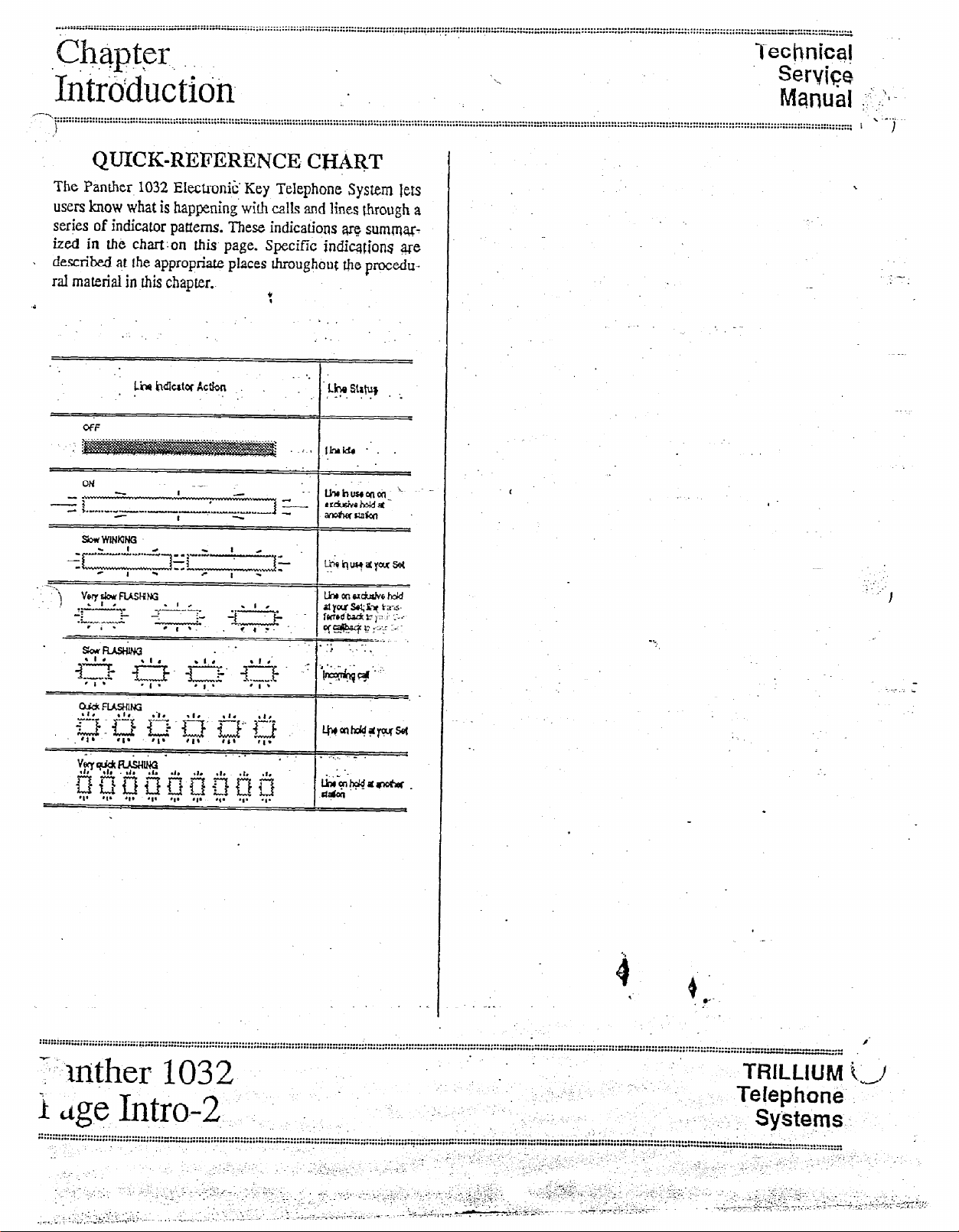
The Panther 1032 Electronic’ Key Telephone System leti
users how what is hapFning’with calls and lines through a
series of
ized in the chart:on this page. Specific indicqions @e
. described q.t tie appropriate places throughout the
ral material in this chapter..
indicator
patterns. These indications arq summx7
V
,
.
procedu-
‘.
LiihdlutorAcdon . .
. .
-_
!h stxtu)
:
. . ,-1. . . ,'.
I
-*.-.*............,.......,.,.....
~~~~......I-I.**...........,,..,..,..,.,.~”Y.
.‘“-“‘~‘-....--~-.~...-*~...........,......~.............................:......................“..........................................,......................,............,.~........~....
~~*~~~~~~~-~~~~.l.......~..............~..........~.“.......~..........~..~..-~.....~.............~,.,...,“..,....*~......,.,.“.......~....,.“~~”.”..~“.~~**,.~-~*~rr~r~~~~~~~~~,~“~~~~,,
-:~m[her 103 2
i dge In&J-2 . ... ‘. ; c; ‘.“’ -1. ” : ;.
., .;.
i :
.:‘.yj-:’ ,.;,
., :, ; .;,..-‘. ; ,‘:
.,....>,i .,.,; ,.._ *,,a .,.,L.r:::.:‘.-
,.
‘:’ .‘A, :.m-L;.--- T’... .,,- :,i ..,. :.-, -.
,.._..m,
.: .
., ‘“, .>.
..I .._ -,, ‘. .,
., . . . .
-:. ._::, . : _~_
., ., Y.
‘.., .;, _ ._ _ ..-i:.-~.--.l.-r-
.,
:
-._ -,L.‘,;: ;.. ! .- -: :,.
. ‘:: c .-:.
‘..I .,.‘. l,.‘,..,. ); .:;.,e ‘ii ,.,‘..‘,-::‘.,
,I.7;.‘l.:
._ . . . i ,-,, ‘.
_~, ..+ .-,
‘.
:, ,, .. ,_
-~ - ,-- -T-,L,--;I(T-r -.. .
.:. : _^
,., ,.
.., :;mj:& ‘!1;):. ,
‘:: ,~,<,>,:,.:.5~
‘_. .>.,-: ;, ._
,+*&&;<“T -,-.. ~ ..“\‘~,-.~.~-;.-:.-.~~“,-~~
.
.
‘,.
,.. -, .‘.- -... _ , ,
.,_ i,, ;;;:;;~<;j;;.‘l /:, ‘.:.I; :
_i
., .._ ._ .!.
‘1 I’ .1. ~.
.’ ‘y-‘.:
,-,. :.,;.~.’ I,
:‘>:-.-‘.- ::, .- ‘, -’ : ;.. ,_: ;,:,:j:& ,.:,: -:‘. ,; _ _‘. ,. _. .,
: . .
-.----..“--.....-.-~-.“--
/
TRILLIUM t.,!
Telephon&~
-. sy’stems
:
““-““‘“~*~~~~~.~~
.;..,;., ^, -- :“I .-.
.v,+-7.,--, $I+:;: ~::;vJ”< ‘l,‘,,: *. z--*---z y. I,/_ .I-~‘ I -:I,
:.. :
,,‘! 1.’ -, . ..‘.
I,: .:;. (
..i~..,;.:
j ;.,- ;.,,-
Page 7
. . . . ..I......
_ . . . . . . . . . . . . . . . . . . . . . . . . . . . . . -..;;::::::I:::::::::::::::::::::::::::
~ecnnlcal ”
...........,..,.........,..,.,........,.......,...........,....‘.,.............
Service
Mantial
YQ
.-.;.,,;~‘:~
“..**......” . . . . . . . . . . - . . . . . . . . . . . . . . . . . . . . . . . . . . . . . . . . . . . . . . . . . . . . . . . . . . . . . . . . . .._........................_............ _ .-...........
. . . . . * . . . . . . . . . . . . . . . . . . -.* . . . . . . . . . . . - . . . . . . . . . . . r . . . . . . . . . . . . . . . . . . . . . . . . . . . . . . . . . . . . . . . . . . . . . . . . . . . . . . . . . . . . . . . . . . . . . . . . . . . . . . . . . ............................................ :
\
itAD AND TELEVISION
_.
The Panther 1032 Electronic key Telephone
t
System generates and uses radio-freqtiency en-
ergy and accordance with these instructions - may,
cause interference to radio and television
reception.
The Panther 1032 Electronic Key Telephone System has
been certified to cotiply with the-limits for a Cl&s B com-
puting de&e, pursuant to Subpait J of Part 15 of the Federal
Communications Commission (FCC) Rules which are designed to provide reasonable protection from radio and
television interference in a residential installation. However
there is no guarantee that interference will not occur in a
particular installatiop.
INTERFERENCE
W~hVAJG
if not installed and used
:
in
strict
i.
.
c FCC
Requilrenknts
.-...... .
. . . . . . . ..-............. - . . . . . . . . . . . . . . . . . “..I .._........” . . ..--.....-..._._....” . .._......
HEAEUNG AID COiW’ATBILITY
The Panther 1032 Set is compatible for those requiring a
hearing aid as defined in section 68.316, Part 68 of FCC
Rules.
:::x::: :::::: ::
If ‘interference is encountered, test to determine if the unit is
K-‘.
at fault by unplugging the Key Service Unit (KSU) f?om the
.<..
.j-:
! walloutlet
.I;
.:‘ :+;:;;
‘i
If unpIugging the KSU retioves the interference, fry the folIowing corrective
the interference is eliminated:
l
Change the Iccation or position of the indoor re-
..., ceiiring antenna of the radio or television.
l
.
Relccate the Panther 1032 Set or KSU in relation to
the radio and television receivers experiencing
interference.
y
Plug the KSU into an outlet that does not also serve
radio or television sets.
If further help is needed, consult your TRILLIUM dealer or
an experienced radio/television technician - or refer io the
FCC’s booklet, “How to Identify and Resolve Radio-TV.
Interference Problems.”
Govemmen t Printing Office, Washington, DC 20402 (stock
number 004-ooo-00345-4).
.
measures,
-
It is available from the US
-
singly or iti combination, until
” . . . . . . . . . . . . . . . . . . . . . . . ..“.....” . . . . . . . . . . . . . . . . . . . . . . . . . . . . . . . . . . . ..I............ _ .-.....-...--........ _ . . . ..-.. * . . . ..-.-..._” . . . ..-.---.....-............................. _ . . . . . ..- _ . . ..-.-........ * ......
......‘.................,. . . . . . . . *- . . . . . ...” . . . . . . . . . . . . . . . . . . . . . . . . . . . . . . . . . . . . . . . . . . . ..-..................................
-.’ TRILfmiUhj
.~ i
. .. I> Tekphdne
~ $Mems
~:~m”:“:“‘-.-..“,..,-.” . . . . . . . . . I.” . . . . ““.“..“..“...” . . ..- I-I I.... .
.-.a-...“.” . . . . . -... . . . . . . . . . . . . I . . . . . . . . . “.I... . . . . . . . . . “..,.._I . . . . . . . . . . . . . “..“.“..“..” . . . . . . . . . . . . . . ...” ._......._............,.......................” ,........_ _ .__.___..___...
: ..,
. . ..-......_..” . . ..I..” . . . . . . . . . . . .
: -
. . . . ** ..-.-..................,...............,......,,..._ . . . . . . . . . . . . . . . . . . . . . . . . . . . . . . . . . . . . . . . . . . .
11
c’
irunei 1032
,.&e.&y
. . . . . . . . . . .._-_.___.-.--.---.....
.~
. I
. ..-- “_I . . .
.~
P
_-_ . . ,’
.
. . . . . ..-..................-.-..........” . . . ...”
_.
‘_ _ :.
::~:::z:.1:nm:“:::::::-:-:::::~
Page 8
Techpjcai -. ii:.):
..-...............-............................................................-................................................-.
:
..;l..,.,,I-..,,
.,__
:.*.,:,-:2
.--..
_.
.
.-, , r-.
._-:
FCC
R~~~i~&~ent~ .
.I -3.
;::::
: -,’
.-. >,..
, Seryice ...-' "
Manuai $: ,,..; '.:.
. . . . . . . . . . . . . . . . . . . . . . . . . . . . . . . . . . . . . . . . . . . . . . . . . . . . . . . . . . . . . . . . . . . . . . . . . . . . . . . . . . . . . . . . . . . . . . . . . . . . . . . . . . . . . . . . . . .
;-""'..... . . . . . . . . ...I . . . . * . . . . . . . . . . . . ..* . . . . . . .* . . . . . . . . . . . . . . . . . . . . . . . . . . . . . . . . . . . . . . . . . . . . . . . ..I............." . ..-" . . . ..._.._." .,...........,.._ "" . . . . . . . . . . . . . . . . ..." . . . . . .._........ _" ._..._... _ . ..-..._.................... ::"I::
\'
:'
I
RESPONSIBILITIES :
The FCC’s rules permit the Panther 1032 Eiectronic-Key
Telephone System to k coimcted to the telephone network
Ga a jack or jacks provided by the telephone company
:teIco). These jacks are not provided for coin or party lines.
User Responsibilities t
3efore connecting your Panthei 1032 Electronic Key
relephone System to the telephone lines, you must cop&ct
he telephone company and provide them wit!? t’ie following
nformation:
.
Telephone numbers of the lines to which @he
Panther 1032 Electronic Key Telephone System b
to be connected (lines 1 through 20)
l
FCC Registration Number (found on &e side of the i
Key Service Unit ordKSU: the number for be
Panther
l
Ringti Equivalence Number (also found on the side
of the KSU: the number for the Panther 1032 is
:“\ 33B)’
:.
1032
system
is EBS78T-71737~KF-E)
Telco Responsibilities
The telephone company is requirti to give you adequate no- ’
cite of any changes it makes in its technical operations or
proce&res that may affect the compatibility or use of your
Pmh 1032 El~Q-wid Key Telephone Spm.
:.
‘.
.
;.
i .,/
.:-
‘,.
. -L’
. . . .
:..
.’
..-:. ..:
I
;’
: -:
:, -.
,:-
:
‘.
. .
. .
. .
‘.
USOC jack required (usually one 50-conductor
RJ21 jack to the KSU)
l
Facility Interface Code (the code for the Panther
1032 Electronic Key Telephone System is 02LS2)
ou also have the responsibility to disconnect ZJ malfunclning Panther 1032 Electronic Key Telephone System
sm the telephone lines until the cause of the malfunction-
g is identified and repaired. Othenvise, the telephone
Lmpany may temporarily disconnect service.
GCanadian Department of Co?munications
r for the Panther 1032 Electroni
!6B. __
.--.-.-.-..--..-- . . . . . . . . . . . . . . . . . . . ..f. . . . . ---.... . . . . . . . . . . . . . . ..-........-.....-........ i . . . . . . . . ...” . . . . ...” . . . . . . . . . . . . . .
*.--.-a.-..--“-” . . . . -“-.-.““.-.- . . . . ._..“.” . . . ..--....-.. I .-... “” ..-........-....... I.“..” . . . . . rr..:,: .-................ t . . . ..-...-.
1,: I . . .
:_
c
tl-
ler 1032
< I
lag
.--.-..-- . . . . . . . . . . . . . . . -..- . . . . i..- . . . . . -..- . . . . . -...--..- . . . . . . . . . . . . . . . . . . . . . . . . . . . . ...” .I................._...........” . .._...” . . . . . . ..-............-.....-................ i . . . . . . . . . . . . . . . ..-...-..” . . . . . I
. . . ..“.-..-.“..-..I.....“.-..-..-...”..-..-” . .
A-2
: ‘-
.- . . . .-~ : ..:... .: ,:, . ,-. .:..:. -. :. :
. .
_ .,.: .-; ::. :. .k’&
-z:
d
Key Tele
,
. . . . . - . . . . . . . . . .
load
num-
hone System
0 ’
I we
. .
. . . . . . . ...” . ...” . . . . ...” ..-..
.
.
. . . . . . . . - . . . . . . . . . . . - . . . . . . . . . . . . -.. -...-..^_.............-..-....--...- “.
“... . . . . . . . . . . . . . . . . . . . . . . . . . . “I . . . . . . . . ..__.- “.“.“...“.” . ...” _..._
.:
:, ..
““--” ..--........... I ..-. _..._ ..--....- I..- . . . . . . . ...” ..-.-.-.... :.-.” . . ..-- “..~
.I..._ I .j.
.,_. . . . . .
.:. ..I
-.,-1.I :.,.;. ‘.;:J: ,:-, .::..> ..:; :-;*,;:!‘:~‘.’
, . :.. ” ;::.: (, ., , i..
_
,’ L dY.< : -.i, . . r .
,i: ! ,1 ,’ ,. .,.:, ‘.,.,,..,‘T; ‘.‘:ai;....“;.:::;:
,.
., ; ,.,
,, .. ;
-. ,. :
, 1 .~:,&.,i:.,:,,, .:., -,,, :. -: r -I’. ‘.
E T.&‘.,;.,; __. :.‘:.: . ..I. .,.. ;;, ~ ,;, ;;.;+z-‘;.:.“::..- L,. ‘: ‘.*i::...-.
.... :;. y.. ...... _.-_ .-r‘;:’ --
:..
/, ,’ ‘:-<
.;. .;
TRILLIUM i_I/
?‘e!ephone
.’ Systems.
--
. . . . . - U..............” _... “-
-“--“..“-“P...“.... . .._..” . .._._
.iy“:.,::; ‘I:
.;.~~~~;-~:!+
. .
1. ,. ..; ., .’
:, :f:‘:; ,._:; f--’ . .
s’
,* .
. . :
;.: :
_, ,;“..
,:. -
._
.:
. .
:
‘.Y.
-.
-.
Page 9
I ecnnical
...................,...
-...,....,,.......
Service
; .:,;,\ tmllial
-.i‘.
‘ ‘j : ;qi
.-y-k< . . ’
: \-
: .?
_............-........................ :‘..I.....
. . . . . . . . . . I...... . . . . . . . . . . . . . . . . . ..I...
ST&?Ih&D CQMPONENTS
One Key Service Unit (KSU)
Part Number 90-0285 (tone/rotary)
The Panther 1032 KSU can be expanded,
creating a Panther 2064 system, by adding.a
Panther 2064 expander KSU.
,. :
System
. .
Com~oiMGs
. . . . . . . . . . . . . . * . . . . . . . . . . . . . . . . . . I . . . ..I..................................-..” . . . . . . . . . . . . ““_“._.“.,_ . . . . . . . . . . . . . . . . . . . . . . . . . . . . . . . . . . . . . . . . . . . _” . . . . . . . . . . . . . I . . . . - . . . . -“_”
**..*.*.*.... . . . . . * . . . . . ..I............... . . . . . . . . . . . . . . . . . . * . . . . . . . . . . ..I............. ..,,,,. . . . . . . . . . . . ..-....... . . . . . *............*I. . . . . . . . . . . . . . . . . . . . . . . . . . . . . . . . . . . . . . . . . . . . . . . . . . . . . .. I ...... -
Near the bottom left of the KSU are four 50-pin connectors,
labeled STATIONS 10 TO 17ZOUD BELL, 18 TO 25,26
TO 33, and 34 TO 41 that are used to connect the KSU to
the station wiring main distribution frame (MDF) - and,
NOTE .
,. _’
through the l$DF, to all the system stations. The Iast pair of
1 the cabIe connecting to the. 10 To 17 connector is also op’ tionally available for connecting anzxtemzl loud bell or
oher sounding device through an external dry contact inter-
Face unit.
.
.
:::::::
,
I
The key service unit (KS~ for the Panther 1032 Electronic .
Key Telephone System can be programmed to operate with
either dual-tone, multi-frequency (DTMF)
signaling. The signaling‘on each Central Office (CO) line
can be programmed independently.
The KSU ha .--r:e 50-pin connector on its right side (labeled
CO1 to CO: .‘; 10 attach-t& ten Y:;,:~i:g Mephone company (telco) CU IineS (Iine 10 ;:::A be left vacant
optional Door Answer Unit is instailed).
The KSU also has on its right side one recessed light-
emitting diode (LED) indicator (labeled STATUS); four
. .
‘%q
miniature dual in-line package (DIP) switches (Iabeled, fi-om
;_ _,
top to bottom, 1 PROGRAM [used for feature program-
.!j
ming], 2 [not used], 3 [not used], and 4 BATTERY [used to
save feature programming]), and one recessed pushbutton
(la&led RESET).
Also on the right side of the KSU are connectors labeled
PAGE (used for external paging equipment), MUSlC (used
- for an external background and on-hold fnusiE tome),
SMDR (used for the optional SMDR unit),XWER FAIL
(used for the optiod Power Fail Transfa Unit), ;dnd DOOR
(used for the optional Door An&er Unit).
or
rotary (PuIse)
if
’
the
NOTE:‘70 allow for future groivth, two connectors are
a&able at the bottom of the KSU that are used to add an
: exptiion KSU - when converting your Panther 1032
tern into a Panther 2064 system.
The KSU’s power cord (at the top of the KSU) plugs
110 V ac outlet (but only at the appropriate time; see the
Connection Procedures section). A grounding wire. (12
AWG, solid copper) which connects to the top of the KSU
:
must be attached to a ground clamp, usually on a water pipe.
An input connector (Labeled EXTERNAL BATTERY) for a
24-V dc backup battery is aIso provided at the top of the
KSU. If ac power is lost, the switchover to battery power is
automatic.
.Tbe unit comes with 4 screws for mounting the KSU on a
tidCbOd
into
sys-
a
““..........“...-....-..“..-..,,,.;, . . . . . . . ..“..I...-...... . . . . . . “..... . . . . I.... . . . . . . . . * . . . . - . . . . . . . . . . .,“._.l.L........_ .-.. L -.-,.. I . ..*. ~ ,.........................
‘....... . . . . - . . ..I.. 1.-...--....” . . . . . . ..I............. . . . ...” . . . . . . . . ..I................ ss . . . . . . . . . . . . . . . . . ..I....” .-.-.....,.....,......-.........” . . . . . _ . . . . . . . . . . . . . . . . . . . . . . . . . . . . :” . . . . . . . . . . . . .._...._.................-. L _.._..___..............-
: .TRILLIUM
( .. j. Tekphetie
‘_
Systems
“.......L.“...“,
““........-. . . . . .
.-...-a...~,.~......“.... . .
. ...” . . . . . .
. “.......,...,.... . . . . . ..1................“...“... . . . . . I . . . . . . . . . . . . . . . . . . . . . - . . . . . . -.- . . . . . . . . . . “--..“^I”-- . . .
.‘. ’ 1
.‘,
;.:~,<-..;.,, ,.y-, .:<;-; ,..$, .‘I. .I I-; r .,:s..;;>z, .,>. ,
. .:.::.,, I,
_.. ._.
__
.;; .: ;;. “.: ,..‘, “-,l.~ll, ,.y.-&..--;. . 7. ibY. V,Fl
,. ;. . .,-Q,. . .
., .,.*’ . . .
. . . L........” . . . . . . . . . . . . . . . . . . . . . . L...;, ..---.-..
,c;,. i I__ ~
i,- l., ; . :,;‘..i .:.;-- *,:,,.“i’L1 .,_ . ..-
:
:
. . ._ .- .’
: :;:,;;:
.
.-, ,’ :- ::-‘ic,; ,;:;;;,.:;.: ‘,..,.. :;., 5;; :: ,_ ;:.
I. ,: _:, ,!‘:+.&;;~;;i;,,. *\ - _
1 “,, ,:
~,-;, -.
.; ‘/
_.... . I ./ _( __ .,
‘,.; :; ,... ;.:
.;..:-.- -., ., :,
-,. _., ,:,.”
_..
:
_____I.__-..*.*...*...-.” .
..........,...._....-...” .......-__ _ .__.._.. “..” .._... “._
Panther 1032
.‘I Page B-l .,
. . . . . . . . . . . .A...,,, ,_...
. . . . . . . . . . ...” . . . .
,‘..I ,.; _ ,:. .!
;. ..‘, ., f’-‘ ;.::1 ‘.;.:-.
,...; ”
,.
;, I,.>~~>>---:..;:..,‘7 ,-,(- .r,‘.;:.;; ~, ,.,. “., ,,- i, 7 -^z:l”i, -: -‘..‘v,.’ ‘-
.-~-L+.:
. . . . . . . .._.._......” . . ...” .
.’ :
: ;-
. . . . q..-~,m-:..g
.- .-
“.
I
_.
Page 10
:D::;::~“::~;‘E~-““““” . . . . . . . - . . . . . . . . . . ..._..” . . . . . . . . . . . . . . . . . . . . . . . ..-.
.,.)............._l(-.....,.....,.....-....
‘“““.....“.~.“....“...........‘................................,.......
-.--“.--....,..“....-._I_- . . . . . . .
. “.t ..,...... I ^.,...,..,., _.” ..__” . . . .-.....-- . . . . . . -*“-...-.-..I.- . . . . . . . . . . . . . . . . . . . . . . --.-.- .,.............._............... . . . . . . . . . . . . . ..r.. - . ..._..” .,...” . ..__......_.._.-....
.
. ..-......
. . . . . . . . . . . . .
. . I..._ . . . . ..-... “...-.L . . . . . . . . . ..I.....” . . . . * . . . . - . . . . . . . . . . . . . . . . . . .
--.--.-...:“‘:::;:::::p
SjWm
,’ Cdhtionents
‘. ““) . . . . . . . . . ..*..............................
. . . . . ..‘.‘*...‘..‘.-..............“.‘......1”.............-..‘3..’.. . . . . . . . . . . . ..I.......I..UO . . . . . . . . . . . . ..“.............. n . . . . . . . . . . . . . . . . . . . “...r;.,r ..).., “..“.)” .,.,........,,; .,..,.,.,,...... I . . . . . . . . ...”
‘Up to Thirty-Twti Telephone Sets
Part Number 904320
(non-handsfree) :
grt Number 90-0321
(handsfree).
Other than the handsfree operation, these two models look
alike
and operate. identicalty, For eqnple, b* have m at-. ’ ‘-
b-active black matte fish.
Each Set’s base has ten line select keys (labeled 1 through
JO), eight dedicated function keys (labeled
Cancel, Conference, Intercom, Redlal, Speed,
Speaker, and MiC.on/off)
‘. The
line keys, the
haveqcompanying stat&indicators.
. . . . . . . . * . . . . . . . . -. . . ...” . . . . . . . . . . . . . . . . . . . . . . . . . . . . . . . . . . . . . . . . . . . . . . . . .._._............................ ” . . . . .
Up to Sixteen DSS/BLF
Part Numbq 904412
The DSS/rjlJT QI-GE haq 32 key3 and indicators, labeled 10
through 41 -one for qa+ possible station in tie system.
The DSS/BLF unit-Set
lion .ws
allow the user/attendant to seleq the .desired station by
‘.--_. pressing qe of the 32 direct station select (DSS) keys and lo
obsen9 @ status
spending busy Iamp field
,The DSS keys can also be programmed to select
numbers - keys 10 .Lhrough 19 can be used to dial the first
ten’of
-, 20 through 41
of
qe system’s 80 common
through&).
and a tone dial keypad.
Intercom
*
key, and the
‘ .’
Hold,
Flash/
MIc.on/off
key
_
. . . . . I . . . . . . . . . . . . . . . . . . . . . . . . . . .
pairs (also known as attendant sta-
-but not to & confused with the master station)
of each station by
(BLF)
indicator.
the auendant’s private speed
can be used (.o diaI the corresponding first 22
speed calI numbers (codes 20
Technicas ii
Service
lmnual ‘. .,j_
Units
observing the cone-
speed call
call numbers; and
,l I
,
.
’
* ~.
.
keys
l5x~IIy, the base has a speaker
justment) and a ringer
volume con&of (a sliding 2:;.
control
switch (a 3-position SW?.
--for low, medium, and high volume ringing).
‘<h Set also includes a teIephone handset and two modular
ds - a’4-conducr.q coiled cord
set to the Set,
and a 4-conductor modulti cord fc$
for connecting the hand-
connecting the Set to the stafion wiring jack.
These‘ units
- which require an accompanying Se-t - are
assigned q s@ion nuqber and, therefore, reduce the mqxiRIXX number
of
sets possible on a I-for-l basis.
FM example, a system with a single DSS/BLF unit
PpId lqye a
pin43 with the DSS/BLf; unit).
maximum
of
31 S&s
(including the
‘.
.. .*_
Alt&ativeIy, a system couId have as
. l+F u.njt.S, # rq+ing an,zcompanying Set; this sys-
many as 16 DSS/
;. tern would -have exactly. 16 Sets, each &-t. df an
’ :. atte&t &i&l.
.
: Each D!&BLF
._
_ Connecting the unit to fie statiqn w&$@ jack
Each I+S/BLF
Card
(used to record station Iocations/assignment) - and
w$h a plastic cover that protects the Designation Cad.
tyi!
includes a&xnducq
mc&iar
unit also comes equipped with a Designation
cord
‘. I
Set
:
for
. ..-..-- . . . . -..- . . . . . . . . . . . . . - . . . . . . . . . . . . . . . . . . . . . . . . . . . . ..-..........................
I....* ..,... I...
I-“lnther
F
kage.B.-2 .#. .~,. ‘.I,
--...-.--...--- . ..I....... ^ . . . . . . ...-..” . . . . . . . . . . . . . . . . . . . . . . .
m.““.“..rr . . . . . *..*a...** .
_
1032
. . . . . . . . . . .._- “.” .
’
: ;/,, ..,.,
--.
. ..__ “.“..:.“:::~;:p;;“‘:=::::::=:::“::: ::::::::: i :::;:::::
.
.
. . . . . . . . . . . . . . . . a..*...* f....... . . . . . . . . . . . . . . . -” . . . . . . . . . . . . _. .,.. :::::*‘:::::::
. ‘.
.. _,
. .
.; . - ‘. ..
y:, ; ..,
‘. -.
..: . . . . . ..I.....-...... _ . ..-.......... * . . . . . . . ...” . . . . . . . . . . . . . . . . . . . . . . . . . . . . . . I . . . . . . . . ..*...___...
. . . . . . . . . . . U” . . . . . . r’” . . ..-.. “I.-.- ..*...........................,....... “,.r,,.::::::::::.::::~.~ . . . . . .
‘_ ; -. 7
.L :... .’
.-, .
,,~: .‘~,..b,‘, .-
-.
i .,.L
_ _ - / .,‘. .,.-.
-.. ..
,a:.
1.
,
, ,,.. :
. . . . .--_---,-
., .“.
, ,..,“’ .; .,., i . . . . :Ijl‘ .i..“l I-7 ..- ..
yis;l!;
..- . . . .
. .
e
. . . . . . . - . . . . _-
. . . _.._” . . . . . . “.
: ‘: ::
,.
Page 11
i’:.@; ,’
.!:! ;:I :$,: ,’
- -.i.z::. i
.’ :
’ Tech tt icaf
service
. Manrial
_L :!
-..........; . . . . . . . . _ . . . . . . . . . . . . . . . . . . . . . . . . . . -.-...-.--.... . . . . . . . . . . . .I.. ..,..... . ..I.... . . . . . . ..,.......I.. “............................,....” . . ..-............... “...~ . . . . . . . . . . . . . . . . . .._...........“. ,” . . . . . . . ..““..._...-...-..” .“...._“.. I*I...
. . .I.... .1,,...*..1.1..*1......... f......“. . . . . . . . . . ..*-.a.* . . . . . . . . . . . . . . . . . . . . . . . . . . . . . . . . . . . . . . . . . . . . . . . . . . . . . . . . . . . . . . . . . . . . . . . . . . . . . . . . . . . . . . . . . . . . . . . . . . . . . . . . . . . . . . . . . ..................-..... ”
1
..: :. ‘.
system
Ccmq$xieGts
......,. ... ..., . ..... ... ....,.............., .,.. ..... . ....... . *..... :..,
.,”
OPTIONAL COkPONENTS ,
One Door Answer Unit,
’
Part Number 904058;.
With One or Two Door.IQodules,
Part Number 904057
The Door Answer Unit (also known as the Dozr Answer
Control) is installed next to, and connects with; the KSU. It -
serves as the interface between tie system’s stations and tie
one dr two installed Door Modules (also know as the D&r’
Answer Bqxes) at the c&red doors br entryways.
Together, t&se units enable signaling and conversation be-
tween Set users and v&itors. Like the KSU, these units come
equipped with mounting screws.
A visitor, by pre ~- ing the door bell on a Door Module, gen-
erates a distine~ 2: tone (four groups of 4 short t&es for
Door Module f& groups- of 2 long iones for Door
Module 2) that will sound at all Sets programmed to ring on
line 10 and line f0 indicator WINKS, Also, each Set user
,* ,+; can generate a tiling tone that will sound at Door Mcxlule 1
.‘$t~$
only.
‘, \
I
.
Up to Three Power Fail Transfer Units
Part Number 904052
Up to 31 Off Premises Extension/
Data Interface (OPX) units
Part Number 90-0308
The OPX knit converts a 2,wb-e interface to a Z-wire irtJerface, ailowing a single line telephone to be connected to any
spare station jack - except station 10. It also allows Z-wire
devides to be connected at a distance greater &an the system
2000 feet limit for Sets. The OPX unit also simuIates CO
line chqcte<s+s, $lowing a mtiem or an answering ma-
chine
to be connected to the system. Finally, the OPX
..’ allows a remote device to beconnected to your system at
agy distance via a CO line.
When the user lifts the.single-line telephone’s hands& an in-
tercom connection is made 10 the Pan&r system. Also, by
dialing a speciaf code, the off-premise user can access any
of the Panther system’s outside lines.
unit
One Station Message petail Recorder
-(SMDR) Unit
Part Number 90-0227 only
This unit allows information on system, line, and station
usage to be captured and redorded;
’
.
The Power Fail Transfer Unit automatically takes over in the
event of an electrical power failure, allowing for continued
telephone service during the emergency, One Power Fail
Transfer Unit can handie up to 4 incoming liries.
When power fails, the Power Fail Transfer units transfer
coming CO lines {up to all 10 of them - or the 9 lines in
use, iE the optional Door Ahswer Unit with Door Modules is
%alkd) to pre-installed standard telephone sets (not to
Panther 1032 Sets).
l
, .
in-
.+,
0
-
,
0
. *?’
Page 12
~::::::::-‘::;;::;::=;:::;::::r:’::L’: . . . . . . . . . . . . . . . . . . . . . . . . . . . . . . . . . . . .._..
..~......I.......................
:.::::::‘::::::::::.~::::::::::::::”:i:::::::::::~:::~~:~::::~::::::::::::::::::::::..::::~~~~::::::~~~~-~
:
Sys*iern :
.Coi-nponents
. . . . . . . . . . . . . .
‘1
j
* .I... I . . . . . . . :::::::::::::::::::~~~~:~:::::::::::::::::::::~:::::::~~:~::~::::..~ .,.‘!,,,.,,,!~. . . . . . . . . . . . . . . - . . . . . . . . . . . . . . . . . . . . . . . . . . . I . . . . . . . . . . . . . . . . . . . . . . . . . . . . . . . . . . . . . . . . . . . . . . .
3 . . . ...” . . . . . . “I.” . . . . . “..# . . . . . ?..? ,,,,!, :,“, ,
. . . . . . . . . . . . . . . . . . . . . . . . . . . . . . . . . . . . . . . . . . . . . . . . . . . . . . . . . . . . . . . . . . . . . . . . . ~ . . . . . . . . . . . . . . . . . . . . . . . . . . . . . . . . . . . . . . . . . . . . . . . . . . .................................................-..
a.
.!,,,“..,,....p.‘.~.“....~.!.,.,~...,”~.”.,”~~- ..“,. C-rr.,rrr:: ..-. . . . . . . . . . . . . . . . . . “I” . . . . . . . ..I. *-..CU--“..” .,,.,,. _
. . . . . *‘..T~,.l* . . . ..I. s,.:..
.- . . . . . . . . . . .“.,,..“.” *..,,*.......,,.,, “...I .,.......,..............,.......-..... I . . . . . . . . . . . . . . . . . . .
TechnjGal
Set-@32 ,,, 1,.
NtatJua[ ‘:I ;;;A
..-....................................-........ , . . . . . . . . . . . . . . . . . . . . . . . . . . . _...” . . . . . . . . . . . . . . . .
: . .,
Set Stagdsmall-Mobnts
Part Number 90-0087
Each Set may be placed on a desk - or ri~ounted in a-wall
using the Set S taWWaU-Mount Bracket (available. @I pack-
ages
of10).
The same braeke; can also be used to provide a heightened
viewing angle when used with che%et on a desk- or table-
top.
-..
.
“1
:
.
Desigrlation Cards
Part Number 90-0258
(for Panther 1032 Sets)
and
Part Number 90-Oi59
(for DSS(E&~ pnifs)
The Designation Card for Sets (the same Designation Card
is used for lxxh r,on-Iirindsfree
list the telephone numbers of rhe incoming lines and to identify the assignment or location of the 32 system slations
(numbered 10 through
A$hodgh each Set comes equipped with one instalIed and
one spare Designation Card, you may order ad&.ional cards
(in pa&ages of 10) for your system.
The Designation Card for DSS/BL?? units is u&xl to identify
the assigriment or location of the 32 system stations (numbered 10 through
- the first IQ private nqrnbers in spaces IO tl-qough 19 and
the fit 22 common numbers in spaces 20 thrpugh
Mthough eztch DSS/BLF unit comes quipped with one in-
stalled and one sparg;“ Designation Card, you may o_rder
additional cards {in packagq of 10) for yoq syqem.
41).
41)
and for recording speed call numbers
and
ha&free Sets> is used u)
41.
.
.
::. : ‘.-
I 7.
.!
Notice that the. Set and the DSS/BLF unit use dz$%renr
,:.
I+xignati&C&s.~ .
. . . . _
.::::y:; . . . . . . . . . .
[ .-‘:‘rlt&
pilge. B-4 -’ _. ;,’ : ., -‘,,
..---.- . . . . . . L. . . . ..I.............. . . . ...” f..................... ~ . . ...“...........“.” -._.........; . ..*.
“.“..~“~......I.~“....... . . . . . . *-....“.“..I . . . . . . . *.... . . . . . . . . . . . . ...” . ..-- “.““.~” .,.....
,,:..,<,::y..,y.i.~ . . ,: .>. zi :‘.-..
. . . . . . . . . . . . . . . . . . . . . . . . . .
..*...‘.‘...‘.......................-.-.....””............... . . . . * . . . . . . . . . . . . ..“.......~ . . . . . . . . . . . . . . . . . . . . . . . . . . . . . ..I..... . . . . . . . . . . . . . . . . . . . . I . ...“. c . . . . . . ...” .,.. . . . . . . . ..“.“..1.... . . . . . . . ..I...” . ..“......_-
.- . . . . . . . . . . . . . . . . . . -..- . . . . . . . . . - . . . . . . . _ -..............,...,........,.,..,...,...,,..,.........................................................,................................“.,...,... ,,~-; ,....,._“._ “.” -._*
1032
:;-
.. Tf$$;;;
,-
,. .,-’ ,:;.; ~..Z. ..
“. ‘.. .: ,~
.:.
:’ I’.. .,_
: .“.‘l .,,,,I. ;:~:..,;:.1’ ‘L; ,;_:
‘. .,,, i ., ..*..f. .’
,,L ..‘l/l ;.“,.;‘I _,..,_. :;->-;--, “+~;:,‘;‘~ -, : ,$ -.: -“‘.:,-‘- :y ; ”
: ~ -.‘.,_ ,..,
.yy., ..I ;2; :.,.. ..,
d...FT-.
_’
,’
.,.
^. ~- ,-...-. ,I~.:’ -. :, ._.
1’ _ (- ,-. . I , . . . , .,,i ~;~.~‘crr.‘.l-.kr:;‘:.~~~~.‘~
I,,,,.
,,,i.-::;,;~.‘i~~,8i:‘~l’:i::J-i.-
:
.I
:
-
_, . .
. _;
/ ,.=,,.,,; L. ::--1--:. ,._
,. ‘. :,
~\.;>&:i::7:;‘!> :!:!. LI ~‘L-
/
_’
_- ,:
TRILLiUM (-J
. . . . . , .-....,..,.... I.” . . . . . . . . _ . .._.
. . . . . . . . . . . . . . . . . . . . . ...“.. . . . . ...““.
,,.~ ~:,: :,. . ..,’ _--..,, . ..I. :. : ., .--> ;x:: : 1 . . . . .
“-...U........“..
;
_ ‘.‘r:,:i,:‘“‘- .
Y
-,
Page 13
Technical
~..--...“,,,~;.,,,,i;;m::~~:::~:~~~~~:~~~:::~::=::~~:~~::~~:~:~:~~~:.~:~~~~~:~:~:::::::::::~:~~::~::~:~:::~~::~:.::~::~:~~:::::-~::::~~::::~:~::~:~:::::::
Service
- .Nantial
‘1
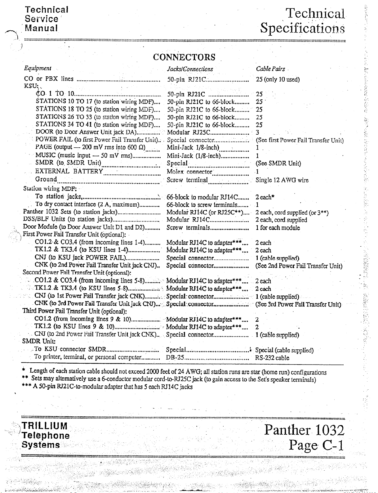
Equipment
CO dr PBX lines
KSU: . .
$0. 1 To 10
STATlONS 10 TO 17 (to station wiring MDF)....
STATIONS 18 TO 25 (to station wiring MDF)....
STATIONS 26 TO 33 (to station wiring .MDF)....
STATIONS 34 TO 41 (to station wiring MDF)....
DOOR (to Door .Answer Unit jack DA) . . . . . . . . . . . . . . .
POWER FAIL (to first Power Fail Transfer Unit).:
PAGE (output
MUSIC (music input - 50 mV m-6) . . . . . . . . . . . . . . . . . .
SMDR (to. SMDR Unit)
EXTERNAL RAT-TEKY
Ground
............................................................
station wiring MIX
To station jacks
To
thy contact interface (2 A,.maximum). ............
P&her
DSS/BLF
Door ModuIe (to Door Answer Unit D 1 and D2).
1 .
‘--“‘j First Power
...
Second Power Fail Transfer Unit (optional):
Third
-SMDR Unit:
1032 Sets (to
Upits
Fail
CO1.2.& C03.4 (from incoming lines
TKl.2 & TK3.4 (to KSU lines l-4).
CNJ (to KSU jack POWER .FAlJL). ....................
CNK (to 2nd Pokier Fail Transfer Unit jack CNJ) . .
. .COl.2 & C03.4 (from incoming lines 5-8).
TK1.2.& TK3.4
..
: CNJ (to 1st Power Fail Transfer jack CIW).
CNK (to 3rd
Power
Fail Transfer Unit (optional):
COl.2 (from. incoming lines 9 &
TK1.2 (to KSU lines 9 8 10) . . . . . . . . . . . . . . . . . . . . . . . . . ;..-:
CNJ
(to 2ncl Power Fail Transfer Unit jack CNK)...
..To KSU-connector SMDR . . . . . . . . . . . . . . . . . . . . . . . . . . . . . ;.. Special
To printer, terminaJ, or personal computer .,..........
. ..‘.“. . . . . . . . . . . . . . . . . . . :. . . . . . . . . . . . . . . . . . . . . . .
. . . . . . . . . . ..*......................................
- 2CQ’mV rms into 600 Q)
......... ....................... . ..
...................................
(..............................................
station
(to
station jacks). ............................
Transfer Unit (optional):
(to
Power
jacks).
KSU
lines 5-8). ............... A; I
Fail Transfer Unit jack
.
CQNtiECTORS
JacksiCmnections
50-pin RJ21C.; . . . . . . . . . . . . . . . . . . . . . . . 25 (only 10 used)
I
50-pin RJ21C ........................
50-pin RJ2lC to 66blczk ......... 25 ..
%-pin RJ2lC to %-block..
50-pin RJ21C to 66-block.. ....... 25
SO-pin RJ2lC to 66block.. ....... 25
Modular RJ25C.. ..................... 3
Special connecter.. ......... . .......... (See fiit Poker Fail Transfer
. . . . . . . . .
..........................
.........
14). .........
....................
...... .:.
....... :.:
CNT)..::...Special_connector
10) . . . . . . . . . . . . . . . . . . . ~~Mddular~14C to adapter*** . . . .
Mini-Jack l/8-inch)
Mini-Jack (l/g-inch). ................ 1
Special
MoIex connector.
Screw terminal
i,
66block to m&&r RJ14C.. ..... 2 each*
66block to screw terminals.. 1 . ......
l&duIai RJl4C (or RTiSC**) .... 2 each, cord supplied (or 3”‘)
Modular RJ14C.. ............. ;...; ... 2 each, cord supplied
Screw terminals.. ..................... 1 for each module
Modular RJ14C to adaptefltf.... 2 &
hkxhlar Rtl4C to adapter***....
Special connector . . . . . . . . . . . . . . . . . . . . . 1 (cable supplied)
Special’ connector . . . . . . . . . . . . . . . . . . . . . (See 2nd
I&duIarRJ14C to adapter?.... 2 each .’
MociularRJ14c to adapter+**....
Special: connector . . . . . . ;...; . . . . . . :... 1 (cable supplied)-
hlodular lZJ14C to adapter?? . . . . 2
Special connector . . . . . . . . . . . . . . . . . . . . . 1 (c&e suppIied)
DB-25
...................................
. . . . . . . . . . . . . . . . . . . . . . . . . . . . . . . . . . . ;
a.........._..................-..... RS-232 cable
..................
......................
...........................
. . . . . . . . . . . . . . . . . . . . .
Cable Pairs
25 ...
....... 25
1.
(See SMDR Unit)
-1
Single 12 AWG wire
2 each
Power
2 each
(See 3rd Power
2
SpeciaI (able supplied)
Unit)
Fail Transfer Unit)
Fail
Transfer Unit)
i
.)’
,:
,
::.
._
.‘.,
‘..
:
;.
.>
.:
. ...’
1.
:
. .
‘: ‘,
.:.
- .:_
t,
I..
i
:
:i:
. ._-.
. .
;: :
.:-.
:. ..:
_ -:
.‘_
* Length of each station cable should not exceed 2ooO feet of 24 AWG; all station runs are star (home run) configurations
** Sets may alternatively use a &conductor modular cord-to-RJ25C jack (m gain access to the Set’s speaker terminals)
*** A X)-pin RJ21C-to-modular adapter that has 5 each JU14C jacks
\
.._
.-...-,-“-..““-.1.....-...--~..“.-....- . . . . -L . . . . . . . . . . . . . . . . . . . ..-.....” . . . . . . . . . I._.._“.___ . . . . ._...“...I.._ . . . . . I.__.” . . . . . . I . . . . “- . . . . . - ..--.. -” . . . . . _ . ...*.. -- . . . . . . . . . . . . ..._....” . .._
. . . . . ..I . . . . . . . . I . . . . . . . . . . . . “I.....” . . . . - . . . . . . . . . . . . . . - . . . . . . . . . . ...” . . . . . . . . . . . . . . . ...” . . . . . . . . . . . . . . . . . ._“.“.“..1...” . . . . . . . “...__“..I._... . . . . . . . . . . . . . . . . . . . . . . . . . . . - . . . . . . . . . ..I................ - . . . . . .............._............”
: :
.‘.
.
i ‘::jTRiLLIUM ;
“:- ‘Telephone
-.-.SysteMs
-13
---....-....“...“,”
.
. . . . .
.,,Y .:..
Panth
.. Page.- -
Page 14
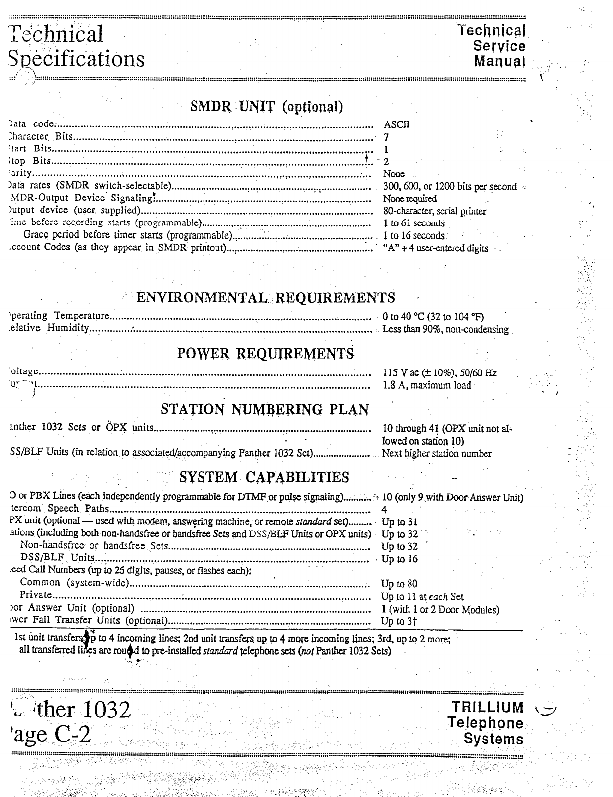
SMDR JJNJT (optional)
3ata code; . . . . . . . . . . . . . . . . . . . . . . . . . . . . . . . . . . . . . . . . . . . . . . . . . . . . . . . . . . . . . . . . . . . . . . . ; . . . . . . . . . . . . . . . . . . . . . . . . . . . . . . . . . . . . .
Character Bits
.,......................................................:....,..,.......................................
‘tart Bits . . . . . . . . . . . . . . . . . . . . . . . . . . . . . . . . . . . . . . . . . . . . . . . . . . . . . . . . . . . . . . . . . . . . . . . . . . . . . . . . . . . . . . . . . . . . . . . . . . . . . . . . . . . . . .
itop Bits
‘srity
Data rates (SMDR switch-selectable)
,hlDR-Output Device’ Signaling!
Output device (user, supplied)
. .
~me before recording starts
ccount Codes (as they appear in
. . . . . . . . . ..f..................................................................~.!................‘....‘.......
. . . . . . ..“......““...............................................................~.~.......~...........~....~...
. . . . . . . ..“.................~..........~............~....................
. . . . . . . . . . . . . . . . . . . . . . . . ..~~..................~...............................
. .
..,..............................,...................................................
(programmable)
Grace period before timer starts (programmable)
SMDR:printout)
“....“...,..~‘~“............................................ -Ito6lseconds
. . . . . . . . . . . . . ..-..................~.................. 1 to 16 seconds
.
. . . . . . . . . . . . . . . . . . . . . . . . . . . . . . . . . . . . . . . . . . . . . . . . . . . . . . . ’ “A”+4 user-entereddigits
t-;
-. ENVIRONMENTAL REQUTREMENTS .
)perating Temperature
.eIative Humidity . . . . . . . . . . . . . . . . . . . . . .._..........................................................................
~.~.~.~.~.“~.~.~.~..........~.....................~~...........................~........... ~0t040”c(32t0104”F)
ASCII
7
:
None
300,600, or 1200 bits per second
Ncmerequted
80-character, serial printer
Less than 90%, non-condensing
.
‘i
‘,. -.
, ,:
‘... .,
.:.
‘. -. .- ,
.
:
. . ...’
_;
POW433 REQUIREhfENT%:
.oItage
. . . . . . . . . . . . . . . . . . . . ..-.......................~.................................................................
-‘t
UT.
. . . . . . . . . . . . . . . . . . . . . . . . . . . . . . . . . . . . . . . . . . . . . . . . . . . . . . . . . . . . . . . . . . . . . . . . . . . . . . . . . . . . . . . . . . . . . . . . . . . . . . . . . . . ..-..
3
115 V ac (5 lo%), 50/60 Hz
1.8 A, maximum load.
STATIOi NUMj3@RING PLAN . -.
anther 1032 Sets or 6PX
SS/BLF Units (in relation. to associawaccompanying Panther
0 or PBX Lines (each inde&ndently programmable for DTMF.or pulse signaling) . . . . ;...;.:.I-
tercom Speech Paths
PX unit (optional -
used with modem, answering machine, or remote S&JI&U~ set) . . . . . . . . -
ations (m&ding both non-handsfree or handsfree Sets and DSS/BLF Units or OPX units) Up to 32
Non-handsfr~ o.r handsfree. Sets
DSS/BLF U.nits
. . . . . . . . . . . . . . . . . . . . . . . . . . . . . . . . . . . . . . . . . . . . . . . . . . . . . . . . . . . . . . . . . . . . . . . . . . . . . . . . . . . . . . . . . . . . . .
eed Cd Nuders (up to 26 digitq’pauses, or flashes each):
Common (system-wide)
Private
. . . . . . . . . . . . . . . . . . . . . . . . . . . . . . ..*..........~...............................................................
!or Answer Unit (optional)
lwer Fail Transfer Units (optional) . . . . . . . . . . _ . . . . . . . . . . . . . . . . . . . . . . . . . . . . . . . . . . . . . . . . . . . . . . . . . . . . . . . . . . . . . .
to 4 incoming lines: 2nd unit transfers up Q 4 more incoming lines; 3rd up to 2 more;
are rou@l to pre-installed
units
.
. . . . . . . . . . . . . . . . . . . ..~~.~......................................................
. -
1032 Set) . . . . . . . . . . . . . . . . . . . . . . . . Next higher station number
.. SYSTEM cAj?qBILITIEs
. . . . . . . . . . . . . . . . . . . . . . . . . . . . . . . . . . . . . . . . . . . . . . . . . . . . . . . . . . . . . . . . . . . . . . . . . . . . . . . . . . . . . . . . . . . .
._.........._.............*.....-..-..........-................-.......-.. Up to32 -
.
. . . . . . . . . . . . . . . . . . . . . . . . . . . . . . . . . . . . . . . . . . . . . . . . . . . . . . . . . . . . . . . . . . . . ..-.............
. . . . . . . . . . . . . . . . . . . . . . . . . . . . . . . . . . . . . . . . . . . . . . . . . . . . . . . . . . . . . . . . . . . . . . . . . . . . . . . . . . .
‘_ ..’
smdbrd
telephone sets (WI Panther 1032 Sets)
10 through 4J (OPX unit not al-
lowed on StatiOxJ JO)
- . -
10 (only 9 with Door Answer Unit)
4 .:
Up to 31
. Up to 16
up to 80
Up to 11 at each Set
1 (with 1 or 2 Door Modules)
Up to 3t
;.
.,:.
- I
-..
,.
-.
;‘.
.-
./ ._..
‘:
.....................................
.-...‘f-..““-” . ..“. .......
I. -\
..-......- ..;.
“““.^---
..
. ..-
I_. .._. i -_ ..- ^.
. . . . . . .. . . ....
k,&ther 1032
‘age C-2 1: _..,
.: .,.
........
^. .... . I.. .. ..-. “““.
- ........ --.,*,,“.-. ...
.............
.” _._.“. .......... ..-
“I.“.-._- . ..”
..:., ,
......
.....
c.
....
...
-.
-...-.._
“rn-~ . ..“..” .... “..rn.... .......
.
..
,........... . ..^......”
,r..,.r,r...n.“~..““...“~-“,“~. . . . . .Y.. . . ..._” . . . . . .._._
........................
. ..“.
..-.
....................
-.-I..
O”“..“..
.. . .......
- ..-.....-_ ... .._
-..-.-- - .-._
TRILLIUM is/
Te.lephone..
‘, Systems
. . . . . . . . . . . . 1.-.- ..-....-........._..” . ...-.., “._
. .
.,-
Page 15
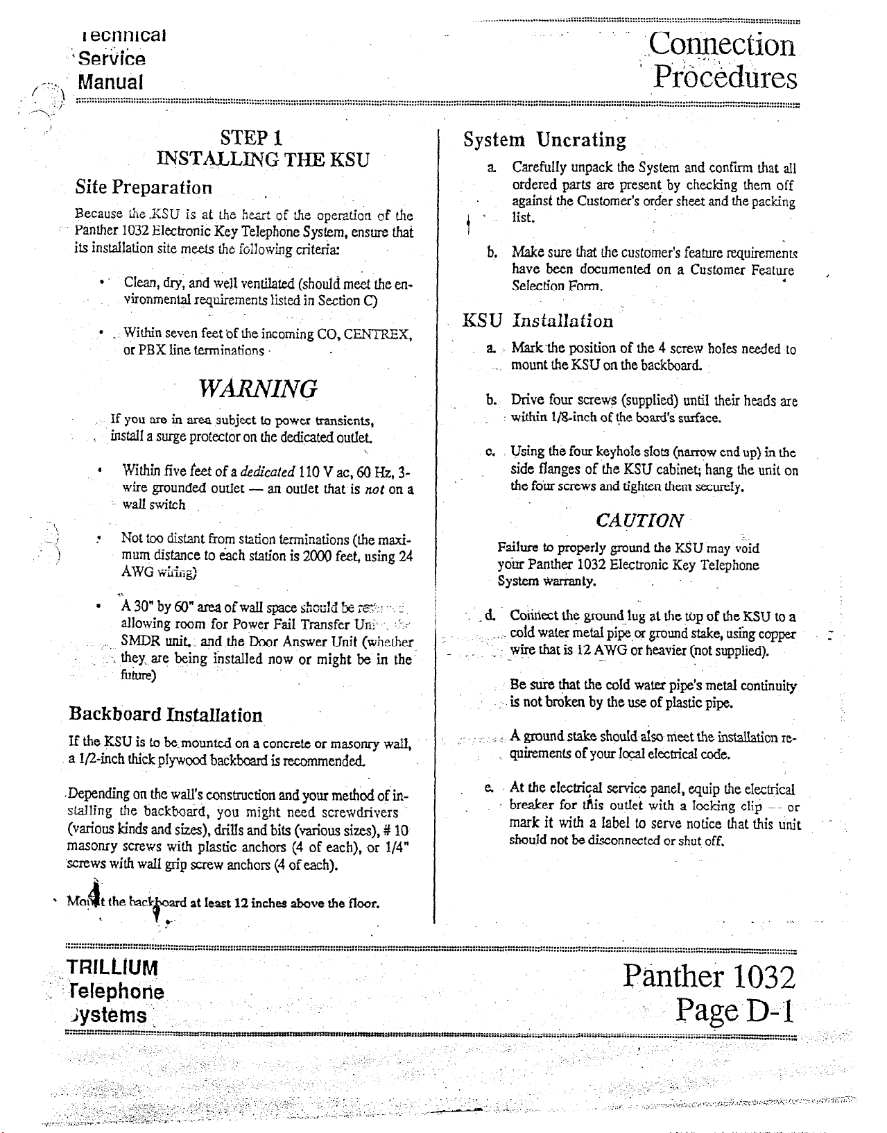
I ecnnrcal
’ Sehke
, -:::., Manud
..: ”
STEP 1
DNMLLING THE KSU
Site Preparation .
Because ihe.KSU is at tie heart of the operation of the
Panther 1032 Electronic Key Telephone System, ensure that
its installation site meets the following criteria:
l
Clean, dry, and well ventilated (should meet the environment+l requirements listed in Section C)
l
_, Within seven feet of the incoming CO, CENTEEX,
or PBX line terminations .
WmING
if you are in area subject to power transients,
L instaB a surge protector on the dedicated outlet
. Within five feet of a dedicaled 110 V ac, 60 Hz, 3-
wire grounded outIet -
I wallswitch
Not too distant from station terminations (the maxi-
mum distance to each station is 2000 feet, using 24
.-
AWG %;%:d
l
i 30” by 60” area of wall space s”-*-‘~
allowing room for Power Fail Transfer Uti-. :+
SMDR uni&. and the Door Answer Unit (whether
., I.
.L they, are being installed now or might be in the
. : fuhne>
an outlet that is not on a
‘,““,U k rn?;. I’.. L
Backboard I&aUation
If the JCXJ is to bemounted on a concrete or masonry wall,
a l&inch thick pfywood backboard is recommended.
-*.
System
a Carefully unpack the System and confirm that all
i r
b! Make sure that the customer’s feature requirements
Uncrating
ordered parts are present by checking them off
against the Customer’s order sheet and the packing
list.
have been documented on a Customer Feature
Selection Form.
“.
i
KSU Xnstallaiion .
a. Markthe position of the 4 screw holes needed to
mount the KSU on the backboard.
b. Drive four screws (supplied) until their heads are
_ within l/&inch of $e board’s surface.
c. Using the four keyhole slots (narrow end up) in the
side flanges of the KSU cabinet; hang the unit on
the four screws and tighten them secureIy.
CA@!TUN
Failure to properly ground the KSU may void
your Panther 1032 Electronic Key Telephone
system warranty.
. . _ 6 Cc&e& the ground-lug at the ujp of the KSU to a
cofd water metal pipe, or ground stake, using copper
_ . i-
,- -:
-wire that is 12 AWG or heavier (not supplied).
Be sui-e t&t the cold water pipe’s metal continuity
.’ -. is not broken by the use of plastic pipe.
: I .: ! A ground stake should also meet the insdbion re-
quirements of your local electrical ux%.
-.
,
,
:
;.
Depending on the wall’s construction and your me&xi of in-
stalling the backboard, you might need screwdrivers
(various kinds and sizes), drills and bits (various sizes), # 10
masonry screws with plastic anchors (4 of each), or l/4”
screws with wall grip screw anchors (4 of each).
‘.
l
MO, t theback
4
*
at least 12 inches tive the floor.
6”d
- .y
e. At the eIectrical setice panel, equip the electrical
breaker for &is outlet with a locking clip
mark it with a Iabel to serve notice that this unit
should not be disconnected or shut off.
- or
-
Page 16
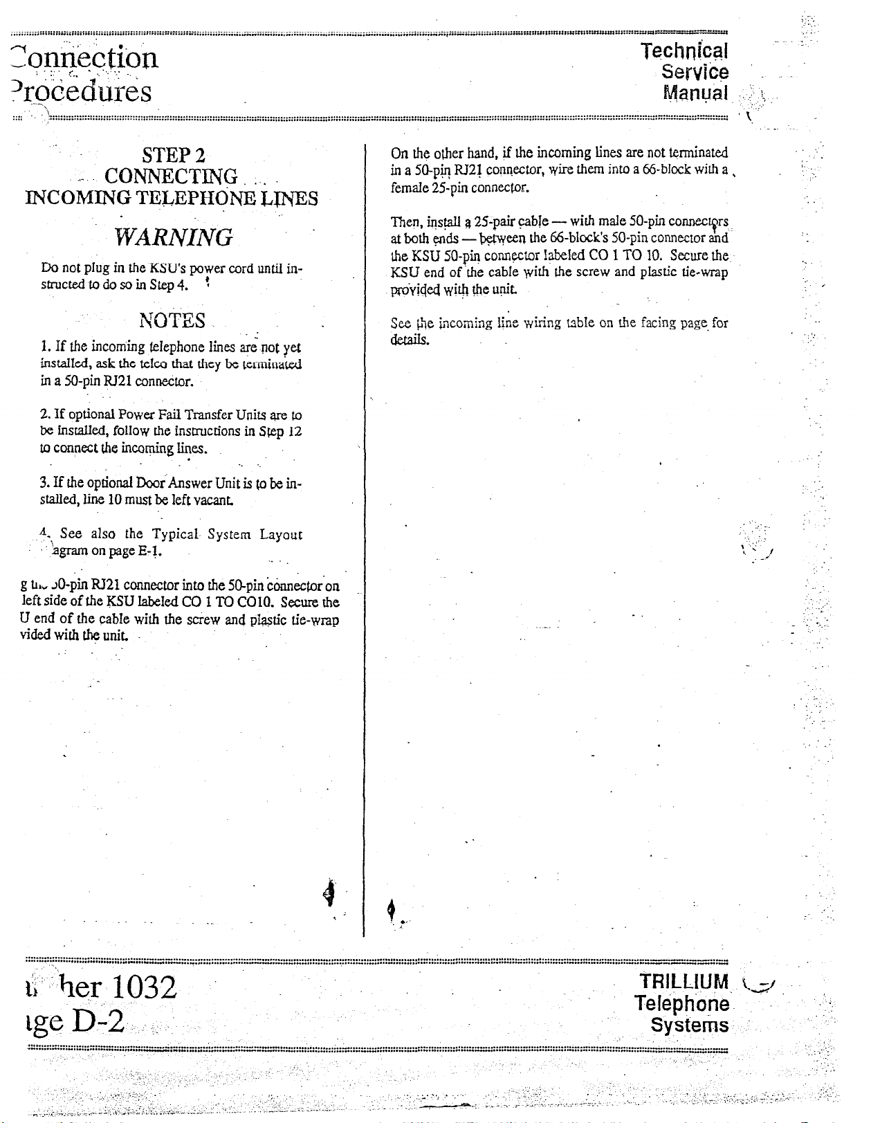
STEP 2
.,-
CONNECTING . . .
INCOMING TELEPHONE IJI’$ES
WARNING ~ .
Do not plug in the.KSU?s power cord until in-
stnlctedto&soinstep4. !
NOTES
1. If the incoming telephone lines a$ not yet
instakd, ask the teIc0 that they be termina&i
in a M-pin RJ21 connector.
2. If optional Power Fail Transfer Units are to
be instaIled, follow the instructions in Step 12
to connect the incoi-@ng lines.
3. If the optional D&Answer Unit is @ be installed, he 10 must be left vacant.
A. See also the Typical- System Layout
: ‘&ram on page E-j.
.
.
._ . .
On the other hand, if tie incoming lines are not terminated
in a SO-p& lU2j conrvxtor, v&-e them into a @-block with a,
female 25pin connector.
Then, iqs@I a 25-pair cable - wiih male 50-pin connecqrs
at both qx3.s - b+syeen she a-block’s 50-pin connector and
Ihe KSU SO-pi17 connqXor IabeIed CO 1 TO 10, Secure the
KSU end of.the cabIe with the screw and plastic tie-wrap
pmiiq4 with th!: u!$.
See @e ycoming I&e wiring able on the facing page, for
details.
:
‘-
. . .
,
:
‘.’
,,
:
:’
g th, JO-pin RI21 connector into the 5O-pin Gnnector‘on
Ieft side of the KSU lab&A CO 1 TO COlO. Secure the
U end of the cabIe with tie screw and p@stic tie-wrap
vided with * unit.
4’
,
, .
fi:-:her
ge D-2.
a* .I... -.--.- . . . . . . -..-1. . . . . . . . . . . . . . . . . . . ..“.-.A -.....-............... . . . ..- -.-. . . ...” ..,.................-................................................................ - . . . . .
. . . . . . . . . ...” . . . . . . . . . . . . ...” ..,....”
,;_ ;, 1,. .,y+ ‘-c-‘,;..,
.,
_.,., I .-.._= :*--.7--I’,
103.2
:,. :
-.“W....L”-.--.-““-...“- . . . . . . ...” . . . . . . . . ...“_..” . . . . . . . . “.....
._-
,_ -.
:
’ _-
.,.‘.“...‘. ..--
,+ ,_ . . . . . . . ;, I:., .;-c- / “. ,__:FC
_- . . .
. .
I
._ .._..-..... z: ..,-.--G-
_. ‘. : .-..
I.,.,
..
. . . . . . . . . . . ...” . . . . . . . . . “...““.“:::::::“:‘:::~::::::::::::E:
. ..., :.>.; . . . . . ,.
‘.
.I.. .:.
. . ..y.
,. ;y;-\;f.. kj.
Systetis ‘,...
/ I.
_ j
.,:
, .,’ .,
’ ., ,;’ . ..’ . ...,__ -‘,;: i. . -:
‘. :--z-z )., .----. --: ,_ .,,... i. .._,_ ~-. .,~.,__.,_.. .-‘T:-- ‘. .... ,:.
r. I r...Ir
.
‘. ‘.‘..
..1..:
_..
)I _
Page 17
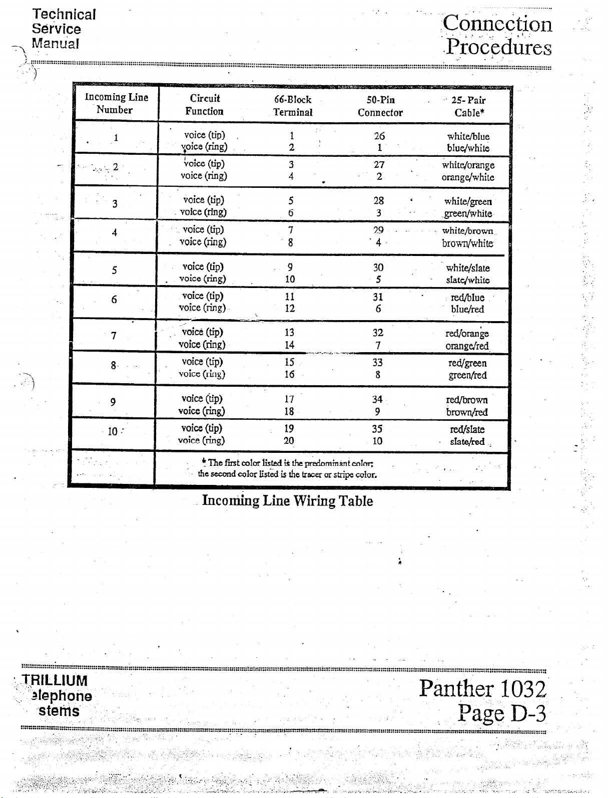
Teqhnical
r...~:onn:~-----;---.“....
S&vice
7 lLymuaf
:
. ..-......-..............................-........................-..-.- ..-... - ..-.....-.........I.............,.....-.....,,.....,.,,...” .,.,.......,...,....,,...........” . . . . . . . . ..(...................... :, . . . . ...” . ...” _..... ,;.*..
.. -- ;
‘:“““““““““....‘...........~...............’............. . . . . * . . . . . . . . . . . . . . ..I... I.. .I...... . . . . . . . . . . . . . .
1’
. . . . . . . . . . . . . . . . . . . . . . . . . . . . . . . . . . . . . . . . . . . . . . . . . . . . . . . . . . . . . . . . . . . . . . . . . . . . . . . . . . . . . . . . . . . . ......................~............ “..l::“:::::::::::::::::
.:
.
-_I
: !
Incoming Line
Number
1
I
Circuit
Function Terminal
66-BIock
SO-Pin
Connector
.’ 25
Cable*
Pair
. .
‘. :
. . .,
.,
hording Line Wiring Table
. . . . . ...” . . . . “.-...“..“.....I”.... --_.^.... L . . . . _
.*-.. . . . . . . . . . . . . . . ...” . . . . . . . . . . . . . . . . . . . . . . . ...” . . . . .._...
1; .?‘,Rf LL1U.M
.,._ .‘tlephofie
.‘ste.jjs
,.:
~*“-“---“...---” . . . . .
. . . . . . . . ..^...I........ . . . . . . . . . . . . . . . . . . . . . . . . . . . . . . . . . . . . . . . . . . . . “...I...
,.
.., ..;:., /~;.-;-“..i; L. I..::. . ..-I’-. ;.. -., . ..(fI.I. ‘..C:;
,- .. ,, .; .-;i; --;-;. -1.: .;‘. ..‘. I. :
..I .‘:-~p,y’;-,‘~., .:...
d , .?‘.:’ ,.
. . ...*
I._.” . . . . . ..-_..__._. “?F
: :., .‘, : ;gr
.
:-- :.,-:.
,~ _ _ .f,‘;; ,. .. “.‘.I :., ... :. :
_,
‘..‘...” .,-
. .-.
,, ;.,.., -- -. .‘.
‘.
. . ..- _T~< .__-.. -
..~-m~~:I:::~::::::~--:n::~.
c..
: . . . . . . . . I . . . . . ...,_ ~ :’ .‘.
‘,;-,‘c - -.
. .,,..y.+‘;, :..-: ._:.-
.
” :-. .
. . . . ._ . . . . . . . . ._. . . . . . . . . . . . . . . . . . . . . . . . . . . . ,
.. Ptinthcl ~uv3s:
Page D-3
. . .
~:l~~~l:~::::::~:~:!:~:.....--..-~ -“--**--*“-- -
. . . . . . . *.**..X!......... * . . . . .
“... . . . . . . . . . . . . . . . . . - . . . . . . . . .
.‘. ‘.
_ :
. .lil
,. :.. ._j_ ..-‘.-
.., -. ,._-...-.
:...
. .. .. .
~:/,.
. .
..L,,~ ,. .-~,,;- -.... :;.7.,.;.-i ,;.... >-:li = ..,. ._ _: .,.., -. -i.r 2.‘. --_. :,: 1. :;..
:.
_. 7:
,:: ..-.._ I -.,.
:
Page 18
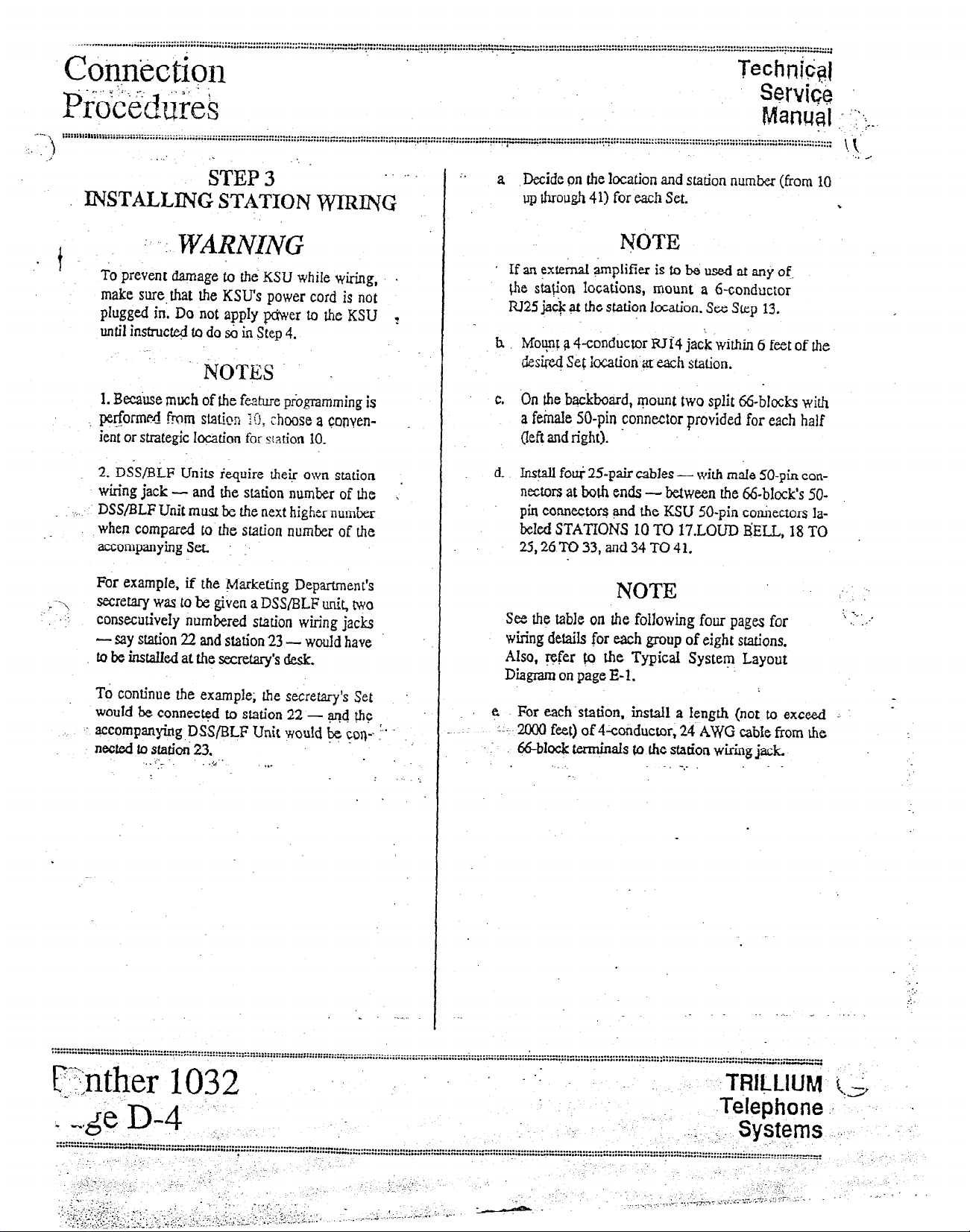
Cotin’ection
::E:::::::::::::::::::::::~:~:::~:::::::::::::::::::~:~:~~~~:~:~~~:::::::::::~~~::::::::::~~~:::::~::~:~::::;::::;;;~:~.~:~.:::~~:;~~~~.:;::::~~
p~6$.cduF;~
.- .--*....e . . . . . . . . . . I” . . . . . . . . . . . . . . . . . . . . . . . . . . . . . . . . . . . . . . . . . . . . . . _ . . . . . . .._........_....
. . . . . . . . . . ..I..........~.... .*.. . .*.e................*............ “” . . . . . . . . . . . . . . ..-....
.i
:. J
2
:
iTEP 3 y
INSTALLlCNG STATION WTRmC
Technk$
Sewi&
Manqal !“,-
::::::::
.
: .
a Decide on the location and station numfzer (from 10
up through 41) for each Set.
., I.-.
1.i’
‘.. .a
%
. 1
I
?C\
.’
:
: .. : WARiV&lJG
To prevent damage to the KSU while wiring,
make sure.that the KSU’s power cord is not
plugged in. Do not apply pciwer to the KSU
until instructed to do So in step 4.
NOTES
1. Be&use much of the fature programming is
I performed -from station :O, choose a copyen-
ient or strategic location for sation 10.
2. DS&BLF Units iequire their own station
wiring jack
DSS/BLF Unit must hz the next higher number
.r
when compared to the station number of the
accompanying Set. :
For example, if the Marketing Department’s
secretary was to be given a DSS/BLF tit, two
consecutively numbered station wiring jacks
- say station 22 and station 23 - would have
to be instaIled at the secretary’s desk.
To continue the example; the secretary’s Set
wouId be connect@ to station 22 - ~4 @s:
accompanying DSS/BLF Unit would pe
netted to sfatiti 23.
- and the station number of the
cop
. .
.I-
.
z
\’
?
.
I . . . . .
VOTE
’ If an external amplifier is to be used at any of.
fhe sh$on locations, mount a 6-conductor
JU25jai$ at the station location. See
h MoFt 9 +conductor RTi4 jack within 6 feet of the
&xi@ Se& iccation a~ each station.
c. On the backboard, mount two split 66-bJocks with
a fetie 50-pin connector provided for each half
(left and right).
d. Inspll foe 25-pair cables - with male 50-pin con-
nectors at both ends - between the &block’s 50pin connectors and the KSU SO-pin connectors labeled STATIONS 10 TO 17.LOUD B’ELL, 18 TO
25,26TO33,and34TO41.
Skp 13.
NOTE i. :
See the table on the following four pages for
wiring detaib for each group of eight stations.
Also, refer & the Typical System Layout
Diagram on page E-l.
5 For each station, instaIl a Iength {not to exceed
L--. 2000 feet) of 4-conductor, 24 AWG cabIe from Ihe
i 66-bIock &qinaIs fo the station wiring j,ack.
_.
-..
1 :.
>
..” . . . . . . . . . . . . . . . . . . . . . . . . . ,.- . . . ...” . . . . . . . . . . . . . . . . - . . . . . . . . . . . . . . . . . . . . . . . . . .
. . . . . . . * . . . . . . ..I. . . . . . “..“..“...“f . . . ..-. . . . . . .
.’
. . . . - . . .
. . . . . . . . ,,.., . . . . . . . . . . . . . . . . .._........... “..” .____.
;;- _‘_, (__, -;.,,- iT ,.,,, l., t.7. --;.: j’. ‘7 1.. --
TRiLLlUbq
-Telephone
.._ ..,
Systems
..-
..- . . . . . . . . . . . . . . . . . . . . . . . . . . . . . .._-.-.
_.
._ -(,,
!. !‘,
Page 19
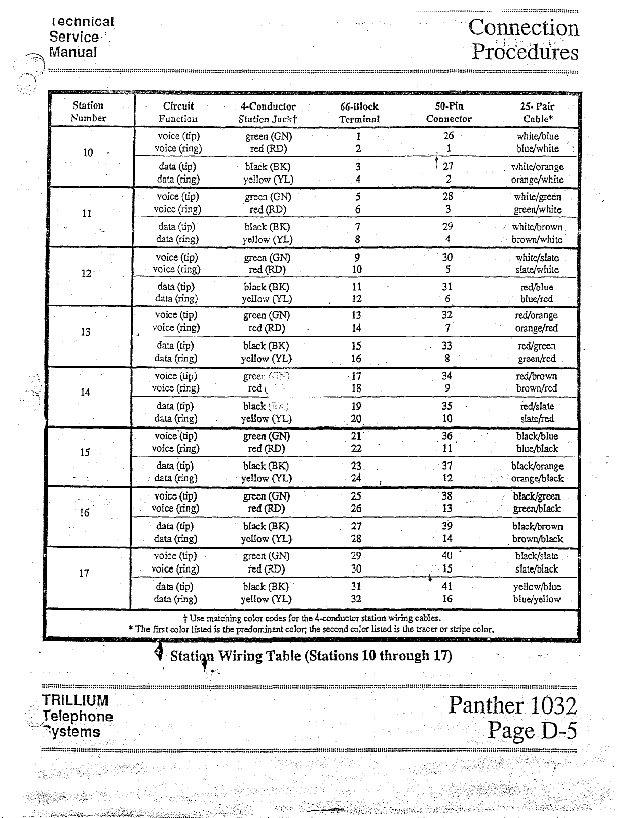
I ethnical
v.I.~.,‘:
Service. :.
13
Circuit 4-Conductor
voice (tip)
voice (ring)
66-Block
50-Pi0 2% Pair
32 red/orange
7 olang+Td
15
. .
16.
17 voice (ring)
* The first color listed is the predominant color: the
<.:.TRILLIUM
: _- T-,I--L--- -
,teiepnone
‘.
‘---
yyst&ms
. .
.-.......I . . . . .-. . . . . . . . . . ..” .._.” . . . . .-................-..--._ . . . ..-.............-..........” . . . . . . . . . . . . . . . . . . . “” . . . . . . . . . . . . . ..“......-I...“........... . . . . . . . . .
. . . . *a.. . . . . . . *... . . . . . . . . . . . . . . . . . . . . . ...” ,....,......._.,-..- -,” . . . . . . . . . . . . . . . . . . . . . . . . . . . . . “.““....._ w....,.. “.‘. . . . . . . . ..I.....+. . . . . . s...““..
. TZ-.’ i/, . . ’ .’ :_
-‘; +‘.+‘..-:.:. .- ;.., I
:. : -..:,._ :::... . ...‘.:. :.‘-.i I i.’
?,.:+.;,.-: ;. ‘~:F‘~~i;:~~~~.i-~.:‘,.~,. :+..ky/.ri..i,. .‘--:‘:rlr” 7.” .^.. “. .
. . . . . . . .,,, \’ i,.l.o_.
,.
..‘,
data(ri.ng)
voice‘itip)
voice (ring)
data&) black (EIBK) 23. .37 black/orange
d-e@)
: voice (tip)
voice (ring)
data {tip)
~Q(kd.
voice (tip)
data (tip)
data 0-h)
$ Use matching color c&s
8 StatirQn Wiring Table (Stations
,
l -;
Ye~owcIL)
green (GN)
red OW
yellow (YL)
green WI
=d(RD)
black (BQ 27
yellow (Yi)
green WI
tied (RD)
bIack (BQ-
yellow (YL)
for the 4-cnnductor station wiring cath.
3?
21’
22‘
ti , 12 _ :: -. orange/black
25 .
26 13 :’ p&black
23
29.
30
31
32
second c&r listed is the racer or shipe
10
through 17)
10 slate/red
.36.
11 blue/black
38 _ ,_ bWdgreen
39
14
40 -
15 slWblack
,
41 yellow/blue
16 blue/yelIow
cdor.
black/brown
. bro+n/black
+ _.
Panther 1032
.P& D-5.
. . “...I . . . . . . . . U...“.” . . . . . . . . . . . . . . . . . . “i.. . . . . . . . . . “-“*-....-..“..
. . . . . . . * ,... a* . . . . . . * . . . . *,* ..,.,. * . . . . . . *..*.... .,.... . . . . . . . . . . . . . ...“........“.” . . . . . . . . . . .
,.‘.. :
:._. ,-
1 ,,
. .: :..
.
. .-.
~‘ir2.~;.“:..I, -:.
-.
:
.’ ,;:
.“_. . . .
.‘,., ‘.‘-.
:‘ ;., ._ :;.
.- ‘,.I’ ;: .i ..’ -. _: ,
- ., ,, ;A.+~~; .‘> ,;; :l’:x.; ,,: :&*F :-:.;:: i&:y%.:i:>~::.. 1 . . .-,
. . . . . ‘-:
:
.,. ‘_,-‘._
,,. :-. ‘,-
-‘_ ..._
-, ) -- . . / ‘; . ..^ .-;;-. ..,. ii’. ;.-
1.::
i. :..:-
: ,k-.- - ,- ‘..
bhMIue ._..
bhzk/slate
-
._ ;
‘_
(_
‘.
. .
. ..-
_~.. ,’ .’
-_ _ :.., +: : y;; ‘:‘, -7 .’ ;
.
--, :,\, ^i
r
Page 20
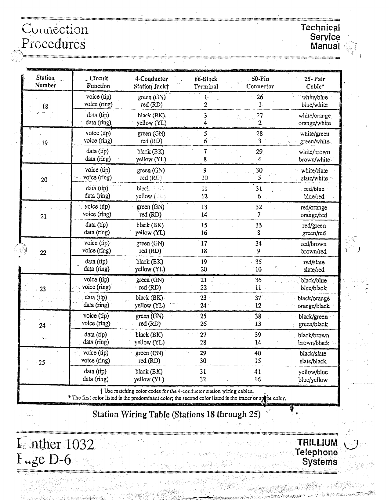
” . . . . . . . . . . . . . . . . . . . . --..._-...- . . . . . . . . . . . . . . . . . . . . . . . . . . . . . . . . . . . . . . . . . . . . . . . . . . . . . .
- . . . . . . . . . . ...” . . . . . . . . ..“...............I . . . . . . . . . . . . . . . . . . . . . . . . . . . . . . ..*...... *..“...:::::::::::::::::::::::y.~~;;:q::;:....” . . . . . . . . . . . . . . ...-.” . . . . . . . . . . . . . . . . . ...” . . . . . . . . . . . . .
r(
.: .
+Amctmn
. . . . . . . . . . . . . . . . . .._........_............._.....__.........~............ -_ . . . . . _ . . . . . . . . . . . , . . . . . . . . . . . . _...I..._ . . . . _“.,._,“..”
. . . ..-..................... . . . . . . . . . . . . . . . . . ..C.-.“.“...-.-
Technic+
Service 1.1
Pmiedkei
,--?l
. . .
::::::::::::::::::::::::::::“i::::::::::::::::::::::::::::::::::::~.:::::::;~.:::::::::::::: ::::::::::: yya:: *::: :: :::::::; ;: ;::::; :::::::;:; ::;::: ::;:y::::::::; :::::::::::.:;:: ;; ::::: :: ::::,...............:::: :::: :::::::::::; :::::: z :::: ;= ::::;::: :::; ::::::: :;::::: ::
,.. .I
, I
. . . . . . . . . . . . . . . .
Manual :I: _;
’ I
-..-a-.* . . . . . *-..--..- . . . . . . . . . . . ...” . . . . I...” . . . . . . . . . . . . . . . .._............................................................. ^ . . . . . . . . . . . . . . . . . ..-............... i.; . . . . . . . . . . . . . . . . . . . . . . . . . . . . . . . . . . . . . . . . . . . . . . . . . . . . . . . . . . . . . . . . . . .
-*....*.* . . . . . . . . . . . . . . . . . . . . . . .
_-,.
I-::;nt,her
. . . . . . . . . . . . ...” . . . . . . . . . . ...” . . . . . . ...” . . . . . . . . . . . . . . . . . . . . . . . . . . . . . . . . . . . . . . . . . . . . . _ .,................,............ . . . . . . . . . . . . . . . . . . . . . . . .I... . . . . . ......... .......,..,*...,* .... .......... ..... *:r _..W 1....1..“__
‘1032
’
. . . . ..... _I..” ...--. _._
TRILLIUM u
I’
Eage D-6. -: : -‘, .’ .T$?$;;;. ‘. “,.
.’
.-....- . . ..I. *.- . . . . . . . . . . . . . . . . . . . . . . . . - . . ..-.....-.......................................................... : . . . . . . . . . . . ..-........................ . . . . . . . . . . G . . . . . . . . . . . . . . . . . . . . . . . . . . . . . . . . . . . . . . . . . ..I . . . . . . . . . . . . . ..I................... I.” . . . . . ..-...-.. I..”
.z..- . . . . ...” . . . . . . . . . . . . . . . . . . . . . . . . . . . . . . . . . . . . . . . . . . . . . . . . . . . . . . . . . . . . . . . . . . . . . . . ..-...................................................... ~ . . . . . . . . . . . . . . . . . . . . . . I . . . . . . . . _..I . . ...” . . . . . .
. ..I . . . . . . . . . . . . . . . . . e..... . . . . . . . . . . . - . . .._._ ““” .-__
Page 21
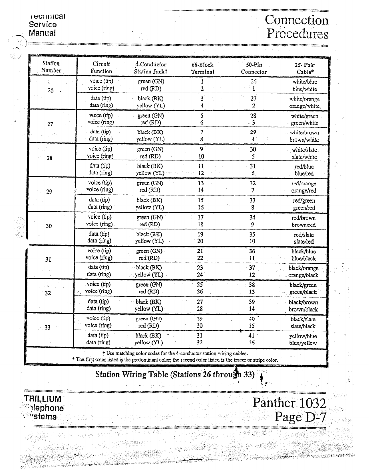
I tmir1Ical
:::::::::::::::::::::::::::::::::::::I:::~:::::~:::::~::::::::.~~.~::::::::::::::::::::::::::::::::::::::::.~:::~:::::::::::::::::::::~::::~::~:::::::~:
Service
-~ Manual
‘.. .\
i
i .-....... * . . . . . ..- . . . . . . . . . . . . . . . . . . . . . . . . . . . . . . . . . . . . . . . . . . . . . . . . . . . . . . . . . . . . . . . . . . . . . . . . . . . . . . . . . . . . . . . . . . . . .
. . . . . . . I.. . . ..“........................................ . . . . . . . . . . . . . . . . . . . . . . . . . . . . . . . . . . . . . . . . . . . . . . . . . . . . . . . .
’ :
. .
..__.__........... . . . . . . . . . . . . . . . . . . . . . . . . . . . . . . . . . _ . . . . . . . . . . . . . . . . . ..,....., I.. ..,. . I.... . ...1...1. . . . . . . . . . . . . . . . . . . . . . . . . . . . . . . ~ . . . . . . . . . . . . . .
..__._....,.._._.I..~....................,................,..................... -...- . . . . . . . . . . . . . . . . . . .._
Connection
&r&edtiies
station
Number
26 .
27
29
Circuit ji-CondLictor
Function
voice (tip)
voice (ring)
data WP)
dala(iing)
voice (tip)
voice (ring)
data w
cl- @hi9
voice (tip)
voice (ring)
hfa @PI
~Q(az>
voice (tip)
voice (ring)
data (GP>
data (ring)
voice (tip)
voice (ring)
da 03
&a 6-w
voice (tip)
voice (ring)
cl&a WP)
de3 6%)
voice (tip)
voice (ring)
dafa w
data km)
voice (tip)
voice (ring)
dafa(tip) black(W) 31
data (ring) yefIow (YL)
t Use matching color cedes for the dconductor station wiring
Station Jackt Terminal
green W-0
red F-W
black(X) 3
yellow (YL)
@en (W
n-d WI
black (BK) 7
yellow (YLJ 8
green (WI
d(RD)
black (BK) 11
yellow(YL) .:,. . .I2
ti=n (WI
red (RD)
black (BK)
YeUow OW
green @N)
red W>
black (EX) 19
yellow (YIJ 20
green (GN).
red WI
.black@K)
yeUo* (YL) ii
green 0%’
r=i(RD)
black (BK) 27
yellow (YL)
green (0
red 0)
66-Block
A25 .38 black&rem
.a
SO-Pin
Connecfor Cable*
1
2
4
5 28 white/green
6
9 30 white/slate
10
13
14 7 orange/red
l5
16 .
17
18
21 ‘- 36 black/bIue
22 11 blue/black
26
29 40 - . . blid/slaie
3.0
32
cables.
26 white/bIue
1
27
2
-3
29- white/brown
4
5 slatdwhite
31
6.
32
33
8
34
9 brown/red
35
10
37 black/orange
12
13
39 bfadqbrown
14
15 s?afeIbIack
* 41’
16 bIue/yelIow
25- Pair
blu$dGte
‘white/orange.
orange/white
green/white
bruwn/white
red&he
blue,‘red
rd./orange
mVgreen
greenired
red/brown
ld/Shte
SIate/ted
orqngq’black
.- green/black’
. brown/black
yellow/blue
. . -
I
-
?
Station Wiring TabIe (Stations’26 throt& 33). i’
. . . . . . . . . . . . . . , .
..* . . ..I.......... ::::::::::::.1::::::::::::=::::~~.:::::::::.~::~~.::~~~.~~~~~~.~.~~~~~.:~.:~.~~~:~:~~~~~~~~~~:~:~:::::::~::~~:~::::~~:~::~:~~~~::~::~~~~~::~:::~:~::::::~:::::::::~::::::::::
~~.TRflJAJM
..L -TY.,lephone
Panthe
_.
Page 22
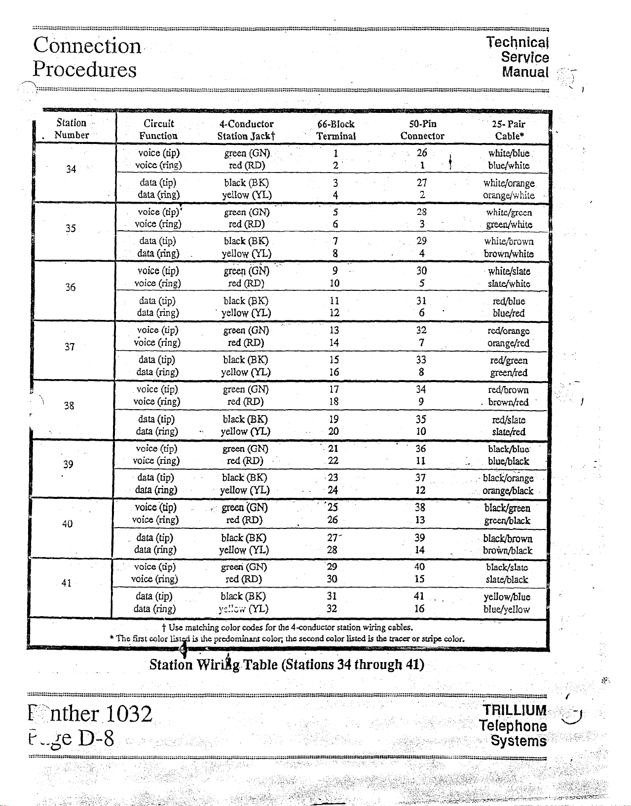
Chme&on~
.-~*i&~;~.~f;z.~
,:;:~,~~,~,~-~s~,~;r~~.-~~~~~~-~-~.~.~~~~”
Procedures
‘1.. . . . . . . . . .
liXtpliC8~
Service
Manual 1:; 7
’ I
‘39
40
41
Circuit Wonductor 66-BIock
Function
voice (tip)
voice (ring)
data @P)
data mwi9
voice (tip)’
voice (ring)
data (tip)
data(ring)
voice (tip) griiq (i3-q -”
voice (ring)
data (GP)
data w-%)
voice (tip) green (GN) .’ ‘. 13 32
v&x (ring)
aa @PI
data b-&T)
voice (tip)
voice (ring)
data (ring) -<
I
voice (tip) greert(GN) ‘~21 -‘36 bIac&blue.
voice (ring) -rcd(RD) ... 22 11 :. blue/black
data (tip) black (BK)
&Jfa m-49
voice’(tip) _ green (GN) :‘25 -. 38 ’ black/green
I’
voice (ring) =doiD) 26
data @PI
data 6-b) yellow CfJ4 28
voice
(tip) greeri (0
voice (ring) rd(RD)
ha (U’P).
Station Jackt
@een (GN). ‘.
red CRD)
black (BK) 3
yeIIow (Y-L)
grc-cn(GN)~’ ” ‘5
reMW
black (BK) 7
Mow WI
red P-W
black @IQ 11 31 red/blue
yellow 02)
red CW
black (BK)
yellow (YL) 16
green WI
red WI
black (BK) 19 35
yelIow (YL) .. 20 IO
,yeIIow(YLJ .. 24 12 orange/black
bIack (BK)
black (EN)
Terminal
1 26 whiti$Aue
2’ 1
4
6 3 .
8 4 brown/white
9 ‘:
10
12 6 * bIu&d
14
15 33
17 34
18 9 . brown/red
.23
.
27’ 39
‘29 40
30 15 slate/black
31 41
32
SO-Pin 25 Pair
Connector
,t
27
2
28 white/green
29
30 white/slate
5
7 :
8
37
13
14
16 blue/yellow
_
. . yellow/blue
white/omnge
orangdwhite
green/white
white/brown
red/orange
orange/red
- bIack!/o&ge
gxen/ilack
bIs.ck/bsown
bro+m/bIack
black/slate
Cable*
blue/white
slate/white
Wg=n
Peed
red/brown
SWd
. :
I
. .
I
: _
t Use matching color codes for the 4conductor station wiring
the
* The first color listql is Ihe
.
..****..--...- . . . . . .- . . . . . . . . . . . . . . . . . . . . . . . . . . . . . . . . . . . . . . . . . . . . . . . . . . . . . . . . . . . . . . . . . . . . . ..-......-.......-...-...... . . . . . . . . . . . . . - . . . . . ..- . . . . . . . . . . .
. .._....I......“..“..“.”
FY”nther
. . . . . . . . . . *...a . . . . . . “...“...” . . . . . . . . . . . . . . . . . . . . “” . . . . . . ...” ,..*..*....... *........-.. .-..... “““......,,....a.....“...” . . . . . . . “...“..~~:::::::;::::::::::::=:::~~:~-~:~::::::::::::::~~~:~~~~
I()32
Statidn WiriBgTabIe
iQe p-8 I :
:::::::::::::::::::::::::::::::::::::::::~~:~:~~::~:::~::~~ :::::::::” ,::: “;.s :::: “:= :::: =;: :::: z”::r,.” :::;::::::: :““:::::::::*1”“‘...... . . . . . . . . . . . . . . . ...-“..” . . . . . . ..I......................
: ;;
;, .,, .,_ . .
: ; / :;i:: ‘,:.,‘. ‘, .,y:.,.: :,; _,.. .- .:.-: .-, :. ‘. :;; . ,,
-& ,,., ,.,,,,.---l~~,,.:;.mr.~-;--r P..I i.. “‘.I~‘...---
‘_
, i .‘.
.+:;.: ., :-
,
,; _.-.- ;. ..
.-;- ,,.: ~:.,. ._.’
,,* -: .,+.- 1 1. r
__ _ ._.. *,,d,...
-,;. :.:g+...
predominant color;
. .
.’
:.
. .
‘.
‘. ‘.
:;.;: ,+.;;:yc>.: __ ;,. ;., “., ..-‘:;
,“., ,i . . . . .
.I
, _ . . . --1 -.
second color listed is the tracer
(Stations 34 through 41)
. . . . ..I..............
. . . . .
,, ._
: ,-,
..,-r .,> -,~: ,,. ),. ;.-
- .:. ,;:,;:.: : ::-,y::I:j-’
..,,, .:. i !. ‘.
..’ .I. -
..“..,.. . . . . . --“.“-.~.-“....“...“,...“~..” . . . . . . . . . . . . . . . . . . . . “.I_.
-’
I_
: r .:.;;;; ,, y-.:. _. .s,. :,
.L.. ..,
_:,_ :
cables.
or stripe color.
:
-_
; .-. .;
,,... .’
. ,~. ; i .. 1: -. .,:: ,.‘ --i: =-,;
:
r,&&y,r;+;.-c’
;,, c‘ .L_ .; ,-I. ;‘. y: ,. .:., i;
.: Telephone
,I
. . a... . . . . . . . . . . . . . . . . . .
“I
:_ .: ;,:..p (. ,, T. :, :‘::,‘ :’ i,
._ .i ;‘.-. .., .’
.
iFjll&lUM-:. .& ,.-
I qstem,g. ;;,+ ,.
.:
:,_
: ,_
.! ,.. .:>. (.
:
.:
;-,7’.b, ‘,_‘-
:-:.
:
‘. ,, ,:“._ ; -.
? ,.::>:- ,, .).‘. i . .
2; .,:_ -,- :. .- i,‘.;
- _ .z”-’
., 4 7 ‘I
Page 23
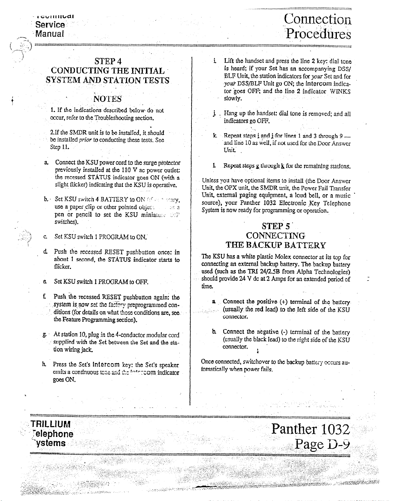
/ (:..
-:.;:j
\
..‘-‘--\.-
!
,
--v-v-
“-.-.““....““...-“1 I............ * I..... - . . . . . - . . . . . . . I . . . . . . . . . . . . . . . . . . . . . ..-........-........’ . . ...” . . . . . . . . . . . . . . . . . . . . . . ..“......-...... _I . . . . . ..-......................... . . . . . . . . ..-..............-. * . . . . . . . . . . . . . . ..-. I”..” .,-.....................”
j
. . . . . . . . . . ..I... - . . . . . . . . . I . . . . . . . . . . . . . . *.*...-..* . . . . . . . . . ...” . . . . . . . . . . . . . . . . . . . . . . , . . . . , . . . . . . . . . . . . . . . . . . . . . . . . . . . . . ...*. ,...... ~ . . . . “,......_U . . . . . . . . . . . . . . . . . . . . .,,..... .I.... . . . . , . . . . . ..............................” .................,....................,..-
.
STEP 4
CONDUCTING THE INITIAL
SYSTEM AND STATION TESTS
‘.
~i\lo~ES
1. If the indications described below- do not
occur, refw to the Troubleshooting section.
23 the Sh4DR unit is to be insta.lIed, it should
be installed p&t to conducting these tests. See
step 11.
i Lift the handset and press the line 2 key: dial tone
is heard; if your Set has an accompanying DSS/
BLF Unit, the station indicators for yaw Set and for
yolci DSS/BLF Unit go ON; the tntercom indica-
tor ‘goes OFF; and the line 2 indicator
slowly.
j. . Himg up the handset: dial tone is removed; and all
indicators go OFF.
\
k Repeat steps i and j-for lines 1 and 3 through 9 -
‘and line i0 as tiei& if not used for the Door Answer
Unit’ _
tireis
WINKS
I
_.
....,
,:.
.;. j
I
a Connect the KSU power cord to the surge piotector
previousfy instaIled at the 110 V ac power outlet:
ihe recessed STATUS indicator goes ON (with a
slight flicker) indicating that the KSU is operative.
b.. Set KSU smirch 4 BATIZRY to Oh! ::r
use a paper Clip or other pointed objz . :’ <$
pen or pencil to set the KSU miniatc:;. .:::‘
switches).
‘.
c Set KSU switch I PROGRAM to ON.’
d Push the recessed RESET pushbutton once: in
about 1 second, the STATUS indicator starts to
flicker.
e Set KSU switch 1 PROGRAM to OFF.
f. Push She recessed RESET pushbutton again; the
.sysfem is..qow set the f&-y preprogrammed con-
’ ditions (for detaiIs on what &ose conditions are, see
the Feature Programming section).
g At station 10, plug in the 4-conductor modular cord
supplied with the Set between the Set and the sfatiorl wiring jack
I .,‘~~y,
1. Repeat steps g. through k for the remaining stations.
UnIess you have opfionaf items to instal.I (tie Door Answer
Unit, the OPX unit, tie ShlDR unit, the Power Fail Transfer
Unit, external paging equipment, a loud bell, or a music *
source), your Panther 1032 Electronic ,Key Telephone
System is now ready for programmipg or operation.
STEP. 5.
COIVBECTING
TliDI BACKUP BATTERY
The KSU has a white plastic Molex connector at its top for
connecting an external backup battery. The backup battery
used (such as the TRl24,QSB from Alpha Technologies)
should provide 24 V dc at 2 Amps for an extended period of
firm.
a Connect the positive (i) terminal of the battery
: ;; ..
(usually the. red lead) to- the left side of the KSU
COMeCtor.
h Connect the negative (-) termin of the battery
(usualy the black lead) to the right side of tie KSU
coMector. .
;
h Press the Set’s Intercom
emits a continuous
goes
ON.
\
tGne ~56 L!x fnf
key: the
. . .:TRILWM -.
:_ .
‘.
Mizphone
hystems .’ ::.-:
--.--.r-...--.-..-.“~-“.-...“...-.”~”-----” . ...”
--“--.“.-..-“-...“......“...“... . . . . . . v . . . . . . . . . . . . . --.....- . . . ...”
,’
;-
.,,, j; >.~“, , : ,,* ..,
I.
,..
:- :_,. :...’ :,.-
_i ,I-:.;.;:.$.: ::.; ..i
_ _-:_ .,;.,.r:.‘..‘.
F..:>...
I-;; :c.;L;..p,jr .~ ;>. :: ;:,;,.. ( : _.
..,--i:-<-?-., ,-. 7:<-: i “.,.~ ,....: I::- .:: I
.,A ,,,.
.-. .::. ,..,I’
.I
’ _’
.:, -:- . . . : *
,,;. :-..
_, r.,. ‘...., ;,’ ,i’,q. ,,:I. :,.:
~- .‘-.:‘.:~~.,.;...;.‘;“
.‘_ -‘z’-r ,.,,r;‘,s: i -
I : ,_,,, :;:s.-‘... .
..‘-. :.
,~,..--:~-..r~. ‘.
,I, : .’
: ,~C :;
-1 -. <.. \ i ,.
-i, ;
Sk’s speaker
pxorn
. : .._ -
indicator
,..
._.
: I
:
:,: ;,.:
. . -_ .-
Once connected,
fomaridy when power fails.
switchover to the backup batteri occurs au-
.
_ .: .^ ,:... .._
Page 24
. . . . . . . . . . ..*.........-~..........-.---~-.......~........-..--........-
i”....“““..........~..“.~...-.-“~....”...*....,..........~.,........~*......,.~,~~,*~~~,,~~~,~*,~~~~~~,,,,,,~~~~~~“~~,,,,“,~~~“~~,~~~.~~..~...~........,............~.~...-........~
~.“.~..,,..-‘...Y~..‘-~.r.....~.m.........................,**.,...__.......~::::::::::
. . . . . . . . . ...“.” -.,. - -...- -L”l-n..~~
f+-&~n&$j~
~p&&.j&
,.-..,
. . . . . . . . . . . . . . . . . . . . . . . . ..*..C...-“............................
:. ,.
: ;.’
D,oor
.
Answer
. .
Unit Ir&allation
.-...-....“,.......L............
“....“...“.“.........“.W”....+
. . . . . ..~............................-......-..................*....-..........
. . . . . . . ..f.*...“r-“...........*.........l
..~....r.r..u..~.~-..*~~--
‘, .
_~.-...n.....r.....................................~....~....... .
~..“...“~.“-“~“.-‘““..-~1.----....*”*r..”.~...., -.-. _._
-
. . .._I...-.....“.-..........*
-ralrricgl~ ‘.
%-Vice ‘.
Manual : Y:’ .I;.:
,...
:
&or Module
8 ’ Rqoye t)e’s+rew sec&ng the Door Modules’ %
:
.
front coy&, grid separate the front from the back.
%
;
Im.a3ti0~
-..........,Y.*.......,.......................L
6 Mount the backs of fhe &x Modules at the de-
sired entryway lOcations, using the two mounting
screws #knished w’ith each Door Module.
c. Run a. fengtb (not to exceed 2000 fet) of 2-
cmdpztor, 24 .AWG wire from the Door
.
,’ -_, ,
:
Unit to each Door Module.
.
Answer
-,
<.‘. jl..
1
I
._.-
/
a Mount the D&r Answer Unit on .the’backboard
along with the KSTJ, using the four screws supplied
with the equipment
b. Connect a 6xo@1ctor mod&cord (not supplied)
tr? the connector la&kd DOOR on the EXJ and the
connector labekd
DA on the i>uoi Arrswer Unit;
d _ Fe& the wire through the hole in the base of the
.’
back of me Door Module,
e:
Strip the cable e?cJ arid secure it to the screw terrni-
,.; .. II& found on the backside of the Door Module’s
front assembiy.
I
I’. Replace the &or Module’s coverpd tighten the
.saew to secure the front to the back.
g. At the Door Answering Unit, strip the cable ends
and secure rhe cable from Door Module 1 fo the
screw termin& labeled Dl and the cable from
.!
Door Mod+e 2 to tkscrew terminals W&d D2.
.
.
-_
......
..-.-.....-.-“..l.................~.-~ .,
-......“..-.n..h..s.-....
-;;;.:ihth-er
.....
--~~~“-.--I~...-...~....L-..W.~..”.....~.......“..............~~......-~.....“.............~..1.........................“.......~ -.-........--.......................~.-...-.........................- .........
.1032
................... ..--...-.................................
..
... -:
',
:
...
.................
I..
............... . _.._
.“............“.........,...“,,~=::^ =
.........
*_
~Rf~LIUM.\~ -1
Page 25
1 echrnical
....,,,*,,.._.....*.,,.
.y:.,y..
Service
c ‘... Mahal
,-;y _
;:~::::y...-.....-...... . . . . . . . . . . _ . . . . . . . . . . . . . . I . . . . . . . . . . . . . . . . . . . . . .
. . . . . . . . . . . a.. . . . . . . . . . . . . . . . . . . . . . ..a... . . . . . . . . . . . . . . . . . . . . . . . . . . . . ..I . . . . . . . . . . . . . . . . . . . * . . . . . . . . . . . . . . . ..-...........................-............ ~ . . . . . . . . . . . . . . . . . . . . . . . . . . . . . . . . . ........................
..__................................... ^ . . . . . . . . . . . . . . . . . . . . . . . . . . . . . . . . . . . . . . . . . . . . . . . . . . . . . . . . . . . . . . . . . . . . . . . . . . . . . . . . . . . . . . . . . . . . . . . . . . . . . . . . . ,. . . . . . . . . . . . . . . . . I
.: ,_
. . . ..-.. -I . . . . .
) .;’ :.;:
. . . . . . I . . ..-....... l...l..“.-.- .-....... I.-- . . . . . . . . . . . . . . . . . - . . . . ..I...^ . . . . . . . - . . . . . . . .._.._
COnnectiQn
I Procedii&
. . . . . . . . . . . . . . . . . . - . . . . . . . . . . . . . ..-...*.i . . . . . . . . - ._.....” . . . . _ . .._......_....” . . ..-..........--........... - . . . . . I . . . . -..” . . . . . . . . . . . . . . . . . . - . . . . . . . . . . . . ..-.
. . . . . . . . . . . . . . . . . . . . . . . . . . *...* . . . . . . ...* . . . . . . . . ...”
. . . . . -- . . . . . . . . . ...”
Door Answer Unit Test
If the indications deskbed below do not
occur;refer LO the Troubfeshooting section.
a. Door Module l-initiated catling:
i At Door ModuIe l’s enfqway, have someone
press tbe.dFr button: four groups of 4 short
tones are heard it ail Sets programmed to ring
on line 10; and the line 10 indicator F?LAS%ES
slowly.
ii. At any Set, pick up the handset and press the
line IO key: the line IO indicator WINKS; if
yours is a BLF Set, your station indicator goes
ON; ind you and the person at the entryway
are ccnlrlected.
iii At the Set, hang up the handset: all indiktors
go OFF, and the calI is terminated. .
,:
.--y..,.
..j
.I.
. .
b. Set-initiated calling:
Set-initiated door module intercom calls can
only be placed
Module 2.
NOTE
.
NOTE
to
Door Module 1, not to Door
c. Ekxr Module Z-initiated calling:
i At Door Module 2’s entryway, have someone’
press the door button: four groups of 2 long
tones an? heard at all Sets pmgrammed to ring
i
on line 10; and,the Iirle 10 indicator FL.ASHES
slowly.
ii At any Set, pick up the handset and press the
iind 10 key: the line IO indicator WWS; if
yours is a BLF‘W, you station indicator goes
ON; and you and the person at the entryway
are connected.
iii At the Set, hang up the handset: sll indicators
go OFF, and the call is terminated.
i AItemativeIy, at any Set, pick up the handset
and press the line IO key: the line 10 indicator
WIJQCS; if yours is a BLP Set., jwzu station indicator goes ON; and the person at Doui
Module 1 hears a burst of ringing,
ii. At the entry way where Door ?&dul& 1
stalled, the person responds by speaking in the
direction of the moor Module: you and the per-
son at the entryway are connected.
iii. At the Set., hang up the hanGet: all indicators
go OFF; and the call is terminated.
\
Q
*’
. .
. .
.- . . . . - . . . . . ...” . . . . . . . . . . . . I..._ ._^. - . . .._......” . . . . . . . . “._“U.__._” .-...,-... rr’-r .--,.-I-.-.-.- “_
. . . . . . -.* . . . . . . . . . . . . . . . * . . . . . . . . . . .
_
:.:-,TRILLlUM ‘.
. . . . . . . . ..I. I._ .._...I.” . . ...” . . ..I.... I . . . . . . . _ . . . . . . . . . . . . . “I . ..C. _-“” .,..,.” .-.....--- --==n.., . . . . . . . . . . . . ..._..” . . . . . . . . ““..” .._,._...,....,. “.
‘.- .-$el@phone
Systems
“-.“-.----.--....” . . ..I --.r-r-G...... -...-- “.._ -... &-,..“.A ..-._*____ &,.,,,,,
‘......‘_.-.....-..“.........“...-..- . . . . ““.*-‘*‘*‘“......L”..“~.“.......”...”.””....*..~.~~~ .__C. . . . ..“..!-“““m” . . . . . . . . ..-......_. “: . ..-. “~_ _.._.._.,..... ~ . . . . . L . . . ...”
_.
: c~ ,,; -.; .C:^‘._ .,.
. : “.
” .__( :.. .:
.(.. .,::i.-. .;..+- _ .: I
. .. ,,
;:I... ,‘+ z~ ;.,, ,, :~-:-~.~i:~~Lf,-:~.,;,:;~,:~;, y, _ -::.- , -- Ti;-lT--=,~:.%-- ;.- -:-
.“:.::;=,“-y;:>& ,.-* p).:‘.“, .,.:.:, f:/:
,,!. F> ./ >A-
/,
. . . _, ,I. .,.,,. ~
., :.:. >... .:; .,:.,.T
,,, _ -,,: ,_.. i .,.. ;: r”“.:, 5’
., ., I
-.I ,..., .:“..>: :~~;r. ;
:
_:: .: ‘:
j:,.., ‘...?, .‘. :
7 ,;.:
..:-: :A.‘:,
_:
_
iS
in-
C<..Y
-“:; .:
.,..I ; ,;,
.“...I . . . . . . . . . . . .
. . . . . . . . . . L.......“..+.....“..- -.-.-” -.......,...,...._..., _...*.-
., - I . .
.- .,,, ‘, .- .,.’
.,.
*. _. ._: .,..... fll..,:; :.y. -I ,,,. .li .I
.
:.
;
.,*..e . . . . . *.- . . . . . . . . . . . . . . . ...” . . . . . L
n-i-~mlm.er~1032.:
Page D-11.
-..._ “-,,.-,*,,..*
-,:;-,-y.r;;,‘~ . , ,;,:;-. . i: .: (
:
“,)” “.“U”..... . . . . . . . . ..-..“.“I......- ---__
_.. ^_ _._ r . -., r
..
-.Tr--
_
Page 26
. . . . . . _ . .
...” . . . . . -....
. . . . .
-.1_-_.-...-
. . . . . . . . . . ..___.
. . . . . . . . . . . . . . . . . . . . . . . . . . . . ‘ . . . . . . . . . . . .
:......,..I
,,,.”
.,...-...
(.?‘.“.,..,
. . . . . . . . . . -.....
_ . . . . . . . .
..~
.-.-----------------
.~..
CO1
,.nhx[ion
p~?~-~ti*&s
.--.-\
,::. s . . . . . . . . . . . . . . . . . . . . . . . . . . . . . . . . . . . . * . ...” . . . . . . . . . . . . . . . . . . . . . . . . . . . . . ...” . . . . . . . . . . . . . . . . . .._........-........-............................. : . . .._............................................. . . . . . . . . . . . . -.-...- . . . . . - . . . . . . . . . . . . . . . . . . . -..- . . . . ........
. . . . . . . . . . . . . . . . . . . . . . . . . . . . . . . . . . . ...” . . . . . . . . . . . . . . . . . . . . . . . . . . . . . . . . . . . . . . . . . . . . . . ...” . . . . . . . ...” . . . . . . . . . . . . . . . . . . . . . . . . . . . . . . . . . . ..-.......................................... I._...“.... . .... -.- .......... * .......... -..e-..--...-...- ....I .....
1
STEP 7 .:.
CONNECTJNG THE MUSIC SOURCE
34Usic Connection
a Connect one end of the cable (not’supplied) into the
music source’s output jack
‘.
c
Testing
i.
the background music on hold:
Hqve someOne G$I in on outside line 1 (alter-
,patiyely, you can call line 1 from line 2):
ringing is heard at all stations programmed to
ring on line 1; and the line 1 indicator
FLASHES slowly.
-j-$xg-hi
S&-vice
Mam.lal ;;;,g~.;
. .
!‘,<’
i
1
l
,,.I.
. :
:
.-
:
.’
,I;.:
:. . .-’ :. ,
:- _,
-:
:: _.
:
: .,:‘.
. h Connect the other end, w@ch terminates in a 1/8-
inch mini-jack (phono, not ste&q or attenuator),
into the KSU connector labeled h4XJSIC. ,
.Vusic Test .
NbTE
If thk indications described below do not
occur, refer to the Troubleshooting section.
a Turning background music on at a Seo
i At any station, with the handset in its cradle;
press the
cator WINKS slowiy; and a continuous tone is
‘-/
heard over the Set’s speaker.
ii. With the handset still in its cradIe, dial *
intercom Key: the intercom
intercom
uous tone is replaced by background pusic
coming from the Set’s speaker.
iii. At the music source, adjust. the level of the
background music for the desired Ioudness.
b. Turning background music off at a Set:
i At any station, with the handset in its cradle
press the
cator WINKS slowfy; and a continuous tone is
heard over the Set’s spiker.
ii. With the handset still in its cradle, dial * 4: the
Intercom Key: the Intercom indi-
Intercom
continuous tone nor the background music is
heard over the Set’s speaker.
4
India
4:
the
indicator goes OFF; and the contin-
indicator goes OFF; and neither the
At any station, pick up the handset and press
ii.
the line 1 key: the lime 1 indicator WINKS
:
‘. : siowly; if yours is a BLF Set, yorrr station indi-
: : cator goes ON; z@ a connection is made with
: ..,
:
.
._ :‘... .: yi. ._ $$rrg up .t.be hand.& all &dicators go OFF;
. .~
the outsi& caller.
iii ,4fter informing the outside caller of your in-
tentions, press the Hold key and hang up the
hardset: the line 1 Gxlicator FLASHES quick-
.I iy; if yours is a BLJ? Set, your station i?dicator
goes OFF; and the outside cal!er hears the
background music.
iv. After a few seconds, retrieve the call by pick-
ing up the handset and pressing the line 1 key: $::;;i‘
the line 1 indicator WINKS slowly: if yours is .ii”::i ,/
a BLF Set, your station indicator goes ON,the
outside caller no longer hears the background
music; and the connection with the outside
caller is restc~red’~
Y. Confirm the success of the background music
_ ._. on hold test with the outside caller. .
~~dthecallisferminated. .
._
-_
.r
. . . .
: :
_
I .’
,_:
~ :
: .,.
‘.-; . .
‘.
:.::.
:*..
., ;
:.,:.
.I..;. ‘.
..:
‘. ,_
:.
‘.
‘.‘.
‘1.
.:.:
,; -:
:.
: .‘C
.:,-. _
<..I,. .:
., .a:.
._. I‘<.
..:,,
y:‘:
‘_. -,
- .:-._
: -.‘:.I:.,
..:: :
>, ;.
:I’
:- ‘:‘;.
: :..
:
:::>:
.‘..
:.
. 1.
:
4.
I
------.--*-.*.... . ...” . . . . . . . * . . . . . . . . . . . . . . . . . . . . . . . . . . . . . . . . . . . . ...” . . . . . . . . . . . . . . . . . . . . . . . . . . . . . . . . . . . . . . . a.. . . . . . . . . . . . . a...... . . . . . . . . . . . . . . . . . . . . . . . . . . . . . . . ............
. ..I.................” . . . . . . . . . . . . . . . . . . . . . . . ..-...-.. . . . . . . . . . . . . . . . . . . . . . . . . . . . ..._” ._..........,.....,....,,.......................,..” . . . . . . . . . . . I . . . . . . . . . . . . . . . . . . . . * . . . . . “.... . . . . . . . . . . . ..I.” . . . . . -.... . . . . . . . . . -““-.I-__
~-Y”n~~er;lo32 .- -- -.-
-
)..-*.-.-*-.*.....- . . . . . . . . -.......... . . . . . . T.... . . . . . . . . . . . . . L . . . . . . . . . . . . . . . . . . . . . . . . . . . . . . . . . . . . . . . . . . . . . . . . . . . . . . . . . . . . . . . . . . ..e... * ,.....,...” .,.............,..-...........,.....
1.11.” . . . . . . . . * . . . . . b.....” . . . . . . . . . . . . ..--............. ““._” . . .._...._- “.” ..-......._.._.....” . .._.._” _...._._.............,...” . . . . . . . . .._....._ _...a
.Q42’
- _ ‘.
.‘. :,. ~.;-.‘,., ,.i( ., _, . .
. . . . . . . . . . . . . I..... . . . . . . . M”...*.- . . . . . . . . ..-....... ““..“-.“..“.....-.”
.
. . .--.--“......-.......-...--......-....-...*...........-.--.. . . . . -- . . . . . . . . . . . . . . -............-.-...- __....”
0
. . *c-
I
TRILLjUM t;:;,/
. . . . . . ..._)__ __”
._
Page 27
_.____................~..,..
: -.j
:3*.
/
STEP 8
CONNECTING
THEEXTERNAL ’
PAGING IiSQ~IPkiEf’iT
Epipment Connection
a. Connect one end of the cable (not suppkd) into the
exte@ paging equipment’s input jack.
b. ‘_ Connect the other end, which terminates in a l/8-
inch mini-jack (phono, not stireo or attenuator),
into the KSU connector I&eIed PAGE.
‘- I. :.
._ : .
*
P&g Test
NOTE
if the indications described below do not
. occur, refer b the Troubleshooting section.
!
a At any station, pick up the ha&set &d press the
lntf9com Key: the lnfrcom indicator WTNKS
slowly; if your Set has an accompanying DSS/BLF
Unit, ,the station indicators ,for yau Set and for your ;’
DSS/BLF Unit g&ON: and a continuous tcne is
heard
h Dial 99: a double tone burst is heard over the exter-
_ nd paging Ioudspeaker.
c
Make a test
is heard over the extemaI paging loudspeaker.
announcement
the test announcement
’
.
CL Hang up the handset: all indicators go OFF; and &e
external paging loudspeaker falls silent
i
p’
._.*..,..II....-.-.---~......
..“““.“.....“-.“...“....Y.....I”.....~...’..l~.~*....~I..1.......t....“..I”..~.“Y..Y”.....*,,~..~.*.......~.1...........1*11~~~~~~~~~~,.~~~~~~~~~~~,~~~~~~~~~~~~~~~~
..*..........4..a.*..*......*..........
. . . . . . . . . . . . . ..LI........*..f.......“.*-...~.r...................~.“........r*........““......~“‘1...‘.........**.~......~~.....~~.........~..*......~~~~~~~~~.
n ‘.f A -A-
Page 28
:::::::::::::::n:::“-;:-::::::::---::-:::::: :::;:;::: --::::.i:::-r;;;;;;;:;::;;3;;-:::;;::’:::; ::;: ;:::;;~::n;;:i::i:;i;:~:~~~:.~:::-=:~:~~:~::::~:~::::~::; :::: ::::::::::;:;:::~~.----
Cor&tion
Pro..eahres
/-
-7
::
..I...... . . . . . . . . . . i
Technical
Seryice
jblanual k ‘I
’ ;I
STEP 9 . . .’ :’
CONNECTING ‘.
AN EXTERNAL LOUD BELL
Equip$ent Connection
Connect a 2conductor cable between terminals 49 and SO of
the 66bIock (the’violet/sIate pair in the 25pair cabIe that
connects the KSU connector IablIed STATIONS 10 TO
17.LOUD BELL to the 66-b&k) and an external dry con-
tact interface unit, such as the WheeIoch I$&! 24-24 (not
suppIied). Connect an external Ioud bell or qther sounding
device to the dry contact interface unit. -
-.’ ‘7
Lsucj
Bell Test
:- FjOTES
1. If fie indications described below do not
occur, refer to the Trcubleshooting section.
2. The factory preprogrammed condition for
the loud bell is both day and night bell. If you
are installing a new system, the loud bell
should ring on all incoming calls.
‘. 3. SF Feature Programming for detaiIs on how
to program the Ioud bell.
a..‘:. Have someone call in on outside line 1: the line 1
., indicator FLASHES $0~1~; and the external loud
. bell rings.
h At any station, pick up the handset and press @re
line 1 key: the line 1 indicator WINKS slowly; if
your Set has an accompanying DSS/BLF Unit, the
station indicators for your Set and for your DSS/ .: . .
BLF Unit go ON; a connection is made with the”. ,I,’ -.
outside tiler, and the loud bell stops ringing. \
\
.
’ .,!
d. Hang up the handset: all indicators go OFF; and the
loud bell remains silent
-
..*.------*-.*. . . . . -..-.a I... . . . . . . . . . --- . . . . . . . . . ..” . . . . . . . . . -- . . ..I.. . .._......” . . . . . . . . . . . . . . . . . . . . ...” . . . . . . . . . . . . . . . .._....*......................-.-.........-................... _ . . . . . . . . . . . . . . . . . . . . . . . . . . . . ...” . . . . . . . . . . . . . . . ..-_..-...._....
**-**-*--**..*.. . . ..I *-..*.*.*.-* . . . . . * .I... .,..I... . . . . . ..a..“.” . . . . . ...” . . . . . . . . . . . . . . . . “...” . .._._...” . . . . . ^ ,........ . . . . . . . ..“.._.. . . . . . . . . ..-...... ..-.- ..-.. “I . . . . . . . . . . . . . . . . . . . . . . . . . . . . . . . . . . . . . . . . . . . . . . . . . . . . . ...” -.-.--_: . . . . . . . . . . .
&.;nther
1032
‘.. . .
. .
. . pl\IUM \Jt
. . . . ..._.”
reiepnone :
&ge,D+f y, c,._ _:
:::::::~‘::+::: :::: ::““:::::::y*:.
-’ :, _‘..-‘,_.
..i :‘...A ;’ .y_ -‘:,*.;! -: .:
.,,;,.~.~~.~,~~‘~~:c*;.~~~;~~ $&:=y*j.j;.>;~;. ,+; y.-...c . . . _ .:lr*i. .*-^y: ._
:;l:“:x-... . . . ..I................-..... “_i . . . . . . . . . . ..~...~......................................~......... - . ..-.........-.......... I . . . . . . . . . . . . . . . . . . . . . . . . . . . . . . . . . . . . . . . . . . . . . . . . ..-.......-.-.......-....
‘. -.;:,+:
:
-..... ..*. 7” . ..-.-..... * . . . . . . . . . . . . . . . ...” . . . . . . . . I . . . . . . . . . . . . . . . . . . . . . . . . - -..-.-.-.. .” . . . . . . . . . . . . . . . . . . . . . . . . . . . . . . . . . . . . . . . . . . . . . ...” . . . . . . . . . ...” _........” . . . . .
. . . . ,.t ‘..’
__ .: ~. .-..- :I
;:: .. ;
,. I- _,_. ; .., ‘:,..z -, : .; j ,..:.
‘, >‘.
. .k i>::;+>&,:,.-
_,L .,,__ . . __ __ __ . . i::.j :;.:. :.. ,:7. .._ ...~,~,-.-r-;ll”‘.~ -l-r.., ;&I -,,.., _ . . ..-I ,,_. --
: -:,-
:
-’
.’ -...,~.
‘-- &
-
.... ,:_ 1:. ‘.
‘;. _ .’
._. ..,
.,-...-
;:i-; 1.:-.
Syitems~
..
I
,. ”
Page 29
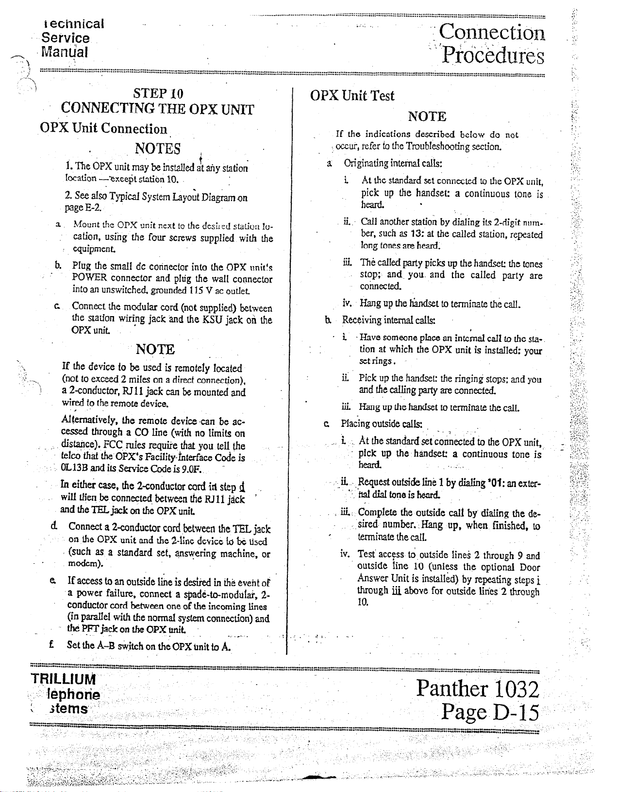
wchnical ..
Service
cl Mam.pl
.\
..“I . . . . . . . . . . . . . * . . . . ..“................~.....~..............~.... “...
. . . . . . . . . . . . . . . . . . . * . . . . . . . . . . . . . . . . . . . . . . . .
<
‘5
.’ 1
CONNECTING THE OPX UNIT
OPX Unit Connection
i. The OPX unit may be inst.clIed at aiy sfatioi
location -?xce$t statitin 10.
2. See also Typical System Layoit Diag&n on
page E-2.
a Mount t!e OPX unit next !o the de.sL-ed station Io-
: cation, usihg the four screws supplied with the
equipment
._......_............. . . . . . . . . . . . . . . . . . . . . . . . * . . . . . . . . . . . . . . . . . ..I.......... . . . . . . . . . . . . . . . . . . . . . . . . . . . . . . . . . . . . . . . . . . . . . . . . . . . . . . . . . . . . . . . . . . . . . . . . . . .._1~
-...- . . . . . . . . . . . . . . . . . . . . . . . . . . . . . . . . . . . . . . . . . . . . . . . . . ^ . . . . . . . . . . . . . . . . . . . . . . . . . . . . . . ..--..
. . . . . . . . . . . . . . . . . _
. . . . . .,
‘I
Cqnnectiqn
: : p~oc$du.es
.*.. . . . . . . . . . . . . . . . . . . . . . . . . . . . . :::::::::::::::::::::::::::::::::-:::::::::::::::::::::::::::::::::~.::::::~:~::::~::::::~:::::::::::::::::::::::::::::.~::::::::::::::::::::: :::::::: ::::::;:::::: ::::::::::::: :: ::::::::::: :: i..
STEP IO
OPX Unit Test
NOTE
If the indications described beIow do not
NOT& ,
;
. . occur, nfer io the TmubIe.shc&ng section.
a Originating internal calis:
i At the standard set connected to the OPX unit,
pick up the handset: a continuous tone is
beard. 6
‘,
ii . . Call another station by dialing its 2-digit num-
bcr, such as 13: at the called station, repeated
long tones are
heard.
: I
:;
I,,.
:i:
I:,
: .,
,’
,,
b. PIug the small dc corinector into the OPX unitfs
POWER connector and phig the wal1 connector
into an unswitched, grounded 115 V ac outlet
c Connect the modular cord
tie station wiring jack and the KSU jack oii the
(not
supplied) between
h Receiving internalcalls:
OPXunit *
NqrE .. _
‘.
. .
I:
If the device to be Used is remotely Iocated
(not to exceed 2 miles on a direct connection),
II
I
a
.’
2conductor. W 11 jack can be mounted and
wired to the remote device.
.>
Alternatively, the
remote
device zan be accessed through a CO line (with no limits on
dis@c~). FCC, r&s requiie that you tell the
--.
telco that t.h&OPX’s FaciIity-fnterface C& is
., OL13B and its Service Code is 9.OF..
-
In eithei case, the 2-conductor cord iti step d
will tfien be connect+ between the RJtl jack ’
and the
TEL&k on the OPX unit
d Connect a 2conductor cord between tie TEL jack
on Ihe OPX unit and the 2-&e device t6 be tised
_ .
, (such as a standard set, wsu[ering machine, or
modem).
e If access to an outside lie is de&d in ihb evetit of
a power failure, connect a
spade-tc-modulti, 2-
conductor cord between one of the incoming lines
c Pladngoutside calls: _ ~
.
stop; and. you. and the called party are
coilrlected
iv. Hang up the tit to terminate the call.
’ i Have someone place an inte;Tlal call to the sta-
tion at which the OPX unit is insWed: your
set rings.
Pick up the handsetl the ringing stops; and you
;i.
and the caIJ.ing party are connected.
Hang up the handset to terminate the call.
iii.
__ ;.
‘i At the standard &t co&&ted to the OPX unit,
.
pick up the.handsetz a continuous tone isheard.
.--ii. ,-Request
o~kide
line 1
by Wing ‘(Ii: an exter-
“. ilaIdiaIto~eishear&
.
iii.: Complete the outside call by. dialing the de-
.sired- number..Hang up, when finished, to
terminate the catl.
iv. Test’ acgss t&outside lines 2 through 9 and
outside fine 10 (unless the optional Door
Answer Unit is install&) by repeating steps i
through iii above for outside liries 2 through
10.
-’
.,: .-
. . . . . . !
.>..:.; /!,.
y.‘.:” ,.,.
:.:::;..
::,:;‘ :;
;.. 1;; s;:,,
..,.,
I.:;
+..: :;c
, 1 . ” .,
- !zsf:;;
- ;$?:Z
I:,i {:.
. ..”
‘,. ‘i.
1 ‘:
:
(in parallel with the normal system connection) and
th6PFrjackontheOPXlInit
-.
f Set the A-b &itch on thd
OPX
tinit to A.
-.. _. .
-........-” . . . . . . . . . ..““.......““,” --___-.
“..1--‘.................... . . . . . . . . . ..I.... I..__ -.I . . . ..- ~.._” -... _...“I..“...-- . . . . ..-..... “..““.” .-....- I._ .-..,............,. I . . . . ...” ..-.................,...., r.r: ._-. “...“” ._..... I.” .___..-
---“..“......“..“...“.....L . . . . . . . . . . . . . . a.“..,“.“..”
..-.. “.-_ . . ..-1...........-........ i . . . . . “..“.,_ . . . . . ..-.-
,..,.; . .._.___.._ “__
yyLLIUM ‘,
t,;.‘: :lt$harie ..
;tems’z‘ ’ .. .. .-
\
E~iii:~~.~~~“--...“.-..---.~-
:..
“..
:: ‘..,
<S : ;
‘.,~?I.‘.‘:~y~,:‘.-> .,,,“. -..
;.yy.: ,.?‘;: ,;..,::: ~ : .i,: ,f: :: .$ ~&$~,,:
,..;: .;.;, .i .; . ‘ ,.I$.!. ~.,3.,ifii;c\~, ‘i’,?. : ___.__, ..;r,::;-, _.I, -..‘A . .
,~.,<,,;.;; :“,‘.‘,. ~..,Tr ,.,. .^c?c-cr,r .-.-,
.- -..,.;,..’ .:
.- , ‘,; ‘1 ,.
-__f
..,_, ,. y’. --”
L ,,., ;;;:.‘:
‘:
. . : .
. ,‘.... ‘.
: ;.. .’
,-.. ._
,...
..,(
.,; ..- .> . .._ <,.,; ,,-..-. .i :,=:G.’
__ :: :
.-.-.......C1”.““....“.“~.~...
,..~,ib,?,,~_ s,y-p ‘;” ‘_
_.- .:
.’ .‘I. L. _,
. . . :
.+....A
.. Panther
‘. .p@)-‘i5
. . . . . ........e.l..^-“.... . . . . . . “-.-...-l-.“.-...l-...“.-.---.~ -.--- -.-_A
. . . . . . -- ..-. ~.“_...__..... . . . . -.-._.,- -........ ,...I . . . . . . . . “” .,........-....,.. ~nn”,l,u” ,_.,.
,; r. ,.
._ _ _.i.,L..~.-. .+,...r ..,-v-
_
”
.1- . i. ?I
,.
_L,
;: __ .- _
,’ !’
* ,,_-.. &_” ..,.._,_., ~..~.. .,._ 1’ -:.- -.:--.-. ,‘-T-‘-..,:--, _- i- ._
:.
. .
- .I’, :. ,,
i-032
:~=~-~:~=
‘.‘Ci
/
.~ t, .,
_
_‘..
..- :- . . . . . :c-:,::,’ ;,-
Page 30

STEP 11 ’ ‘.:
COI’JNECTWG
WESMDRU’+iTI’
:; .
(part number 90-0227 only)
._
CAUTION
Power should not be appIicd!to the KSU when
instaUi.ng the SMDR unit
Connect an RS-232
the bottom of the SMDR unit
vice (terminaI or printer).
Set. @e appm@iate baud rate switch (300,600, or
1200 bps) on ihe SMDR unit top match tie require-
ments of your r&rding device.
Set the BAVRY switch on the SMDR
cable bctwcen the connect& at
and the
recording de-,
unit tn
'
NOTj3S
1. At a minimum, pin 3 (Rcce$ed Data)
-pin 7 (Signal Ground) must be wired in the
cable connecting rhe SMDR unit and the
recording d&ice.
2.
Also, depending on the characteristics of the
recording device, other pins may need to be be ~
jumpered, ground&i, or raised - consult your
recording device’s m&nic@ ma.nuaI or your
recording device manufacmrer’s customer
service.
.: J.2)
3. See also the specifications on page C-l
the Typical System
Ec2--
Layout Diagram on page
-:;
SMDR Unit jhstallatioh
a Mount the S&fDR unit Mow the KSU on the ply:
woodbackboard.
b Connect the special nbbon cabIe (.suppIied with the
SMDR unit) between the connector at the bottom
:..
of
the KSU and the connector at the top of the.
SMDR unit.
.I,. Typical Outgoing Call Format (all recorded on one line)
[monthJ/[date] [time of day] [length
07/23
02:25P 00:02:24 014
of call] [station] [not used] [telephone number] [outside 'line] [account]
and
and
If
noi
performed already, go to Step 4 to apply
power to the system and to conduct the initial system ~sts. When Step 4 is completed, return and
perform the SMDR unit test procedure (found
bdOW).
“NOTE .:
Ge time of’day, date, month, and year are all
programmed into the SMDR from station 10.
ST the operating Jnspuctions section.
a Place an outside calI: verify that the +I! informa- t
tion is recorded, as shown below. :
.
h _ Have someone piace an incoming call
-.
the incoming call - enter an aEou.nt number (see
. .
. . . . operating InstructionS section): verify that the call
_ information.
shown below.
.
:. :
and. account number
000 17145573300 TOO1
-
and -during
is recorded, as
.
Typical
Imonthl/Idatel
07/23
,:,Finther
[time of day] [length of call]
03:&2P 00:11:53
w
._ Z'
.-
\
1032.
i dge l-J-16
*...-.- . . . . . . . . . . . . . . . - . . . . . . . . I . . . . . . . . . . - .^.........." . . . . . . . . . ..-........-... "._.-.-._ ..-... * . . . . . . . . . . . . . . ..-.. __ ..*...
. . . . . . . . . . . . . . ..-.-Wm.... . . . . . .".--..--I"."..-." . ..-.......-_-... "-"
. ..-.
Incoming
Call Format (all recorded 06 one line)
[outside line] [seconds to answer]
TO03 029
SMDR’Frintout For.&& 1’
’ ..
.. .,: .?$s;l$;'
. .
.._." . ...*-.. -..-.--.- ll-.l.-............-..-.. - --... --..-..
I............ - ..-.-- . ..I" . ...,." ..,,...... U. . . . . "-- . . . . -f..-
[starion] [account]
011 A1234
TRILLIUM ' -'
. . . . . . .i ..,.. _. .
.~l:.~P.-...-."
:’
iJ
Page 31

CONNECTING THE
‘POWER FAIL TR.hlSFER UNITS.
.
Perfom the fbllowing procedure only if you
wi& to install the.optional Power Fail Transfer
Unit If such is the case, then this procedure
should be followed iri lieu ofStep 2.
NOTj3
c Connect the 2-conductor special cable supplied
with the 2nd Power Fail Transfer Unit, as follows:
i. At the 1st Power Fail Transfer Unit,
one end of the special cable to the connector
connect
ldxled J.
-.r
ii.
At the 2nd
thk other end of the special 6abIdinto the con--. L
nectar lab&d CIW.
Power Fail Transfer Unit, connect
- .
I
CAUTION
Power should not yet k applied to the KSU.
Power Fail Transfer Unit Xnstathtion
-NOTE
See also -?he Power Fail Traxsfer Unit diagram
in the System and Set Layout section
a. Mount three Power Fail Transfer Units in tie upper
right comer of the plywood backboard.
b. Connect the 2-cont?xtor special cable supplied
with ihe 1st Poker Fail Transfer Unit, as fol.Iows:
.
i.. At the KSU, connect one end of the speci:.
cable to the ctinector la&d POWER FAIL.
: L ii, At the 1st
. . >. :... the othti.end of the special qable into the con-
nectar labeled CNK..
Power Fail’ %a..nsfer
\
Unit,
connect
d Cohnect the 2-cchductor sp&l cable supplied
With the 3rd Power Fail Transfer Unit, as .follows:
._ . .
I,
At
the 2nd Power Fail Transfer Unit, connect
one end of the special cable to the connector
labeledCNJ.
.
ii.
‘At the 3rd
ihe Other
nectcxIabeIedCNK. ’
Install two
e
i Install a 50-pin R321-to-modular adapter that
has 5 e&h R.314 jacks on one of the RJ21 connectars on one of *he 25-pair ables; the other
Power FaiLTransfer Unit, connect
end of the special
.
adapters and‘two 25-pair cable+:
cable into the co&
end of the cable terhina!es in a: 50-pin connecfor that connec& to the RJ-21 jack that ties
_ *
the incoming lines.. This will be called the 1st
._
adapter. ‘.
1 ., ii ..’ Install
. I
a B-pin
has 5,each lW4 jacks on one of the RJ21 con-
ntxtms on
RT2l-to-ktiuIar adapter that
a 25-p&r cable:. the other end of the
,’ :. cable kminates in another 50-pin RJ21. con-
nectar that plugs into the KSW connector
labeled CO1 tb COlO. This will be called the
+ 2nd adapter.
.
;
-
. .
Page 32

f. Route the incoming lines
.~,,,-...i:~-,-i-~.-z’~~~?~.~~~~;’,~:::
1.,/..,..;111:.
Transfer Units:
t
i. Connect a 4-conductor modular cord between
the. 1st adapter’s IU14 jack at which incoming
Iims 1 and 2 are term&ati and the 1st Power
FaiS Transfer Unit jack Jab&I CO1.2.
ii. Cocmect a +conducmr m&L&r @rd bqxeen
( t&e 1st adapter’s RJ14 jack at y&h incoming
lines 3 and 4 are terminated and the 1st Power
Fail Transfer Unit jack labeM 03.4.
!Q
the Pewer Fail
g. * Poute’ihe I’
tothe2ndadapter:
i. Connect a 4-conductor modular cord between
.I and 2 (the first jack). :
ii. Connect 3 4-conductor modular cord between
,3and4 (thesecondjack).
mes from the Power Fail Transfer Units
the 1st Pokier Fail Transfer Unit
.X1.2 and the 2nd adapter’s IUl4 jack for lines
L
the 1st Power Fail Transfer Unit jack lab&d
‘X3.4 and the 2nd adapter’s R314 jack for lines
jack
\
IabeIed
’
.\
‘,
,! -.
iii. Connect a ll-conductor modubr cord between
the 1st adapter’s RJ14 jack at which incxxlng
iv. Connect a 4-conducmr modular cord bet&en
the 1st adapter’s RJ14 jack at which incoming
lines 7 and 8 are terminated and the 2nd Power
Fail Transfer Unit jack Iabeled C03.4.
Y. Copxct a
the 1st adapter’s RJ14 jack at which incoming
- ~9~d1Oinehmbateitithe3rdPower
F~J’ransferU&j-&&b&iCO~.2. :
4conductor modular cord between
iit. Connect a 4-conductor modular cord between
the 2nd Power Fail Transfer Unit jack labeled
ml.2 and the 2nd adapter’s RI14 jack for lines
5and6{thetfrirdjack). ’ .
iv Connect a 4-conductor modular cord between
the 2nd Power Fail Tmnsfer Unit jack Iabeeled ,.’
TK3.4
and the 2nd adapt& RJ24 jack for Lines’.’ ‘.i -,i
7 and 8 (the fourth
Y. Connect a 4conductoF modular cord between
the 3rd Power Fail Transfer Unit jack labeled
1x1.2 and the 2nd *t&s RI14 jack for lines
9 @d 10 (the fifth jack).
_ -
- L Jnstall ten stun&t-d t&phones (2-wire sets) in tenyenient or sfxategic locations.
i. . . . Using 2&1ductor, modular cords, conneuthestan-
i -: dard sets to the jacks labeled TlT through T4T on
the 1st and 2nd Power FaiI Transfer Units and to
the jacks iabeled TlT and T2T on the 3rd Power
Fail Transfer’Unit.
jack).
_, -. -
/
_
.
.
--*+--*-‘**-*‘*” . . . . . .“““.....u.u.~...“r,,, -..-...-.... I -......... __.” . ..--.- I-..” ..--...-..._..........., i..~ . . . . . . “_^“” . . . . . . . . . . . . . .
.-..--...““....” . . . . ..-..“-.“...1...-..-.....,--”
:.:
,%.T,anther
1. i& D: 1.8
..f.“.... . . . . . . . . . . . . ..“......... .--_
.“...‘...““.“-‘..‘.-.-..-.----~~~:~~.~~.-” ..^. ---“.” ._...I_.....” . . . . i _........_....._.” ._......_................-.......... _ _.._._.... “...
_’ -
.: ‘.‘I ;. :’ ,... .~
.’
.‘: ‘--.‘.T;i,l.,;,-I .._... ‘:
;‘. %,i;;:s,.+ .,.. ~ ._.., .;;:, “.., _ ,,
.:;;.i;\i:-:.“~~_., ; ;.: ::i‘.;~--.‘..:i’-:.t ” )_ .; .:. :. ‘,.,C,
.-;.:~+~;,.Yq..: .:. .:c ‘.:“:“ -. .:.
.,.- ; -,. ;, ;,.: ,,,;,-+:..:+ -. :, :
TC. ..:~~--~:..,r.-2.~.~i..;..I..~...:. .--..+y:;,-
;:‘-~.t‘.,;,..~-.r.,~ . . -..-_ I
”
*.i+jA...-:~ j .,.- ~..;~;.&.‘,.,~~ I ,,.‘~-:-.--‘:;
1032
._
._. -. ‘. ,:,,
._
ii _._._ -..:; :..:,: ~.
-,: ;;; ._,.:
=I.
,),, c,,&;s>,, .::.:e ;&.:zi::;:.“:“~.; ‘;.: t,. .“’ j
: ..;
:.. .‘..’
‘,
:
.$. j’,: .:..,.-. .-.. 1
_ :;. ( :::.~:.:~.,.~~~.:.,~~~ .y .; ...., y:,‘~,<~;:,:,
.l--;-- --
.I
‘e.....“..“...........“....-s......” . . . ...” . . . . . “..I...”
,............,................ _ . . . . . . . . . . . . .
. . . . . . . . . . . . .
. . . . ..‘............ *...,...
. .
L ..,,......,. ;.:::;~~.;;:-:n~..-
.--..-.---
--“.. ’
TRILLIUM. i2
Telephone -.
Systems
-.-.--I.“-““--.-“..-.-“--.----.-..- -.-. _ .-......-.....- “-..~-‘:‘““~..“;~.~--~-”
.:.
.’
. . ,;‘,’ “;‘, ,_ ,, c ,- r;. , is. ‘.P:‘:‘-
,.c :-. , 7..
.;-;;>.- :, ,I_+~:c :,y’ i
. ., ,:--
:
.‘. ‘,
.: . .
_, ,: ,.,_,,.,, :-:.,:. .,5.; ,:; 7.c I, ;:
_’
.,“I, .,
_
:
. . . ‘.,
, _“. ,,:; ,(.,.. ;?,ll-...,..‘.il.i:“.~~,::.
-.-,.~ -_-._ll.l.”
,?
_,. .’
:
_ . . . . ;,<,;,y$,<:
.. .k y,. :; y-. /: ,,.,..
:.
Page 33

. . . . . . . . . . . . . . . . . . . . . . . . . . . . . . . . . . . . . . . . . . . . . . . . . . . . . . . . . . . . . . . . . . . . . . . . . . . . . . . . . ..-.................
..-.......................................................-......
.;‘-‘.
--I:‘:,,-
,.‘.::i~,.“‘,S:‘;.~T:‘;:
.
--~~.-...~:~;--~,:‘
,-
..
:
. . . . . . . - . . . . . . . . . . . . . . . . . . . . . . . . . . . . . _ . . ..-...........-....-..-.......................
Qmne~tion
.‘. .,,
.
Procedtif&
. . . . . . . . . . ::
Power FaiI Transfer
a With power still removed f?om the KSU, the stark
dard sets just installed stiould ail be receiving dial
tone -
calIs. If not, refer to the Troubleshooting section.
b. Proceed to Step 3.
and be able io originate and receive outside
Unit Test
. .
,
.~.......“............. . . . . . -.........* . ..I..........” . . . . ..-._----....._...-..” ,,...,._ _ . . . . ..(..
. . . . . . . . . . . . ..“.........‘.‘.............................. . . . . . . . . . . . . *....,I... I..........,............... * . . . . . . . . . . . . .
~RILLlUhj .
Tstephane
‘stems
. . .
.““““...........;..............~--..~~, . . . . -.......--&. . . . . .
. ..~................................ . . . . O...“...“...” . . . . . . . . . . . . . . . . . . . . . . . “__ . . . . . . . . . . . . . . . . . . . . . . . . . ...” . . . . . . . .
., ,-....
“..._ . . . ..-. “..i . . . . . . . . . . . . . . . . . . . . . . . . . ..--.- _ . . . . . . . . _ .
.,
,
,
.:
.:
_
p.“*“““..‘“- . . . . . . 8.9 . . . . . I.
. . . . . . . . . . . . . . ...” . . . . . . _ . . . . . . . . . . . . 1..1..,... I ,......,,...........,..........,..,.., * . . . . . . . . . . . . . . . . . . . . “.” .._...... ~~~-=~.::
.,
. . . ..l...“...“... . . . ...” . . . . * . . . . . . . . . “.“, . . . . . . ..- “.“.” .-..---..--
. . . -i..- . . . . “..._ . . . ...” . . . . . . . . . . _ . . . . . . . . . .._-._.._
_’ ,“.
:,
. .
,. .-.
0
0
\
Panther 1032 :.
’ ._ Page .-j)+)
“..” . . . . . . . . . . . . . . . . . . . . . . . . . . . ..-..........-.--_
.., : ;.;.sz:. :. :._,
_: : _) 1:
. . _.:,,.. . ..i .,
. . ,.
..I ..:.,ic.;
,.:-
.,,: _’
~z,:;‘.:..
.-
.,_’ .,
: ,. ,i,: :;.7 r.,~,~.:;~.,-t..:.,!’ . ,. :>,,:.,, :1 ,_l. .., .b. L.-L
;I.: . .._ I.) : 1, ,.:r;;;~;:.,,::i,r!9i.l ,I ,,/,.
..“; _ .c..:;, .,./
: &<Lr.~. ;a,: :.. ,;;
>, :
9:
~,.,.
1. “;
--“.--.-.~.~;*~~:
,... ~‘I’
..,,I -. ,;
. . . ..-
, .,-~,-.-. ” -.,
-,
,.l ,i-.:py~. ..,I ,,.‘V--. ,. .-
.., ./
. :
/’
:.
-,
,.i. .:
;‘:
:
. .
,‘i‘ .
-.
:...
4:;
.-
Page 34

. . . . . . . . . . . . . . . . . . . . . . . . . . . . . . . . . . . . . . . . . . . . _.-
. . . . . * . . . . . . . . . . . . - . . . . . . . . . .
..-..........
I . . . . . .
__............_,................
_)"
.-..-.-...........-.-.-..................-............
_ . . . . . . . . . . . . - . . . . .
-.-
. . . . . . . . . . . . . . . . . . . . .
I.-...-.--...-.-....-..
.,......
-I........*
. . . . . . . . . . ..*..-.-...-.I.
. . . . . . ..".f...
. . . . . . . . .
..."
. . . . .
I."
.-..-.....-
",".,"
.-.-
~.~-"
. . . . "I . . . . . .
?.."
.
..--....
". . ..-....
"...."...."
. . .
..-.
"..
. . ..-.................
'-.~..a."‘.-"-......-..
.
.,',
.',
COnfiection
STEP 13
-iNSTALLING
AN EXTERNAL
JIMPLIFIERISPEAKER
Tqdwical ‘:,
_ I::1
If an external amplifier/speaker is to be instalkd at a given
station, the the stand&d station wiring and Set installation
procedures must be m&ied for that station as follows (see
also t&3 diagram to the right):
a Instead of mounting a 4conductor RJ14 jack at the
station location (see Step 3 hz, mount a 6-conductor
RJ25jack
NOTE
The 4-conductor station wiring cable between
the 66-block tcnCna$ and the station wiring
&:I, 4-,17- . .L
j:;.ck s
U= .u.Lvw3 ~;s c!&aiIs given in the station
wiring table on pages D-5 through D-9 r with
the 4 wires still running from the same 66
block
terminals and being inst.alIcd color-lo-
’ coIor on the jack, green-to-grtin, red-to-red,
! black-to-black, and yellow-toyellow.
b. Connect the external amplifier to the bIue and
white tennina.& of the RI25 station wiring jack
-.
c Instead of using the 4-conductor mod&r cord sup-
plied with the Set (see Step 4 g), use a standard 6conductor moduIar cord to connect the Set to the
station wiring jack
. by plugging
6-conductor ’
podular cord
in here
\
:,
-. . .
,.
J
NOTE
The extemat ampIifier/sp&er is now connecttxltotheSetsipeakerterminals.
d Check to see that signaling and voice messages
norma.lIy he&d over the Set’s speaker will now be
heard over the external amplifier/speaker.
‘c To return the Set to its normal operation, simply re-
pIace the 6-conductor cord between the Set and the
station wiring
originally supplied with the Set.
;:‘:&ther-
i dge
. . ..-....“..‘....” . . . . . . . . . . . ;...i., _..............” . . . ...*. I . . . . * ._..........” . . . . . . . .
-----.-- . . . . . . ~.“......“.“.......“....“.......” . . . . . . . . . e.... .
.,
:..;,,: #...... 1..,,:, ,.‘3::. ,....,,~ ‘-“.:;: ,_.’ 1, ;.;. ,_. ,: : ._
‘....‘~:.-,:“:_7:i;:.;,~,,~~~ ~~~~.~..:~~,~~r:.,~.l.;~.~-I.L .<‘.~ --
,.. . . .
. . . . ., . . ,,.
,-_ ‘.
.--.,..;~,n-.~~~,~:~~-.
D+2()
.;_ i,. I. 1 _ _
.- :
.I .I : -. L ; ,‘. . . ” .-.
:- ,:.... z., .-.‘,.:-
.,,yz.,-, _. ,i..;*; _ ..,.,,, :.,c’il,.-,,. .:. .-._ - :. .-. . .
.,
- i
,.,.
jack
1.032
with the 4-conductor that was
..
; :
. . . . . . . . . . .._..........................” . . . . . . . . . I . . . . . . . . . . . . ..--- -” -................................ -----_ . . . . . . . . . . . ..I... _..“- -..... - ..--.... :..;
’
‘~ :_. .,
..,_ ‘..,. .: . _.
.I ... -,.
. . . . . r...--& -.,. “-.“..“...” ._..” ..-..-.- . . . . . ..I..... . . . . . . .“..~...“... . . . . . . . . . . . I . . . . . . . . e..... . . . . “......‘y...,‘* . . . . . . . ..“-“..““..“.-....... _
.,, ‘-
.;.q.. ,;I:.
I ~i,--L;;- . . . . zz. .I ,,..,,., .-1
. ...,.
-
_-
., ,I ..I
.,
‘.
:: . ...’ ,) .-
/>:z:.:-~--~?:- ‘i ,7xI :.?:?irT-- ‘--
.,I.
,..,.,‘. .-.,; ..,
. . . . my;:‘.“;
:. “‘, i.- ‘-2 .>‘-,;:~.~+ ,:.: ,._ I,:.:
-l.;lc- :. ,;: .: .‘;-:‘r..-..,;, .,
..I ,.. :. .,:,;
.‘. ; ;:,;I.-
:
Page 35

I Cblll IlbQl
.._-............................................-...........................
:..::-:::::::::‘-::::::::::::::
..-.................................................-.....-..........................
:::::::::::::::
..-...................................................................
1. .S(+[&
System and ;.
-- .?Maniiii
1 ‘- I.... . . . . . . . ..-.............................................
. . . . . ..I..... - . . . . . . . . . . . . . . . . . . . . . . . ..*.....* . . . . . . . . . . . . . . . . . . . . . . . . . . . . . . . . . . . . . . . . . . . . . .
- --..
. . . . . . . . . . . . . . . . . . . . . . . . . . . . . . . . . . . . . . . . . . . . . . . . . . . . . . . . . . . ..-........-. I.-...I . . . . .
,....._......... . .
.*. . . . . . . . . . . . . . . . . . . . . . . . . . . . . . . . ..-............................................. . . . . . . . . . . . . . . . . . . . . . . . . . . . . . . . . . . . . . . . .
cot
TO
co10
Set Lay0u.t
..A... .,.......................,. ~
. . . . . . . . ..__ Q
From g
Zentralg
‘.
,-
: i
$1
;z
?
?$
; :
Non-Handsfree Set
‘A :
T l ..(
, .‘
*---.-.-“.“.^.-..-.“- . . . . - . . . . . - . . . . . . . . . . . . . I...” . . . . “I . . . . . . I...” . . . . . . . . . . . . . . . . . . . . . . . . . . . . . . . . . . . . . . . . . ..-... I .._.” . . . . . . . . . . . . . . . . . . . . . . . . . . . . . . . . . . . . . . . . . . . . . . . . . . . . ..................-.................. i...r .._.” .................._
‘*.*-*......-...“..- . . ..I.....................” . . . . . . . . . . . . . . . . . . . . . . . . . . . . . . . . . . . . . . . . . . . . . . . . . . . . . . . . . . . . . . . . . . . . . . . . . . . . . . . . . . . . . . . . ” . . . . . . . . . . . . . . . . . . . . . . . . . . . . . . . ............................ ...,...,..............,...........,,............” ....,....,...........”
i TRILLIliM!
.’ :-Telephone
ystems
. . . . . . . . ..““....-....“-...
. . . . ..-I...-..“..-...- . . . . . . . . ..” . . . . . . . . . . . . . . . . . . . . . . . . . . . . . . . . . . . . . . . . . . . . . .
TYPICAL SYSTEM LAYOUT DIAGRAM
“-- . . . . - . . . . . . . . . . . . . . ..“.I . . . . . . . . ^.._ . . . . . . ..-....................................-...-.-.. “I
DSS/BLF Unit
(Standafd Components only)
. . . . . . .
. . . . . . . . ...”
” . . . . . . . . . . . . . . . . . . . . . . . . . . I . . . . . . . . . . . . . . . . . . . . . . . . . . . . . . . . . . . . r.l’:: :::: L’
Split
66-block
-. _. .,.
Panthei.l&-. ”
Page
E-J
.
t
Page 36

. . . . . . . . . . . . . . . . . . . . . . . . . . . . . . . . . . . . . . . . . . . . . . . . . . . . . . . . . . . . . . ;;::::::::::::::::::::::::::::::::::::::::::::::::~~:::~:~:~:::~~~ ::::: :::::::: ::::::::: ::::::;::::::::
..~.........~.............~............................................................................................................................................................~.~~
,::“::“::::::;::::::L’: :::::: y-:: :::::::::::: :::w:: :::: :::~:“:::L’::::~~~;~::::
System and
. Technical
Service
C: et. Layout
-7
.‘.........‘...........‘....‘.‘........”’.........‘....... . . . . . . . . .. . . . .
.;........................... . . . . . . . ...* . . . . . ..a..**. . . . . . . . . . . . * . . . . . . . . . . . . . . . . . . . . . . . . . . . . . . . . . . . ( . . . . . . . . . . . . . . . . . . . . . . . . . . . . . . . . . . . . . . . . . . . . . . . . . . . . . . . . . . . . . . . . . . . . ..............................................................
.I
12 AWG
copper
wife
,Red(i)J.To f _I
external i
i
Manual
. . . . . . * . . . . . . . . . . . . . . . . . . . . . . . :::::
‘I
/ 6-
conductor.
cord
2-wire
I cable k
RS-232 cable
(not supplied)
f
TYPICAL SYSTEM LAYOUT DIAGRAM (Optional and External Components only)
. . . . . . . . . . . . . . . . .
. . . . . ** . . . . . . . . . . . ...* I . . . . . . . . . . . . . . . . . . . . . . . . . . . . . . . . ..-.............-...........................................................................................................................-........... :,“^,--
r-_--ffnther 1032
. . . . . . . . . . . . . . . . . . . . . . . . . . . . . . . . . . . . . . . . . . . . . . . . . . . . . . . . . . . . . . . . . . . . . . . . . . . . . . . . . . . . . . . . . . . . . . . . . . . . . . . . . . . . . . . . . . . . . . . . ....... . .......................... _ ............................................................-.............
TRILLIUM (
I. .
4
-_..
lefephone :
Page E-2
Sjfstems
0. ,_:
-3
3
Page 37

Page 38

Page 39

Page 40

Page 41

Page 42

Page 43

Page 44

Page 45

Page 46

Page 47

Page 48

Page 49

Page 50

Page 51

Page 52

Page 53

Page 54

Page 55

Page 56

Page 57

Page 58

Page 59

Page 60

Page 61

Page 62

Page 63

Page 64

Page 65

Page 66

Page 67

Page 68

Page 69

Page 70

Page 71

Page 72

Page 73

Page 74

Page 75

Page 76

Page 77

Page 78

Page 79

Page 80

Page 81

Page 82

Page 83

Page 84

Page 85

Page 86

Page 87

Page 88

Page 89

Page 90

Page 91

Page 92

Page 93

Page 94

Page 95

 Loading...