

Page 1
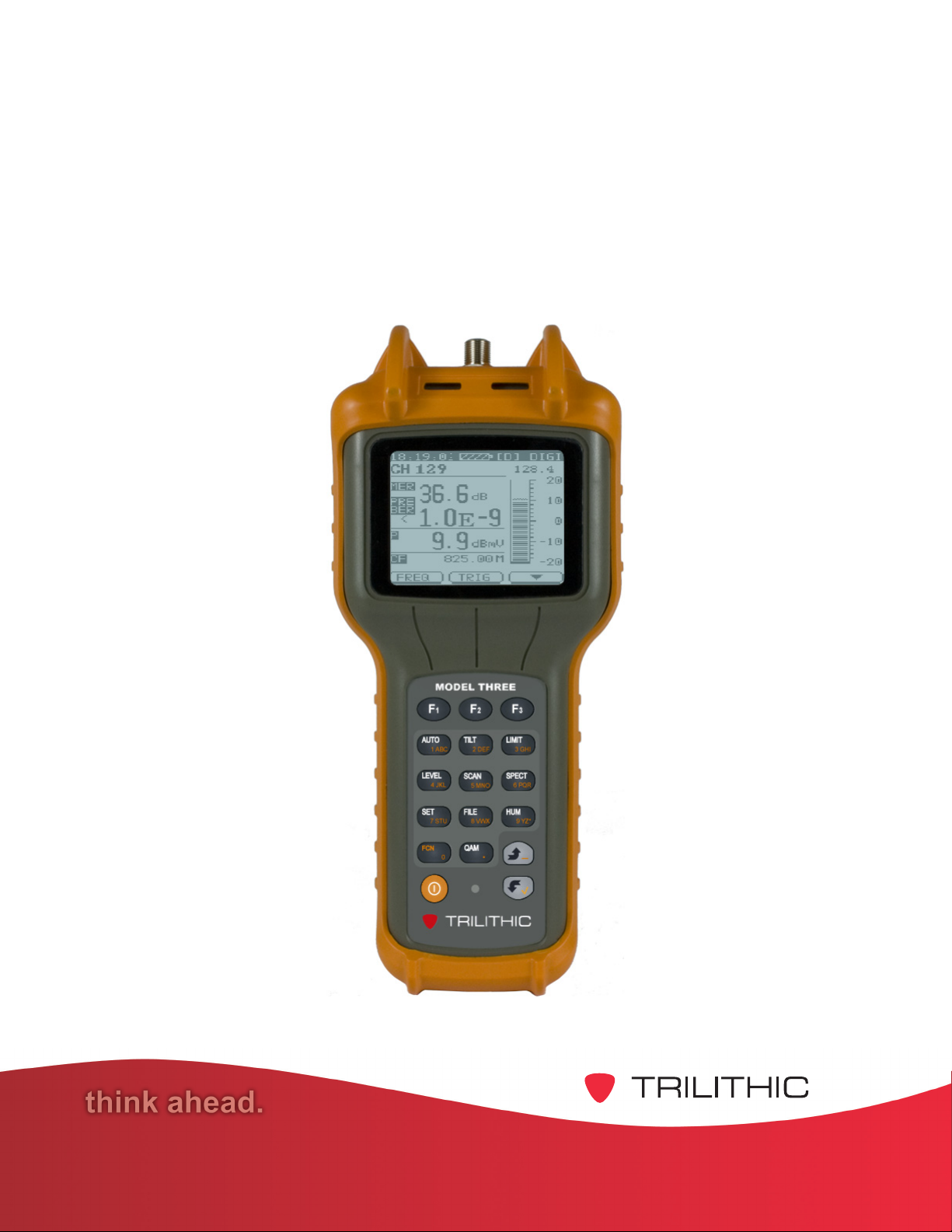
Model Three
Signal Level Meter
Operation Manual
Page 2

Page 3

Trilithic Company Profile
Trilithic is a privately held manufacturer founded in 1986 as an engineering and assembly
company that built and designed customer-directed products for telecommunications, military and
industrial customers. From its modest beginnings as a two-man engineering team, T rilithic grew
over the years and broadened its offerings of RF and microwave components by adding
broadband solutions to its product line. This was accomplished with the acquisition of
components manufacturer Cir-Q-T el and instrument s manufacturer T exscan.
T oday , T rilithic is an industry leader providing telecommunications solutions for major broadband,
RF and microwave markets around the world. As an ISO 9000:2001 certified company with over
40 years of collective expertise in engineering and custom assembly , Trilithic is dedicated to
providing quality products, services, and communications solutions that exceed customer
expectations.
Trilithic is comprised of three major divisions:
• Broadband Instruments and Systems
Offers test, analysis, and quality management solutions for the major cable television
systems worldwide.
• RF Microwave Components
Provides components and custom subsystems for companies specializing in cellular ,
military , and other wireless applications.
• Emergency Alert Systems
Leading supplier of government-mandated emergency alert systems used by broadcast
TV , cable TV, IPTV , DBS, and radio stations.
• XFTP
Offers a specialty line of field technical products for cable operators and technicians, as
well as a line of products for installing electronics in the home of the future.
Model Three Signal Level Meter - Operation Manual
1
Page 4

Table of Contents
1. General Information..............................................................................................................5
Helpful Website .....................................................................................................................5
Where to Get T echnical Support.............................................................................................5
Conventions Used in this Manual ...........................................................................................6
How this Manual is Organized................................................................................................6
Precautions ...........................................................................................................................7
2. Introduction...........................................................................................................................8
What is the Model Three? ......................................................................................................9
Features ..............................................................................................................................10
Tilt and Favorite Group Display.......................................................................................10
Single Channel Display ..................................................................................................10
Single Channel Spectrum ...............................................................................................10
Scan Display..................................................................................................................10
Spectrum Display ...........................................................................................................10
Hum Display...................................................................................................................10
QAM Measurement ........................................................................................................11
Data Logging .................................................................................................................11
Limit T est........................................................................................................................11
Auto T est Programs........................................................................................................11
Voltmeter........................................................................................................................11
File Saving and Viewing.................................................................................................12
Equipment Supplied with Y our Model Three .........................................................................12
Accessories and Replacement Parts for Y our Model Three..................................................13
3. Walkthrough........................................................................................................................15
Identify Components ............................................................................................................15
Key Pad .........................................................................................................................16
Navigating Functions ......................................................................................................18
Display Screen Description............................................................................................20
Battery Charging..................................................................................................................21
Model Three Signal Level Meter - Operation Manual
2
Page 5

4. Setup ...................................................................................................................................23
Overview .............................................................................................................................23
Information...........................................................................................................................24
General................................................................................................................................24
Backlight ........................................................................................................................24
LCD Contrast.................................................................................................................25
Shutdown Time...............................................................................................................25
T emperature Unit ............................................................................................................25
Date and Time................................................................................................................26
LCD Test ........................................................................................................................27
Upgrade.........................................................................................................................27
Prior Menu .....................................................................................................................27
Measurement.......................................................................................................................28
Transmission..................................................................................................................28
Level Units .....................................................................................................................28
Single Frequency Setup .................................................................................................29
Limit Setup.....................................................................................................................30
Reset Max Hold..............................................................................................................31
Voltage...........................................................................................................................31
Hum Frequency ..............................................................................................................32
Prior Menu .....................................................................................................................32
Channel Plan .......................................................................................................................33
Select User Plan ............................................................................................................33
Channel Numbers...........................................................................................................33
Learn User Plan .............................................................................................................33
Edit User Plan ................................................................................................................35
Tilt/Level List...................................................................................................................39
Load Defaults.................................................................................................................40
Prior Menu .....................................................................................................................40
Model Three Signal Level Meter - Operation Manual
3
Page 6

5. Basic Operation ..................................................................................................................41
Fast Setup...........................................................................................................................41
Single Channel Level T esting ...............................................................................................42
TV Channels...................................................................................................................42
Single Channel Spectrum ...............................................................................................44
Single Frequency Channels ............................................................................................45
Digital Channels .............................................................................................................46
Frequency Mode..................................................................................................................47
Channel Scanning................................................................................................................48
Display Limits.................................................................................................................49
Limit T esting ........................................................................................................................50
Frequency Spectrum Scanning ............................................................................................51
Hum Measurement ..............................................................................................................5 4
QAM Measurement..............................................................................................................54
QAM Channel Measurement...........................................................................................54
QAM Frequency Mode ...................................................................................................55
Spectrum Analyzer Display .............................................................................................57
QAM Constellation Display (Optional).............................................................................57
Tilt and Favorite Channel......................................................................................................58
6. Advanced Operation...........................................................................................................59
Transmission Characteristic Test .........................................................................................59
Auto T est .............................................................................................................................62
QAM Parameters ...........................................................................................................64
Level Parameters...........................................................................................................65
Spectrum Parameters ....................................................................................................65
Limit Parameters............................................................................................................66
Tilt Parameters...............................................................................................................66
Hum Parameters ............................................................................................................67
File Saving and Viewing ......................................................................................................70
Saving a Test Record to a File ........................................................................................70
Viewing File Records .....................................................................................................71
Auto T est Records ..........................................................................................................74
7. Specifications .....................................................................................................................77
Warranty Information ............................................................................................................81
Model Three Signal Level Meter - Operation Manual
4
Page 7

Chapter 1
1. General Information
Helpful Website
The following website contains general information which may be of interest to you:
http://www.trilithic.com
Trilithic’s website cont ains product specifications and information, tips, release information,
marketing information, Frequently Asked Questions (F AQs), bulletins, and other technical
information. Y ou can also check this website for product updates.
Where to Get Technical Support
Trilithic technical support is available Monday through Friday from 8:00AM to 5:00PM EST.
Callers in North America can dial 1-317-895-3600 or 1-800-344-2412 (toll free). International
callers should dial 1-317-895-3600 or fax questions to 1-317-895-3613. Y ou can also e-mail
technical support at techsupport@trilithic.com.
For quicker support response when calling or sending e-mail, please provide the following
information:
• Y our name and your company name
• The technical point of contact (name, phone number , e-mail)
• The Model Three serial number , firmware and hardware version numbers
• A detailed description of the problem you are having, including any error or information
messages
Model Three Signal Level Meter - Operation Manual
5
Page 8
How this Manual is Organized
This manual is divided into the following chapters:
• Chapter 1, “General Information” provides Trilithic cont act information and describes how
this Operation Manual is structured.
• Chapter 2, “Introduction” introduces the equipment and features of the Model Three.
• Chapter 3, “Walkthrough” describes the components of the Model Three.
• Chapter 4, “Setup” describes the steps needed to perform the setup of the Model Three.
• Chapter 5, “Basic Operation” describes how to use the basic features of Model Three.
• Chapter 6, “Advanced Operation” describes how to use the advanced features of Model
Three.
• Chapter 7, “Specifications” shows the technical specifications of the Model Three.
Conventions Used in this Manual
This manual has several standard conventions for presenting information.
• Connections, menus, menu options, and user-entered text and commands appear in bold.
• Section names, Web, and e-mail addresses appear in italics.
A NOTE is information that will be of assistance to you related
to the current step or procedure.
A CAUTION alerts you to any condition that could cause a
mechanical failure or potential loss of data.
A WARNING alerts you to any condition that could cause
personal injury.
Model Three Signal Level Meter - Operation Manual
6
Page 9
Precautions
The battery MUST be charged with the AC to DC power adapter
and battery charger provided with the Model Three. Using any
other adapter/charger may damage the battery.
The maximum input voltage to the meter is 100 V (AC or DC).
A larger voltage will damage the meter .
The accuracy of the meter may be affected when in a strong
electromagnetic field.
Do not use the Model Three in any manner not recommended
by the manufacturer.
Model Three Signal Level Meter - Operation Manual
7
Page 10

THIS PAGE LEFT INTENTIONALLY BLANK
Model Three Signal Level Meter - Operation Manual
8
Page 11

Chapter 2
2. Introduction
What is the Model Three?
Trilithic’s Model Three Signal Level Meter is designed to provide you with optimal features for
reduced cost.
Amplitude measurements are fast and efficient. Carrier amplitudes are displayed singly , as a
group (up to 12 “favorites”), or as a full-span display . This product also features a single-channel
Spectrum mode, which displays the presence of interfering beats in addition to the carrier
amplitudes. The device lets you take the direct power measurement of QAM signals with
Constellation diagram display (optional) and pre- and post-BER and MER readings, Hum
measurements, data logging, and also supports a voltmeter function.
Four user-defined channel plans may be stored, and the Model Three can perform a complete test
of all channels in the selected user channel plan to specified limits at the press of a single key . It
can also be set to automatically perform QAM, Level, Spectrum, Tilt (Favorite), Hum, and Limit
tests at programmed intervals, unattended.
The Model Three can save files for QAM, Level, T ilt, Spectrum, Scan, Limit test, Hum, and Auto
test measurements. These files can be recalled to display the recorded data, or Scan, S pectrum,
and Limit files can be viewed graphically . The Model Three also makes it easy to obtain a hard
copy of installation data or documentation of a problem via the optional Model Three T oolBox
software.
The device is the ideal signal level meter for HFC installations. It is durable, has many features,
and is simple to use in a wide range of conditions. Its tough, plastic shell and protective jacket
make the Model Three highly resistant to damage from shock and impact. When not in use, the
instrument and its accessories are contained in a carrying case.
The Model Three is rugged and convenient to use. It weighs only 1.76 pounds and can be carried
and operated with one hand. All measurement functions are accessible via a single keystroke,
and, with the Fast Setup function, settings for each measurement mode can be accessed at the
press of a single key without going through nested menus. Other functions are simplified though
the combination of dedicated function keys and “soft keys.”
Model Three Signal Level Meter - Operation Manual
9
Page 12

Features
Tilt and Favorite Group Display
Press TILT to display a graph showing the amplitudes of up to twelve user-selected video
carriers. This display also shows the calculated difference in amplitude (tilt) between the
highest and lowest channels in the user-selected group. Press TILT again, and the Model
Three displays a numeric list that shows the amplitudes of the carriers in the group.
Single Channel Display
When tuned to a single channel, the Model Three displays bar graphs for the video and audio
carriers or power of a digital channel. It also shows numeric readouts of the carrier amplitudes
and V/A dif ference or digital power .
Single Channel Spectrum
The Model Three can also provide a spectral display of the selected channel including
intermodulation products or other undesired signals that may be present.
For a digital channel, this measurement shows the actual shape of the modulation “haystack”
to determine if there are any problems with the digital transmission system. This feature
provides you with a powerful tool for checking in-channel flatness or mismatches that might
affect digital transmission quality .
Scan Display
Press SCAN to display the full span of video and audio carriers in the selected user channel
plan. This mode is useful to make a quick check of your system’s overall flatness and
amplitude. Up to four user plans may be stored.
Amplitude limits can be imposed on the display . By using the Model Three’s frequency
marker , you can zoom in on any suspect channel that appears in the display.
Spectrum Display
Press SPECT to display the spectrum measurements with frequency spans from 2.5 MHz to
62.5 MHz or a full-spectrum scan.
Hum Display
Press HUM to measure the Hum interference of the CA TV transmission system.
Model Three Signal Level Meter - Operation Manual
10
Page 13

QAM Measurement
The Model Three is capable of measuring the channel power of QAM, QPSK, and COFDM
signals. This function also enables the measurement of pre- and post-BER and MER for QAM
modulated signals. The QAM measurement mode also features a single channel spectrum
display and an optional Constellation diagram is available to enable users to find errors more
quickly .
Data Logging
Y ou can select and save the test data of the QAM, Level, T ilt, Limit, Hum, Scan, and Frequency
spectrum tests. The Model Three has the capability to store the amplitudes of all video and
audio carriers (up to 170 channels). These data records can be captured in nonvolatile
memory and later recalled or uploaded to your PC for record keeping.
Each record carries the time, date, and other Model Three information at the time the record is
saved.
Limit Test
The Model Three can perform a complete test of all analog channels in the selected user
channel plan to specified limits at the touch of a single key . All channels are listed with Pass or
Fail results, and the user may select any channel to review its individual test results. In
addition, results for the entire channel plan, such as Maximum Δ Video and Maximum Δ
Adjacent Channel, are seen on the test-result display .
Auto Test Programs
The Model Three can be set to automatically perform QAM, Level, S pectrum, Tilt (Favorite),
Hum, and Limit tests in user settable time increments. This makes the Model Three ideal for
performing required 24-hour tests. The test result files can be viewed or uploaded to a PC
later.
Voltmeter
The Model Three is equipped with a built-in voltmeter that can be used for troubleshooting
power supplies or power drops. The Model Three displays the voltage with a bar graph and
numeric readout. It can accommodate AC or DC volt ages up to 100 V olts.
Model Three Signal Level Meter - Operation Manual
11
Page 14

File Saving and Viewing
The Model Three can save records from QAM, Level, T ilt (Favorite channels group), Spectrum,
Hum, Scan, or Limit test measurements either to individual files or all to one file. These files
can be recalled to display the recorded data, and Scan, S pectrum, and Limit graphics can be
viewed. All files may be uploaded to a PC with the Model Three T oolBox sof tware for analysis,
storage, and printing.
Equipment Supplied with Your Model Three
The Model Three comes with the following:
• Model Three signal level meter
• Protective carrying case
• Strap for carrying case
• Orange rubber protective bumper
• 1 1.1 V / 1.4 AH Li-Ion battery
• AC to DC power adapter and battery charger
• Operation manual on CD
Model Three Signal Level Meter - Operation Manual
12
Page 15

Accessories and Replacement Parts for Your Model Three
The following accessories and replacement parts are available for the Model Three:
Part Number Descr iption
2130854000 Holster
2130856000 Protective sleeve
0930149000 Model Three ToolBox – includes USB data cable
2072084000 USB data cable
2131064000 Replacement protective carrying case
0320050000 Replacement strap for carrying case
2131253000 Replacement orange rubber protective bum per
0090055000 Replacement battery
2072036000 Replacement charger
0200579000 Replacement F-type connector
For more information, please contact T rilithic at
www.trilithic.com or 1-800-344-2412.
Model Three Signal Level Meter - Operation Manual
13
Page 16

THIS PAGE LEFT INTENTIONALLY BLANK
Model Three Signal Level Meter - Operation Manual
14
Page 17
Chapter 3
3. Walkthrough
Now that you have your Model Three out of its box, take a few moments to look it over and
become familiar with its controls.
The thin protective film layer used to protect the display during
shipping should be removed.
Your Model Three’ s battery may need to be charged, see the
Battery Charging Section later in this chapter.
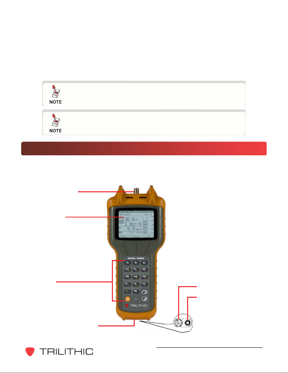
Identify Components
The Model Three’s function buttons and backlit LCD display are on the front panel. The device’s
charge socket and PC interface socket are on the bottom. The RF “F” connector is on the top of
the device. The belt clip is located on the back of the device.
RF “F” connector
LCD display
with backlight
Key pad
PC interface
Charge socket
Connectors located under
rubber cover on bottom of
device
Model Three Signal Level Meter - Operation Manual
15
Page 18
Key P ad
EL
S
SPECT
6 PQR
5
O
S
TU
0
Q
BC
G
F
2 DE
X
9 YZ
8
X
__
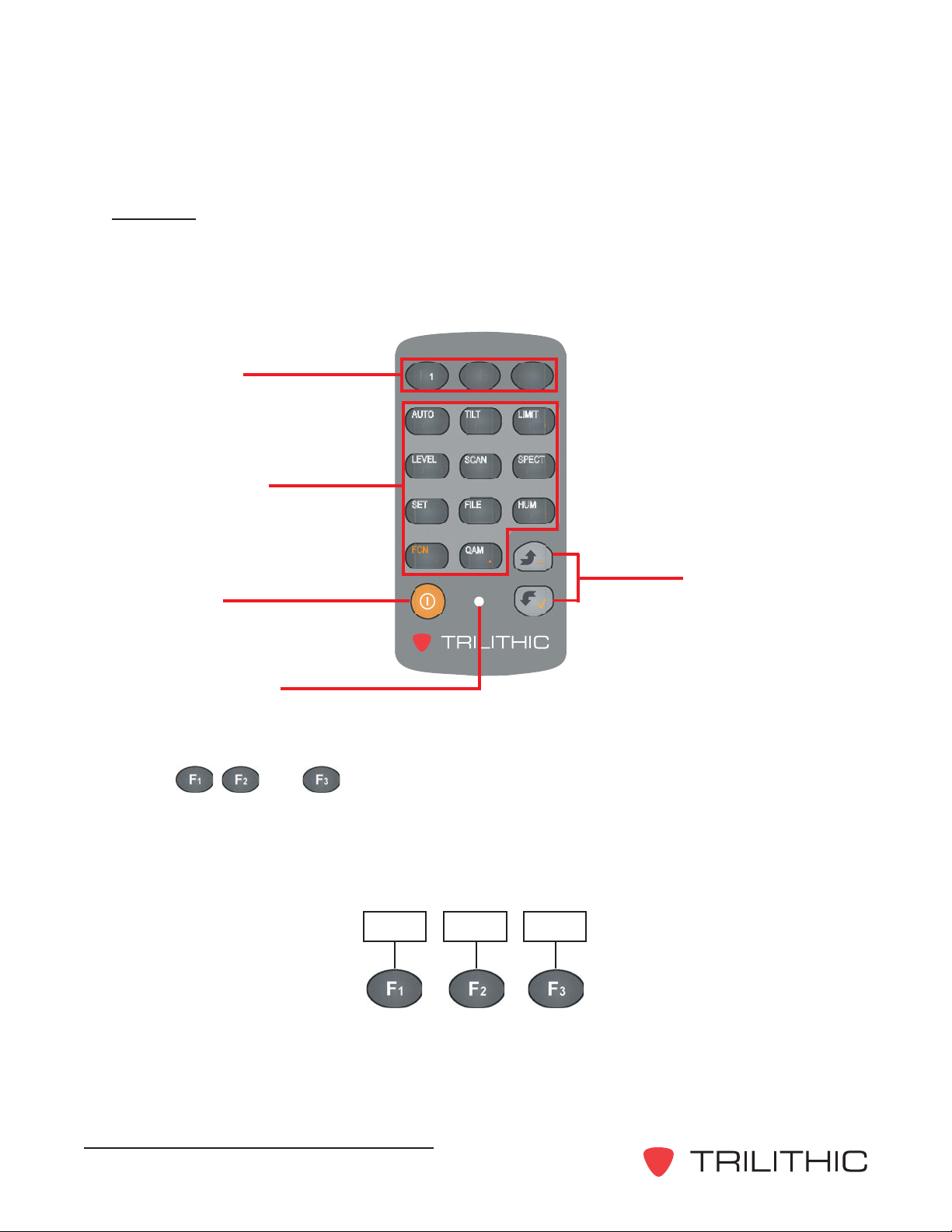
The key pad consists of the various buttons to access the Model Three’s functions. There are
eleven function buttons, two arrow buttons (up and down), the power on/off button, and three
“soft buttons” that enable you to perform functions shown on the display .
MODEL THREE
Soft Buttons
1
F
2
F
3
F
AUTO
1 ABC
LEVEL
4 JKL
4 JKL
TILT
A
SCAN
2 DEF
5 MNO
MN
LIMIT
3 GHI
SPECT
6 PQR
I3
1 1 Primary and
Secondary Function
SET
7 STU
7 S
FILE
8 VWX
VW
HUM
9 YZ*
Buttons
FCN
QAM
0
.
__
Arrow Buttons
ON / OFF
Button
Charge Indicator
Soft Buttons
The , , and keys are used to access various functions within the display
menus. On specific displays, three boxes appear at the bottom of the display . These
boxes correspond to the three soft keys and provide additional commands such as
ENTER, EXIT , SCALE, REF, movement arrows, etc. (see the individual function displays
for more information).
FREQ MAX
T
Model Three Signal Level Meter - Operation Manual
16
Page 19
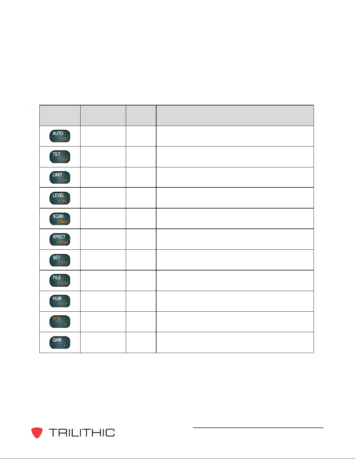
Function Buttons
The following is a list of the function buttons:
Key Function # Purpose
AUTO 1 Enter Auto test mode
TILT 2 Enter Tilt measurement mode
LIMIT 3 Enter Limit test mode
LEVEL 4
SCAN 5 Enter Channel Scanning mode
SPECT 6 Enter Frequency Spectrum scanning mode
SET 7 Use for Fast Setup or Main Setup menu
FILE 8 Save or recall measurement files
HUM 9 Enter Hum measurement mode
Enter single channel / frequency measurement
mode
FCN 0
QAM . Enter QAM measurement mode
Put the key p ad into alphanumeric mode for
entering numbers or letters
Model Three Signal Level Meter - Operation Manual
17
Page 20
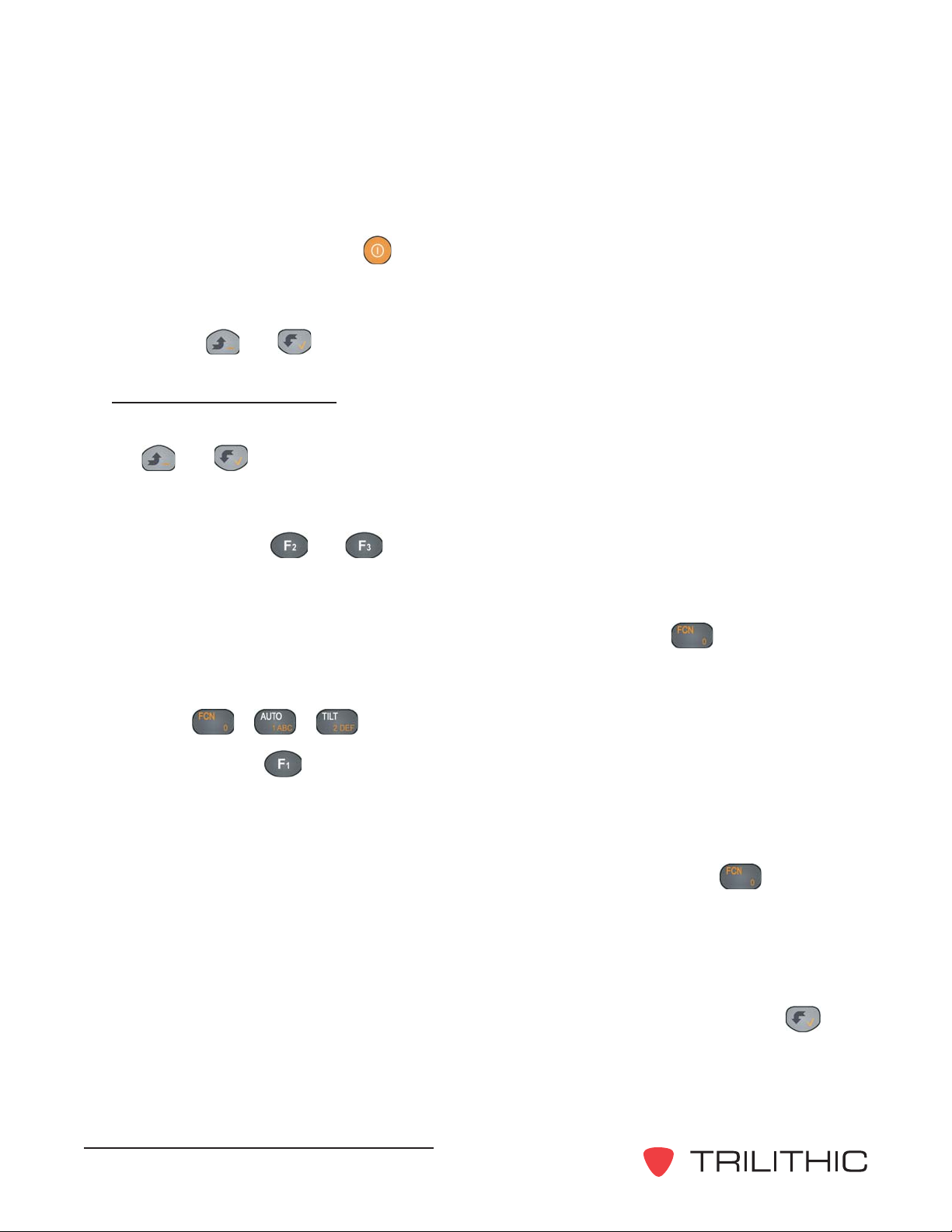
Power ON / OFF
Use the POWER ON / OFF key to turn the device on and off.
Arrow Buttons
Use the and keys to change values within a function display .
Navigating Functions
Several methods are used to navigate the Model Three’s functions. For some procedures, use
the and keys to make changes within a specific screen such as to increase or
decrease values.
T o scroll through a specific display’s menu topics, you generally use the designated sof t
buttons (usually the and keys).
Entering Numeric Values
Within several displays, you must enter numeric values. Press the key to put the key
pad in its secondary function mode, then press the number buttons to enter the desired
value. For example, to enter the number 12:
Press + +
Then press the (ENTER) key to enter the value into the Model Three.
Entering Alphanumeric Characters
Similarly , you must enter alphanumeric data on several screens, such as file names,
Channel labels, and Auto test program names. As before, you press the key to put
the key pad into its secondary function mode, then press the buttons to enter the desired
value. When you press a button in function mode, the first entry is the number associated
with the button, after which you press the same button repeatedly to scroll through the
letters associated with the button. T o enter a second letter or number using a dif ferent
button, you can go directly to the second button for entry . If you want to enter a second letter
or number using the same button as the preceding character, you must press the key
to shift the Model Three control to a new number or letter .
Model Three Signal Level Meter - Operation Manual
18
Page 21
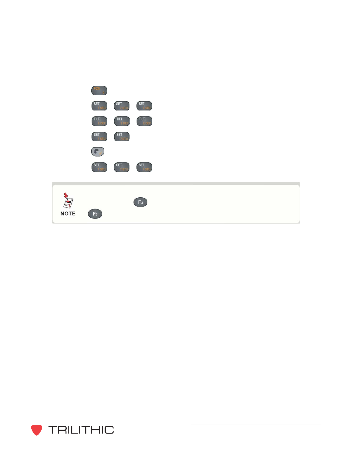
For example, to enter “TEST” in the Name field, do the following:
1. Press to switch to function mode.
2. Press + + to enter “T” in the field.
3. Press
+ + to enter “E” in the field.
4. Press + to enter “S” in the field
5. Press
to shift to a new entry with the same key .
6. Press + + to enter “T” in the field.
If you make an error when entering a number or a name, you
can press the key to go back and then re-enter it. Press the
key to escape from the operation.
Model Three Signal Level Meter - Operation Manual
19
Page 22
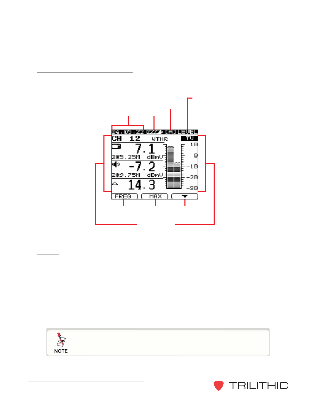
Display Screen Description
Each display contains the following sections or features.
User
plan
Time
F1 F2 F3
Time - Displays the device’s time based on time set up parameter , see Chapter 4: Setup,
General, Date and Time.
Battery
Main display
screen
Display
indicator
Battery charge - Shows the approximate percentage of remaining battery charge. Flashes
when the charge drops below 10%.
User Plan - Indicates the selected user channel plan.
Display Indicator - Indicates which function is being used.
Main Display Screen - Displays the parameters and graphs of the selected function.
F1, F2, F3 - Indicates the function of the soft buttons in the selected Model Three mode.
The soft buttons vary from function to function on the meter;
see the Soft Buttons section earlier in this chapter.
Model Three Signal Level Meter - Operation Manual
20
Page 23
Battery Charging
The Model Three has a built-in 1 1.1 V / 1.4 AH Li-Ion battery . When fully charged, it can be used
for five hours. When the battery charge drops below 10%, the battery symbol flashes in the
information line at the top of the display screen. If the charge drops below 5%, the Model Three
shuts off automatically to protect the battery . Y ou cannot turn the Model Three on again until you
recharge the battery .
T o charge the Model Three’ s battery , connect the battery charger to the charge socket on the
bottom of the Model Three (see Chapter 3: Walkthrough ,
charger into an AC outlet.
The battery MUST be charged with the Trilithic charge cube
provided with the Model Three. Using any other charge cube
may damage the battery.
While charging, the charge indicator on the front panel of the Model Three will be RED. A full
charge will be achieved in less than three hours, and will be indicated as such by a GREEN
charge indicator.
Identify Components) and plug the
The charging status may be observed by turning the Model Three ON and then OFF while the
charger is connected. The charging display will be seen with a charging curve and an
approximate percentage of charge, with the elapsed charging time.
The Model Three may be operated while the batteries are charging.
Model Three Signal Level Meter - Operation Manual
21
Page 24

THIS PAGE LEFT INTENTIONALLY BLANK
Model Three Signal Level Meter - Operation Manual
22
Page 25
Chapter 4
4. Setup
Overview
When you first press the (POWER) key , the Model Three briefly displays the S tart-Up screen,
then displays the Level screen.
The Model Three battery may need charging prior to first use,
see Chapter 3: Walkthrough, Battery Charging.
Before using the Model Three, you need to perform some setup procedures from the following
areas:
• Information (general information about your Model Three and the status of user settings)
• General (backlight time, contrast, shutdown time, temperature units, and date and time)
• Measurement (signal level units, single frequency setup, limit setup, transmission, voltage)
• Channel plan (select, learn, and edit the user plan, channel number display , tilt/favorite list)
Model Three ToolBox Software may also be used to set up the
Model Three. See the Model Three ToolBox Operation Manual
for more information.
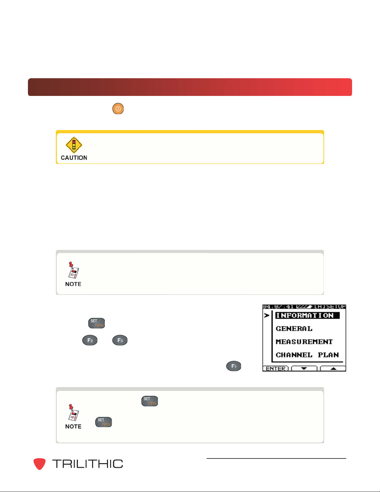
T o enter the setup display , do the following:
1. Press the key twice to display the main Setup menu.
2. Use the and keys to scroll through the main Setup
menu.
3. When the desired command is highlighted, press the
(ENTER) key to select the display .
Pressing the key once activates the Fast Setup mode to
display setup parameters for the current mode. Pressing the
key twice always displays the main Setup menu; see
Chapter 5: Basic Operation, Fast Setup.
Model Three Signal Level Meter - Operation Manual
23
Page 26
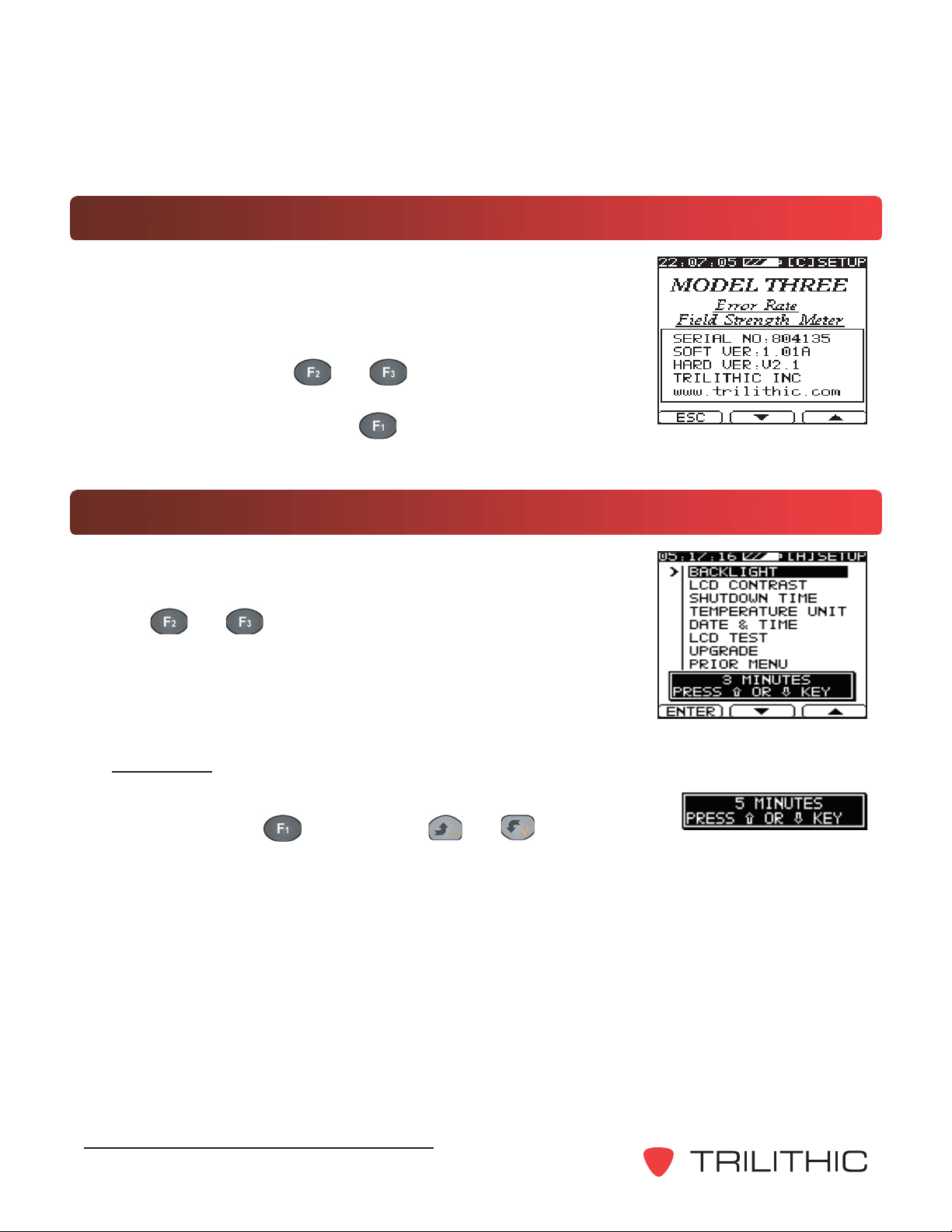
Information
The Information display windows contain useful information regarding
your Model Three.
The first screen of information shows the device’s serial number ,
firmware version, hardware version, and the company’s web
address. Y ou can use the
information screens to see more information about the Model Three,
including user settings. Press the (ESCAPE) key to return to
the main Setup menu.
and keys to scroll through other
General
Use the General menu screen to set the operational parameters of
your device.
Use the and keys to scroll through the command choices to
the desired parameter .
Backlight
This selection determines the backlighting time on the Model Three
display . Press the key (or use the and keys) to
change the backlighting time. The selected time is displayed in the
window near the bottom of the display screen. Y ou can select ON (backlighting is always on),
OFF (backlighting is always off), or 3, 5, 10, or 30 minutes (activates the backlight for the
selected number of minutes, then turns it off to save power).
Model Three Signal Level Meter - Operation Manual
24
Page 27

LCD Contrast
This selection determines the LCD contrast on the Model Three
display . Press the
to brighten.
All signal levels below -40 dBmV (+20 dB
lighter shade digits in all measurement modes to indicate they
are low signal levels.
key to darken the contrast and the key
μμ
V) are displayed with
μ
μμ
Shutdown Time
This selection sets the automatic shutdown timer . Press the
key (or use the and keys) to change the shutdown time.
The selected time is displayed in the window near the bottom of the
display screen. Y ou can select ON (always on until manually turned
off), or 3, 5, 10, or 30 minutes (the Model Three shuts itself off
when there has been no Model Three activity for the selected time
interval).
A caution screen appears 20 seconds prior to automatic
shutdown as shown below . This screen counts down the
remaining time until shutdown and displays the shutdown time
setting.
Press any key to reset the shutdown time to its current setting for
continued operation, or press the and keys to change
the shutdown time setting.
Temperature Unit
This selection specifies the temperature units used by the Model
Three. The selected temperature units are displayed in the window
near the bottom of the display screen. Press the key or press
the and keys to select Fahrenheit or Centigrade.
Model Three Signal Level Meter - Operation Manual
25
Page 28

Date and Time
This selection sets the date and time. Press the key to enter
the date and time screen.
Do the following to enter the date and time:
1. Press the key to perform alphanumeric entries. The current date disappears
from the field. Enter the date in the date order displayed to the left of the field.
2. When you are satisfied with your entry , press the key again to log the date in the
Model Three’s memory , then press the key to switch to the time field.
3. Press the key to switch the Model Three to the numeric function. The current time
disappears from the field. Enter the time (in 24-hour format). If you make a mistake
while entering the time, you can press the key to back up.
Some tips for entering dates and times:
• The Model Three automatically assigns the first two digits of the year (20), so you only
need to enter the last two digits of the year .
• Y ou may change the order of the date between Y/M/D, D/M/Y, and M/D/Y by pressing
the and keys from within the date field.
• If you make a mistake while entering a date or time, you can press the key to back
up or press the key to restore the date or time in the field.
The desired sequence for the Month, Day, and Y ear should be
set before any files are saved in the Model Three. If the date
sequence is changed after storing files, the date information for
those files will not be correct.
Model Three Signal Level Meter - Operation Manual
26
Page 29

LCD Test
This selection tests the LCD display . When you press the key repeatedly, the Model
Three display advances through four patterns to test the LCD, then returns to the menu. The
patterns are all black, all white, vertical stripes, and checkerboard. Each pattern remains on
the screen until you press the key to go to the next pattern.
Upgrade
Use this function to enter the authorization code to upgrade a Model Three to include the
Constellation diagram feature.
Contact T rilithic to obtain an authorization code, then do the following:
1. Press the key twice to go to the main Setup menu.
2. Use the and keys to select GENERAL and press the key.
3. Use the and keys to select UPGRADE and press the key.
4. Press function for alpha/numeric entry and enter the 12-digit authorization code and
press the key .
The Model Three will confirm correct entry of the code. Y our Model Three now includes the
Constellation diagram feature.
Prior Menu
Press the key to return to the main Setup menu.
Model Three Signal Level Meter - Operation Manual
27
Page 30

Measurement
Use the Measurements menu screen to set the measurement
parameters of your device. Use the
through the command choices.
and keys to scroll
Transmission
Use this selection to enable the transmission mode.
Press the (ENTER) key, or press the and keys to
enable the Transmission mode. The selected transmission state ON
or OFF is displayed in the window near the bottom of the display
screen. Use this parameter to test for transmission characteristics
and loss of in-between connections in your CA TV system (see
Chapter 6: Advanced Operation, Transmission Characteristic
Test).
Level Units
Use this selection to set the signal level units for the Model Three.
The selected signal level units are displayed in the window near the
bottom of the display screen. Press the key or press the
and keys to switch between dBmV, dB
Model Three Signal Level Meter - Operation Manual
28
μμ
μV, or dBmW.
μμ
Page 31

Single Frequency Setup
Press the key to enter the Single Frequency setup menu.
Use this menu to set the frequency steps for the frequency display
mode.
T o select an item from the Single Frequency setup menu, use the
and keys to scroll to the selection.
FREQ TUNING STEP - Select the meter’s internal step values by pressing the key, or
press the and keys. The steps can be either 10 MHz, 1 MHz, 100 kHz, 10 kHz, or
by Channel.
PRIOR MENU - Press the key to return to the previous menu.
Model Three Signal Level Meter - Operation Manual
29
Page 32

Limit Setup
Press the key to enter the Scan setup menu. Use this menu
to set Scan parameters, including test limits.
T o select an item from the Scan setup menu, use the
and
keys to scroll to the selection.
DISPLA Y LIMITS - Press the key, or press the and keys to select or deselect
viewable Limits in Scan mode. When Display Limits is activated, the test limit settings for
Minimum Video and Maximum Video can be seen on the display during channel scanning
(see Chapter 5: Basic Operation, Channel Spectrum Scanning).
EDIT LIMITS - Press the key to enter the Edit Limits menu.
All parameters used in a Limit test may be set in this menu (see
Chapter 5: Basic Operation, Limit Testing).
Use the and keys to scroll to each limit p arameter.
Select from the following:
Type Limit
Minimum Video Level -20 to 59 dBmV (40 to 119 dBμV)
Maximum Video L evel -19 to 60 dBmV (41 to 120 dBμV)
Maximum Δ Video
Minimum Video / Audio Difference 0 to 15 dB
Maximum Video / Audio Difference 5 to 30 dB
Maximum Δ Adjacent 0 to 20 dB
24 Hour Video Deviation 0 to 20 dB
Model Three Signal Level Meter - Operation Manual
30
2 to 30 dB
Page 33

A check mark appears next to each enabled limit parameter . Press the (ENTER) key to
enable or disable a limit parameter . Disabled limit parameters (indicated with an “X”) are not
tested during a Limit test.
Press the
also press the key , enter numeric data, and then press the
key to change a limit.
Y ou may scroll to SET LIMIT DEF AUL TS and press the key
to return all limits to their standard settings.
Once you have set the levels for each parameter , scroll to SA VE
AND EXIT and press the key to return to the previous
screen.
MARKER - Use this selection to switch between channel and frequency indicators for markers
in the Scan mode. Use the (ENTER) key, or press the and keys to change the
marker.
PRIOR MENU - Press the key to return to the previous menu.
and keys to change each limit value. You may
Reset Max Hold
Use this selection to reset the maximum hold value when using Max hold in Spectrum mode.
Press the (ENTER) key to reset the S pectrum mode dat a.
Voltage
Press the key to enter the Volt age display . Use this function to view battery and trunk
voltage measurements.
The Model Three is equipped with a built-in voltmeter that can be
used to troubleshoot problems with power supplies or power
drops. The Model Three accommodates AC or DC voltages up
to 100 Volt s.
The Volt age screen displays two bar graphs.
The top bar graph indicates the battery charge of your Model
Three. This approximate charge level and the battery voltage are
also displayed numerically . As you use the device, you can access this screen to check the
remaining battery power .
Model Three Signal Level Meter - Operation Manual
31
Page 34

When the battery charge drops below 10%, the battery symbol flashes in the information line at
the top of the display screen. If the charge drops below 5%, the Model Three shuts off
automatically to protect the battery (see Chapter 3: Walkthrough, Battery Charging).
The lower bar graph indicates the AC or DC volt age of the system’s trunk.
The Model Three automatically detects the presence of an AC or DC voltage and displays the
measurement graphically and numerically .
The voltmeter specifications are:
Type Specification
Input Range 10 to 100 VDC, 10 to 100 VAC
Resolution 0.1 V
Accuracy
± 2.0 V
Hum Frequency
Use this selection to set the Band Pass Filter frequencies used
during the Hum measurement. Press the key , or press the
and keys to switch between 50 Hz and 60 Hz. The
selected frequency is shown in the window near the bottom of the
display screen.
When 50 Hz is selected, 50 and 100 Hz Band Pass Filters are
enabled in Hum measurement. When 60 Hz is selected, 60 and
120 Hz Band Pass Filters are enabled in Hum measurement.
Prior Menu
Press the key to return to the main Setup menu.
Model Three Signal Level Meter - Operation Manual
32
Page 35

Channel Plan
Use the Channel Plan menu screen to select, learn, and edit up to four channel plans for the
device. Use the
and keys to scroll through the command choices.
Select User Plan
Use this selection to set the active user plan. Y ou can have up to
four user-defined channel plans (A-D) on the Model Three. Use
the (ENTER) key , or press the and keys to change
the selected user plan.
Channel Numbers
Use this selection to choose the channel identifier in the Model
Three. Use the (ENTER) key, or press the and keys
to select between St andard or EIA channel numbering.
Learn User Plan
Use this selection to learn a channel plan (for the selected user plan) from your cable system.
Whenever you learn a new Channel Plan, the previously edited
parameters are overwritten by the new plan, and all files and
Auto test programs that were saved for the previous plan are
deleted.
Press the key to learn a channel plan.
Model Three Signal Level Meter - Operation Manual
33
Page 36

A prompt appears to instruct you to connect the CATV cable to
the Model Three.
A list of eight base Channel Plans is displayed. Use the and
keys to scroll through the list to the desired base plan. With
the CA TV cable connected, press the key .
The learn channel plan settings are displayed. Use the and
keys to scroll through the settings. Use the (ENTER)
key , or press the and keys to change the channel plan
settings.
If Digital Channels are enabled for learning the user plan, all
active digital channels will be set to the parameters selected on
the list.
If a Channel Plan is learned with less than 15 active channels
found (or the cable is not connected to the Model Three), all
channels in the plan are enabled.
Model Three Signal Level Meter - Operation Manual
34
Page 37

Once you have completed making changes to the channel plan
settings, highlight DONE and use the key to search for all
active channels in your system. A progress bar at the bottom of
the screen indicates search progress.
Once the search is completed, the Model Three displays a
prompt indicating the new Channel Plan is being saved. This
learned Channel Plan (for the selected User Plan) has all active
channels enabled . Analog channels with levels less than -10
dBmV (50 dBμV) and Digital Channels with levels less than -17 dBmV (43 dBμV) are not
enabled.
After learning a Channel Plan, the Model Three returns to the Level measurement mode. Y ou
may then modify the various parameters in the plan.
T o return to the Channel Plan Setup menu to edit your User Plan, press the key twice to
return to the main Setup menu, use the and keys to scroll to the Channel Plan
selection, press the (ENTER) key to display the Channel Plan menu and then use the
and keys to scroll to Edit User Plan.
Edit User Plan
Once you have learned a Channel Plan, you can edit the plan.
Whenever you edit a Channel Plan, all files and Auto test
programs that were saved for the User Plan prior to editing are
deleted.
Press the key to display the selected User plan for editing.
Model Three Signal Level Meter - Operation Manual
35
Page 38

Within the Edit User Plan display , use the and keys to
scroll through the list of channels. All enabled channels have a
check mark under ENA. When the channel you wish to modify is
highlighted, press the (ENTER) key . The selected Channel
Setup screen appears.
T o select the channel’ s parameters, use the and keys to
scroll up and down the list. There are different methods for
modifying each parameter .
When using FCN to make an alphanumeric entry, remember to
press the (ENTER) key after you have made an entry to
store the new data (see Entering Alphanumeric Characters in
Chapter 3: Walkthrough, Identify Components, Navigating
Functions).
EIA Number - Press the key to switch to alphanumeric entry mode, then enter the
desired EIA number for the channel. When you are satisfied with your entry , press the
(ENTER) key to store the change.
Standard Number - Press the key to switch to alphanumeric entry mode, then enter the
desired standard number for the channel. Press the (ENTER) key to store the change.
Channel Label - Press the key to switch to alphanumeric entry mode, then enter the
desired label (up to 5 characters) for this channel. Press the (ENTER) key to store the
channel label.
Active Status - Press the key to switch between ENA (enabled) and DIS (disabled).
Enabling a channel adds it to the selected User Channel Plan. Disabling a channel removes it
from the User Plan.
Type - Use the key to toggle between the channel types; TV, SIGL or DIGI.
The rest of the parameters in the edit list are affected by which
type of channel is selected.
Model Three Signal Level Meter - Operation Manual
36
Page 39

TV - Audio and Video carriers (parameters: Frequency (Video), Audio Offset)
SIGL - Single Frequency Channels (parameters: Center Frequency , Measure BW)
DIGI - Digital Channels (parameters: Center Frequency , Measure BW)
Frequency - Press the key to switch to Numeric Entry mode and enter the desired
frequency (Video Frequency for TV type channels or Center Frequency for DIGI and SIGL type
channels). Once the desired modification is made, press the key to store the change.
The new frequency you enter should always be less than
1000 MHz.
Aud Offset - Press the key to switch to Numeric Entry mode and enter the positive offset
of the audio frequency from the video carrier. Press the (ENTER) key to store the
change (this parameter appears for TV type only).
Measure BW - Press the key to switch to Numeric Entry mode and enter the
measurement bandwidth for this channel. Press the (ENTER) key to store the change
(this parameter appears for DIGI and SIGL types only).
Mode T ype - Press the (ENTER) key to select the modulation type (this parameter
appears for DIGI type only).
SR - Press the key to switch to Numeric Entry mode and enter the Symbol Rate (MS/s)
for the channel. Press the (ENTER) key to store the change (this parameter appears for
DIGI type only).
Model Three Signal Level Meter - Operation Manual
37
Page 40

When you are satisfied with your entries, highlight SA VE AND EXIT and press the
(ENTER) key to return to the Edit User Plan screen.
Adding a Channel: A channel may be added while in the Edit User Plan list of channels by
pressing the key . A Channel Edit screen appears for the new channel with the next
available channel number assigned. This channel number may be changed, but an existing
number in the plan (enabled or not) may not be used. Other parameters on the new Channel
Edit screen should be set, including frequency , which has a default setting of 55.25 MHz.
When finished, select SA VE AND EXIT and press the
(ENTER) key to return to the Edit
User Plan screen.
All channels, including a new channel, appear in the Channel Plan according to frequency—not
channel number.
Deleting a Channel: A channel may be entirely deleted while in the Edit User Plan list of
channels by pressing the key . If a channel is deleted, it will not be available to enable
later, and it will not be scanned in the Full S pectrum Scan mode. It is recommended that a
channel be disabled instead of deleted from the plan.
When you have completed your changes to all channels that require edit in the User Plan,
press the key to save the modifications and return to the main Setup menu.
All edits are temporarily stored until you exit the Edit User Plan
screen. Do not turn off the Model Three before exiting the Edit
User Plan screen, or the changes will not be saved.
Model Three Signal Level Meter - Operation Manual
38
Page 41

Tilt/Level List
This feature lets you select up to twelve favorite channels. These channels are also used when
making the Tilt measurement.
You must select at least four channels to make the Tilt
measurement. The Model Three uses the highest and lowest
frequencies when making the measurement.
Press the (ENTER) key from the T ilt/Level List selection on
the Channel Plan Setup menu to enter the Tilt Setup screen.
T o add a channel to the Favorites list, use the and keys to scroll the list of channels
in the selected User Plan. When the desired channel is highlighted, press the key . A
check mark appears next to the channel under the Tilt column, and the channel number is
placed in the Favorites column at the bottom of the display . As you add channels, the
Favorites list arranges them in order of their frequency . For example, even if you selected
Channel 14 first, as you add Channels 4 and 6, these channels go to the top of the list.
Use the and keys to scroll through the User Plan list
one page (6 channels) at a time.
T o delete a T ilt/Favorite channel, scroll to the channel and press the key . The channel is
removed from the list.
Once you have selected from four to twelve favorite channels, press the key to save the
information and return to the main Setup menu.
Model Three Signal Level Meter - Operation Manual
39
Page 42

Load Defaults
Press the (ENTER) key to load the factory default settings for the Model Three and then
display the Level screen. This will not change the User Channel plan.
Prior Menu
Press the (ENTER) key to return to the main Setup menu.
Model Three Signal Level Meter - Operation Manual
40
Page 43

Chapter 5
5. Basic Operation
Once you have set up the Model Three’s parameters, you are ready to operate the device.
There are a number of tests you can perform with the Model Three:
• Single channel level tests
• Frequency mode
• Channel scans
• Limit tests
• Frequency scanning (spectrum)
• Hum measurement
• QAM measurement
• Tilt and favorite channel levels
The Model Three displays readings down to -50 dBmV (+10
μμ
dB
μ
V). All signal levels that are below -40 dBmV (+20 dB
μμ
displayed with lighter shade digits in all measurement modes to
indicate they are low signal levels.
μμ
μ
V) are
μμ
Fast Setup
The Model Three features a Fast Setup function for each measurement mode. The specific setup
menu for each mode can be accessed directly by pressing the key once while in the
Measurement mode. This makes it unnecessary to go back to the main Setup menu and look for
nested sub-menus. This allows the operator to quickly make changes in the settings and return to
Measurement mode with no wasted time.
Pressing the key twice always displays the main Setup
menu.
Model Three Signal Level Meter - Operation Manual
41
Page 44

Single Channel Level Testing
When set to the single channel level test, the Model Three displays bar graphs of the video and
audio carriers as well as numeric readouts of the carrier amplitudes and V/A difference. The
Model Three can also display a spectrum scan of the selected channel showing the amplitudes of
the video and audio carriers and undesired signals that may be present, such as intermodulation.
T o access the Level screen, press the key.
The Model Three displays the Level screen for the last channel it was on before being turned off.
TV Channels
When measuring a TV type channel with audio and video carriers (see Chapter 4: Setup,
Channel Plan, Edit User Plan), the left column of the bar graph represents the video carrier
while the right column displays the audio carrier. The V/A Δ is displayed below the video and
audio carriers.
Channel label
Channel
Video carrier
Audio carrier
V/A Δ
T o change the channel, use the and keys or press the key, enter the desired
channel number, and press the (ENTER) key .
The Level screen displays a scale that you can adjust by pressing the (DOWN) key so
that the functions of the and keys become SCALE and REF. Press the
(SCALE) key to vary the graduation of the scale according to a 1, 2, 5, and 10 dB per division
scale.
F1 F2 F3
User plan
Channel type
Model Three Signal Level Meter - Operation Manual
42
Page 45

For example, to change the display graph from a 10 dB scale to a
5 dB scale, press the key three times to cycle through the
steps.
Y ou may also change the reference level of the graph. Press the
(REF) key and then press the and keys to increase
or decrease the reference by one digit at a time.
Press the (UP) key to return to the original Level screen so
that the functions of the and keys become FREQ and
MAX.
The amplitude of the graph changes as you change the scale
and reference so that it continues to indicate the correct level.
You must press the (UP) key to return to the original Level
screen for the and keys to change channels (instead of
reference) again.
The Model T wo digital readout can be set to display a LIVE, MAX, or
ΔΔ
Δ P-P signal level as an
ΔΔ
aid to troubleshooting. Press the key to select the desired display mode as described
below:
• LIVE is the normal operating mode whereby the digital display indicates the current
value of the input signal.
• In the MAX mode, the digital display indicates the maximum level of the input signal. In
this mode, an M is displayed after the digital reading.
• In the Δ P-P mode, the digital display indicates the variation in the input signal level. In
this mode, a
ΔΔ
Δ is displayed after the digital reading.
ΔΔ
The analog bar graphs for Audio and V ideo continue to indicate the LIVE level in all modes,
while the wavy line at the top of each bar indicates the maximum level of the Audio and V ideo
signals.
Model Three Signal Level Meter - Operation Manual
43
Page 46

Single Channel Spectrum
The Model Three can scan the spectrum of the designated
channel automatically . This function is particularly useful for CA TV
measurements. To scan the channel spectrum, press the
key again. The Model Three displays the spectrum screen and
scans the channel for data, which it then graphs on the screen.
The Center Frequency and Channel Number are displayed, along
with the Marker Frequency and Level. Use the
to move the Marker Frequency to any position in the channel
spectrum.
A Δ Marker function can also be used to check the distance (in
MHz) and amplitude difference between any 2 points in the
displayed spectrum. First, use the and keys to move the
marker to a reference position, then press the (Δ MKR) key .
The and keys now move the second marker from the
reference position, and the Δ Frequency and Δ Level are
displayed. Press the (MARK) key to return to the normal
single-marker spectrum display .
Use the (AUTO) key to automatically set a scale and reference for the displayed
spectrum graph. Y ou may set the Scale and Reference manually by pressing the
(DOWN) key and using the and keys for Scale and Reference as described for the
preceding Level display mode.
The spectrum display can also use an A verage detector instead of Peak detector by pressing
and keys
the (DOWN) key and using the key to select A VG. This is most useful for digital
channels to see a quick scan of the average power for frequencies across the channel
bandwidth.
Model Three Signal Level Meter - Operation Manual
44
Page 47

Single Frequency Channels
Y ou can use the Model Three to measure a Single Frequency level over a specified bandwidth.
T o do this, first set the Model Three’ s channel type to SIGL or single frequency channel (see
Chapter 4: Setup,
The level for the signal is displayed along with an F to indicate
Single Frequency mode. Also displayed are
to indicate the distance and amplitude difference between the
center frequency and the highest peak of the signal in the
bandwidth.
T o scan the channel spectrum, press the key again.
Channel Plan, Edit User Plan).
While in Level mode, you can use Fast Setup to go directly to
the setup parameters for the current channel.
ΔΔ
Δ FREQ and
ΔΔ
ΔΔ
Δ AMP
ΔΔ
With a Single Frequency Channel, the Level (Live, Max,
Scale, Reference, Auto, Marker ,
used as described for TV Channels.
ΔΔ
Δ
Marker, and Average may be
ΔΔ
Model Three Signal Level Meter - Operation Manual
ΔΔ
Δ
p-p),
ΔΔ
45
Page 48

Digital Channels
Y ou can use the Model Three to measure the average power of a digital channel (QAM,
QPSK, or COFDM) according to the configured bandwidth. To do this, first set the Model
Three’s channel type to DIGI (see Chapter 4: Setup,
The level for the signal is displayed, along with a P to indicate the
power level over the specified bandwidth for DIGI mode.
Channel parameters are also displayed, including Center
Frequency , Bandwidth, Modulation T ype, and Symbol Rate.
Channel Plan, Edit User Plan).
T o scan the channel spectrum, press the
With a Digital Channel, the Scale, Reference, Auto, Marker ,
Marker, and Average may be used as described for TV
Channels.
The Marker level indicated for a DIGI signal in the channel spectrum mode is only the level at
the marker frequency and not the total power for the channel bandwidth. Y ou can return to the
single-channel level mode (press the key again) to read the total power of the set
bandwidth.
key again.
ΔΔ
Δ
ΔΔ
Model Three Signal Level Meter - Operation Manual
46
Page 49

Frequency Mode
When set to the Frequency Mode, the Model Three displays the
frequency and level for the desired channel. T o access this screen,
press the key .
The Single Channel Level screen is displayed.
Now, press the
This toggles the Model Three so that it displays the Frequency screen
for the channel designated in the Single Channel Level screen.
If the channel is a TV type channel with audio and video carriers, the Model Three is tuned to the
audio frequency . If the channel is a DIGI type channel, the Model Three is tuned to the center
frequency . The signal level and peak level are displayed.
T o change the frequency that is being measured, press the and keys. The frequency
moves in increments set in the Single Frequency Setup menu.
(FREQ) key .
While in Frequency mode, you can use Fast Setup (press the
key once) to go directly to the Single Frequency Setup
frequency steps.
By pressing FCN, you can enter the desired frequency. T o
finish, press the (ENTER) key.
The level display can be set to display a LIVE or
key .
The Scale and Reference shown on the Frequency screen can be adjusted by pressing the
(DOWN) key so that the functions of the and keys become SCALE and REF. Press the
(SCALE) key to vary the graduation of the scale by 1, 2, 5, and 10 dB per division. Press the
(REF) key and then press the and keys to increase or decrease the reference.
Press the (UP) key to return to the original soft key functions of CHAN and
and keys change frequency (instead of reference).
ΔΔ
Δ P-P (variation) signal level by pressing the
ΔΔ
ΔΔ
Δ P-P so the
ΔΔ
Model Three Signal Level Meter - Operation Manual
47
Page 50

Channel Scanning
The Model Three is designed to display the full span of all channels including video and audio
carriers, or digital channels in your system. This function provides a quick check of your system’s
overall flatness and amplitude.
The Model Three can also be set to display the channels at reduced frequency spans. Amplitude
limits can be imposed on the display , while a convenient Marker enables you to zoom in on any
suspect channels.
T o enter the Channel Scanning screen, press the key. The
currently selected User Channel Plan measurement data is displayed
in a graph with a viewing range of 126 channels (this can be
extended to 170 by adjusting the Scan Marker).
The Audio levels are shown graphically with a light shade, while
Video levels are shown darker . Digital channels (DIGI) and Single
Frequency channels (SNGL) that do not have separate audio and
video components are shown as all dark.
The Model Three also displays the marker (by channel or frequency) and its video, audio, and V/A
Δ levels along with the Low (starting) and High (ending) frequencies.
When entering Scan mode, the marker is positioned on the last channel used in Level mode. This
makes it easy to quickly view a selected channel within the channel plan.
T o change the marker channel, press the
and enter the channel (or frequency if selected), then press the key to move the marker to the
desired location.
The marker may be changed from channel number to
frequency: Press the key once for Fast Setup, select
Marker, and press the key to change the marker indication.
and keys. You can also press the key
Model Three Signal Level Meter - Operation Manual
48
Page 51

Y ou can zoom in on the marker position by pressing the key .
The Model Three supports 5 levels of magnification (1x, 2x, 3x, 4x,
and 5x), or scan of the full channel plan.
The minimum span (5x) shows 25 channels of data.
T o return to the original zoom level, keep pressing the
cycle through the zoom magnifications.
Y ou can stop the scanning process so you can study the graph
without losing the current data. In the Channel Scan screen, simply press the
The scanning marker stops moving. To resume scanning, press the
T o set the reference level and the scale automatically , press the (AUTO) key . The Model
Three selects the optimal scope for your system.
The Scale and Reference shown on the Channel Scan screen can also be adjusted manually by
pressing the (DOWN) keys so that the functions of the and keys become Scale
and Ref. Press the (SCALE) key to vary the graduation of the scale by 1, 2, 5, and 10 dB
per division. Press the (REF) key, then press the and keys to increase or
decrease the reference. Press the (UP) key to return to the original soft key functions of Auto
and Hold.
key to
(HOLD) key .
(TRIG) key .
Display Limits
When Display Limits is set to Y es in the Scan Setup menu (see
Chapter 4: Setup, Measurement, Limit Setup), the Channel
Scan display shows the limit lines for the specified Minimum
Video level and Maximum Video level.
While in the Channel Scan mode, you can use Fast Setup (press
the key once) to go directly to the Scan Setup parameters,
including Marker type, Display Limits, and the Edit Limits
screen.
Model Three Signal Level Meter - Operation Manual
49
Page 52

Limit Testing
The Model Three can quickly perform a test of all analog channels in
the cable system to specified test limits with a single key press. The
selected User Channel Plan is tested to all enabled limit parameters
as set in the Edit Limits display from the Limit Setup menu (see
Chapter 4: Setup,
Limit test, press the key .
Channels are displayed momentarily as each channel is scanned. In
addition, a progress bar indicates the scan status.
When the Limit test is complete, a T est Result summary screen
appears to indicate the Pass or Fail status for each test parameter .
Each test that has passed has a check mark next to that parameter .
Each test that has failed has an X next to that parameter .
Measurement, Limit Setup). To perform the
The Maximum Δ Video and Maximum Δ Adjacent channel status are
determined by the results of the overall channel plan measurements.
Press the and keys to view the Minimum and Maximum
Video channels and levels. Also, if a failure has occurred for the
Maximum Δ Adjacent channel test, the adjacent channels with the
greatest variation are listed.
A digital (DIGI) type channel is measured during the Limit test
but is not used to determine Pass or Fail for any of the tests.
The Minimum Video, Maximum Video, Minimum Δ V/A, and Maximum Δ V/A are tested for all
channels in the User Plan. If any channel fails one of these tests, the Test Result summary
indicates a failure X for that test. If all channels pass one of these tests, the Test Result summary
indicates a pass (check mark) for that test.
Model Three Signal Level Meter - Operation Manual
50
Page 53

The results for each channel from the individual channel tests can be
viewed by pressing the (LIST) key . The total number of failed
channels is shown at the top of the display , and each channel is listed
with the channel type, signal level (Video level if TV ), and a pass or
fail indication. Each channel that has passed all four individual
channel tests displays a check mark. Each channel that has failed
any of the 4 individual channel tests displays an X.
Y ou can use the and keys to scroll through the list of
channels one at a time, or use the and keys to scroll one
page (8 channels) at a time.
Press the key to look at the Limit test information for a specific
channel.
The Video level, Audio level, and Δ V/A for the selected channel are
shown at the top of the individual channel information screen. The
Limit test setup for the channel test parameters is displayed at the bottom of the screen with a
Pass or Fail indication for each parameter .
Frequency Spectrum Scanning
The Model Three can be set to display spectrum measurements with spans ranging from 2.5 to
62.5 MHz. It can also be set for a full spectrum scan of the base channel plan with sampling at
each video carrier frequency or center frequency of digital channels.
The Model Three can show spectrum data with absolute
measurements, or it can store data for comparative tests using
the TRANSMISSION feature.
TRANSMISSION mode is set up in the Measurement menu.
Since the following data is for normal (absolute) spectrum
scanning, TRANSMISSION should be set to OFF in the
MEASUREMENT menu (see Chapter 4: Setup, Measurement,
Transmission).
Model Three Signal Level Meter - Operation Manual
51
Page 54

While in the Spectrum mode, you can use Fast Setup (Press the
key once) to go directly to the Measurement Setup
parameters including Transmission.
For further information on Transmission operation, see Chapter 6: Advanced Operation,
Transmission Characteristic Test.
The following information is for normal (absolute) spectrum scanning.
T o enter the Frequency S pectrum Scanning screen, press the
key .
When the Full Spectrum scan is displayed, the S pan indicator (SP) is
displayed as PLAN_A-D (full span of selected user base plan). The
starting frequency (ST) is shown along with the marker frequency and
level.
With Full Spectrum scan, all video carrier frequencies or center
frequency of digital channels in the selected Base Channel Plan
(including those disabled for Channel Scan) are scanned.
T o move the marker frequency , press the and keys.
T o change the spectrum bandwidth, press the (SPAN) key. The
span cycles through 2.50M, 6.25M, 12.50M, 25.00M, 62.50M and
PLAN_A-D (full span).
When a span other than full span (PLAN_A-D) is selected, the
display shows the center frequency .
T o change the center frequency , press the key to place the
keypad in its numeric function. Enter the desired new center frequency and press the
(ENTER) key . If you enter an incorrect digit, do not press the key . Instead, press the
(BACK) key . Y ou can exit the procedure by pressing the (ESC) key to return to the original
center frequency .
Model Three Signal Level Meter - Operation Manual
52
Page 55

The Spectrum mode can be set to hold the maximum (peak) spectrum dat a for display . Each time
the
key is pressed, the Model Three switches between Live and Max modes. MAX appears
in the upper-right corner of the display when this mode is used. The Max hold data is retained as
long as the Model Three is on. To reset the Max hold data in Spectrum mode, you must select
RESET MAX HOLD in the Measurements Setup menu.
While in the Spectrum mode, you can use Fast Setup (press
SET once) to go directly to the Measurement Setup parameters,
including Reset Max Hold.
Y ou may wish to stop the scanning process so you can study the graph. In the S pectrum screen,
simply press the (HOLD) key . The scan marker stops moving. To resume scanning, press
the (TRIG) key .
Other functions are available by using the key to change the function of the and
keys.
Press the key to change the function of the and keys to Scale and Ref. Change
the display scale by pressing soft key the (SCALE) key . Change the reference level by
pressing soft key F2 (REF) and using the and keys to change the reference.
Press the key to change the function of the and keys
to Auto and ΔMkr. T o set the reference level and the scale
automatically , press the (AUTO) key . The Model Three selects
the optimal scope for your system.
A Δ Marker function can be used to check the distance (in MHz) and
amplitude difference between any 2 points in the displayed spectrum.
First, use the and keys to move the marker to a reference
position, then press the (ΔMKR) key . The and keys
now move the second marker from the reference position, and the Δ Frequency and Δ Level are
displayed.
Press the (MARK) key to return to the normal single-marker Spectrum display .
Press the key to change the function of the key to A V G . This permits the S pectrum
function to use an A verage mode instead of a Peak detector . This is most useful for digital
channels to see a quick scan of average power for frequencies within the selected span.
Model Three Signal Level Meter - Operation Manual
53
Page 56

Hum Measurement
The Hum measurement function is used to troubleshoot interference
that my result from a defective power supply or faulty or overloaded
power inserters. This mode includes a Low Pass Filter and 60 Hz
and 120 Hz (or 50 Hz and 100 Hz) Band Pass Filter measurements.
T o enter the Hum Measurement screen, press the key . The
currently selected (or nearest) analog channel Hum measurement is
displayed for the LPF (Low Pass Filter).
The measured channel may be changed using the
keys.
The Low Pass Filter will measure the level of frequencies from 1 to 400 Hz.
Press the key again to view the 60 Hz and 120 Hz Band Pass
Filter measurements.
The Band Pass Filter frequencies can be changed from 60 Hz and
120 Hz to 50 Hz and 100 Hz in the Measurements Setup menu.
The measured channel may be changed using the and
keys.
and
QAM Measurement
The Model Three is able to measure MER, and pre- and post-BER. It
takes an average of one second to perform the QAM measurements.
QAM Channel Measurement
T o enter the QAM Measurement screen, press the key.
Press the key to input the channel number or use the
and keys. During testing, press the (TRIG) key to
execute the power testing once. MER and BER testing will execute after power testing.
When the meter is locked on a digital channel, the Interleave Depth standard of the signal will
appear in the upper-right corner of the display .
Model Three Signal Level Meter - Operation Manual
54
Page 57

Press the (DOWN) key to use and keys to set the Scale and Reference for the
display.
Press the (DOWN) key to use the key to switch the display between pre-BER and
post-BER measurements.
In this mode, press the
center frequency , bandwidth, modulation mode, symbol rate, and other digital channel settings.
key to view the settings for the current channel. Y ou can setup
QAM Frequency Mode
The Model Three provides a frequency mode to easily view and
setup the key measurement parameters for QAM testing. Press
the (FREQ) key to display the frequency mode.
T o change the measurement frequency , press the key and
enter the new measurement frequency .
The table shown on the following page describes the menu
structure of the QAM frequency mode and the options available by
pressing the key .
Model Three Signal Level Meter - Operation Manual
55
Page 58

Menu
Number
Display Key Function
CHAN F1 Back to ch annel test mode.
RENEW F2 Refresh the measureme nt. 1
DOWN F3 Turn to Menu number 2 .
2
4
MODE F1
RATE F2
Choose Modulation mode
(16 ~ 256 QAM)
Choose Symbol Rate
(1.000 ~ 7.000 M s / sec)
UP / DOWN F3 Turn to Menu number 3 .
PRE / POST F1 Switch between Pre-BER and Post-BER.
STEP F2 Set the Frequ ency step. 3
UP / DOWN F3 Turn to Menu number 4 .
STD F1
Choose Modulation Standard
(J-83A / J83-B / J83-C )
NONE F2 None
UP F3 Back to Menu number 1.
Model Three Signal Level Meter - Operation Manual
56
Page 59

Spectrum Analyzer Display
Pressing the key a second time will display the spectrum
analyzer screen for the selected channel.
See Chapter 5: Basic Operation, Single Channel Level T esting for
complete instructions.
QAM Constellation Display (Optional)
Pressing the key a third time will display the Constellation
display for digital channels. In order to view the QAM
Constellation diagram you must have this option enabled.
The QAM Constellation display allows for a more intuitive
measurement of a digital channel’s faults.
Press the and keys to choose a quadrant to view and
press the key to refresh the constellation.
Each quadrant can be observed individually by pressing the
key to zoom in. T o zoom out, press the key .
Model Three Signal Level Meter - Operation Manual
57
Page 60

Tilt and Favorite Channel
When installing and maintaining your CA TV system, you may want to concentrate on the level of
only a few channels and the gain distribution of the transmission line.
Y ou can use the T ilt and Favorite Channel function to display and adjust the level and work status
of your system. Y ou may have up to 12 favorite channels for each User Plan. To enter the Tilt and
Favorite Channel screen, press the key .
You must have at least four channels selected for the Tilt/
Favorite display to operate.
The Tilt Setup display can be accessed directly by pressing the
(SETUP) key . See the Tilt/Level List Setup section of the Channel
Plan Setup menu (see Chapter 4: Setup, Channel Plan, Tilt/Level
List).
When 4 to 12 channels have been selected for T ilt/Favorite channels,
the Tilt screen can be displayed with a graph of the V ideo levels for
each channel.
The measured levels of the LOWEST and HIGHEST frequencies
listed in the Tilt/Favorite list are used to calculate tilt. These levels
and the tilt calculation (Δ) are displayed.
T o adjust the reference level, press the (REF) key , then press
the and keys. T o change the scale, press the
(SCALE) key .
Press (SETUP) to set the tilt channels. Use the and
keys to highlight the channels to be used in the tilt measurement and
press the (ENTER) key to select or deselect the channel. The
enabled channels display a check mark.
T o bring up the list of favorite channels, press the key again.
The Model Three displays the list of favorite channels with their Video
Carrier Levels or digital power levels and the tilt calculation.
Model Three Signal Level Meter - Operation Manual
58
Page 61

Chapter 6
6. Advanced Oper ation
Once you have a general understanding of the Model Three’s basic features, you can try the
advanced features, such as testing for transmission characteristics, auto-testing, and saving data.
Transmission Characteristic Test
The Model Three enables you to test the transmission characteristics (gain and tilt) of your CA TV
distribution system. Maintaining proper gain and tilt is a necessary step in ensuring the quality of
signals delivered to your customers.
The Model Three enables you to do this by setting a reference at a known good test point such as
the headend’s output test point or a node’s output test point. This reference can then be
compared to the transmission response at other places in the distribution system to allow proper
gain and tilt adjustments of the distribution system.
T o test the transmission characteristics, you first need to enable the T ransmission option.
From Spectrum mode, the Measurements Setup menu, including
Transmission, can be accessed quickly with Fast Setup by pressing
the key once. With Transmission selected, press the key
to switch from OFF to ON.
The Model Three asks if you want to replace the zero reference data.
T o replace the zero reference data, press the (YES) key . To
use the existing Zero Reference level, press the (NO) key . Y ou
can exit this screen by pressing the (ESC) key .
The first time you use the Model Three, you should press the
key to replace the initial Zero Reference data.
When you press the key to replace the Zero Reference data, the
Model Three prompts you to connect the device to the cable system.
Model Three Signal Level Meter - Operation Manual
59
Page 62

After you have connected the CA TV source to the Model Three, press
the (ENTER) key. The Model Three scans all video carrier
frequencies in the selected Base Channel Plan, including those
disabled for channel scan (see Chapter 4: Setup,
Channel Plan).
When the Model Three has completed the new Zero Reference scan,
a prompt appears to press the
key to start a Relative S pectrum
measurement.
Press the (ENTER) key to start the Relative S pectrum
measurement.
The Model Three displays the transmission measurement. The
reference level indicates Δ dB to show the difference between the
current Scan Level and the Zero Reference scan. In the example to
the right, a 6 dB loss is seen with the transmission measurement.
Channels in the Base Channel Plan that are not active on your
system have a transmission indication near 0 dB, because there
was no signal to be changed. A User Plan can be configured
with only active channels by deleting the unused channels (see
Chapter 4: Setup, Channel Plan, Edit User Plan.) This provides a
transmission scan with all active data.
The new Zero Reference remains in the Model Three’s nonvolatile memory even when the Model
Three is turned off. This enables you to measure the level’s relative change at a later time. T o
perform a new Transmission test at any time, confirm that TRANSMISSION is set to ON in the
Measurement Setup menu and then press the key . The Model Three performs a S pectrum
Scan and compares it to the reference data.
Press the and keys to move the marker frequency .
The Span function does NOT operate when the Model Three is
in the TRANSMISSION mode. For normal (absolute value)
Spectrum Measurements, set the TRANSMISSION selection to
OFF.
Model Three Signal Level Meter - Operation Manual
60
Page 63

Y ou may wish to stop the scanning process so you can study the transmission graph. Simply
press the (HOLD) key . The scan marker stops moving. To resume scanning, press the
(TRIG) key .
As in Spectrum mode (absolute), other functions are available by using the key to change the
function of the and keys.
Press the key to change the function of the and keys
to SCALE and REF.
Change the display scale by pressing the (SCALE) key.
Change the reference level by pressing soft key the
and using the
and keys to change the reference.
(REF) key
Press the key to change the function of the and keys
to Auto and
ΔΔ
ΔMkr. T o set the reference level and the scale
ΔΔ
automatically , press the (AUTO) key .
A Δ MARKER function can be used to check the distance (in MHz)
and amplitude difference between any two points in the displayed
transmission spectrum. First, use the and keys to move the
marker to a reference position, then press the (ΔMKR) key . The
and keys now move the second marker from the reference
position, and the Δ Frequency and Δ Level are displayed.
Press the (MARK) key to return to the normal single-marker
Transmission display .
Press the key to change the function of the key to A VG to
enable an average level reading instead of a Peak Detector reading
in the spectrum scan.
The new Zero Reference scan remains in the Model Three so you
can measure the relative change at a later time. T o perform another
Transmission test at any time, confirm that T ransmission is set to ON
and press the key . The Model Three performs a S pectrum scan
and compares it to the reference data.
If Transmission has been turned of f for absolute Spectrum measurements, you can turn it on and
press the (NO) key when asked to replace the Zero Reference data.
The Model Three then prompts you to select the key to start a relative S pectrum
measurement with the old Zero Reference data.
Model Three Signal Level Meter - Operation Manual
61
Page 64

Auto Test
The Model Three can accept user-defined testing programs to automatically perform Level,
Spectrum, Tilt (Favorite), Hum, QAM, and Limit tests in specified time increments. The Model
Three can store up to seven user programs for recall when needed. The test results are stored to
a file automatically after measurement and they can be viewed or uploaded to a PC later .
T o run or set up an Auto test, press the key . The Auto test
program directory appears.
T o create a new Auto test, press the
highlighted. If the directory has no programs, the blank selection
appears automatically .
Press the (NEW) key.
The Auto test screen for STEP 1 appears. Press the (NAME)
key for the alphanumeric entry window to appear.
Enter up to five alphanumeric characters for the program name and
press the (ENTER) key (see Entering Alphanumeric Characters
in Chapter 3: Walkthrough, Identify Component s, Navigating
Functions).
key until a blank selection is
Model Three Signal Level Meter - Operation Manual
62
Page 65

The new program name appears on the screen for STEP 1. Press
the (NEXT) key to continue.
The Auto test screen for STEP 2 appears.
Six types of tests may be performed in a program: Level, S pectrum,
Limit, Hum, QAM, and Tilt. Each enabled test has a check mark next
to it.
Use the and keys to highlight any test, then press the
(ENTER) key to enable or disable the test.
When only the desired tests are enabled with a check mark, press
the (NEXT) key to continue.
The Auto test screen for STEP 3 appears.
Y ou can change the parameters for each of the selected tests by
using the and keys to highlight the test, then press the
(ENTER) key .
The Auto test p arameter displays are described in the following
section.
Model Three Signal Level Meter - Operation Manual
63
Page 66

QAM Parameters
Use the and keys to highlight any QAM measurement
parameter and press the (ENTER) key to enable the
highlighted parameter . The enabled parameters for testing are
indicated by a check mark.
Next, select the QAM channels to test. Highlight the CH SELECT
item and press the (ENTER) key to display all of the digital
channels that are listed in the current user plan.
Press the (ALL) key to select all of the channels in the user
plan for testing. Press the (CLEAR) key to deselect all of
the channels in the user plan.
Use the and keys to highlight the channels to test and
press the (ENTER) key to enable the highlighted channel.
The enabled channels for testing are indicated by a check mark.
When all desired QAM channels have been enabled, press the
(BACK) key to return to the QAM parameter menu.
When the desired QAM measurement parameters have been
enabled, press the (BACK) key to return to the Auto test
screen for STEP 3.
To perform QAM measurements, you must first have digital
channels included in the current user plan.
Model Three Signal Level Meter - Operation Manual
64
Page 67

Level P arameters
Use the and keys to highlight any channel in the selected
user plan, then press the (ENTER) key to enable or disable
the channel for the Level test. An enabled channel displays a
check mark next to it.
When all desired channels are enabled, press the
key to return to the Auto test screen for STEP 3.
There are no default channels enabled for the Level test
parameter. If Level test is selected for the Auto test program,
you must enable one or more channels.
(BACK)
Spectrum Parameters
Press the (ENTER) key to change the highlighted Spectrum
test bandwidth to 2.50 MHz, 6.25 MHz, 12.50 MHz, 25.00 MHz,
62.50 MHz, or a full-spectrum scan of the User Plan Base
Channel Plan.
Use the and keys to highlight the center frequency
selection for the Spectrum test. Press the key, enter the
center frequency numerically in MHz, and press the
(ENTER) key . This parameter is not used if the full-span bandwidth is selected.
When the desired frequency and bandwidth have been set, press the (BACK) key to
return to the Auto test screen for STEP 3.
Model Three Signal Level Meter - Operation Manual
65
Page 68

Limit Parameters
The status of all Limit test parameters are displayed (except the
24 HR Deviation limit parameter for 24 HR tests). The enabled
limits for testing are also indicated by a check mark. If the current
settings are acceptable, you can press the (BACK) key to
return to the Auto test screen for STEP 3.
If you wish to change or (disable) any Limit parameter , you can
press the (ENTER) key to display the Edit Limit s screen. All
Limit parameters may be changed as described in Model Three
Setup for the Edit Limits display (see Chapter 4: Setup, Measurement, Limit Setup). When
the desired changes have been made in the Edit Limits screen, select SA VE AND EXIT to
return to the Auto T est Limit Parameter screen.
If the settings displayed on the Limit Parameter screen are correct, press the (BACK) key
to return to the Auto test screen for STEP 3.
Tilt P arameters
The Tilt Parameter screen for Auto test is the same as the
standard T ilt Setup screen. All Tilt channels already selected for
the User Plan are enabled here.
Y ou can use the and keys to highlight any channel in the
selected User Plan, then press the (ENTER) key to enable
or disable the channel for the Tilt test. An enabled channel
displays a check mark next to it and will be listed in the Tilt
Channel boxes at the bottom of the display . At least four of the 12
maximum number of Tilt channels must be selected for Tilt to operate.
When the desired TIL T channels have been selected, press the (BACK) key to return to
the Auto test screen for STEP 3.
Model Three Signal Level Meter - Operation Manual
66
Page 69

Hum Parameters
Use the and keys to highlight any of the analog channels
listed in the user plan. Press the
disable any channels for the Hum test.
When the desired Hum channels have been selected, press the
(BACK) key to return to the Auto test screen for STEP 3.
When the parameters for all selected tests have been verified or
changed, press the (NEXT) key to continue. The Auto test
screen for STEP 4 appears.
(ENTER) key to enable or
If you wish this Auto test program to perform it s test sequence
only once each time it is started, you can press the (START)
key to immediately begin execution of the testing program. If the
key is selected to start the program, the Model Three
performs the selected tests and then shuts off.
A file cont aining all test records is created and automatically saved. The file name is the Auto
test program name followed by an asterisk (*) to indicate that it is a single Auto test file. This is
displayed in the Model Three file directory along with the date and time (see File Saving and
Viewing later in this chapter).
If you wish to save the Auto test program for later use without running the entire program now,
you can start the test and then press the key to exit.
A new Auto test program that is started as a single test
sequence (no 24 HR test) has default settings for 24 HR
operation (8 hours, 4 tests) stored with the program. When this
program is executed again, it can run as a single test sequence
or as a 24 HR test with the default settings.
Model Three Signal Level Meter - Operation Manual
67
Page 70

If you wish the Auto test program to perform its test sequence in
programmed time intervals, press the key to setup the 24
HR measurement routine.
The Auto test screen for STEP 5 appears.
A default time interval of 8 hours between test times is displayed.
T o change the time interval, press the key, enter a new
number from 1 to 23 (hours), and press the
Press the
(NEXT) key to continue. The Auto test screen for
key to enter .
STEP 6 appears.
A default number of four test times is displayed. T o change the
number of test times, press the key , enter a new number
from one to 10 (times), and press the key to enter.
Since the first Auto test time is always performed immediately
upon starting the program, the 4 default test times provides a 24
Hour span from first test to last test, with a 8-hour default time
interval between test sequences.
Press the (START) key to begin execution of the testing
program. The Model Three immediately performs the first
sequence of tests. After each test time sequence is complete, an
Auto test program status screen appears for a short time, then the
Model Three shuts off.
If the Model Three is turned on during an Auto test program, the
program status screen appears to indicate the Auto test status.
The program may be stopped by pressing the (STOP) key .
A file containing all test records is created for each test time and automatically saved. The file
name is the Auto test program name followed by an alphabetical assignment (beginning with A) for
each test time file to indicate they are 24 HR Auto test files. This is displayed in the Model Three
file directory along with the date and time (See File Saving and Viewing later in this chapter).
Model Three Signal Level Meter - Operation Manual
68
Page 71

If a Limit test is part of a 24 HR Auto test program, a 24 Hour
Video Deviation report (Rep_24) is also created and saved after
the last test sequence. This data record lists the maximum
video deviation over all time tests for each channel along with a
Pass (P) or Fail (F) indication for the channel based on the Limit
test parameter setup at the time the Auto test was performed.
If you wish to save the Auto test program for later use without
running the entire program now, you can st art the test and then
press the
key to exit.
The new Auto test program is added to the Auto test directory with
the program name entered in STEP 1.
Up to seven Auto test programs may be created and saved.
From the Auto test directory , a program may be deleted by using
the and keys to highlight the program name and pressing the (DEL) key .
Also, information about an existing file may be obtained by using
the and keys to highlight the program name and
pressing the (INFO) key .
Parameters for each test may be viewed by using the and
keys to highlight the test and pressing the (ENTER) key
to view the setup parameters. Also, the status of the 24 HR setup
can be seen by pressing the key to view the test times and
time intervals.
Model Three Signal Level Meter - Operation Manual
69
Page 72

File Saving and Viewing
The Model Three can save records from QAM, Level, T ilt (Favorite Channels group), Spectrum,
Hum, Scan, or Limit test measurements either to individual files or all to one file. Auto test files are
automatically saved. These files can be recalled to display the recorded data and Scan,
Spectrum, and Limit graphics can be viewed. All files may also be uploaded to a PC.
Saving a Test Record to a File
Before saving a record, be sure the time, date, and date sequence (M/D/Y) has been set (see
Chapter 4: Setup, General, Date and Time). If the date sequence is changed after storing
files, the date information for those files will not be correct.
T o save a test record, press the key. The Model Three File
directory appears with the file name, date, and time of all existing
files.
Press the (NEW) key to create a new file. A SAVE
CONTENT screen appears with a list of test records that are
available to be saved.
A test must be performed by the Model Three before it can be
saved from the file list.
If a test has not been performed by the Model Three, it is not
displayed on the SA VE CONTENT screen.
Use the and keys to scroll to any listed test selection, then use the and
keys to turn ON or OFF the records that will be saved to the file. Any or all of the listed records
may be saved to one file.
When only the desired test records are enabled (ON), press the (OK) key to continue.
Model Three Signal Level Meter - Operation Manual
70
Page 73

The alphanumeric entry window appears to enter the desired file
name.
Enter up to 5 alphanumeric characters for the file name and press
the (ENTER) key . (See Entering Alphanumeric Characters
in Chapter 3: Walkthrough, Identify Component s, Navigating
Functions.)
The File directory is displayed with the new file name at the end of
the file list.
Viewing File R ecords
T o recall (load) a test record file, press the key.
The Model Three File directory appears with the file name, date,
and time of all existing files.
Use the and keys to scroll to the file name of the file you
wish to view, then press the (LOAD) key .
The FILE CONTENT screen appears with the file name, User
Plan, and a list of all test records in the file.
Use the and keys to scroll to the test record that you
wish to list the data record, or view graphically (Limit, S pectrum,
and Scan records only).
To LIST the data for a test record, press the (LIST) key:
Limit T est - This data record is listed with the number of channels
failed for individual Channel test parameters displayed at the top of the screen. Use the
and keys to scroll to any channel to see the Video level and Pass (check mark) or Fail (X)
indication.
Model Three Signal Level Meter - Operation Manual
71
Page 74

The Pass or Fail indication for the Limit test is based on the
Limit test parameter setup at the time the Limit test was
performed. A digital (DIGI) type Channel measurement during
the Limit test is shown but is not used to determine Pass or Fail
for any of the tests.
Tilt T est - This data record is listed with the Tilt Level displayed at the top of the screen. Use
the and keys to scroll to any Tilt/Favorite channel to see the Video level.
Spectrum T est - This data record lists the frequency and signal level for each dat a point in the
Spectrum test. Use the and keys to scroll to any listed frequency in the Spectrum
scan.
Scan T est - This data record lists all Video and Audio levels for each channel in the Scan test.
Use the and keys to scroll to any channel.
Level T est - This data record lists all V ideo and Audio levels for each channel in the Level test.
Use the and keys to scroll to any channel.
On any listed record, you can use the and keys to scroll
through the channel list (data points for Spectrum test) by one
page (eight channels) at a time.
While displaying a list of any data record, you can press the
(BACK) key to return to the FILE CONTENT screen.
To VIEW the Limit, S pectrum, or Scan test record graphically from
the FILE CONTENT screen, press the (VIEW) key .
Model Three Signal Level Meter - Operation Manual
72
Page 75

Limit T est - A view of the Limit test scan is displayed. The display may be controlled like a
Live Channel Scan. The and keys move the marker. The (AUTO) key
automatically sets the Scale and Reference. The (TRIG) key changes the display to a
Live Channel scan instead of the file record display . Y ou can also press the key to
change the soft key functions of the
and keys to set the Scale and Reference
manually .
Spectrum T est - A view of the Spectrum scan is displayed. The display may be controlled like
a Live Spectrum Scan. The
and keys move the marker. The (TRIG) key
changes the display to a Live Spectrum scan instead of the file record display . The
(SPAN) key does not operate with the S pectrum record file. If the key is used to trigger a
Live Spectrum scan, then the (SPAN) key may be used. You can also press the key
to change the soft key functions of the and keys to set the Scale and Reference
manually or use the Auto scale and Reference or the Δ Marker function.
Scan T est - A view of the Channel Scan test is displayed. The display may be controlled like
a Live Channel Scan. The and keys move the marker. The (AUTO) key
automatically sets the Scale and Reference. The (TRIG) key changes the display to a
Live Channel scan instead of the file record display . Y ou can also press the key to
change the soft key functions of the and keys to set the Scale and Reference
manually .
The view of file records operates with Limit, Spectrum, and
Scan records only. The V iew function does not operate with
Level, Tilt, Hum, and QAM records.
While viewing a data record, you can press the key to return
to the FILE CONTENT screen. Pressing the key again will
return you to the File Directory .
Model Three Signal Level Meter - Operation Manual
73
Page 76

Auto Test Records
Auto test records are stored automatically (see Chapter 6:
Advanced Operation, Auto Test). These records also appear in
the File directory . A file containing all test records for an
immediate Auto test (not 24 HR test) is created and automatically
saved. The file name is the Auto test program name followed by
an asterisk (*) to indicate that it is a single Auto test file. This is
shown in the image to the right for an Auto test program named
TEST 1. The suffix (*) for this file was added automatically .
A file for 24 HR Auto test records is created for each Auto test
time. The file name is the Auto test program name followed by an
alphabetical assignment (beginning with A) for each test time file
to indicate they are 24 HR Auto test files. This is shown in the
image to the right for an Auto test program named TEST 1. The
suffix A-D for each test time file was added automatically .
If a Limit test is part of a 24 HR Auto test program, a 24 Hour
Video Deviation report (Rep_24) is also created and saved after
the last test sequence. This data record lists the maximum
Video deviation over all time tests for each channel along with a
Pass (P) or Fail (F) indication for the channel based on the Limit
test parameter setup at the time the Auto test was performed.
Auto test files may contain QAM, Level, T ilt, Spectrum, Hum, or Limit test records. These files
may be listed or viewed.
Use the and keys to scroll to the file name of the file you wish to view and then press
the (LOAD) key .
The FILE CONTENT screen appears with the file name, user
plan, and measurement items which have been executed.
Model Three Signal Level Meter - Operation Manual
74
Page 77

Y ou can select the desired measurement item by pressing the and keys.
Press the (LIST) key to study the measurement data or press the (VIEW) key to
view the spectrum measurement or limit test.
Level measurement data
Spectrum measurement data
Tilt measurement results
Limit measurement results
QAM measurement results
Hum measurement data
Spectrum measurement graph
Limit measurement graph
Model Three Signal Level Meter - Operation Manual
75
Page 78

THIS PAGE LEFT INTENTIONALLY BLANK
Model Three Signal Level Meter - Operation Manual
76
Page 79

7. Specifications
Frequency:
Range: 5 MHz to 1 GHz
Accuracy: ±50 ppm @ 20° C ± 5° (68° F ± 9°)
Resolution: 10 kHz
Channel Type:
Analog TV: TV
Digital TV : 16/32/64/128/256 QAM, QPSK, COFDM
FM channel: Single frequency
Analog Level Measurement:
Range: 5 MHz to 65 MHz
(-42 dBmV to +60 dBmV)
65 MHz to 1 GHz
(-35 dBmV to +60 dBmV)
Accuracy: > -25 dBmV:
± 1.5 dB @ 10° to 30° C (50° to 86° F)
± 3.0 dB @ -10° to +40° C (14° to 104° F)
Resolution: 0.1 dB
Input impedance: 75 Ω (unbalanced, BNC or F-type connector)
Chapter 7
Hum:
Range: 2 to 5% LPF, BPF
Accuracy: ±0.5% (BPF)
Channel Scan:
Number of channels: 170 (max)
Scanning speed: 3 channels per second
Scale: 1, 2, 5, 10 dB/div
Zoom: 1x, 2x, 3x, 4x, 5x; five levels of magnification or full channel plan scan
Frequency Spectrum:
Bandwidth: 2.5 MHz, 6.25 MHz, 12.5 MHz, 25 MHz, 62.5 MHz, and full span
Scale: 1, 2, 5, 10 dB/div
Digital Channel:
Demodulation type: ITU-T J.83 Annex A/B/C st andard
Support: 16/32/64/128/256 QAM, QPSK, COFDM
Symbol rate: 4 to 7 MS/sec
Bandwidth: 0.28 to 9.99 MHz
MER: T o 36 dB or greater (QAM)
Accuracy: ±2.0 dB
BER: 1E-3 to 1E-9 before and after R-S decoding (QAM)
Power measure type: QAM, QPSK, COFDM
Model Three Signal Level Meter - Operation Manual
77
Page 80

Digital Channel Power (Average):
Level range: -25 to +55 dBmV
Accuracy: ±2.0 dB @ 10° to 30° C (50° to 86° F)
±3.0 dB @ -10° to +40° C (14° to 104° F)
Resolution: 0.1 dB
Constellation (Optional):
Display Size: 64 and 256 QAM
Constellation with zoom capability
Tilt Measurement:
Number of channels: 4 to 12
Resolution: 0.1 dB
Limit T est Parameters:
Any of the following may be enabled:
Min video: 40 to 119 dBμV (-20 to +59 dBmV)
Max video: 41 to 120 dBμV (-19 to +60 dBmV)
Max Δ video: 2 to 30 dB
Min Δ V/A: 0 to 15 dB
Max Δ V/A: 5 to 30 dB
Max Δ ADJ: 0 to 20 dB
24-hour video dev.: 0 to 20 dB
Auto Test:
Number of programs: 7 (max)
T e sts: Level, Tilt, S pectrum, QAM, Hum, and Limit (any or all tests may be
used in an auto-test program)
Time intervals: 1 to 23 hours
T est times: 1 to 10 times
Trunk Voltage Measurement:
Input range: 10 to 100 VAC or VDC
Accuracy: ±2.0 V
Resolution: 0.1 V
Power:
1 1.1 V / 1.4 AH Li-Ion battery
Provides 5 hours of continuous operation
Charger: 100 to 240 VAC, 50/60 Hz, 15 VDC , 2 A (max)
Charge time: Less than three hours
Model Three Signal Level Meter - Operation Manual
78
Page 81

Display: 128 x 128 backlit LCD
Communication Port: RS-232C (Converts to USB with data cable)
Storage: 32 Kb of memory
Up to 30 complete scan files (170 channels, max) or 22 complete limit
test files (170 channels, max); less if other files (level, tilt, QAM, Hum,
spectrum) are saved
Weight: 1.76 lbs (800 g)
Dimensions (H x W x D): 8.52” x 3.74” x 1.93”
(218mm x 95mm x 49mm)
(dimensions do not include belt clip)
Model Three Signal Level Meter - Operation Manual
79
Page 82

THIS PAGE LEFT INTENTIONALLY BLANK
Model Three Signal Level Meter - Operation Manual
80
Page 83

Warranty Information
Trilithic, Inc. warrants that each p art of this product will be free from defects in materials and
workmanship, under normal use, operating conditions and service for a period of two (2) years
from date of delivery . Trilithic, Inc.’ s obligation under this Warranty shall be limited, at T rilithic,
Inc.’s sole option, to replacing the product, or to replacing or repairing any defective part, F.O.B.
Indianapolis, Indiana; provided that the Buyer shall give Trilithic, Inc. written notice.
Batteries are not included or covered by this Warranty .
The remedy set forth herein shall be the only remedy available to the Buyer under this Warranty
and in no event shall Trilithic, Inc. be liable for incident al or consequential damages for any alleged
breach of this Warranty . This W arranty shall not apply to any part of the product which, without fault
of Trilithic, Inc., has been subject to alteration, failure caused by a p art not supplied by Trilithic, Inc.,
accident, fire or other casualty , negligence or misuse, or to any cause whatsoever other than as a
result of a defect.
Except for the warranty and exclusions set forth above, and the warranties, if any , available to the
Buyer from those who supply Trilithic, Inc., there are no warranties, expressed or implied (including
without limitation, any implied warranties of merchantability of fitness), with respect to the
condition of the product or its suitability for any use intended for it by the Buyer or by the purchaser
from the Buyer.
Model Three Signal Level Meter - Operation Manual
81
Page 84

THIS PAGE LEFT INTENTIONALLY BLANK
Model Three Signal Level Meter - Operation Manual
82
Page 85

Page 86

9710 Park Davis Drive
Indianapolis, IN 46235
(317) 895-3600
www.trilithic.com
P/N 0010295000 04/09 Made in U.S.A.
 Loading...