

Page 1

Advanced Test Equipment Rentals
www.atecorp.com 800-404-ATEC (2832)
®
E
s
t
a
b
l
i
s
h
e
d
1
9
8
1
Provided by www.AAATesters.com
MODEL ONE
OPERATION
MANUAL
The Best Thing on Cable
Page 2

! TRILITHIC
TRILITHIC, Inc. is a leading supplier of test
equipment to the broadband industry, specializing in
products and systems that make HFC system
maintenance simpler, faster and more precise.
Innovations include the first practical CATV sweep
system (1976), the first CATV return adjustment
system (1981), the SEARCHER PLUS for leakage
measurement (1989) and the first integrated return
path quality management system (1995).
TRILITHIC is very well known for its leakage products,
and more than 15,000 SEARCHER PLUS Leakage
Receivers are now in daily use. The SUPER PLUS /
CT-2 leak detection system carried leakage
measurement into the current era of overbuilds and
digital services.
TRILITHIC has long been a leading supplier of signal
level meters. The ground breaking TRICORDER, the
first small, multifunction SLM with leakage measurement and data logging, has recently been joined by
the Model One, which sets new standards for
compactness, cost-effectiveness and functionality.
TRILITHIC is a major force in return path quality
assurance, offering the industry’s only complete return
maintenance system. The Guardian line spans the full
range of return testing applications, and the Guardian
RSVP, the first practical reverse path tester for
installers, now equips many thousands of HFC
installers around the world.
In addition to products for the broadband industry,
TRILITHIC produces RF and microwave components
and equipment that are integrated into the aerospace
and wireless communications products of other
manufacturers. TRILITHIC also designs custom test
and measurement subsystems, supplying computercontrolled manufacturing, signal routing and network
maintenance systems that perform a wide range of
communications and aerospace applications.
TRILITHIC products are designed and manufactured
at our facility in Indianapolis, Indiana and in Tienjin,
China, and are distributed by sales agents in over 40
countries. For more information concerning
TRILITHIC products and services, please contact us
at the address or telephone numbers below or visit
our web site, www.trilithic.com.
TRILITHIC, Inc.
9202 East 33rd. Street
Indianapolis, IN 46235
(317) 895-3600
(800) 344-2412
Page 3

TWO YEAR WARRANTY
Trilithic, Inc. warrants that each part of this product will be free from defects in materials and
workmanship, under normal use, operating conditions and service for a period of two (2) years
from date of delivery. Trilithic, Inc.’s obligation
under this Warranty shall be limited, at Trilithic,
Inc.’s sole option, to replacing the product, or to
replacing or repairing any defective part, F.O.B.
Indianapolis, Indiana; provided that the Buyer
shall give Trilithic, Inc. written notice.
Batteries are not included or covered by this
Warranty.
The remedy set forth herein shall be the only
remedy available to the Buyer under this Warranty and in no event shall Trilithic, Inc. be liable for incidental or consequential damages
for any alleged breach of this Warranty. This
Warranty shall not apply to any part of the product which, without fault of Trilithic, Inc., has been
subject to alteration, failure caused by a part
not supplied by Trilithic, Inc., accident, fire or
other casualty, negligence or misuse, or to any
cause whatsoever other than as a result of a
defect.
Except for the warranty and exclusions set forth
above, and the warranties, if any, available to
the Buyer from those who supply Trilithic, Inc.,
there are no warranties, expressed or implied
(including without limitation, any implied warranties of merchantability of fitness), with respect
to the condition of the product or its suitability
for any use intended for it by the Buyer or by
the purchaser from the Buyer.
! TRILITHIC
9202 E. 33rd Street
Indianapolis, IN 46235
Page 4

INDEX
General Information
Introduction ......................................... 3
Equipment ........................................... 4
Features .............................................. 4
Level Measurements ...................... 5
Single Channel Display .............. 5
Tilt and Favorite Group Display ..... 5
Scan Display .................................. 5
Spectrum Display ........................... 6
Carrier-to-Noise (C/N) .................... 6
Digital Channel Measurement ....... 6
Data Logging .................................. 6
Voltmeter Function ......................... 6
Printer Feature ............................... 7
Model One Walkthrough
Introduction ......................................... 9
Identify Components ........................... 9
Key Pad .......................................... 10
Soft Buttons ................................ 11
Power ON/OFF........................... 11
Arrow Buttons ............................. 11
Function Buttons ........................11
Navigate Through Functions .............. 12
Display Screen Description ................ 13
Battery Charging ................................. 14
I
Model One Setup
Introduction ......................................... 17
Information Display .............................18
General Display .................................. 19
Backlight ......................................... 19
LCD Contrast ................................. 19
Shutdown Time .............................. 20
Date & Time ................................... 21
Volume ........................................... 22
Printer Setup ..................................22
LCD Test ........................................ 23
Measurement Display ......................... 23
Scan Audio ..................................... 24
Scan Enabled ................................. 24
Transmission ..................................25
Limit Setup ..................................... 25
Freq Tuning Step ........................... 27
Signal Level Units .......................... 28
Temperature Units .......................... 28
Load Default ................................... 29
Prior Menu ...................................... 29
! TRILITHIC Model One Operating Manual
– 1
Index
Page 5

Channel Plan Display ......................... 29
Learn Channel Plan ....................... 30
Edit Channel Plan .......................... 31
Tilt/Favorite..................................... 34
Basic Operation
Introduction ......................................... 37
Single Channel Test ............................ 38
TV Channels .................................. 39
Single Frequency Channels ........... 41
Digital Channels .............................42
Frequency Mode ................................. 43
Channel Spectrum Scanning
Measurement ................................. 44
Limit Display ................................... 47
Frequency Spectrum Scanning
Measurement ................................. 48
Carrier-to-Noise Measurement ........... 51
Tilt and Favorite Channel .................... 51
Battery and Trunk Voltage
Measurement ................................. 53
Advanced Operation
Introduction ......................................... 55
Transmission Characteristic Test ....... 55
Saving Data ........................................ 60
File Notation ................................... 62
Loading Data ....................................... 64
Printing Operation ...............................66
Serial Printer .................................. 67
Parallel Printer................................ 68
Specifications ........................................... 71
Model One Operating Manual ""! TRILITHIC
2 – Index
Page 6

1
GENERAL
INFORMATION
Introduction
Congratulations! You now own Trilithic’s
Model One Signal Level Meter. This
instrument is designed to provide you with
optimal features for reduced cost.
Amplitude measurements are fast and
efficient. Carrier amplitudes are displayed
singly, as a group (up to eight “favorites”),
or as a full-span display. It also features a
single channel SPECTRUM Mode which
displays the presence of interfering beats
in addition to the carrier amplitudes. The
unit enables you to take the direct power
measurement of QAM signals, carrier-tonoise measurements, data logging and
also supports a voltmeter function.
The Model One makes it easy to obtain a
hard copy of installation data or documentation of a problem via its printer function.
By connecting the unit to a serial printer,
you can download its display or records. If
you are using a parallel printer, you can
print out the records.
The unit is the ideal signal level meter for
HFC installations. It is durable, has many
features and is simple to use in a wide
range of conditions. It’s tough, plastic
shell and protective jacket make the Model
One highly resistant to damage from
shock and impact. When not in use, the
unit and its accessories are contained in a
carrying case.
The Model One is rugged and convenient
to use. It weighs only 1.5 lbs and can be
carried and operated with one hand. All
measurement functions are accessible via
a single keystroke. Other functions are
simplified through the combination of
dedicated function keys and “softkeys”.
! TRILITHIC Model One Operating Manual
– 3General Information
Page 7

Equipment
The Model One comes with the following:
• Model One Signal Level Meter
• Carrying Case
• Strap (for Carrying Case)
• Instrument Sleeve
• Built-in 7.2V/1.8AH Ni-MH Battery
• Universal Charger
• BNC Connector Adaptor
• Operation Manual
The following options are also available:
• Holster (P/N 2130854000)
• Software Kit (includes data cable)
(P/N 2071362000)
• Data Cable (P/N 2071351000)
• Serial Printer Cable
(P/N 2071352000)
• Parallel Printer Adaptor
(P/N 0440202000)
• Cigarette Charger Adapter
(P/N 2071350000)
• Replacement Battery
(P/N 0090044000)
• Replacement Charger
(P/N 0610160000)
For more information, please contact
Trilithic:
www.trilithic.com; 1-800-344-2412
Features
The Model One supports a variety of
functions including:
• Level Measurements
• Tilt/Favorite Group Display
• Scan Display
• Spectrum Display
• Carrier-to-Noise (C/N)
• Digital Channel Measurement
• Data Logging
• Voltmeter Function
• Printer Outputs
Model One Operating Manual ""! TRILITHIC
General Information
4 –
Page 8

LEVEL MEASUREMENTS
The Model One can display a single
channel, groups (up to eight) of “favorite”
channels or all channel amplitudes.
The channel plans for the display can be
configured either on the unit’s front panel
or downloaded from a PC.
Single Channel Display
When tuned to a single channel, the
Model One displays bar graphs for the
video and audio carriers. It also shows
numeric readouts of the carrier amplitudes
and V/A difference. In addition, the unit
provides a spectral display of
intermodulation products or other undesired signals that may be present.
TILT AND “FAVORITE” GROUP
DISPLAY
Press the TILT button to display a graph
showing the amplitudes of up to eight
user-selected video carriers. This display
also shows the calculated difference in
amplitude (tilt) between the HIGHEST and
LOWEST channels in the user-selected
group. Press TILT again and the Model
One displays a numeric list which shows
the amplitudes of the carriers in the group.
SCAN DISPLAY
Press the SCAN button to display the full
span of video carriers. This mode is
useful to make a quick check of your
system’s overall flatness and amplitude.
The Model One can be set to display both
audio and video carriers at reduced
frequency spans. This means that you
can impose amplitude limits on the
display. By using the unit’s frequency
marker, you can zoom in on any suspect
channel that appears in the display.
! TRILITHIC Model One Operating Manual
General Information
– 5
Page 9

SPECTRUM DISPLAY
Press the SPECT button to display the
spectrum measurements with frequency
spans from 2 MHz to 50 MHz or a fullspectrum scan.
CARRIER-TO-NOISE (C/N)
Press the C/N button to measure the C/N
ratio of the CATV transmission system.
DIGITAL CHANNEL MEASUREMENT
The meter includes a special singlechannel mode that you can use to
measure the actual power of a QAM
signal. The display will show the actual
shape of the modulation “haystack”. This
feature provides you with a powerful tool
for detecting in-channel unflatness or
mismatches that might affect digital
transmission quality.
DATA LOGGING
The Model One has the capability to store
the amplitudes of all video and audio
carriers. This means that up to 24 full
data records can be captured in nonvolatile memory and later uploaded to your
PC for record-keeping.
Each record carries the time, date, and the
configuration of the meter at the time of
record capture. It also enables you to
annotate the record with a title name or
comment.
VOLTMETER FUNCTION
This meter is equipped with a built-in
voltmeter which can be used for troubleshooting power supplies or power drops.
The Model One displays the voltage as a
bar graph and numeric readout. It can
accommodate AC or DC voltages up to
120 Volts.
Model One Operating Manual ""! TRILITHIC
6 – General Information
Page 10

PRINTER FEATURE
In addition to being able to upload data
records to a PC, the Model One can also
download records or it’s current display to
a serial printer.
If you are using a parallel printer, the
Model One can download records. This is
useful to obtain an instant hard copy of
your installation or to document a problem
(see Printer Operation page 66 for more
information).
! TRILITHIC Model One Operating Manual
General Information
– 7
Page 11

Model One Operating Manual ""! TRILITHIC
8 – General Information
Page 12

2
MODEL ONE
WALKTHROUGH
Introduction
Now that you have your Model One out of
its box, take a few moments to look it over
so that you become familiar with its
controls.
NOTE: Your meter ’s battery may
need to be charged (see page 14).
Identify Components
The Model One’s function buttons and
backlit LCD display are on the front panel.
The unit’s charge socket and printer
interface socket are on the bottom. The
belt clip is located on the back of the unit.
RF “F”
Connector
LCD Display
with
Backlight
Key Pad
(see Page 8
for details)
PC/Printer
Interface
Charge
Socket
Connectors under
rubber cover on bottom
! TRILITHIC Model One Operating Manual
Model One Walkthrough
– 9
Page 13
The RF “F” connector is on the top of the
unit (a BNC Connector Adaptor is included
in the bag).
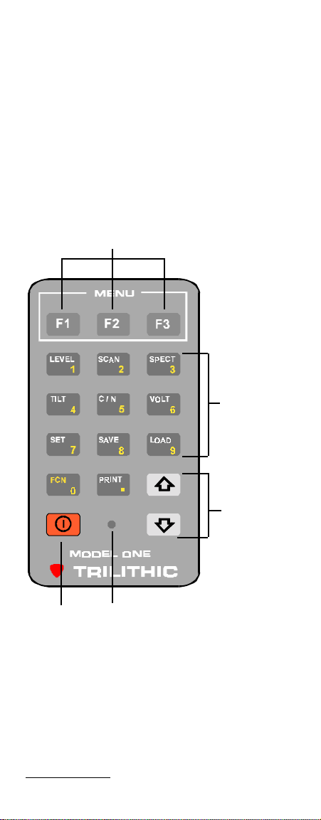
KEY PAD
The key pad consists of the various
buttons to access the Model One’s
functions. There are eleven function
buttons, two arrow buttons (up, down), the
power on/off button and three “soft
buttons” which enable you to perform
functions in the display.
“Soft” Buttons
11 Primary
and
Secondary
Function
Buttons
2 Arrow
Buttons
Power Charge Indicator
ON/OFF Light
Model One Operating Manual ""! TRILITHIC
10 –
Model One Walkthrough
Page 14
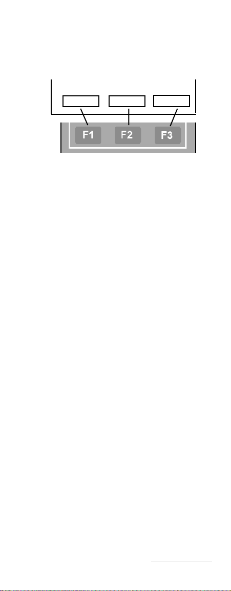
Soft Buttons
F1, F2 and F3 are used to access various
functions within the display menus. On
specific displays, three boxes appear at
the bottom of the display.
ENTER
!
!
These boxes correspond to the three soft
keys and provide additional commands
such as ENTER, EXIT, NOTE (for making
personal notations), movement arrows,
etc. (See the individual function displays
for more information).
Power ON/OFF
Use the POWER ON/OFF button to turn
the meter on and off.
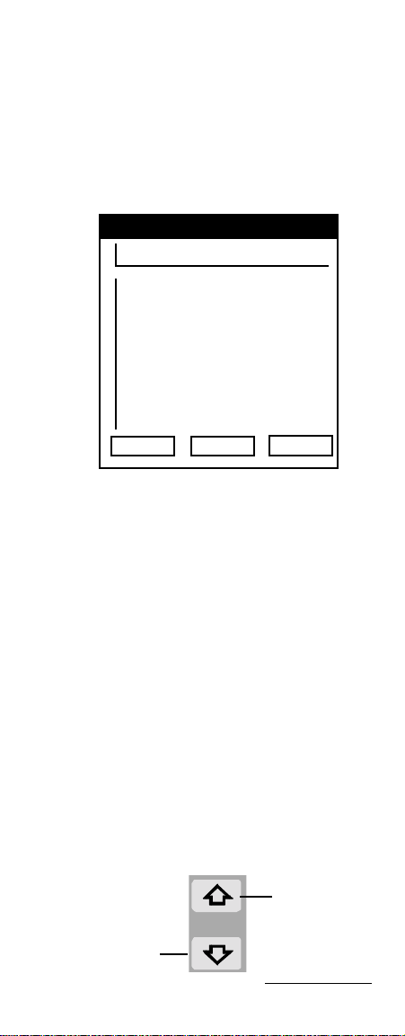
Arrow Buttons
The UP and DOWN ARROW buttons are
used to change values (i.e. Channel
Number, Frequency, etc.) within a function
display.
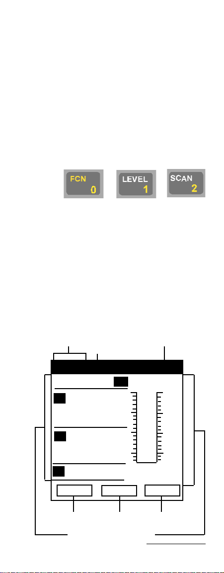
Function Buttons
The following is a list of the function
buttons:
Function No. Purpose
Level 1 Enter Single Channel/
Frequency
Measurement
Scan 2 Enter Channel Spec-
trum Scanning Mode
Spect 3 Enter Frequency Spec-
trum Scanning Mode
! TRILITHIC Model One Operating Manual
Model One Walkthrough
– 11
Page 15

Function No. Purpose
Tilt 4 Enter Tilt Measurement
Mode
C/N 5 Enter Carrier-to-Noise
Ratio Measurement
Mode
Volt 6 Check Voltage (battery
and power supply/drop)
Set 7 Set Up Display
Parameters
Save 8 Enables you to save the
Channel Scan display
data and record or scan
and save a new data
record
Load 9 Enables you to open
previously saved display
data or data record
FCN 0 Puts the key pad into a
second function
(i.e. enables you to input
numbers into a display)
Print . Print display data or
data record
Navigate Through Functions
You utilize several methods to navigate
through the Model One’s functions.
For some procedures, use the ARROW
buttons to make changes within a specific
screen such as to increase or decrease
values.
To scroll through a specific display’s menu
topics, use the designated “soft” buttons
(usually F2 and F3).
Model One Operating Manual ""! TRILITHIC
12 –
Model One Walkthrough
Page 16
NOTE: The Model One does not
support a “wrap around” feature. If
you are at the bottom of a menu list
and wish to go to the top, you will
need to press the UP arrow
indicator rather than continue
pressing the DOWN arrow.
Within several displays, you will want to
enter numeric values. Press the FCN
button to put the key pad in it’s secondary
function mode and then press the number
buttons to enter the desired value. For
example, to enter the number 12:
Press + +
Then press the “soft” button for ENTER
(i.e F1) to record the value into the Model
One.
If you make an error, you can press F2 to
cancel the number and then reenter it.
Press F3 to quit or exit the operation.
Display Screen Description
Each display contains the following
sections or features.
Time
FCN
Indicator
Display Indicator
19:16:30FCN LEVEL
6.8
–12.5
19.3
TV
15
5
–5
–15
– 13Model One Walkthrough
CH 17CH 17
CH 17
CH 17CH 17
V
103.25M dBmV
A
107.75M dBmV
""
"
""
FREQ SCALE REF
F1 F2 F3
Main Display Screen
! TRILITHIC Model One Operating Manual
Page 17

• Time – Displays unit’s time based
on time set up parameter (see page
xx)
• FCN – Indicates when the FCN
button has been pressed and the
key pad is in its secondary function
(see page 9)
• Display Indicator – Indicates which
meter function is being used
• Main Display Screen – Displays the
parameters and graphs of the
selected function
• F1, F2, F3 – Indicates the available
usage for the soft buttons in the
selected meter function
NOTE: The soft buttons vary from
meter function to meter function
(see Soft Buttons page 11).
Battery Charging
The Model One has a built-in 7.2V/1.8AH
Ni-MH battery. When fully charged, it can
be used for over three hours.
When the voltage of the battery drops
below 6.4V, the battery symbol flashes in
the information line at the top of the
display screen.
Flashing battery symbol
indicates low voltage
19:16:30 SETUP
GENERAL GENERAL
GENERAL
GENERAL GENERAL
# DATE & TIME
ENTER NEW DATE:
Y/M/D 2000/06/21
ENTER NEW TIME:
ENTER
Model One Operating Manual ""! TRILITHIC
14 – Model One Walkthrough
14:47:51
!
!
Page 18

NOTE: If the voltage drops below
6.2V, the Model One shuts off
automatically to protect the battery.
You will not be able to turn the meter
on again until you recharge the
battery.
To charge the Model One’s battery,
connect the charge cube to the charge
socket on the bottom of the meter (see
page 9) and plug the charger into an
outlet.
WARNING: The Model One’s battery
MUST be charged with the Trilithic
charger provided with the meter.
Using any other charger may damage
the battery.
Allow twelve to sixteen hours to charge the
battery fully.
! TRILITHIC Model One Operating Manual
– 15Model One Walkthrough
Page 19

Model One Operating Manual ""! TRILITHIC
16 –
Model One Walkthrough
Page 20

3
MODEL ONE
SETUP
Introduction
When you first press the POWER ON/OFF
button, the Model One displays it’s
INFORMATION screen briefly and then
displays the last screen it was on when it
was powered down.
CAUTION: Your unit’s battery may
need charging prior to use (see page
14).
Before using the Model One, you need to
perform some set up procedures which
include:
• Information (general information
about your meter)
• General (date and time, contrast for
the LCD display, volume, etc.)
• Measurement (signal level units,
temperature units, scan audio,
transmission, etc.)
• Channel Plan (set up the channel
plan to use for testing)
NOTE: Model One software may be
used to set up the meter. It also
enables you to restrict access to the
MEASUREMENTS and CHANNEL
PLAN menus.
To enter the set up display, press the SET
button.
! TRILITHIC Model One Operating Manual
Model One Setup
– 17
Page 21
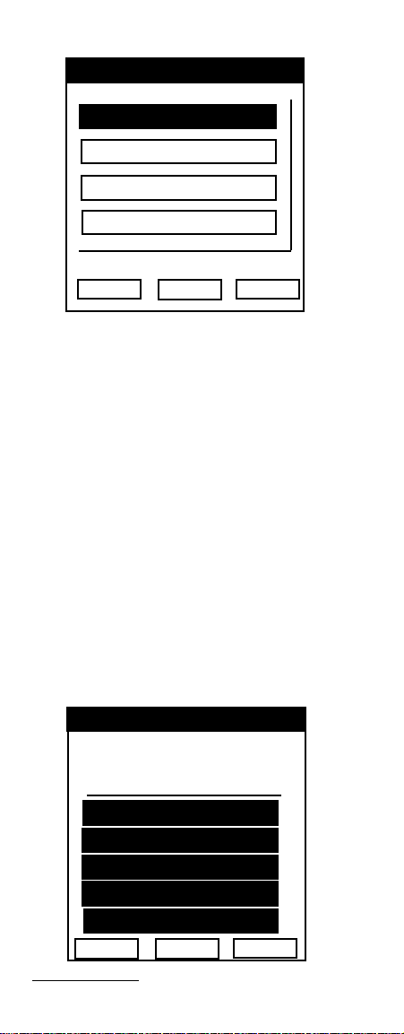
This brings up the SETUP menu.
19:16:30 SETUP
INFORMAINFORMA
INFORMA
INFORMAINFORMA
GENERALGENERAL
GENERAL
GENERALGENERAL
MEASURMENTMEASURMENT
MEASURMENT
MEASURMENTMEASURMENT
CHANNEL PLCHANNEL PL
CHANNEL PL
CHANNEL PLCHANNEL PL
ENTER
TIONTION
TION
TIONTION
!
ANAN
AN
ANAN
!
Use F2 and F3 arrows to scroll down the
menu list of command boxes.
REMINDER: The Model One does
not have a “wrap around” feature. If
you are at the bottom of the menu list
and wish to return to the middle or
top, you will need to press the UP
arrow to return to the top.
When the desired command is highlighted, press F1 (ENTER) to select the
display.
Information Display
The INFORMATION display window
contains useful information regarding your
Model One.
19:16:30
MODEL ONE
Field strength meter
NVER: x.xxxxxxxxx
SERIAL NO. xxxxxxxx
CAL DATE: xx/xx/xx
REMOTE ADDRESS 1
TEMPERATURE 73.0 F
EXIT
Model One Operating Manual ""! TRILITHIC
Model One Setup
18 –
Page 22
The information includes the unit’s
firmware version, serial number, calibration date, remote address and current
internal temperature.
General Display
Use the GENERAL Display screen to set
the performance parameters of your unit.
19:16:30 SETUP
GENERAL GENERAL
GENERAL
GENERAL GENERAL
BACKLIGHT YES
LCD CONTRAST
SHUTDOWN TIME
DATE & TIME
VOLUME
PRINTER SETUP
LCD TEST
PRIOR MENU
ENTER
Access the specific parameters the same
way you entered the display. Use F2 and
F3 to scroll through the command choices
and press F1 to enter the field for the
desired parameter.
!
!
BACKLIGHT
Press F1 (Enter) to toggle between ON
and OFF. If the LCD backlight is ON, the
meter will indicate YES beside that
parameter. If OFF, the meter will indicate
NO.
LCD CONTRAST
Use F2 or F3 to scroll to the LCD CONTRAST parameter. Use the UP arrow
button on the key pad to DARKEN the
contrast and the DOWN arrow to
BRIGHTEN.
darken
contrast
brighten
contrast
! TRILITHIC Model One Operating Manual
Model One Setup
– 19
Page 23

NOTE: Since the Model One memorizes the video parameter set up, be
careful not to set the display contrast
too low. This may cause the liquid
display to be too dim or not visible at
all which can affect your meter’s
operation.
SHUTDOWN TIME
The Model One’s automatic shutdown
timer can be adjusted to one of several
parameters. You may set it so that it will
stay on until you manually turn it off.
You can also set it so it will shut off after
there has been no key pad activity for a
specified time interval (3 minutes, 5
minutes, 10 minutes or 30 minutes). By
setting it to one of the timer shut offs, you
can save battery power during periods of
inactivity.
Use F2 or F3 to scroll to the SHUTDOWN
TIME parameter. Press F1 to enter the
SHUTDOWN screen.
19:16:30 SETUP
GENERAL GENERAL
GENERAL
GENERAL GENERAL
# SHUTDOWN TIMER
ALWAYS ON
3 MINUTES
5 MINUTES
10 MINUTES
30 MINUTES
ENTER
!
!
To select the desired shutdown parameter,
use F2 or F3 to scroll to the desired time.
Then press F1. The unit will return to the
GENERAL display.
Model One Operating Manual ""! TRILITHIC
20 –
Model One Setup
Page 24

To have the unit remain on until you turn it
off, select ALWAYS ON. To set the
automatic shutdown function, select either
3 MINUTES, 5 MINUTES, 10 MINUTES or
30 MINUTES. If you choose any of the
automatic shutdown times, the unit will
turn off in the designated time if there is no
key pad activity (pressing of buttons).
DATE & TIME
Use F2 or F3 to scroll to the DATE & TIME
parameter. Press F1 to enter the screen.
19:16:30 SETUP
GENERAL GENERAL
GENERAL
GENERAL GENERAL
# DATE & TIME
ENTER NEW DATE:
Y/M/D 2000/06/21
ENTER NEW TIME:
14:47:51
ENTER
!
!
Since you will be inputting data, you need
to switch the meter to the numeric
function. Press the FCN button.
You may change the order of the date
(month/date/year) to any order. Use the
UP and DOWN arrow keys to rearrange
the order. To enter the date, use the
numeric keys (1 - 0).
NOTE: There is no back key. If you
make an error, use F2 to scroll to the
TIME entry and then F3 to return to
the DATE line. This will restore the
date line to the previous entry.
! TRILITHIC Model One Operating Manual
Model One Setup
– 21
Page 25

NOTE: The Model One automatically
assigns the first two digits in the year
(20). When entering the year, you
only need to add the last two digits.
When the DATE is entered, press F2.
This scrolls you down to the TIME line.
Enter the desired time via the numeric
(FCN) buttons.
NOTE: The Model One is based on a
24 hour clock. For example, 3:15:49
PM should be input as 15:15:49.
Press F1 (ENTER) to log the change and
return to the GENERAL display.
VOLUME
Use F2 or F3 to scroll to the VOLUME
parameter. Press the UP arrow button to
INCREASE volume and the DOWN arrow
button to DECREASE volume.
increase
volume
decrease
volume
PRINTER SETUP
The Model One enables you to print both
the current display screen or a specific
report. See PRINTER OPERATION page
66 for more information.
Model One Operating Manual ""! TRILITHIC
22 – Model One Setup
Page 26

Scroll to the PRINTER SETUP command
and press F1.
19:16:30 SETUP
GENERAL GENERAL
GENERAL
GENERAL GENERAL
# PRINTER SETUP
PRINT SCREEN
PRINT REPORT
ENTER
!
!
You may print either the current display or
a report. Use F2 or F3 to select the
desired printing job.
LCD TEST
Scroll to LCD TEST and press F1. The
meter will execute several patterns to test
each of the LCD’s display points. The
patterns should appear as all white, all
black, vertical stripe and then checkerboard.
NOTE: If the temperature is below
0°C, the display speed of the LCD will
slow down.
Once the parameters have been set to
your specifications, scroll to PRIOR MENU
and press F1. This returns you to the SET
UP display.
Measurement Display
Once your meter’s parameters have been
established and you are back to the main
set up menu, use F2 or F3 to scroll to the
MEASUREMENT command box.
! TRILITHIC Model One Operating Manual
– 23Model One Setup
Page 27

Press F1 to enter the MEASUREMENT
display so that you can set up the meter’s
measurement parameters.
19:16:30 SETUP
MEASUREMENTS MEASUREMENTS
MEASUREMENTS
MEASUREMENTS MEASUREMENTS
SCAN AUDIO NO
SCAN ENABLED NO
TRANSMISSION NO
LIMIT SETUP
FREQ TUNING STEP
SIGNAL LEVEL UNITS
TEMPERATURE UNITS
PRIOR MENU
# LOAD DEFAULT #
ENTER
!
!
SCAN AUDIO
Use F2 or F3 to scroll to SCAN AUDIO.
Use F1 to toggle this parameter between
ON and OFF (YES or NO).
Select YES if you want the meter to graph
Audio and Video carriers with the CHANNEL SCAN function.
If you select NO, only the Video carriers
will be graphed. However, both Audio and
Video levels will be shown on the display
and printed reports.
NOTE: When SCAN AUDIO is
selected (YES), only a maximum of
50 channels are viewable on the
display at one time. Use the UP and
DOWN arrow buttons on the key pad
to change the displayed frequency
spectrum in order to see additional
channels.
SCAN ENABLED
When the SCAN ENABLED function is
selected, the Model One scans only the
active channels in the Channel Plan. This
provides the most efficient access to your
CATV system information.
Model One Operating Manual ""! TRILITHIC
24 –
Model One Setup
Page 28

Use F2 or F3 to scroll to SCAN ENABLED.
Use F1 to toggle this parameter between
ON and OFF (YES or NO).
TRANSMISSION
Scroll to TRANSMISSION and press F1 to
toggle the parameter between enabled
and disabled (YES or NO). Use this
parameter to test for transmission characteristics and loss of in-between connections in your CATV system.
LIMIT SETUP
Scroll to this parameter to set the limits of
the meter so that you can conduct limit
tests. Press F1 to enter the LIMITS
display. Here, you can select the LIMIT
DISPLAY and edit the limits.
19:16:30 SETUP
MEASUREMENTS MEASUREMENTS
MEASUREMENTS
MEASUREMENTS MEASUREMENTS
# LIMIT SETUP
LIMIT DISPLAY NO
EDIT LIMIT
PRIOR MENU
ENTER
!
!
You can display the limit lines and a
PASS/FAIL indication for each channel
and the viewable scan spectrum, during
channel spectrum scanning. Limits are
not used to determine Pass or Fail for
SGNL and DIGI type channels (see
Channel Spectrum Scanning Measurement page 44). To enable or disable this
function, scroll to LIMIT DISPLAY and then
press F1 to toggle the function from off to
on (NO to YES).
! TRILITHIC Model One Operating Manual
Model One Setup
– 25
Page 29

NOTE: To print the Pass or Fail
status of each channel on a report,
set LIMIT DISPLAY to YES.
19:16:30 SETUP
MEASUREMENTS MEASUREMENTS
MEASUREMENTS
MEASUREMENTS MEASUREMENTS
# LIMIT SETUP
LIMIT DISPLAY YES
EDIT LIMIT
PRIOR MENU
ENTER
!
!
To edit the limits, scroll to EDIT LIMITS
and press F1.
19:16:30 SETUP
MEASUREMENTS MEASUREMENTS
MEASUREMENTS
MEASUREMENTS MEASUREMENTS
$$$$# EDIT LIMIT
SET FOR DEFAULT
MIN VIDEO 60dBµV
MAX ∆VID LEVEL 13dB
MAX ∆V/A 17dB
MIN ∆V/A 10dB
SAVE AND EXIT
ENTER
!
!
In this screen, you will need to select the
minimum video level (40dBµV to
120dBµV), maximum ∆ video level (2dB
to 30dB), maximum ∆ video/audio
difference (5dB to 30dB), and minimum ∆
video/audio difference (0dB to 15dB). To
enter the levels, use F2 or F3 to scroll to
each limit.
Press FCN to toggle the key pad to
numeric entry mode.
Model One Operating Manual ""! TRILITHIC
26 –
Model One Setup
Page 30

Enter the desired level for the parameter.
Press F1 to save the parameter and move
to the next limit.
NOTE: If you press F2 or F3 to scroll
BEFORE you press F1, you will
remain on the limit you just edited
and the UP/DOWN key will delete the
entry instead of moving to the next
limit.
Once you have set the levels for each
parameter, scroll to SAVE AND EXIT and
press F1. The Model One returns to the
LIMIT SETUP screen.
Once the limits are set, scroll to PRIOR
MENU and press F1 to return to the
MEASUREMENTS setup screen.
FREQ TUNING STEP
Use the FREQUENCY TUNING STEP to
select the meter’s internal step values.
These steps can be either 10 kHz, 100
kHz, 1 MHz or 10 MHz.
Use F2 or F3 to scroll to FREQ TUNING
STEP and press F1 (ENTER).
19:16:30 SETUP
MEASUREMENTS MEASUREMENTS
MEASUREMENTS
MEASUREMENTS MEASUREMENTS
$# FREQ TUNING STEP
10 KHz
100 KHz
1 MHz
10 MHz
CHANNEL STEP
ENTER
!
!
Use F2 or F3 to scroll to the desired
tuning step. Press F1 (ENTER) when the
value you want is highlighted. The Model
One will return to the MEASUREMENTS
set up screen.
! TRILITHIC Model One Operating Manual
Model One Setup
– 27
Page 31

SIGNAL LEVEL UNITS
Use F2 or F3 to scroll to SIGNAL LEVEL
UNITS. Press F1 to enter the parameter
display.
19:16:30 SETUP
MEASUREMENTS MEASUREMENTS
MEASUREMENTS
MEASUREMENTS MEASUREMENTS
# SIGNAL LEVEL UNITS
dBµV
dBmV
dBmW
ENTER
!
!
You may set the signal level units to test for
dBµV, dBmV or dBmW. Scroll between the
values with F2 or F3 and press F1 when the
desired value is highlighted. The meter will
return to the MEASUREMENT display.
TEMPERATURE UNITS
Scroll to TEMPERATURE UNITS and press
F1.
19:16:30 SETUP
MEASUREMENTS MEASUREMENTS
MEASUREMENTS
MEASUREMENTS MEASUREMENTS
# TEMPERATURE UNITS
CENTIGRADE
FARENHEIT
ENTER
You may set the meter to read either Centigrade or Fahrenheit. Scroll between the two
with the F2 and F3 buttons. Once the desired
setting is highlighted, press F1 to select the
setting and return to the MEASUREMENT
setup screen.
!
!
Model One Operating Manual ""! TRILITHIC
28 –
Model One Setup
Page 32

LOAD DEFAULT
Since the Model One has the capability to
memorize and store its various parameters and settings, you may restore it to its
initial default settings at anytime.
If you wish to restore the Model One to the
default settings, scroll to LOAD DEFAULT
and press F1. The meter will return to all
of its default settings.
NOTE: If you select the LOAD
DEFAULT command, the meter does
not return to the MEASUREMENTS
setup screen when you press F1.
Instead, it displays the INFORMATION screen briefly and then goes to
the LEVEL display screen. To return
to the MEASUREMENTS screen,
press SET to return to the SETUP
screen, scroll to MEASUREMENTS
and press F1 (ENTER).
PRIOR MENU
Once you have set up the Model One’s
parameters to the desired settings and
values, use F2 or F3 to scroll to PRIOR
MENU. Press F1 (ENTER) to return to the
SETUP display screen.
Channel Plan Display
One of the most useful functions of the
Model One, is its ability to generate a
user-selected Channel Plan based on your
own specific system as well as provide
you with existing default channel plans.
! TRILITHIC Model One Operating Manual
Model One Setup
– 29
Page 33

To enter the CHANNEL PLAN DISPLAY,
go to the SETUP screen, scroll to CHANNEL PLAN and press F1.
19:16:30 SETUP
CHANNEL PL CHANNEL PL
CHANNEL PL
CHANNEL PL CHANNEL PL
ANAN
AN
ANAN
LEARN CHANNEL PLAN
EDIT CHANNEL PLAN
TILT/FAVORITE
PRIOR MENU
ENTER
!
!
LEARN CHANNEL PLAN
You can use either an existing channel
plan that comes with the meter or use one
of these to customize your own. To learn
a channel plan, scroll to LEARN CHANNEL PLAN and press F1.
CAUTION: Before starting the
learning session, make sure your
Model One is hooked up to your
CATV system.
19:16:30 SETUP
CHANNEL PL CHANNEL PL
CHANNEL PL
CHANNEL PL CHANNEL PL
$#LEARN CHANNEL PLAN
HRC CATV
NCTA CATV
PAL I CATV
PAL B/G CATV
JPN CATV
ENTER
!
ANAN
AN
ANAN
!
Once the list of channel plans is displayed, use F2 or F3 to scroll through the
list. When the desired channel plan is
highlighted, press F1.
Model One Operating Manual ""! TRILITHIC
Model One Setup
30 –
Page 34

The meter searches for active channels in
your system. A “progress bar” indicates
search progress.
19:16:30 SETUP
CHANNEL PL CHANNEL PL
CHANNEL PL
CHANNEL PL CHANNEL PL
ANAN
AN
ANAN
$#LEARN CHANNEL PLAN
HRC CATV
NCTA CATV
PAL I CATV
PAL B/G CATV
JPN CATV
Ch 17
ENTER
!
!
progress bar current channel
added to plan
Once the search is completed, the Model
One displays the prompt that the new
channel plan is being saved. This channel
plan contains all active channels. Those
channels that did not transmit a signal will
not be included.
EDIT CHANNEL PLAN
Once your channel plan has been learned,
you may then modify the various parameters in the plan. Scroll to EDIT CHANNEL PLAN and press F1.
19:16:30 SETUP
CHANNEL PL CHANNEL PL
CHANNEL PL
CHANNEL PL CHANNEL PL
$#EDIT CHANNEL PLAN
CHN TYPE FREQ ENA
14 TV 121.25 %
15 TV 127.25 %
16 TV 133.25 %
17 TV 139.25 %
18 TV 145.25 %
ENTER
!
ANAN
AN
ANAN
!
! TRILITHIC Model One Operating Manual
Model One Setup
– 31
Page 35

Within the EDIT CHANNEL PLAN display,
use F2 or F3 to scroll through the list of
channels. All channels that have been
enabled by the LEARN CHANNEL PLAN
will have a checkmark under ENA.
$# EDIT CHANNEL PLAN
CHN TYPE FREQ ENA
14 TV 121.25 %
When the desired channel you wish to
modify is highlighted, press F1 (ENTER).
19:16:30 SETUP
CHANNEL PL CHANNEL PL
CHANNEL PL
CHANNEL PL CHANNEL PL
ANAN
AN
ANAN
$#EDIT CHANNEL PLAN
CHANNEL NUMBER 16
ENABLED YES
TYPE TV
SCRAMBLED NO
FREQUENCY: 133.25MHz
AUD OFFSET 4.50MHz
SAVE AND EXIT
ENTER
!
!
To change the channel’s parameters, use
F2 and F3 to scroll up and down the list.
There are different methods for modifying
each parameter.
NOTE: When using the FCN button,
remember to press F1 once you have
made the desired edit. Otherwise, if
you use F2 or F3 to scroll, you will
change your modification rather than
move to the next parameter.
Channel Number – When the channel
number is highlighted, press FCN to
enable the numeric key pad. Enter the
desired number for the channel (0 - 199).
Once the channel number is modified,
press F1 to save the edit. The Model One
scrolls to the ENABLED edit line.
Model One Operating Manual ""! TRILITHIC
32 –
Model One Setup
Page 36

Enabled – When the ENABLED line is
highlighted, press F1 to toggle between on
or off (YES or NO).
Type – Use F1 to toggle between the
channel types (TV, SIGL, or DIGI).
NOTE: The rest of the parameters in
the edit list are affected by which type
of channel you select.
TV – Audio and Video Carriers (parameters: Scrambled, Frequency, AUD
Offset
SIGL – Single Frequency Channels
(parameters: Scrambled, Frequency)
DIGI – Digital Channels (parameters:
Scrambled, Frequency, Measure BW)
Scrambled – Use F1 to toggle between
YES and NO.
Frequency – To change the video
frequency of the channel, press the FCN
button to enable the numeric key pad.
NOTE: The new frequency you enter
should always be less than 870 MHz.
Once the desired modification is made,
press F1 to save the edit and exit the FCN
mode.
AUD Offset (TV type only) – Use this
parameter to change the positive offset of
the audio frequency from the video carrier.
When this parameter is highlighted, press
the FCN button to enable the numeric key
pad.
NOTE: The sum of this offset and the
video carrier frequency should never
be more that 870 MHz.
Once the desired modification is made,
press F1 to save the edit and exit the FCN
mode.
! TRILITHIC Model One Operating Manual
Model One Setup
– 33
Page 37

Measure BW (Digi type only) – When this
parameter is highlighted, press the FCN
button to enable the numeric key pad.
Once the desired modification is made,
press F1 to save the edit and exit the FCN
mode.
When you have made the desired edits to
the channel parameters, scroll to SAVE
AND EXIT and press F1. The Model One
returns to the EDIT CHANNEL PLAN
screen.
NOTE: Once you have modified the
channels in the existing plan, you will
need to press a function button (i.e.
SET) to exit the EDIT CHANNEL
PLAN screen.
CAUTION: Whenever you learn a
new Channel Plan, the previously
edited parameters will be overwritten
by the new plan and all files that were
saved with the previous plan will be
deleted.
TILT/FAVORITE
The Model One enables you to select up
to eight “favorite” channels. These
channels are also used when making the
Tilt measurement.
NOTE: You must select at least
FOUR channels to make the Tilt
Measurement. The Model One uses
the highest and lowest frequencies
when making the measurement.
Model One Operating Manual ""! TRILITHIC
34 – Model One Setup
Page 38

To enter the TILT/FAVORITE screen, scroll
to TILT/FAVORITE and press F1.
19:16:30 SETUP
CHANNEL PL CHANNEL PL
CHANNEL PL
CHANNEL PL CHANNEL PL
ANAN
AN
ANAN
$#TILT/FAVORITE
CHN FREQ TILT
14 121.25
15 127.25
16 133.25
17 139.25
18 145.25
ENTER
!
1
2
3
4
5
6
7
8
!
To add a channel to the FAVORITES list,
use F2 and F3 to scroll the list of channels. When the desired channel is
highlighted, press F1.
A check mark appears next to the channel
under the TILT column and the channel
number is placed in the FAVORITES
column on the right of the display.
19:16:30 SETUP
CHANNEL PL CHANNEL PL
CHANNEL PL
CHANNEL PL CHANNEL PL
$#TILT/FAVORITE
CHN FREQ TILT
14 121.25 %
15 127.25
16 133.25 %
17 139.25
18 145.25
ENTER
!
ANAN
AN
ANAN
1 4
2 6
3 14
4 16
5
6
7
8
!
favorites list
As you add channels, the FAVORITES list
arranges them in order of their frequency.
For example, even if you selected Channel 14 first, as you add Channels 4 and 6,
these channels go to the top of the list.
! TRILITHIC Model One Operating Manual
– 35Model One Setup
Page 39

Once you have selected up to eight
favorite channels, press a function button
(i.e SET) to exit the TILT/FAVORITE
screen.
If you want to replace a TILT/FAVORITE
channel, use F2 or F3 to scroll to the
channel to be deleted. Press F1. Go to
the replacement channels and press F1.
REMINDER: For the TILT
MEASUREMENT feature to function,
you must have at least FOUR
channels in the FAVORITES list.
Model One Operating Manual ""! TRILITHIC
36 – Model One Setup
Page 40

BASIC
OPERATION
Introduction
Once you have set up the Model One’s
parameters, you are ready to operate the
unit. The Model One supports a number
of functions that are accessed via buttons
on the key pad. There are eleven
function buttons on the Model One’s key
pad.
4
These include:
• Level – Enter Single Channel/
Frequency Measurement (see page
38)
• Scan – Enter Channel Spectrum
Scanning Mode (see page 44)
• Spect – Enter Frequency Spectrum
Scanning Mode (see page 48)
• Tilt – Enter Tilt Measurement Mode
(see page 34 and page 51)
• C/N – Enter Carrier-to-Noise Ratio
Measurement Mode (see page 51)
• Volt – Check Voltage (battery and
power supply/drop) (see page 53)
! TRILITHIC Model One Operating Manual
Basic Operation
– 37
Page 41

• Set – Set Up Display Parameters
(see page 17)
• Save – Enables you to save the
display data or data record (see
page 60)
• Load – Enables you to open
previously saved display data or
data record (see page 64)
• FCN – Puts the key pad into a
second function (i.e. enables you to
input numbers into a display) (see
page 13)
• Print – Print display data or data
record (see page 66)
NOTE: When you power ON your
meter, it will display briefly the
INFORMATION screen and then
display the last screen it was in prior
to power off.
Single Channel Level Test
When set to the single channel level test,
the Model One displays bar graphs of the
video and audio carriers as well as
numeric readouts of the carrier amplitudes
and V/A difference. The meter can also
display a spectrum scan showing the
amplitudes of the video and audio carriers
and undesired signals that may be present
such as intermodulation.
To access the LEVEL screen, press the
LEVEL button.
The Model One displays the LEVEL
screen for the last channel it was on
before being turned off.
Model One Operating Manual ""! TRILITHIC
38 –
Basic Operation
Page 42

TV CHANNELS
3
3
3
3
3
3
3
3
3
3
3
3
3
3
3
3
3
3
3
3
3
3
3
When measuring a TV type channel with
audio and video carriers (see Edit Channel
Plan page 31), the left column of the bar
graph represents the video carrier while
the right column displays the audio carrier.
The V/A ∆ is displayed below the video
and audio carriers.
Channel Type
19:16:30 LEVEL
61.8
47.1
13.7
TV
2
2
2
2
2
2
2
2
2
2
2
2
2
2
2
2
2
2
2
2
2
2
2
Video Carrier
Audio Carrier
76
66
56
46
36
CH 17CH 17
CH 17
CH 17CH 17
V
139.25M dBµV
A
143.75M dBµV
""
"
""
FREQ SCALE REF
F1 F2 F3
∆∆
V/A
∆
∆∆
Audio Carrier
Video Carrier
To change the channel, use the UP and
DOWN arrow buttons on the keypad or
press the FCN button and enter the
desired channel number.
The LEVEL screen displays a scale which
you can adjust by pressing F2 (SCALE).
This enables you to vary the graduation of
the scale according to a 1, 2, 5, 10dB
scale.
! TRILITHIC Model One Operating Manual
Basic Operation
– 39
Page 43

For example, to change the display graph
3
3
3
3
3
3
3
3
3
3
3
3
3
3
3
3
3
3
3
3
3
3
3
3
3
3
3
3
3
12
12
12
12
12
12
12
12
12
12
12
12
12
12
12
12
12
12
3
3
3
3
3
3
3
3
3
3
3
3
3
from a 10dB scale to a 5dB scale, press
F2 twice to cycle through the steps.
Press SCALE
76
2
2
2
66
2
2
2
2
2
56
2
2
2
2
2
2
2
2
46
2
2
2
2
2
2
2
2
36
to
to go from:
2
2
2
2
2
↓↓
↓
↓↓
76
71
66
61
56
10dB 5dB
NOTE: The display graph of the
scale adjusts as you change the scale
parameters. When the value falls
below the scale, the bar graph is
replaced with an arrow.
You may also change the reference level
of the graph. Press F3 (REF) and then
press F1 (REF–) or F2 (REF+) to increase
or decrease the scale references a single
digit at a time.
Press REF
Press REF – or REF +
76
66
56
2
2
2
2
46
2
2
2
2
36
2
2
2
2
2
↓↓
↓
↓↓
The Model One can scan the spectrum of
the designated channel automatically.
This function is particularly useful for
CATV measurements.
Model One Operating Manual ""! TRILITHIC
40 –
Basic Operation
71
61
51
41
31
Page 44

To scan the channel spectrum, press
7
7
7
7
7
7
7
7
7
7
7
7
7
LEVEL again. The Model One displays
the spectrum screen and scans the
channel for data which it then graphs on
the screen.
19:16:30 LEVEL
....................................
...................................
........................................
........................................
..........................................
........................................
..................................................
20
o
-20
-40
CF 79.50M CH 5
MKR 79.50M ---.-dBmV
REF – REF + SCALE
The Center Frequency and Channel
Number are displayed along with the
Marker Frequency and level.
Use the UP and DOWN arrow buttons to
move the Marker Frequency to any
position in the channel spectrum.
SINGLE FREQUENCY CHANNELS
You can use the Model One to measure
only the Center Frequency. To do this,
first set the meter’s channel type to SGNL
or single frequency channel (see Edit
Channel Plan page 31).
13:24:53 LEVEL
CH 14 SIGL
23456
23456
23456
23456
23456
23456
23456
23456
23456
23456
23456
23456
23456
20
10
0
–10
-20
– 41
F
–00.9
121.25M dBmV
! TRILITHIC Model One Operating Manual
FREQ SCALE REF
Basic Operation
Page 45

To scan the channel spectrum, press
7
7
7
7
7
7
7
7
7
7
7
7
7
LEVEL again.
13:25:34 LEVEL
....................................
...................................
........................................
........................................
..........................................
........................................
..................................................
20
o
-20
-40
CF 121.25M CH 14
MKR 121.25M -01.3dBmV
REF – REF + SCALE
DIGITAL CHANNELS
You can use the Model One to measure
the average power of a digital channel
according to the configured bandwidth. To
do this, first set the meter’s channel type
to DIGI (see Edit Channel Plan page 31).
13:24:03 LEVEL
CH 207 DIGI
P
9.4
45.25M dBmV
BW 5.50M
23456
23456
23456
23456
23456
23456
23456
23456
23456
23456
23456
23456
23456
20
10
0
–10
-20
FREQ SCALE REF
Model One Operating Manual ""! TRILITHIC
42 –
Basic Operation
Page 46

To scan the channel spectrum, press
LEVEL again.
13:41:54 LEVEL
....................................
...................................
........................................
........................................
..........................................
........................................
..................................................
CF 45.25M CH 207
MKR 45.25M -03.0dBmV
REF – REF + SCALE
20
o
-20
-40
Frequency Mode
When set to the FREQUENCY Mode, the
Model One displays the frequency and
level for the desired channel.
To access this screen, press the LEVEL
button.
The SINGLE CHANNEL LEVEL screen is
displayed.
Now, press F1 (FREQ).
FREQ SCALE REF
F1 F2 F3
This toggles the meter so that it displays
the FREQUENCY screen for the channel
designated in the SINGLE CHANNEL
LEVEL screen.
If the channel is a “TV” type channel with
audio and video carriers, the meter will be
tuned to the audio frequency. Also, if the
volume has been set in the GENERAL
SETUP menu, Audio will be heard in this
FREQUENCY Mode.
! TRILITHIC Model One Operating Manual
– 43Basic Operation
Page 47

19:16:30 LEVEL
6
6
6
6
6
6
6
6
2345
2345
2345
2345
2345
2345
2345
2345
5
–05
–15
–25
–35
FREQUENCY
143.75M
LEVEL
–13.7
dBmV
ATTEN: 00dB
CHAN SCALE REF
To change the frequency that is being
measured, press the UP and DOWN arrow
buttons on the keypad. The frequency will
move in increments set in the MEASUREMENTS SETUP menu.
NOTE: By pressing the FCN button,
you can enter the desired frequency.
To finish, press F1 (ENTER).
Press F2 (SCALE) to adjust the display
scale in 1,2,5,10dB increments (see page
40).
To adjust the reference level, press F3
(REF) and then F1 (REF–) or F2 (REF+)
(see page 40).
Channel Spectrum Scanning
Measurement
The Model One is designed to display the
full span of the video carriers in your
system. This function provides a quick
check of your system’s overall flatness
and amplitude.
The meter can also be set to display the
video and audio carriers at reduced
frequency spans. Amplitude limits can be
imposed on the display while a convenient
Frequency Marker enables you to zoom in
on any suspect channels.
Model One Operating Manual ""! TRILITHIC
44 –
Basic Operation
Page 48

To enter the CHANNEL SPECTRUM
SCANNING screen, press SCAN.
The currently selected channel plan
measurement data is displayed in a graph
with a viewing range of 100 data points
(this can be extended to 140 by adjusting
the Scan Marker line).
NOTE: If Scan Audio is selected, 50
channels (audio and video) are
viewable at a time.
19:16:30 SCAN
....................................
...................................
........................................
........................................
..........................................
........................................
..................................................
055M CH12 361M
$$
""
V 2.2 A -16.1
AUTO HOLD
$$$$$$$$$$$$$$$$$$$$
$
"
$$$$$$$$$$18.3dB
$$
""
$$$$$$$$$$$$$$$$$$$$
20
0
-20
-40
!
!
starting freq. ending freq.
scan marker
In addition to displaying the Marker
Channel and its video, audio and V/A ∆
levels, the Model One also displays the
LOW (starting) and HIGH (ending)
frequencies.
CHANNEL SPECTRUM SCANNING
supports four methods based on the
parameters selected in the MEASUREMENT setup screen (see page 23):
• SCAN ENABLE = YES - the meter
scans only the active (selected)
channels in the user- selected
Channel Plan (see page 29)
! TRILITHIC Model One Operating Manual
Basic Operation
– 45
Page 49

• SCAN ENABLE = NO - the meter
3
3
3
3
3
3
3
3
3
3
3
3
3
3
3
3
3
3
3
3
3
3
3
3
3
3
3
3
3
3
3
scans all channels
• SCAN AUDIO = NO - the meter
graphs only the video carriers of the
channels (numeric readout of video
and audio levels are displayed for
the marker channel)
• SCAN AUDIO = YES - the meter
graphs both the video and audio
carriers of the channels (numeric
readout of video and audio levels
are displayed for the marker
channel)
To change the channel being scanned,
press the UP or DOWN arrow buttons.
NOTE: You can increase the marker
movement resolution by pressing
FCN before pressing the UP/DOWN
arrow buttons to quickly move the
marker across the full channel plan
spectrum. Pressing FCN again
before using the UP/DOWN arrow
buttons causes the marker to return
to a movement of one channel at a
time.
You can zoom in on the graph by pressing
the SCAN button. The Model One
supports 5 levels of magnification. To
return to the original zoom level, just keep
pressing SCAN to cycle back.
20:04:45 SCAN
....................................
...................................
........................................
........................................
..........................................
........................................
..................................................
181M CH12 235M
V 1.7 A -16.1
Model One Operating Manual ""! TRILITHIC
46 –
AUTO HOLD
Basic Operation
2
2
2
2
2
2
2
2
2
2
2
2
2
2
2
2
2
2
2
2
2
2
2
2
2
2
2
2
2
2
2
$$
""
$
"
$$
""
$$$$$$$$$$$$$$$$$$$$
$$$$$$$$$$17.8dB
$$$$$$$$$$$$$$$$$$$$
20
0
-20
-40
!
!
Page 50

To set the reference level and the scale
automatically, press F1 (AUTO). The
Model One will select the optimal scope
for your system.
If you prefer to set the reference level and
scale yourself, press F3 (↓, ↑) (see page
40 for more information).
To adjust the reference level, press F1
(REF) and then press F1 (REF–) or F2
(REF+).
To change the scale, press F3 (↓, ↑) from
the main CHANNEL SPECTRUM SCANNING screen and then press F2 (SCALE)
until you have selected the desired scale
(2, 4, 10, or 20dB).
At any time, you can restore the Model
One to the optimal levels by pressing F1
(AUTO).
You may wish to stop the scanning
process so that you can study the graph
without losing the current data. In the
main CHANNEL SPECTRUM SCANNING
screen, simply press F2 (HOLD). The
scanning marker will stop moving. To
resume scanning, press F2 (TRIG).
LIMIT DISPLAY
If LIMIT DISPLAY is set to YES in the
MEASUREMENTS menu (see LIMIT
SETUP page 25), the Channel Spectrum
Scanning display will show the limit lines
for the minimum video level and maximum
∆ video level.
! TRILITHIC Model One Operating Manual
Basic Operation
– 47
Page 51

1
1
1
1
1
1
20:49:14 SCAN
1
1
1
1
1
1
1
1
1
1
1
1
1
2345678901234567890123456789012
2345678901234567890123456789012
2345678901234567890123456789012
....................................
2345678901234567890123456789012
2345678901234567890123456789012
2345678901234567890123456789012
...................................
........................................
2345678901234567890123456789012
2345678901234567890123456789012
2345678901234567890123456789012
........................................
2345678901234567890123456789012
2345678901234567890123456789012
2345678901234567890123456789012
..........................................
2345678901234567890123456789012
2345678901234567890123456789012
2345678901234567890123456789012
........................................
2345678901234567890123456789012
2345678901234567890123456789012
2345678901234567890123456789012
..................................................
2345678901234567890123456789012
30
10
-10
-30
193M CH59 487M F
$$
""
V -02.2 A -16.1
REF – REF +
$$$$$$$$$$$$$$$$
$
"
$$$$$$$$13.9 F
$$
""
$$$$$$$$$$$$$$$$
!
!
channel PASS or FAIL indicator
scan PASS or FAIL indicator
A “P” for PASS or “F” for FAIL appears for
each channel selected by the marker.
This indicates that the channel meets the
requirements which were set up in the
LIMITS EDIT menu: minimum video level,
maximum ∆ video level, maximum ∆
video/audio difference, and minimum ∆
video/audio difference (see page 26).
A PASS (P) or FAIL (F) indication is also
given for the displayed scan spectrum.
This will indicate “–” until the first scan is
completed. The channel status of a “DIGI”
or “SNGL” type channel is not used to
determine PASS or FAIL for the scan.
This is used ONLY for “TV” type channels
with audio and video carriers.
NOTE: A “pass/fail” status is not
available for single or digital channels.
Frequency Spectrum
Scanning Measurement
The Model One can be set to display
spectrum measurements with spans
ranging from 2 to 50 MHz. It can also be
set for a full spectrum scan (5 to 870 MHz)
with sampling at each video carrier
frequency in the selected channel plan.
Model One Operating Manual ""! TRILITHIC
48 – Basic Operation
Page 52

NOTE: The Model One can show
spectrum data with absolute
measurements or it can store data for
comparative tests using the TRANSMISSION feature.
TRANSMISSION mode is set up in
the MEASUREMENTS menu. Since
the following data is for normal
(absolute) spectrum scanning,
TRANSMISSION should be set to NO
in the MEASUREMENTS menu (see
page 25). For further information on
TRANSMISSION OPERATION, see
TRANSMISSION CHARACTERISTIC
TEST page 55.
The following information is for normal
(absolute) spectrum scanning.
To enter the FREQUENCY SPECTRUM
SCANNING screen, press SPECT.
The FREQUENCY SPECTRUM SCANNING screen is displayed.
20:36:14 SPECT
....................................
...................................
........................................
........................................
..........................................
........................................
..................................................
ST 07.00M SP --M
MKR 235.25M 6.8dBmV
HOLD SPAN
When the full spectrum scan is displayed,
the SPAN indicator will be “--M” (full span).
The starting frequency will be shown along
with the marker frequency and level.
! TRILITHIC Model One Operating Manual
Basic Operation
20
0
-20
-40
!
!
– 49
Page 53

To move the marker frequency, press the
UP or DOWN arrow buttons on the key
pad.
To change the scanning bandwidth, press
F2 (SPAN). The span cycles through 2M,
5M, 10M, 20M, 50M and --M (full span).
11:44:10 SPECT
....................................
...................................
........................................
........................................
..........................................
........................................
..................................................
CF 135.50M SP 10M
MKR 133.30M -02.4dBmV
HOLD SPAN
When a span other than full span (--M) is
selected, the display shows the center
frequency.
To change the center frequency, press
FCN to place the keypad in it’s second
function. Enter the desired new center
frequency and press F1 (ENTER).
20
0
-20
-40
!
!
If you enter an incorrect digit, do not press
F1. Instead, press F2 (BACK). You can
exit the procedure by pressing F3 (ESC) to
return to the original center frequency.
To change the reference levels, press F3
(↓, ↑), press F1 (REF) and then press F1
(REF–) or F2 (REF+).
To change the scale, press F3 (↓, ↑) from
the main FREQUENCY SPECTRUM
SCANNING screen and then F2 (SCALE).
If you want to stop the scanning process,
simply press F2 (HOLD). The channel
marker will stop moving. To resume
scanning, press F2 (TRIG).
Model One Operating Manual ""! TRILITHIC
50 –
Basic Operation
Page 54

Carrier-To-Noise
Measurement
To enter the C/N screen, press C/N.
The meter displays the C/N RATIO screen.
19:16:30 C/N
CH 17
VIDEO
1.2
dBmV
139.25M
C/N
AUTO SELECT
OFFSET FREQUENCY
The meter measures the C/N difference of
the selected channel. First, it measures
the video carrier level of the selected
channel.
THE CARRIER
LEVEL MUST
BE GREATER
THAN 25dBmV
NOTE: The video carrier level MUST
be greater than 25dBmV (85dBµV).
If the measured video carrier is greater
than 25dBmV (85dBµV), the meter will
display a “please wait...” message prompt.
Then, the meter measures the noise level
in the guard band of that channel and
calculates the measurement of the
affected channel. The value of the C/N
difference is displayed on the screen.
Tilt and Favorite Channel
When installing and maintaining your
CATV system, you may want to concentrate on only a few channels’ levels and
the gain distribution of the transmission
line.
! TRILITHIC Model One Operating Manual
Basic Operation
– 51
Page 55

You can use the TILT and FAVORITE
CHANNEL function to display and adjust
the level and work status of your system.
To enter the TILT AND FAVORITE
CHANNEL screen, press TILT.
REMINDER: Before you use the TILT
AND FAVORITE CHANNEL feature,
you must enter at least FOUR
channels in the TILT/FAVORITE
section of the CHANNEL PLAN set up
screen (see TILT/FAVORITE page
34).
19:16:30 TILT
....................................
...................................
........................................
........................................
..........................................
14 17
LOW -01.2 dBmV
HIGH -01.6 dBmV
TILT = -00.4 dB
REF– REF+ SCALE
35
15
-05
-25
The measured levels of the LOWEST and
HIGHEST frequencies listed in the TILT/
FAVORITE list are used to calculate tilt.
To adjust the reference level, press F1
(REF–) or F2 (REF+). (See page 40.)
To change the scale, press F3 (SCALE).
(See page 40).
Model One Operating Manual ""! TRILITHIC
52 –
Basic Operation
Page 56

To bring up the list of favorite channels,
press TILT again.
19:16:30 FAVOR
CH 14CH 14
CH 14
CH 14CH 14
CH 15CH 15
CH 15
CH 15CH 15
CH 16CH 16
CH 16
CH 16CH 16
CH 17CH 17
CH 17
CH 17CH 17
The Model One displays the list of favorite
channels with their video carrier levels.
NOTE: You may list up to eight
favorite channels. See TILT/
FAVORITE page 34 for set up
procedures.
–00.8–00.8
–00.8
–00.8–00.8
–01.7–01.7
–01.7
–01.7–01.7
0.6 0.6
0.6
0.6 0.6
–01.2–01.2
–01.2
–01.2–01.2
Battery and Trunk Voltage
Measurement
The Model One is equipped with a built-in
Voltmeter which can be used to troubleshoot problems with power supplies or
power drops. The meter accommodates
AC or DC voltages up to 120 Volts.
To enter the VOLTAGE screen, press
VOLT.
! TRILITHIC Model One Operating Manual
Basic Operation
– 53
Page 57

The VOLTAGE screen displays two bar
graphs.
19:16:30 VOLT
BATTERY VOLTAGE
07.4V
6 7 8 9 10
COAX VOLTAGE:
AC 59.0V
0 30 60 90 120
AC/DC AUTO DETECT
The top bar graph indicates the battery
voltage of your meter. As you use it, you
can access this screen to check the
remaining battery power of your unit.
When the voltage of the battery drops
below 6.4V, the battery symbol flashes in
the information line at the tip of the display
screen.
Flashing battery symbol
indicates low voltage
19:16:30 SETUP
If the voltage drops below 6.2V, the Model
One shuts off automatically to protect the
battery. See BATTERY CHARGING on
page 14.
The lower bar graph indicates the AC or
DC voltage of the system’s trunk.
Now that you have a better understanding
of how to use the Model One’s basic
features, you may turn to the advanced
functions (see Chapter 5 page 55) such as
testing for transmission characteristics,
dVB (QAM) channel measuring, saving
records, printing operations, etc.
Model One Operating Manual ""! TRILITHIC
54 –
Basic Operation
Page 58

5
ADVANCED
OPERATION
Introduction
Once you have studied the Model One’s
basic operation (see Chapter 4 page 37),
you can proceed with more complex
operations.
Transmission Characteristic
Test
The Model One enables you to test for the
transmission characteristics of your CATV
device via it’s scanning frequency network
analyzer function. One of the primary
needs of a CATV system is to ensure the
quality of the signal transmission.
The meter enables you to do this by
measuring the gain distribution of the
transmission line and loss insertion by
measuring the transmission characteristics and loss insertion for cable, branch
line, distributor, amplifier, etc. The Model
One utilizes the signal of your CATV
headend to acheive this.
To test the transmission characteristics,
you first need to enable the TRANSMISSION option.
Press the SET button.
Press F2 or F3 to scroll to MEASUREMENTS and then press F1 (ENTER) to
select that screen.
! TRILITHIC Model One Operating Manual
Advanced Operation
– 55
Page 59

Use F2 or F3 to scroll to TRANSMISSION.
Press F1 (ENTER) to toggle the transmission function to YES. The YES selection
indicates that the meter is in TRANSMISSION Mode.
When you press F1 (ENTER), the Model
One displays the following prompt:
19:16:30 SETUP
MEASUREMENTS MEASUREMENTS
MEASUREMENTS
MEASUREMENTS MEASUREMENTS
SCAN AUDIO NO
SCAN ENABLED NO
DO YOU WANT TO
TRANSMISSION NO
REPLACE INITIAL
LIMIT SETUP
SPECT DATA?
FREQ TUNING STEP
SIGNAL LEVEL UNITS
TEMPERATURE UNITS
PRIOR MENU
# LOAD DEFAULT #
YES NO ESC
When the meter displays the prompt, you
have the option to replace the initial
spectrum data with a new spectrum
reference or to use the original zero
reference level in memory.
If you wish to use the original zero
reference level, press F2 (NO) or you may
exit this screen by pressing F3 (EXIT).
If you press F2 (NO), the meter displays
the following prompt:
19:16:30 SETUP
MEASUREMENTS MEASUREMENTS
MEASUREMENTS
MEASUREMENTS MEASUREMENTS
SCAN AUDIO NO
SCAN ENABLED NO
PRESS F1 KEY FIRST
TRANSMISSION NO
TO PROCESS TRANS-
LIMIT SETUP
MISSION MEASURE
FREQ TUNING STEP
SIGNAL LEVEL UNITS
TEMPERATURE UNITS
PRIOR MENU
# LOAD DEFAULT #
ENTER BACK
Model One Operating Manual ""! TRILITHIC
56 – Advanced Operation
Page 60

Connect the CATV source to the Model
One and press F1 (ENTER).
The Model One will display the transmission measurement. The scale indicates
∆dB to show the difference between the
current CATV source and the spectrum
reference in memory.
11:37:34 TRANS
....................................
...................................
........................................
........................................
..........................................
........................................
..................................................
ST 07.00M SP --M
MKR 301.25M 0.7dB
HOLD SPAN
!
∆
∆
∆
∆
$$$$
$$ 15
$$$$
$$
$ 5
$$
$$
$ -05
$$
$$
$ -15
$$
!
To replace the initial spectrum data, set
the TRANSMISSION selection (in the
MEASUREMENTS setup menu) to YES.
When the display reads “Do you want to
replace initial spect data?” press F1
(YES). The meter displays the prompt:
19:16:30 SETUP
MEASUREMENTS MEASUREMENTS
MEASUREMENTS
MEASUREMENTS MEASUREMENTS
SCAN AUDIO NO
SCAN ENABLED NO
LINK CATV SOURCE
TRANSMISSION NO
TO MODEL ONE
LIMIT SETUP
THEN PRESS F1...
FREQ TUNING STEP
SIGNAL LEVEL UNITS
TEMPERATURE UNITS
PRIOR MENU
# LOAD DEFAULT #
ENTER BACK
Connect the CATV source for the new
reference spectrum to the Model One and
press F1 (ENTER).
! TRILITHIC Model One Operating Manual
Advanced Operation
– 57
Page 61

The Model One scans the level automatically according to the frequency of the
video carrier which has been set in the
Channel Plan (see CHANNEL PLAN
DISPLAY page 29).
The Model One then displays:
14:30:21 SPECT
....................................
...................................
........................................
PRESS F1 KEY FIRST
........................................
TO PROCESS TRANS-
..........................................
MISSION MEASURE
........................................
..................................................
ST 265.25M SP --M
MKR 607.25M ---.-dBmV
ENTER BACK
NOTE: If you wish to perform another
spectrum scan for the new reference,
press F2 (BACK).
Press F1 (ENTER) to proceed. The Model
One will perform another spectrum scan
and compare it to the reference scan.
20
0
0
-40
19:16:30 TRANS
....................................
...................................
........................................
........................................
..........................................
........................................
..................................................
ST 07.00M SP --M
MKR 301.25M -00.4dB
HOLD SPAN
In the TRANSMISSION screen, the zero
reference level is displayed as a line in the
middle of the screen.
Model One Operating Manual ""! TRILITHIC
58 –
Advanced Operation
!
∆
∆
∆
∆
$$$$
$$ 15
$$$$
$$
$ 5
$$
$$
$ -05
$$
$$
$ -15
$$
!
Page 62

The scale indicates ∆dB to show the
difference between the new spectrum scan
and the reference spectrum data. The
reference remains in the meter’s nonvolatile memory even when the Model One
is turned off. This enables you to measure the level’s relative change at a later
time.
To perform a new TRANSMISSION TEST
at any time, confirm that TRANSMISSION
is set to YES in the MEASUREMENT set
up menu (see page 25) and then press
SPECT.
19:36:31 TRANS
....................................
...................................
........................................
........................................
..........................................
........................................
..................................................
ST 07.00M SP --M
MKR 301.25M -09.7dB
REF SCALE
!
∆
∆
∆
∆
$$$$
$$ 15
$$$$
$$
$ 5
$$
$$
$ -05
$$
$$
$ -15
$$
!
The Model One will perform a spectrum
scan and compare it to the reference data.
In this example, a 10dB loss is seen at
each active video carrier sampled in the
spectrum scan.
Press the UPor DOWN arrow buttons on
the key pad to move the marker frequency.
NOTE: The SPAN function does NOT
operate when the meter is in the
TRANSMISSION mode.
For normal (absolute) spectrum
measurements, set the TRANSMISSION selection to NO in the
MEASUREMENTS set up menu (see
page 25).
! TRILITHIC Model One Operating Manual
Advanced Operation
– 59
Page 63

Saving Data
The Model One enables you to save the
channel spectrum measurement data (see
Channel Spectrum Scanning Measurement page 44).
NOTE: This meter can save 48 or
more groups of data. Each group
may include the level value of the
video carrier for 140 channels or the
level value of both the video and
audio carriers for 70 channels.
To save data, press SAVE.
19:16:30 SAVE
NAME DATE TIME
FILE0 14/07/00 13:15
FILE1 14/07/00 13:30
FILE2 15/07/00 10:12
FILE3 16/07/00 11:16
FILE4
FILE5
FILE6
FILE7
ENTER
!
!
Use F2 and F3 (arrows) to scroll to the file
line to which you want to save the data.
NOTE: If you select a file to which
data has already been saved, the
meter will overwrite the old data with
the new data.
If you wish to scroll in screen blocks
instead of file by file, use the UP and
DOWN arrow buttons on the key pad.
Model One Operating Manual ""! TRILITHIC
60 –
Advanced Operation
Page 64

Press F1 (ENTER).
19:16:30 SAVE
NAME DATE TIME
FILE0 14/07/00 13:15
DO YOU WANT TO
FILE1 14/07/00 13:30
FILE2 15/07/00 10:12
SCAN AND SAVE
FILE3 16/07/00 11:16
ALL CHANNELS?
FILE4
FILE5
FILE6
FILE7
YES NO ESC
To perform a channel scan to be saved,
press F1 (YES). The meter will scan all
the channels in the designated Channel
Plan (see page 29).
To save the existing scan shown in the
SCAN mode, press F2 (NO). The meter
will display the FILE INFORMATION
screen.
19:16:30 SAVE
# FILE05 INFORMATION
DATE: 14/07/00
TIME: 13:39:27
START CHANNEL: 201
DATA NUM ALL
SCAN AUDIO: YES
SCAN ENABLE NO
NOTE:
SAVE EXIT NOTE
The saved data includes:
• Date - the date the file was saved
• Time - the time the file was saved
• Start Channel - the number of the
first or starting channel in the scan
! TRILITHIC Model One Operating Manual
Advanced Operation
– 61
Page 65

• Data Num - the number of valid
data displayed
• Scan Audio - whether or not the
audio was scanned
• Scan Enable - whether the active
channels ONLY in the channel plan
were scanned
• Note - user-entered notation for the
file
FILE NOTATION
Before you save the file, you may make a
brief notation.
While in the FILE INFORMATION screen,
press F3 (NOTE).
19:16:30 NOTE
( )*+,-./0123456789
:;<=>[ ]ABCDEFGHIJK
LMNOPQRSTUVWXYZ? !
PLEASE INPUT NOTE:
ENTER < >
To enter your notation, press F2 (<) and
F3 (>) to scroll along the three alpha-
numeric character lines. To scroll from
one line to the next, use the UP and
DOWN arrow buttons on the keypad. As
each desired letters and numbers is
highlighted, press F1 (ENTER). The
character appears on the line below
PLEASE INPUT NOTE. When you are
finished, scroll to the “arrow” character
(appears after “Z” and a blank) and press
F1 (ENTER).
Model One Operating Manual ""! TRILITHIC
Advanced Operation
62 –
Page 66

For example, to enter Hub 1, use the
DOWN arrow button to highlight the
middle line. Press F3 (>) to highlight “H”.
Press F1 (ENTER). “H” appears on the
line.
Use the DOWN arrow button to highlight
line 3 and F2 (<) to scroll to “U”. When it
is highlighted press F1 (ENTER) and “U”
will appear on the line next to “H”. Press
the UP arrow button twice to scroll up to
line 1. Use F2 (<) or F3 (>) to highlight “B”
and press F1 (ENTER).
To create a space, use the DOWN arrow
to scroll to the third line and press F3 (>)
to take the cursor to the blank after the
letter “Z”. Press F1 (ENTER).
Return to line 1, highlight the numeral “1”,
and press F1 (ENTER).
The notation line should appear as
follows:
PLEASE INPUT NOTE:
HUB 1
Once your note is ready, scroll to the
“arrow” character (after the Z and blank)
and press F1 (ENTER). The meter returns
to the SAVE screen and your notation
appears next to NOTE:.
19:16:30 SAVE
# FILE05 INFORMATION
DATE: 14/07/00
TIME: 13:39:27
START CHANNEL: 201
DATA NUM ALL
SCAN AUDIO: YES
SCAN ENABLE NO
NOTE: HUB 1
SAVE EXIT NOTE
! TRILITHIC Model One Operating Manual
– 63Advanced Operation
Page 67

When you are satisfied with the status of
the file’s information, press F1 (SAVE).
The Model One saves the file and then
returns to the initial SAVE screen.
The new file’s date and time appears next
to the file number.
19:16:30 SAVE
NAME DATE TIME
FILE0 12/07/00 13:15
FILE1 12/07/00 13:30
FILE2 13/07/00 10:12
FILE3 13/07/00 11:16
FILE4 14/07/00 09:29
FILE5 14/07/00 14:18
FILE6
FILE7
ENTER
!
!
Loading Data
The Model One enables you to load data
you have saved previously.
Press LOAD.
19:16:30 LOAD
NAME DATE TIME
FILE0 12/07/00 13:15
FILE1 12/07/00 13:30
FILE2 13/07/00 10:12
FILE3 13/07/00 11:16
FILE4 14/07/00 09:29
FILE5 14/07/00 14:18
FILE6
FILE7
ENTER
!
!
Press F2 and F3 to scroll to the desired
file. You may also scroll in screen blocks
using the UP and DOWN arrow buttons on
the key pad.
Model One Operating Manual ""! TRILITHIC
64 –
Advanced Operation
Page 68

When the desired file is highlighted (i.e.
FILE5), press F1 (ENTER).
19:16:30 LOAD
# FILE05 INFORMATION
DATE: 14/07/00
TIME: 13:39:27
START CHANNEL: 201
DATA NUM ALL
SCAN AUDIO: YES
SCAN ENABLE NO
NOTE: HUB 1
LOAD EXIT
Once the desired FILE INFORMATION
screen is displayed, press F1 (LOAD).
20:12:25 FIL05
....................................
...................................
........................................
........................................
..........................................
........................................
..................................................
055M CH12 361M
$$
""
V 1.3 A -16.5
AUTO TRIG
$$$$$$$$$$$$$$$$$$$$
$
"
$$$$$$$$$$17.8dB
$$
""
$$$$$$$$$$$$$$$$$$$$
20
0
-20
-40
!
!
The meter displays the selected file.
To change channels, press the UP or
DOWN arrow buttons on the key pad.
Press F2 (TRIG) to go to a live SCAN
mode.
If the LIMIT DISPLAY in the LIMIT SETUP
screen (see page 25) is set to YES, the
amplitude limits will be imposed on the
screen.
! TRILITHIC Model One Operating Manual
– 65Advanced Operation
Page 69

“P” (PASS), “F” (FAIL) or “---” for untested
1
1
1
1
1
9
9
9
9
9
(non-TV type channel) will be displayed to
indicate that the marker channel meets all
of the limits set up in the EDIT LIMIT
screen (see page 26).
20:12:25 FIL00
2345678901234567890123456789012
2345678901234567890123456789012
....................................
2345678901234567890123456789012
2345678901234567890123456789012
2345678901234567890123456789012
...................................
20
........................................
........................................
234567890123456789012345678
234567890123456789012345678
234567890123456789012345678
..........................................
234567890123456789012345678
234567890123456789012345678
........................................
..................................................
055M CH12 361M –
""
V 1.3 A -16.5
AUTO TRIG
channel PASS or FAIL indicator
NOTE: The limits status indicator for
the entire displayed scan spectrum
does not function when you view a
file with the LOAD feature.
$$$$$$$$$$$$$$$$
"
$$$$$$$$17.8 F
""
$$$$$$$$$$$$$$$$
0
-20
-40
!
!
Printing Operation
The Model One enables you to print either
reports or screens to a serial printer or
reports to a parallel printer.
NOTE: In order to use the printer
feature, you will need a special cable
(see page 4).
Once you have the required printer cable,
connect it to the PC/PRINTER INTER-
FACE on the bottom of your unit. Connect
the other end per the instructions for serial
or parallel printer.
PC/Printer
Interface
Model One Operating Manual ""! TRILITHIC
66 –
Advanced Operation
Page 70

SERIAL PRINTER
To connect to a serial printer (such as an
Epson LX-300), you will need:
• Printer Cable - P/N 2071352000
(5-pin circular connector to 25-pin
D-sub-male connector)
Connect the 5-pin circular end to the
Model One and the 25-pin connector to
the printer.
25-pin connector
to serial printer
5-pin connector
to Model One
Set up the meter to print either the
displayed screen or a report (see
PRINTER SETUP, page 22).
NOTE: In the PRINT REPORT mode,
a saved file must be recalled with the
LOAD command before that report
can be printed. If a saved file is not
recalled, a report of the current scan
status is printed. For more information, see SAVING DATA, page 60 and
LOADING DATA, page 64.
Press the PRINT button to begin print
operation.
! TRILITHIC Model One Operating Manual
Advanced Operation
– 67
Page 71

PARALLEL PRINTER
To connect to a serial printer, you will
need:
• Data Cable - P/N 2071351000
(5-pin circular connector to 9-pin
D-sub-female connector)
• Parallel Printer Adaptor P/N 0440202000 (9-pin D-sub-male
to 25-pin D-sub-female connector)
Connect the Data Cable’s 5-pin circular
end to the Model One and the 9-pin
connector to the 9-pin connection of the
Parallel Printer Adaptor. Then, connect
the 25-pin connection of the Parallel
Printer Adaptor to the 25-pin cable
connected to your printer.
25-pin Parallel Printer
Adaptor connection
to Printer cable
5-pin Data
Cable circular
connector
to Model One
9-pin Data Cable
connector to 9-Pin
Parallel Printer Adaptor
Set up the meter for the PRINT REPORT
function (see PRINTER SETUP, page 22).
Model One Operating Manual ""! TRILITHIC
68 –
Advanced Operation
Page 72

NOTE: In the PRINT REPORT mode,
a saved file must be recalled with the
LOAD command before that report
can be printed. If a saved file is not
recalled, a report of the current scan
status is printed. For more information, see SAVING DATA, page 60 and
LOADING DATA, page 64.
Press the PRINT button to begin print
operation.
! TRILITHIC Model One Operating Manual
Advanced Operation
– 69
Page 73

Model One Operating Manual ""! TRILITHIC
70 – Advanced Operation
Page 74

6
SPECIFICATIONS
Frequency Range 5MHz~870MHz
Tuning Resolution 10kHz
LEVEL Mode
Signal Measurement -25dBmV to +60dBmV
Range 35dBµV to 120dBµV
Measurement 0.1dB
Resolution
Measurement Accuracy :
LEVEL Mode ±1.5dB at 25 C
SCAN Mode ±2dB at 25 C
Variation with Temp. ±2dB from -10 C to
TILT/FAVORITE Mode
Number of Channels Up to 8, user-selected
Data Display Bar graph or list of
TILT Measurement Calculated as the
SCAN Mode
Channels Scanned Up to 140, maximum
Scanning Rate 3 channels/second
Displayed Amplitude 80dB, maximum
Range
Vertical Display 1, 2, 5, 10dB/division
Frequency Span Settable from approxi-
+40 C
measured levels
difference in amplitude
between the first and
last carriers in the
displayed group
mately 100MHz span
to full span in 5 ranges
SPECTRUM Mode
Displayed Amplitude 80dB, maximum
Range
Frequency Span Settable from 2MHz to
Amplitude Scale 1, 2, 5, 10dB/division
CARRIER/NOISE Function
Measurement Range Up to 50dB (with
Measurement Accuracy ±2dB typical
Measurement 0.1dB
Resolution
! TRILITHIC Model One Operating Manual
50MHz, in 5 steps or
full span.
+25dBmV signal)
– 71
Specifications
Page 75

VOLTAGE MEASUREMENT
Function
Input Range 0 – 120V, AC or DC
Measurement Accuracy ± 1V
Measurement 0.1V
Resolution
LOAD (Data Logging)
Function
Number of Records 24 min. (48 with video
PC Upload Interface RS-232C
Record Identification Record number, date,
Miscellaneous
Size 21.8 cm x 9.5 cm x
Weight 1.5 lbs
Display 128 pixel x 128 pixel
Power Internal battery,
only)
time, and note
4.9 cm
backlit LCD
approximately 4 hours
operation per charge.
AC Power cube
Model One Operating Manual ""! TRILITHIC
72 – Specifications
Page 76

! TRILITHIC
The Best Thing on Cable
9202 E. 33rd St.
Indianapolis, IN 46235
(317) 895-3600
P/N 0010204000 9/00 Made in U.S.A.
 Loading...