

Page 1

EASyIP
EAS Network Receiver
(Patent Pending)
OPERATION
MANUAL
Page 2

Trilithic Company Profile
Trilithic is a privately held manufacturer founded in 1986 as an engineering and assembly
company that built and designed customer-directed products for telecommunications, military and
industrial customers. From its modest beginnings as a two-man engineering team, T rilithic grew
over the years and broadened its offerings of RF and microwave components by adding
broadband solutions to its product line. This was accomplished with the acquisition of
components manufacturer Cir-Q-T el and instruments manufacturer T exscan.
T oday , T rilithic is an industry leader providing telecommunications solutions for major broadband,
RF and microwave markets around the world. As an ISO 9000:2001 certified company with over
40 years of collective expertise in engineering and custom assembly , T rilithic is dedicated to
providing quality products, services and communications solutions that exceed customer
expectations.
Trilithic is comprised of three major divisions:
• Broadband Instruments & Systems
Offers test, analysis and quality management solutions for the major cable television
systems worldwide.
• RF Microwave Components
Provides components and custom subsystems for companies specializing in cellular ,
military and other wireless applications.
• Emergency Alert Systems
Leading supplier of government-mandated emergency alert systems used by broadcast
TV , cable TV, IPTV, DBS, and radio st ations.
EASy IP EAS Network Receiver - Operation Manual
2
Page 3

Table of Contents
1. General Information..............................................................................................................5
Helpful Website .....................................................................................................................5
Where to Get T echnical Support.............................................................................................5
How this Manual is Organized ................................................................................................6
Conventions Used in this Manual ...........................................................................................7
Precautions ...........................................................................................................................8
2. Introduction...........................................................................................................................9
What is the EAS Network Receiver?......................................................................................9
What does the EAS Network Receiver do?............................................................................9
Application of the EAS Network Receiver ............................................................................10
Overview of the EAS Network Receiver ............................................................................... 11
Front Panel View............................................................................................................11
Rear Panel View ............................................................................................................12
3. Installation...........................................................................................................................13
Prerequisites .......................................................................................................................13
Installing the EAS Network Receiver ....................................................................................14
4. Initial Configuration ............................................................................................................15
5. Required Encoder/Decoder Setup....................................................................................18
6. Network Receiver Management Program.........................................................................19
Overview .............................................................................................................................19
How to Install the Software ...................................................................................................19
How to Un-Install the Software ..............................................................................................23
System T ab..........................................................................................................................25
Managing Multiple Network Receiver Systems ...............................................................26
Configuring Y our Network Receiver Communication Settings..........................................28
Programming a Configuration to Y our Network Receiver.................................................29
Retrieving a Configuration from Y our Network Receiver ..................................................30
Uploading Y our PC Time to Y our Network Receiver.........................................................30
Resetting/Rebooting Y our Network Receiver...................................................................31
Importing and Exporting Y our Network Receiver Configuration Settings ..........................32
Upgrading Y our Network Receiver Firmware ..................................................................32
Configuration T ab.................................................................................................................34
Time Settings .................................................................................................................35
Network Settings ............................................................................................................36
EASy IP EAS Network Receiver - Operation Manual
3
Page 4

Audio Inputs T ab ..................................................................................................................37
Audio Input Channel Settings..........................................................................................38
Speaker Settings............................................................................................................39
Encoder/Decoders T ab........................................................................................................40
Adding a New Encoder/Decoder to the Contact List.......................................................41
Modify an Existing Encoder/Decoder in the Contact List .................................................42
Deleting an Existing Encoder/Decoder from the Contact List ..........................................43
Logs Tab .............................................................................................................................44
Utilities T ab..........................................................................................................................46
7. Web Browser Configuration ..............................................................................................47
Overview .............................................................................................................................47
Time Configuration ..............................................................................................................48
Network Configuration .........................................................................................................49
Audio Input Configuration.....................................................................................................50
Encoder/Decoders Configuration.........................................................................................52
Message Log ......................................................................................................................53
System Actions....................................................................................................................54
8. EAS Network Receiver Deployment .................................................................................55
9. Specifications .....................................................................................................................56
Warranty Information..................................................................................................................58
EASy IP EAS Network Receiver - Operation Manual
4
Page 5

1. General Information
!
Helpful Website
The following website contains general information which may be of interest to you:
http://www.trilithic.com
Trilithic’s website cont ains product specifications and information, tips, release information,
marketing information, Frequently Asked Questions (FAQs), bulletins and other technical
information. Y ou can also check this website for product updates.
Where to Get Technical Support
Trilithic technical support is available Monday through Friday from 8:00AM to 5:00PM EST.
Callers in North America can dial 1-317-895-3600 or 1-800-344-2412 (toll free). International
callers should dial 1-317-895-3600 or fax questions to 1-317-895-3613. Y ou can also e-mail
technical support at eassupport@trilithic.com.
For quicker support response when calling or sending e-mail, please provide the following
information:
1
• Y our name and your company name
• The technical point of contact (name, phone number , e-mail)
• The EAS Network Receiver serial number and firmware version number
• The EAS Network Receiver Management Software version number
• A detailed description of the problem you are having, including any error or information
messages
EASy IP EAS Network Receiver - Operation Manual
5
Page 6

How this Manual is Organized
This manual is divided into the following chapters:
• Chapter 1, “General Information” provides Trilithic cont act information and describes how
this Operation Manual is structured.
• Chapter 2, “Introduction” introduces what the EAS Network Receiver is and what it does.
This chapter discusses the practical application of the Network Receiver . Finally , this
chapter will also explain the connections and LED indicators of the EAS Network Receiver.
• Chapter 3, “Installation” describes the steps needed to install the EAS Network Receiver .
• Chapter 4, “Initial Configuration” describes the steps needed to perform the initial
configuration of the EAS Network Receiver.
• Chapter 5, “Required Encoder/Decoder Setup” describes the steps required to perform
the setup of the EAS Encoder/Decoders using the EASy PLUS Configuration Software to
enable communication from the EAS Network Receiver.
• Chapter 6, “Network Receiver Management Program” describes how to use the
management program to view and change how the EAS Network Receiver operates.
• Chapter 7, “Internet Configuration” describes how to access and configure your EAS
Network Receiver using an Internet web browser.
• Chapter 8, “EAS Network Receiver Deployment” shows a system diagram of the typical
deployment of an EAS Network Receiver.
• Chapter 9, “Specifications” shows the technical specifications of the EAS Network
Receiver .
EASy IP EAS Network Receiver - Operation Manual
6
Page 7
Conventions Used in this Manual
This manual has several standard conventions for presenting information.
• Connections, Menus, menu options, and user entered text and commands appear in bold.
• Section names, Web and email addresses appear in italics.
Note: A note is information that will be of assistance to you related to
the current step or procedure.
CAUTION: A caution alerts you to any condition that could cause a
mechanical failure or potential loss of data.
WARNING: A warning alerts you to any condition that could cause
personal injury .
EASy IP EAS Network Receiver - Operation Manual
7
Page 8
Precautions
WARNING: Do not use the EAS Network Receiver in any manner not
recommended by the manufacturer.
CAUTION: Configuration changes to the EAS Network Receiver do not
take affect until you select the Program Configuration button from the
EAS Network Receiver Management Program. This will send the
currently displayed configuration parameters to the instrument and
should be the last configuration operation that is performed.
CAUTION: Changes to any parameters located on the Configuration
tab do not take affect until you select the RESET Hardware button from
the EAS Network Receiver Management Program or cycle the power to
your instrument.
EASy IP EAS Network Receiver - Operation Manual
8
Page 9

2. Introduction
2
!
What is the EAS Network Receiver?
The EAS Network Receiver is an Ethernet capable two or four channel radio tuner that can be
located anywhere Emergency Alert System (EAS) radio signals are available. The purpose of the
instrument is to relay off-air EAS information to T rilithic EAS Encoder/Decoders over a standard
Ethernet network. The instrument is used to simplify and enhance the implementation of large
scale audio/video systems in which EAS radio monitoring assignments are difficult to receive or
are too numerous for an EAS Encoder/Decoder to handle alone.
Note: The EAS Network Receiver chassis is capable of housing two
Network Receivers. This allows four radio or baseband audio inputs in a
single chassis. Each Network Receiver in a two unit chassis is
connected and configured separately .
What does the EAS Network Receiver do?
The EAS Network Receiver includes two radio tuners that work in the AM, FM, or National
Weather Service radio bands. Each tuner can be disabled, allowing a baseband audio input
instead of a radio input. Each of the inputs is continuously monitored for EAS Frequency Shift
Keying (FSK) tones. When these tones are detected, an internal audio recorder is started and
one-or-more EAS Encoder/Decoders are contacted via Ethernet. Each EAS Encoder/Decoder
can then retrieve the EAS information (including the audio recording) from the Network
Receiver(s) via the network.
EASy IP EAS Network Receiver - Operation Manual
9
Page 10

Application of the EAS Network Receiver
When the EAS Network Receiver is used in conjunction with one or more EAS Encoder/
Decoders, the instrument will:
• Provide reception of radio stations that are too distant for direct reception by the EAS
Encoder/Decoder .
• Provide a means to hold EAS messages in a queue, thus preventing the loss of messages
due to simultaneous reception from radio stations.
• Provide a means to expand the maximum amount of monitoring assignments that a single
EAS Encoder/Decoder can handle.
• Allow multiple EAS Encoder/Decoders to use the same EAS Network Receiver.
• Allow multiple EAS Network Receivers to contact the same EAS Encoder/Decoder .
• Monitor the same stations as the EAS Encoder/Decoder rear panel inputs for redundancy
in fringe reception areas.
When the EAS Network Receiver is used without an EAS Encoder/Decoder , the EAS Network
Receiver’s internal logs can be:
• Used to verify the operation of EAS sources.
• Connected as a subscriber on a Cable or IPTV system, or as a listener to a broadcast
station for proof-of-performance validation.
EASy IP EAS Network Receiver - Operation Manual
10
Page 11
Overview of the EAS Network Receiver
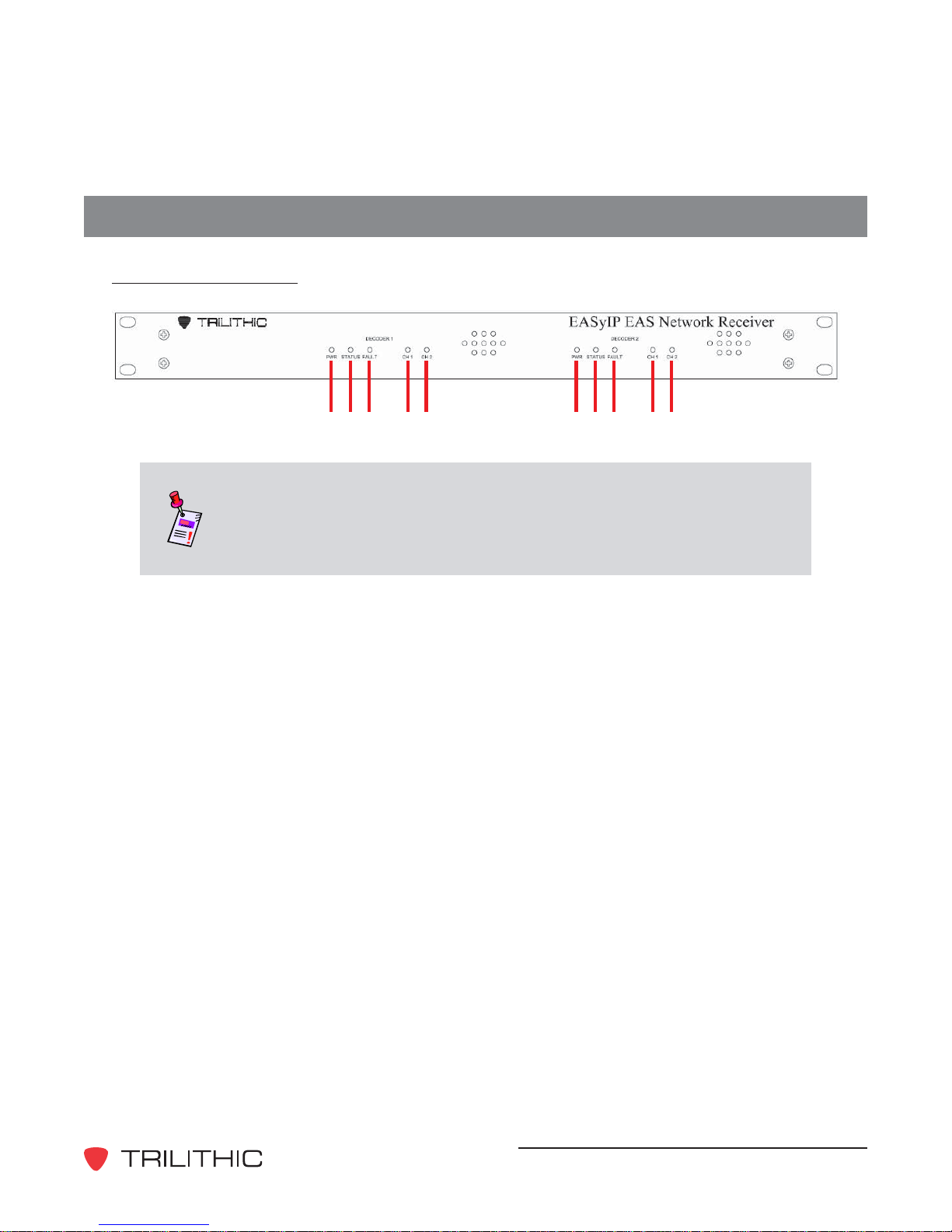
Front Panel View
A BC DE ABC DE
Note: The EAS Network Receiver chassis is capable of housing two
Network Receivers. This allows four radio or baseband audio inputs in a
single chassis. Each Network Receiver in a two unit chassis is
connected and configured separately .
The front panel of the EAS Network Receiver includes the following LEDs for DECODER 1
and DECODER 2:
A. PWR - This LED will illuminate when DC power is applied to the corresponding
Network Receiver.
B. STATUS - This LED will flash when the corresponding Network Receiver is functioning.
C. FAULT - This LED will illuminate or flash when there is a problem detected with the
corresponding Network Receiver.
D. CH1 - When Channel 1 is configured to use the radio tuner and the radio signal
strength is acceptable, this LED will illuminate. When Channel 1 is configured as an
audio input, this LED turns off when no audio is being received. The LED flashes when
EAS messages are being received.
E. CH2 - When Channel 2 is configured to use the radio tuner and the radio signal
strength is acceptable, this LED will illuminate. When Channel 2 is configured as an
audio input, this LED turns off when no audio is being received. The LED flashes when
EAS messages are being received.
EASy IP EAS Network Receiver - Operation Manual
11
Page 12
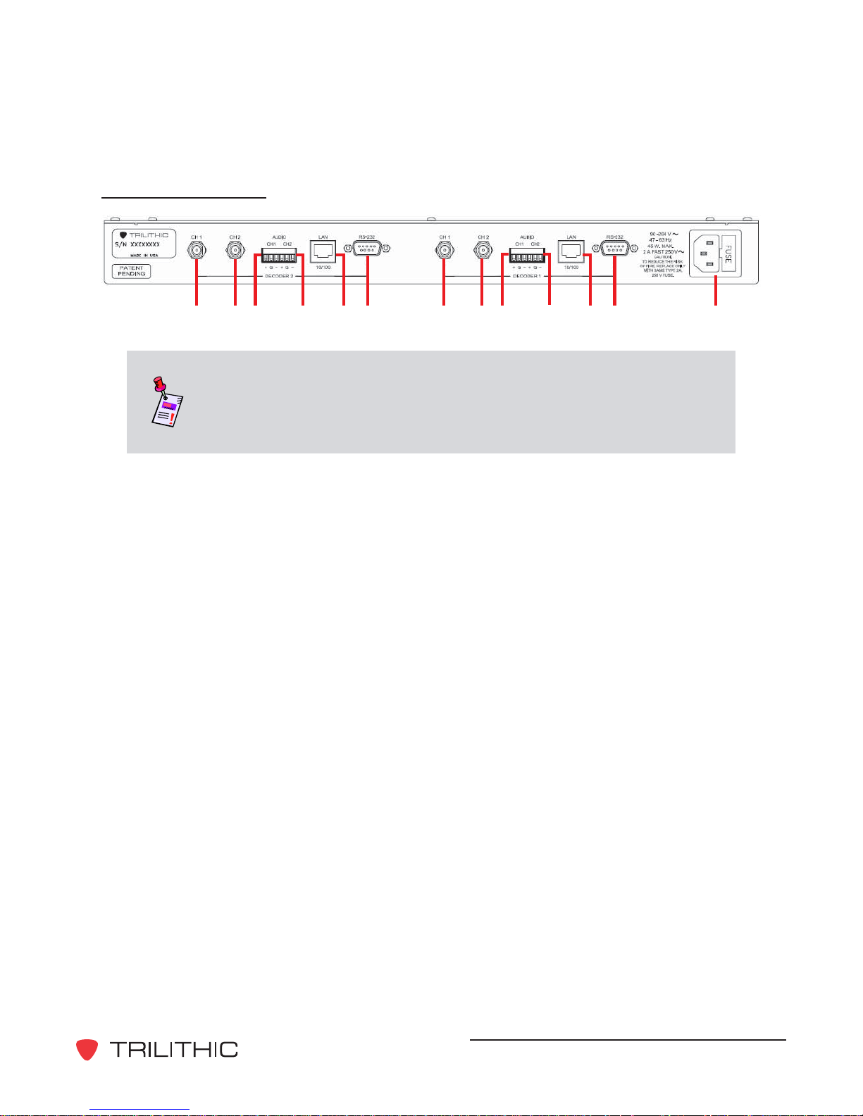
Rear Panel View
A BC DEF
A BC DEF G
Note: The EAS Network Receiver chassis is capable of housing two
Network Receivers. This allows four radio or baseband audio inputs in a
single chassis. Each Network Receiver in a two unit chassis is
connected and configured separately .
The rear panel of the EAS Network Receiver includes the following inputs/outputs for
DECODER 1 and DECODER 2:
A. CH1 - F-Connector antenna input for the channel 1 radio tuner (AM, FM, or NOAA)
B. CH2 - F-Connector antenna input for the channel 2 radio tuner (AM, FM, or NOAA)
C. AUDIO CH1 - Three-pin (positive, ground, negative) balanced audio input for the
channel 1 radio tuner
D. AUDIO CH2 - Three-pin (positive, ground, negative) balanced audio input for the
channel 2 radio tuner
E. LAN - RJ-45 connector for a 10/100 base-T Ethernet connection.
F. RS-232 - 9600 Baud serial interface for performing initial IP address configuration.
G. AC Power - US standard grounded power input with user-replaceable 2 Amp, 250 Volt
fast-blow (normal) fuse
EASy IP EAS Network Receiver - Operation Manual
12
Page 13

3. Installation
Prerequisites
Equipment and Software Required to Install the EAS Network Receiver:
• A computer running Microsoft Windows with an RS-232 port and HyperTerminal software is
required for initial configuration.
• A PC running Microsoft Windows with a network connection is required for configuring the
Network Receiver for EAS operation. The network must be able to allow communication
between the Network Receivers, encoder/decoders, and the configuration computer as
follows:
• 10/100 Base-T Ethernet interface, one for every two radio/audio inputs.
• Support outgoing UDP transmissions to encoder/decoders network.
• Supports incoming TCP connection from encoder/decoders network.
• Supports incoming TCP connection from configuration computer’s software.
3
!
• A static IP must be assigned for each of the Ethernet connections required.
• An appropriate location with a suitable antenna where monitored radio stations can be
received.
EASy IP EAS Network Receiver - Operation Manual
13
Page 14

Installing the EAS Network Receiver
The following section explains the procedure used to physically install the EAS Network Receiver .
In order to properly setup the Network Receiver the following steps must be completed in this
order. Do not skip any step s.
Note: DO NOT plug in the EAS Network Receiver’s power cord until
instructed to.
1. Mount the EAS Network Receiver in a standard 19 inch rack using four retaining screws.
2. Connect an antenna or audio input to each of the channels to be used. If you are using
baseband audio inputs, balanced audio is preferred. Only one source (radio or baseband
audio) can be used on a single channel.
3. Connect an Ethernet cable between the EAS Network Receiver and an active Ethernet port
on a switch or router. If the Network Receiver cont ains four radios, two Ethernet jacks will
be provided and both must be connected to the network.
4. Connect a serial cable (9 pin to 9 pin straight through) from the RS-232 connection of the
EAS Network Receiver to the serial port of the PC. (This port will be used for initial
configuration.)
5. Plug the EAS Network Receiver’s power cord into the AC power input.
EASy IP EAS Network Receiver - Operation Manual
14
Page 15
4. Initial Configuration
The factory default IP address for the EAS Network Receiver is “10.1.65.79”. By default it
monitors port 59910 for a connection from the EAS Network Receiver Management Software.
Those familiar with networking may be able to install the configuration software and configure the
instrument over the network, bypassing the following procedure.
Perform the following steps to complete the initial configuration of the EAS Network Receiver:
1. Connect the RS-232 cable (supplied) between the
Network Receiver’s RS-232 port and a PC with an
RS-232 port and HyperT erminal software.
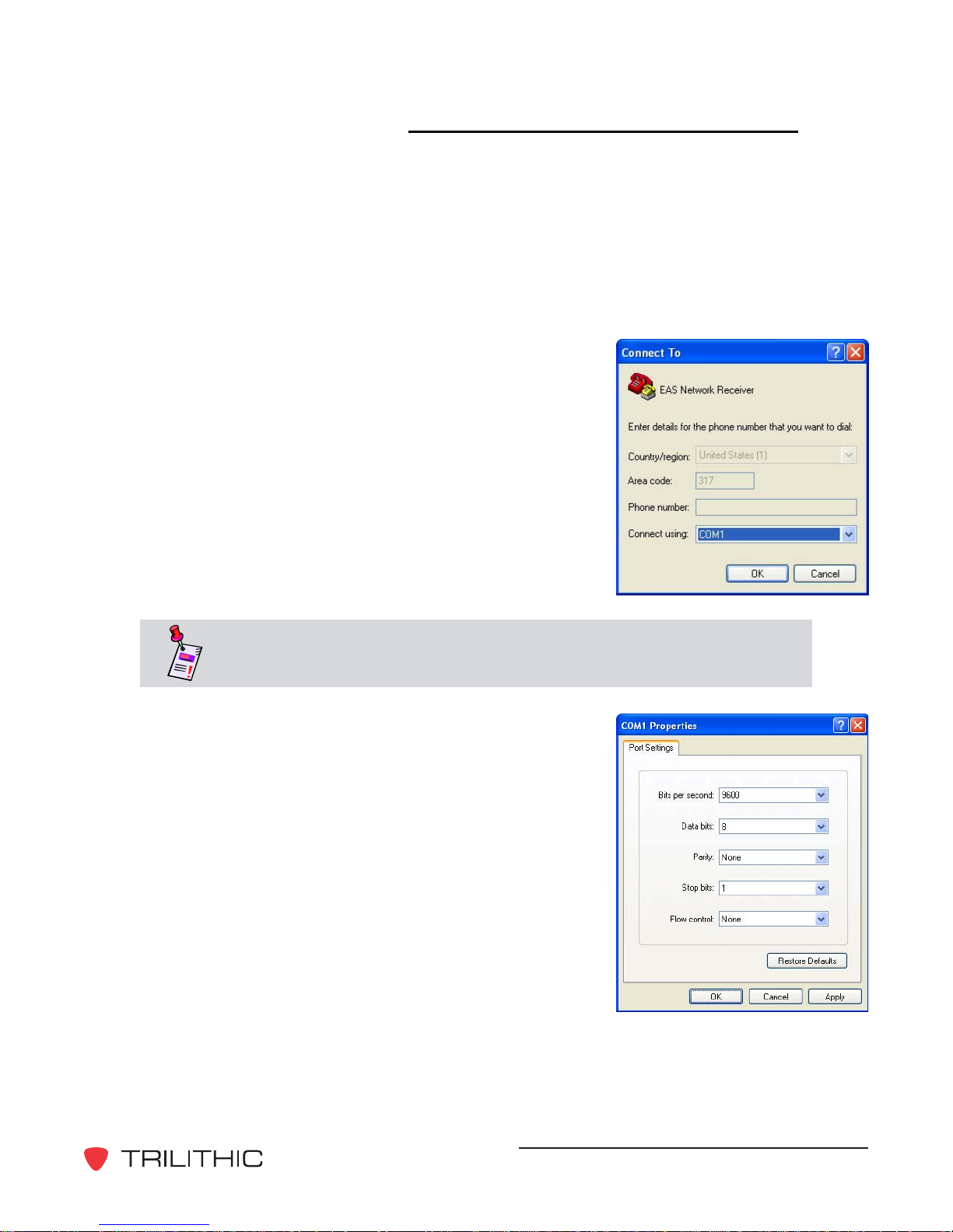
2. St art a HyperT erminal session for the serial port (COM 1)
that the Network Receiver has been connected to on a
laptop or PC.
4
!
Note: HyperT erminal is used for illustration purposes only , any terminal
emulator will work with this setup procedure.
3. Configure the port setting properties for the
HyperT erminal session as follows;
• Bits per second: 9600 Baud
• Data bits: 8
• Parity: None
• Stop bits: 1
• Flow control: None
EASy IP EAS Network Receiver - Operation Manual
15
Page 16

4. Select the OK button to connect to the Network Receiver , and then cycle the AC power
to the Network Receiver. Once the following text appears, press any key on the PC
keyboard before the countdown reaches zero.
5. The text “Press A to Accept the settings, or M to Modify?” will appear , press the M
button and then press the Return button.
6. The text “Reset configuration to default values (Y/N)?” will appear, press the N button
and then press the Return button.
EASy IP EAS Network Receiver - Operation Manual
16
Page 17

7. When prompted, enter the following settings:
• IP address for your network (i.e. 192.168.0.19) and press the Enter button.
• Subnet Mask IP address for your network (i.e. 255.255.255.0) and press the
Enter button.
• Gateway IP address for your network (i.e. 192.168.0.1) and press the Enter
button.
• The text “HTTP Server enabled. Disable it (Y/N)?” or “HTTP Server disabled.
Enable it (Y/N)?”, press the Y or N button and then press the Return button.
Note: The HTTP Server must be enabled to configure the EAS
Network Receiver using an Internet Web browser .
8. After the final entry , additional information will appear, including the port that the
software must use to connect to the Network Receiver over the Ethernet.
EASy IP EAS Network Receiver - Operation Manual
17
Page 18

5. Required Encoder/Decoder
5
!
Setup
Prior to accepting messages from the EAS Network Receiver , the encoder/decoder must be
configured for operation on the network. Refer to the encoder/decoder instructions to perform this
operation. A network path must be available for the EAS Network Receiver to initiate cont act with
the encoder/decoder over a UDP connection. In addition, the encoder/decoder must be able to
initiate a TCP connection to the Network Receiver over the Network Receiver’s configuration port
(default 59910).
The minimum software/firmware version for the encoder/decoder to support the Network Receiver
operation is version 6.50. Ensure that the encoder/decoder , the EASyNIC card, and the
configuration software have been upgraded. See your specific hardware or software Operation
Manual for more information on how upgrade your firmware and software.
Perform the following steps to configure your encoder/decoder:
1. St art the EASy PLUS Configuration Software and go to the Digital tab, Digital Config
sub-tab. In the Network Receiver UDP Port field, configure the UDP port that the Network
Receiver will use for initial contact. By default, the Network Receiver uses port 59912.
2. On the System tab, select the Program Configuration button and wait for the
configuration to complete.
3. Cycle the power to the encoder/decoder for the change to take affect.
Note: Changes to the network settings, including changes to ports
being monitored, require that the instrument be power cycled before
these changes will take affect.
Note: T o disable monitoring for Network Receivers, change the
Network Receiver UDP Port field to zero, program the configuration,
and then power cycle the encoder/decoder.
EASy IP EAS Network Receiver - Operation Manual
18
Page 19

6. Network Receiver
6
!
Management Program
Overview
Configuration of the EAS Network Receiver can be performed by using the EAS Network
Receiver Management Program as shown in this chapter or through an Internet Web browser . For
more information on how to configure your EAS Network Receiver through an Internet Web
browser, see Chapter 7: W eb Browser Configuration.
How to Install the Software
T o install the EAS Network Receiver Management Program, perform the following step s:
1. Depending on the operating system you are installing the program on, you may need to log
on as the local administrator.
Note: Check with your network or systems administrator if you’re not
sure about your current login account permissions.
2. Insert the software CD in the appropriate drive, if using a CD to install.
3. If you have Autorun enabled for the CD-ROM drive, the software setup program will st art
automatically . Otherwise, select the Start button then select Run, and type
[drive]:\Setup.exe, then select the OK button. (Substitute the appropriate drive path in the
command.)
Note: If you have a previous version of the EAS Network Receiver
Management Program installed on your system, you will be prompted to
un-install the software before proceeding with the installation of the new
software. For more information, see the How to Un-Install the Software
Section of this chapter.
EASy IP EAS Network Receiver - Operation Manual
19
Page 20

4. The “Welcome to the InstallShield Wizard for T rilithic EAS Network Receiver” screen
appears, select the Next > button to proceed to the next step of the installation wizard.
Note: T o cancel the inst allation of the software at any time during the
installation, select the Cancel button.
5. The “License Agreement” screen appears, select “I accept the terms of the license
agreement” radio button, and then select the Next > button to proceed to the next step of
the installation wizard or select the Cancel button to exit without installing.
EASy IP EAS Network Receiver - Operation Manual
20
Page 21

6. The “Destination Folder” screen appears, select the Next > button to accept the default
installation directory , or select the Change... button to change the installation directory and
then select the Next > button.
7. The “Ready to Install the Program” screen appears, select the Install button to proceed
with the installation.
EASy IP EAS Network Receiver - Operation Manual
21
Page 22

8. The “Installing T rilithic EAS Network Receiver” screen appears to indicate the status of the
software installation.
9. The “InstallShield Wizard Completed” screen appears, select the Finish button to confirm
the software installation. The software installation is now complete and can be started by
selecting the Desktop icon or by selecting the program from the Start menu.
EASy IP EAS Network Receiver - Operation Manual
22
Page 23

How to Un-Install the Software
T o un-install the EAS Network Receiver Management Program, perform the following step s:
1. Depending on the operating system you are installing the program on, you may need to log
on as the local administrator.
Note: Check with your network or systems administrator if you’re not
sure about your current login account permissions.
2. Select the Start button, then select the
Control Panel icon. The “Control Panel”
window will appear.
3. From the “Control Panel” window, select
the Add or Remove Programs icon. The
“Add or Remove Programs” window will
appear.
4. From the “Add or Remove Programs”
window , scroll through the listed of currently
installed programs and select Trilithic
EAS Network Receiver.
5. Select the Remove button to start the uninstall of the software.
EASy IP EAS Network Receiver - Operation Manual
23
Page 24

6. The text “Are you sure you want to remove
Trilithic EAS Network Receiver from your
computer?” will appear. Select the Yes
button to continue or select the No button
to quit the un-install of the software.
7. The software will begin to un-install. A
window will appear showing the progress
of the un-install. Once the un-install is
complete, the progress window will
disappear.
8. Y ou software is now sucessfully uninstalled. All program files as well as
shortcuts and links to the program that
were installed as part of the initial
installation should now be removed.
EASy IP EAS Network Receiver - Operation Manual
24
Page 25

System Tab
The System tab is primarily used to control the behavior of the EAS Network Receiver
Management Program itself. From the System tab is possible to:
• Maintain a database of several configurations that are usually used for several Network
Receivers.
• Control the IP address and port that the software uses to connect to the Network Receiver .
• Transfer configuration information to the Network Receiver .
• Import and export configuration files to and from the Management Program.
• Upgrade the system firmware.
EASy IP EAS Network Receiver - Operation Manual
25
Page 26

Managing Multiple Network Receiver Systems
Multiple configurations are supported to allow several EAS Network Receivers to be managed
from a single PC running the EAS Network Receiver Management Program. Use of this
feature keeps the configuration information and logs separated from other Network Receivers
managed from the same PC. If only one Network Receiver is being maintained, this feature
can be ignored. This feature is also useful for four channel systems that include two Network
Receivers.
Adding a New Network Receiver System
Perform the following steps to add a new Network Receiver system:
1. On the System tab of the software, select the Add System button.
2. The “Add a Network Receiver System” window will appear, enter a descriptive title
in the System Name field, and then select the ACCEPT button.
Note: Do not use the special characters “\”, “/”, “.”, “?”, “*”, “:”, and “;”
when creating a new system name, they are prohibited.
Note: When a new Network Receiver system is created, the contents of
the previously accessed Network Receiver system are copied into it.
EASy IP EAS Network Receiver - Operation Manual
26
Page 27

Selecting an Existing Network Receiver System
T o select a previously added Network Receiver system, on the System tab of the software,
select the Select System button, highlight the desired system name, and then select the
ACCEPT button.
Note: Always verify the correct system has been selected before
making changes to the configuration parameters.
Deleting an Existing Network Receiver System
T o delete a Network Receiver system that is no longer needed, on the System tab of the
software, select the Delete System button, highlight the desired system name, and then
select the ACCEPT button.
EASy IP EAS Network Receiver - Operation Manual
27
Page 28

Modifying the Name of an Existing Network Receiver System
T o modify the name of the selected Network Receiver system, on the System tab of the
software, select the Modify System button, enter the new Network Receiver system name,
and then select the ACCEPT button.
Configuring Your Network Receiver Communication Settings
T o configure the EAS Network Receiver Management Program to communicate with an EAS
Network Receiver, on the System tab of the software, enter the configured communication
parameters of the desired Network Receiver in the IP Address and Port Number fields.
EASy IP EAS Network Receiver - Operation Manual
28
Page 29

Programming a Configuration to Your Network Receiver
Before changes to the Network Receiver configuration can take affect, the configuration must
be sent to the Network Receiver.
Note: Before sending the selected configuration parameters to the
Network Receiver, you must configure your Network Receiver
communication settings for the desired Network Receiver.
T o send a configuration to the desired Network Receiver , on the System tab, select the
Program Configuration button. A status window should appear and disappear without
reporting any errors.
CAUTION: Changes to any parameters located on the Configuration
tab do not take affect until you select the RESET Hardware button from
the EAS Network Receiver Management Program or cycle the power to
your instrument.
EASy IP EAS Network Receiver - Operation Manual
29
Page 30

Retrieving a Configuration from Your Network Receiver
Y ou can load a Network Receiver’s configuration parameters into the EAS Network Receiver
Management Program:
• If more than one PC is used to manage the Network Receivers, this operation can be
performed before changes are made so that the PC configurations reflect the most
recent changes.
• During troubleshooting, load the configuration to verify that the software reflects the last
programmed configuration.
• If installing the EAS Network Receiver Management Program on an new PC,
configurations can be updated from the Network Receivers themselves.
Note: Before retrieving the selected configuration parameters from the
Network Receiver, you must configure your Network Receiver
communication settings for the desired Network Receiver.
T o load a Network Receiver’s configuration parameters into the EAS Network Receiver
Management Program, on the System tab, select the Retrieve Configuration button. A
status window should appear and disappear without reporting any errors.
Uploading Your PC Time to Your Network Receiver
The Network Receiver contains an internal clock that is used in the processing of logs. V erify
that your time zone and time are set correctly on the PC, and then send your PC’s time to your
Network Receiver by selecting the Upload PC Time button.
EASy IP EAS Network Receiver - Operation Manual
30
Page 31

Resetting/Rebooting Your Network Receiver
CAUTION: Changes to any parameters located on the Configuration
T ab do not take af fect until you select the RESET Hardware Button
from the EAS Network Receiver Management Program or cycle the
power to your instrument.
Note: When changing the IP Address or Configuration Port field on
the Configuration tab, the IP Address and Port Number fields on the
System tab should remain set to the old IP address and port number
until the RESET Hardware button has been selected.
Note: Before resetting/rebooting the Network Receiver, you must
configure your Network Receiver communication settings for the desired
Network Receiver.
T o reset the Network Receiver , on the System tab, select the RESET Hardware button. A
status window should appear and disappear without reporting any errors. The Network
Receiver may take as long as sixty seconds to complete a reset cycle.
If the value of the IP Address and/or Configuration Port field was changed on the
Configuration tab, update the IP Address and/or Port Number fields on the System tab
immediately after the successful reset.
EASy IP EAS Network Receiver - Operation Manual
31
Page 32

Importing and Exporting Your Network Receiver Configuration
Settings
T o export the configuration settings of your Network Receiver system, on the System tab of the
software, select the EXPORT Configuration button, enter the desired name of the
configuration, and then select the Save button.
T o import a configuration setting file that was previously exported, on the System tab of the
software, select the IMPORT Configuration button, select the desired configuration file, and
then select the Open button.
Upgrading Your Network Receiver Firmware
Perform the following steps to upgrade the firmware of your Network Receiver system:
1. On the System tab of the software, select
the Upgrade Firmware button. The “EAS
Network Receiver Upgrade Utility” screen
appears as shown in the graphic to the
right.
2. Select the CONTINUE button to program
the new firmware into your Network
Receiver or select the CANCEL button at
any time to exit without modifying your
Network Receiver firmware.
CAUTION: Do not stop the upgrade process or turn off the EAS
Network Receiver until the upgrade is complete. This can cause the
firmware to be corrupted and may require that the unit be sent into the
factory to be restored.
CAUTION: The upgrade process may damage configuration and logs.
Make sure to retrieve the configuration and logs before applying this
upgrade.
EASy IP EAS Network Receiver - Operation Manual
32
Page 33

3. On the next screen, enter the IP address of
the Network Receiver that you wish to
upgrade, and then select the CONTINUE
button.
4. The upgrade utility will verify what version
of firmware is installed in your Network
Receiver and notify you whether your
device needs a firmware upgrade. Select
the CONTINUE button to upgrade only the
files that are not current, otherwise, select
the Program All Files button to program
all Network Receiver files.
5. Once you have started the firmware
upgrade, the upgrade utility will show the
status of the upgrade. Once the upgrade is
complete, select the OKAY button.
6. It is recommended that you power-cycle
the EAS Network Receiver , making sure to
leave the power off for 5 seconds before
powering it back on. If you are not on-site,
the unit needs to be reset from the System
tab by selecting the RESET Hardware
button. For more information, see the
System Tab, Resetting/Rebooting Your
Network Receiver Section of this chapter.
7. After the Network Receiver has booted up,
verify that the configuration is correct, and
then from the System tab select the
Program Configuration button to upload
the configuration to the Network Receiver.
8. If SNTP is not enabled, from the System
tab select the Upload PC Time button to
set the correct system time.
EASy IP EAS Network Receiver - Operation Manual
33
Page 34

Configuration Tab
The Configuration tab is used to setup the EAS Network Receiver’s time and network
configuration.
CAUTION: Changes to any parameters located on the Configuration
T ab do not take af fect until you select the RESET Hardware Button
from the EAS Network Receiver Management Program or cycle the
power to your instrument. For more information, see the System Tab,
Resetting/Rebooting Your Network Receiver Section of this chapter .
EASy IP EAS Network Receiver - Operation Manual
34
Page 35

Time Settings
Perform the following steps to setup the time settings for your Network Receiver:
1. Select the down arrow next to the Time Zone drop-down box, and then highlight your
time zone from the list provided.
2. If you are using Simple Network Time Protocol (SNTP) to automatically adjust the
Network Receiver’s clock, select the Enable SNTP checkbox to enable this feature
and then:
• Enter the IP address of the SNTP server in the Primary SNTP Server field.
• Enter the IP address of the backup SNTP server (if applicable) in the
Secondary SNTP Server field.
• Use the up or down arrow button to choose from a sync time between 4 and 168
hours in the Sync Interval field.
CAUTION: Enabling SNTP and configuring invalid SNTP Servers can
have an adverse affect on the Network Receiver time.
EASy IP EAS Network Receiver - Operation Manual
35
Page 36

Network Settings
The EAS Network Receiver requires a static IP address assigned by your Network
Administrator . At a minimum, a valid IP address and subnet mask are required. If the EAS
Network Receiver, EAS Encoder/Decoder , or EAS Network Receiver Management Program
are not on the subnet, a valid gateway address (within the subnet) is required. Verify all
settings with your Network Administrator .
IP Address - Enter the value of the static IP address for the Network Receiver .
Subnet Mask - Enter the value of the subnet mask address for the Network Receiver’s
subnet.
Default Gateway - Enter the value of the gateway address for the subnet, or leave blank.
Host Name - Enter the name of the Network Receiver to be registered with the DNS
server(s), or leave blank.
Configuration Port - Enter the value of the TCP/IP port that will be used for both the EAS
Network Receiver Management Program and the EAS Encoder/Decoder to transfer data.
Enable Web Server - Select the checkbox to enable the Web access feature of the EAS
Network Receiver. This feature allows you to remotely access most configuration
parameters from a Web browser , locally or through the Internet.
EASy IP EAS Network Receiver - Operation Manual
36
Page 37

Audio Inputs Tab
The Audio Input s tab is used to choose radio stations or configure a baseband audio input to be
used for EAS monitoring. EAS sources are specified in St ate and Local EAS plans, not chosen
by the user . In addition to configuring EAS sources, the front panel speaker can be configured in
order to verify reception.
EASy IP EAS Network Receiver - Operation Manual
37
Page 38

Audio Input Channel Settings
Perform the following steps to setup the audio input channel settings for your Network
Receiver:
1. Select the down arrow next to the Select an Audio Input to Configure drop-down
box, and then highlight the desired channel (Channel
1 or Channel 2).
2. Select the External Audio radio button if the
selected channel is either not used, or is connected
to an audio source, otherwise select the Radio
Receiver radio button.
3. If the selected channel is an antenna input and you
have selected the Radio Receiver radio button
perform the following steps:
• Select the AM, FM, or NOAA radio button,
where NOAA is the National Weather Radio
band.
• If the station is a nearby , high-power radio
station, select the Local - High Signal
Strength checkbox.
• Select the correct radio frequency for your
selected radio band at the bottom of the
Audio Input Channel Settings area.
4. Select the Program Audio Settings button to set the configuration for the selected
channel and repeat for each audio input channel that needs configured.
EASy IP EAS Network Receiver - Operation Manual
38
Page 39

Speaker Settings
Perform the following steps to verify the audio input channel settings for your Network
Receiver:
1. Select the down arrow next to the Speaker Source drop-down
box and then highlight the desired channel (Channel 1 or
Channel 2).
2. Adjust the front panel speaker volume by adjusting the slider up
or down.
3. V erify the audio settings by selecting the Change Speaker
Source & V olume button. The front panel speaker should
contain clear audio from the selected channel. Some EAS
specific audio sources may not contain audio until an EAS
message is activated.
4. Repeat this procedure for each audio input channel that has
been configured. Af ter verifying the audio input channel
settings for you Network Receiver , set the Speaker Source
drop-down box to Internal to mute the front panel speaker .
EASy IP EAS Network Receiver - Operation Manual
39
Page 40

Encoder/Decoders Tab
The Encoder/Decoders tab is used to configure where EAS messages are delivered. The
Network Receiver forwards received EAS messages to a group of EAS Encoder/Decoders that
are included in the contact list. Up to eight EAS Encoder/Decoders can be activated (added to
the contact list) from a single EAS Network Receiver . This tab is provided to configure the
encoder/decoders that must be contacted with EAS alert messages.
CAUTION: Configuration changes to the EAS Network Receiver do not
take affect until you select the Program Configuration button from the
EAS Network Receiver Management Program. This will send the
currently displayed configuration parameters to the instrument and
should be the last configuration operation that is performed. For more
information, see System Tab, Programming Your Network Receiver
Configuration in this chapter.
EASy IP EAS Network Receiver - Operation Manual
40
Page 41

Adding a New Encoder/Decoder to the Contact List
Perform the following steps to add a new encoder/decoder to the contact list:
1. On the Encoder/Decoders tab of the software, enter the IP address of the encoder/
decoder that you wish to add in the IP Address field.
2. Use the up or down arrow button to choose a UDP port number of the selected
encoder/decoder uses to receive Network Receiver alerts in the UDP Port field. For
more information on how to set the UDP port number of an encoder/decoder , see
Chapter 5: Required Encoder/Decoder Setup.
3. Select the Add button to add the selected encoder/decoder to the list. The IP address
and UDP port of the new encoder/decoder will appear in the first available slot in the
contact list.
EASy IP EAS Network Receiver - Operation Manual
41
Page 42

Modify an Existing Encoder/Decoder in the Contact List
T o modify the IP address and UDP port number of an existing encoder/decoder, perform the
following steps:
1. On the Encoder/Decoders tab of the software, select the desired encoder/decoder
from the contact list. The selected encoder/decoder’s IP address and UDP port number
will automatically appear in the IP Address and UDP Port fields.
2. Enter the new IP address or UDP port number in the IP Address and UDP Port fields,
and then select the Modify button. The changes will be reflected in the contact list
below.
EASy IP EAS Network Receiver - Operation Manual
42
Page 43

Deleting an Existing Encoder/Decoder from the Contact List
T o delete an existing encoder/decoder from the contact list, on the Encoder/Decoders tab of
the software, select the desired encoder/decoder from the contact list, and then select the
Delete button. The changes will be reflected in the contact list below .
EASy IP EAS Network Receiver - Operation Manual
43
Page 44

Logs Tab
Log maintenance is not required on the Network Receiver, however it contains a diagnostic log
that may be used in troubleshooting the EAS system. These logs are not typically used in FCC
required files, as the encoder/decoders will maintain a log of messages received from Network
Receivers.
CAUTION: Logging stops when the log memory is full, therefore it is
recommended that the logs be erased every three to six months.
Word Wrap - Enable or disable the word-wrap function of the log display window .
PRINT - Print the currently displayed log to the Windows default printer.
SA VE - Save the currently displayed log to a text file.
Clear Log - Clear the information that is currently displayed in the log display window.
EASy IP EAS Network Receiver - Operation Manual
44
Page 45

Download Onboard Log - Connect to the selected Network Receiver and retrieve its log.
Once downloaded, the log information will be displayed in the log display window .
Erase Onboard Log - Connect to the selected Network Receiver and erase its onboard log.
Once erased, the log information that is displayed in the log display window will remain
unchanged.
Note: Before downloading or erasing the log from the Network
Receiver, you must configure your Network Receiver communication
settings for the desired Network Receiver .
EASy IP EAS Network Receiver - Operation Manual
45
Page 46

Utilities Tab
The Utilities tab is used to send an EAS test message. T o send a EAS test message, enter the
desired FIPS Code in the FIPS Code for T est field and then press the Send Test Message
button.
CAUTION: Pressing the Send T est Message button may cause
interruption of legitimate EAS messages as well as interruption of
subscriber programs, proceed with caution.
EASy IP EAS Network Receiver - Operation Manual
46
Page 47

7. Web Browser Configuration
7
!
Overview
Configuration of the EAS Network Receiver can be performed by using an Internet Web browser
as shown in this chapter or through the EAS Network Receiver Management Program. For more
information on how to configure your EAS Network Receiver through the EAS Network Receiver
Management Program, see Chapter 6: Network Receiver Management Program.
T o access the Main Page of the Internet W eb browser EAS Network Receiver Configuration;
• Enter the address http://XXX.XXX.XXX.XXX/index into the URL address bar of your
Internet Web browser . “XXX.XXX.XXX.XXX” denotes the configured IP address of your
EAS Network Receiver. The factory default IP address for the EAS Network Receiver is
“10.1.65.79”.
• Once you have entered the address above, press the Enter button on your keyboard, and
then the Main Page will appear as shown below .
T o access individual configuration parameter pages, select the corresponding hyperlink from the
Main Page. Y ou can return to the main page from any configuration parameter p age by selecting
the Main Page button.
EASy IP EAS Network Receiver - Operation Manual
47
Page 48

Time Configuration
The Time Configuration Page is used to configure the same settings that are described in
Chapter 6: Network Receiver Management Program, Configuration Tab, Time Settings.
Once you have completed the changes to your time settings, press the Program Time
Configuration button to program your EAS Network Receiver with the new settings.
T o program the internal clock of the Network Receiver , select the Set Clock button. The following
page will appear . T o set the proper system time, select the down arrow next to the appropriate
drop-down box . When you have finished making changes, select the Set Clock button to
program the internal clock of the Network Receiver.
EASy IP EAS Network Receiver - Operation Manual
48
Page 49

Network Configuration
The Network Configuration Page is used to configure the same settings that are described in
Chapter 6: Network Receiver Management Program, Configuration Tab, Network Settings.
Once you have completed your changes to the network configuration settings, press the Program
Network Configuration button to program your EAS Network Receiver with the new settings.
EASy IP EAS Network Receiver - Operation Manual
49
Page 50

Audio Input Configuration
The Audio Input Configuration Page is used to configure the audio input channel settings for
your Network Receiver.
T o change the type of audio input for Channel 1 and/or Channel 2, select External Audio, AM
Radio, FM Radio, or NOAA Radio button.
Note: The button that corresponds to the current audio input setting will
not be displayed.
Note: T o edit the current audio input settings, select the Edit <input
type> Settings button. The corresponding settings page will be
displayed, you can then configure your settings as described in Chapter
6: Network Receiver Management Program, Audio Inputs Tab, Audio
Input Channel Settings.
EASy IP EAS Network Receiver - Operation Manual
50
Page 51

If the selected channel is External Audio and you have selected the AM Radio, FM Radio, or
NOAA Radio button or you have selected the Edit <input type> Settings button, the
corresponding settings page will be displayed as shown below . These pages are used to
configure the same settings that are described in Chapter 6: Network Receiver Management
Program, Audio Inputs Tab, Audio Input Channel Settings. Once you have finished making
configuration changes, select the OK button to save your changes and return to the Audio Input
Configuration page or select the Cancel button to discard your changes and return to the Audio
Input Configuration page.
If the selected channel is AM Radio, FM Radio, or NOAA Radio and you have selected the
External Audio button, the corresponding settings page will be displayed as shown below. To
switch the audio channel to External Audio, select the OK button to save your changes and return
to the Audio Input Configuration page or select the Cancel button to discard your changes and
return to the Audio Input Configuration page.
EASy IP EAS Network Receiver - Operation Manual
51
Page 52

Encoder/Decoders Configuration
The Encoder/Decoders Configuration Page is used to configure the encoder/decoder settings
for your Network Receiver .
T o add a new encoder/decoder to the contact list, enter the IP Address and UDP Port of the
selected encoder/decoder in the corresponding field. T o delete an existing encoder/decoder from
the contact list, delete the IP Address and UDP Port of the desired encoder/decoder .
Once you have completed your changes to the encoder/decoders configuration settings, press the
Program Network Configuration button to program your EAS Network Receiver with the new
settings.
EASy IP EAS Network Receiver - Operation Manual
52
Page 53

Message Log
The Message Log Page is used to view a diagnostic log that may be used in troubleshooting the
EAS system. These logs are not typically used in FCC required files, as the encoder/decoders will
maintain a log of messages received from Network Receivers.
Select the Delete Log button to delete the diagnostic log or select the Main Page button to return
to the Main Page.
EASy IP EAS Network Receiver - Operation Manual
53
Page 54

System Actions
The System Actions Page is used to reset the Network Receiver and send EAS test messages.
Select the Reset button to restart the Network Receiver .
To send a EAS test message, enter the desired FIPS Code in the County Code field and then
press the Test button.
CAUTION: Pressing the Send T est Message button may cause
interruption of legitimate EAS messages as well as interruption of
subscriber programs, proceed with caution.
EASy IP EAS Network Receiver - Operation Manual
54
Page 55

8. EAS Network Receiver
Deployment
8
!
HEADEND
ASI Status GigE Enet
12345678
SEM
ASI Status GigE Enet
12345678
SEM
ASI Status GigE Enet
12345678
SEM
ASI Status GigE Enet
12345678
SEM
ASI Status GigE Enet
12345678
SEM
ASI Status GigE Enet
12345678
SEM
ASI Status GigE Enet
12345678
SEM
ASI Status GigE Enet
12345678
SEM
Ethernet
TRILITHIC EASyPLUS EAS/
IPTV Encoder/Decoder
AM
FM
ASI
12312
Monitor
Port
ASI
12312
Monitor
Port
ASI
12312
Monitor
Port
ASI
12312
Monitor
Port
ASI
12312
Monitor
Port
ASI
12312
Monitor
Port
ASI
12312
Monitor
Port
ASI
12312
Monitor
Port
NOAA
Inbound remote EAS Event
captures from Network
Receiver via TCP/IP
Outbound EAS Events to
subscribers DTV and settops,
and HFC/IPTV plant
equipment
Municipal
Baseband
Channel
n
u
o
b
n
c
I
S
A
E
e
N
t
o
m
m
o
r
e
f
r
v
s
r
d
e
e
r
v
u
i
t
e
p
c
a
e
R
Digital/Optical
Network
AM
t
n
e
v
k
E
r
o
w
P
t
I
/
e
CP
T
a
i
V
T
P
I
/
C
F
H
rk
o
w
t
e
N
EASyIP EAS Network Receiver
Ethernet
NOAAFM
HUB
Greenwood
County
HFC/IPTV
Cloud
Network
More Di s tant
Counties
Cumberland
AM
County
NOAAFM
HF
Network
C
/IPTV
EASyIP EAS Network
Receivers
Arrowwood
County
I
n
b
o
u
n
d
r
e
ca
m
p
o
t
u
t
e
r
e
E
s
R
e
c
A
f
S
r
o
m
e
i
v
e
E
ve
N
n
e
r
vi
a
t
t
w
o
r
k
T
C
P
/
I
P
EASyIP EAS Network Receiver
Ethernet
HUB
EASy IP EAS Network Receiver - Operation Manual
55
Page 56

9. Specifications
Mechanical:
Enclosure Dimensions: 1U - 19” rack mount
General: Accommodates 1 or 2 EAS Network Receiver boards (allowing for 4
EAS monitoring ports
Front Panel: Speaker (per board assembly; 2 radio channels per board)
Power, S tatus, Fault, Channel 1 & Channel 2 activity indicators (per
board)
Back Panel: AC power input
1 - RS-232 serial port on DB9 connector (per board)
1 - 10/100 Base-T Ethernet port on RJ-45 jack (per board)
2 - 600 Ohm balanced baseband audio inputs on 6 pin modular screw
terminal plug (per board)
2 - 75 Ohm antenna inputs on F connectors for internal radio receivers
(per board)
Communications: 1 - RS-232C serial port available on a DB9 connector
1 - 10/100 Base-T Ethernet port available on a RJ-45 jack
Supported network protocols: ARP, RARP, PING , UDP , TCP/IP, FTP ,
HTTP, SNTP and SNMP will be supported in a later firmware revision;
Spring 2008.
Processing & Memory: 32 bit RISC processor
Audio DSP
32 Mb RAM
32 Mb FLASH (nonvolatile)
RTC (real-time clock) with battery backup
Firmware upgrades are accomplished via FTP across the 10/100
Base-T Ethernet port.
Maintains an onboard nonvolatile log of all system activity (maximum
1 Mb), log entries include: receive EAS, EAS decode status, deliver
EAS, errors, etc.
Indicators: Power, st atus, fault, Channel 1 and Channel 2 activity indicators
available on the front panel.
Speaker is available on front panel to monitor audio/radio input s,
includes volume control.
!
9
EASy IP EAS Network Receiver - Operation Manual
56
Page 57

Audio:
General: 2 (4) audio inputs are monitored for EAS messages.
4 minutes of audio storage is provided for each input to store EAS
audio messages.
All audio inputs have AGC.
Each audio input is selectable as external baseband audio or radio
receiver.
Baseband audio inputs: balanced, 600 Ohm, modular screw terminal
plugs.
Internal radio receivers: 2 (4) internal radio receivers, selectable as
AM, FM, or NOAA.
75 Ohm F type connectors for the antenna inputs.
In-line pad to decrease input signal strength.
Minimum RF Input: AM 25 dBµV , FM 8 dBµV, NOAA 25 dBµV
Maximum RF Input: 60 dBµV
Frequency Range: AM 520 - 1720 KHz, FM 87.5 - 108 MHz, NOAA 162.4 - 162.55 MHz
EASy IP EAS Network Receiver - Operation Manual
57
Page 58

Warranty Information
Trilithic, Inc. warrants that each p art of this product will be free from defects in materials and
workmanship, under normal use, operating conditions and service for a period of two (2) years
from date of delivery . Trilithic, Inc.’ s obligation under this Warranty shall be limited, at T rilithic,
Inc.’s sole option, to replacing the product, or to replacing or repairing any defective part, F.O.B.
Indianapolis, Indiana; provided that the Buyer shall give Trilithic, Inc. written notice.
Batteries are not included or covered by this Warranty .
The remedy set forth herein shall be the only remedy available to the Buyer under this Warranty
and in no event shall Trilithic, Inc. be liable for incident al or consequential damages for any alleged
breach of this Warranty . This W arranty shall not apply to any part of the product which, without fault
of Trilithic, Inc., has been subject to alteration, failure caused by a p art not supplied by Trilithic, Inc.,
accident, fire or other casualty , negligence or misuse, or to any cause whatsoever other than as a
result of a defect.
Except for the warranty and exclusions set forth above, and the warranties, if any , available to the
Buyer from those who supply Trilithic, Inc., there are no warranties, expressed or implied (including
without limitation, any implied warranties of merchantability of fitness), with respect to the
condition of the product or its suitability for any use intended for it by the Buyer or by the purchaser
from the Buyer.
EASy IP EAS Network Receiver - Operation Manual
58
Page 59

P/N 0010210021 12/07 Made in U.S.A.
Trilithic, Inc.
9710 Park Davis Drive
Indianapolis, IN 46235
(317) 895-3600
(800) 344-2412
 Loading...