

Page 1

innovative technology to keep you a step ahead
Copyright © 2017 Trilithic, Inc. All Rights Reserved - 122117-REV1
Specications are subject to change without notice. Please contact your sales representative for further information.
Advanced Installation Meter 2
Operation Manual
Page 2

Putting Innovation Within Reach
Product innovation at Trilithic has always been characterized by one thing: it’s practical. It
makes life easier for customers. It’s the natural result of listening to them. That philosophy
has been the driving force behind the company’s growth from its beginnings as a two-man
engineering team in 1986 to its current position as a global manufacturer with more than 130
employees.
A privately held company, Trilithic broadened its original RF and microwave component product
line by acquiring lters manufacturer Cir-Q-Tel and instruments manufacturer Texscan, adding
broadband solutions to the product line. The company also expanded operations to Thailand in
2001, to meet increasing demand for its products in the growing markets of Asia.
As new communications applications continue to emerge, part of Trilithic’s business has
evolved into managing change—helping customers respond quickly to market opportunities
with innovative technology and individualized solutions. But the core value of Trilithic’s
business approach—listening to customers—hasn’t changed. Keeping that focus intact will
help provide better products in the long run and ensure continued growth for decades to come.
AIM 2 Operation Manual
Page 2
Page 3

Table of Contents
Chapter 1 .............................................................................................................. 7
General Information ..................................................................................................................7
Where to Get Technical Support
Warranty
Return Policy
How this Manual is Organized
Conventions Used in this Manual.........................................................................................11
Precautions
.................................................................................................................................8
..........................................................................................................................8
..........................................................................................................................11
Chapter 2 ............................................................................................................ 13
Introduction ..............................................................................................................................13
What is the AIM?
Overview
..................................................................................................................13
.........................................................................................................................13
Chapter 3 ............................................................................................................ 15
Getting to Know Your Meter ...................................................................................................15
Overview
Equipment Supplied with the AIM
Replacement Parts...............................................................................................................15
A Guided Tour of Your AIM
Front View .......................................................................................................................16
Right Side View
Back View .......................................................................................................................17
Powering Your Meter
Power-On........................................................................................................................18
Standby Mode.................................................................................................................18
Restart
Power-Off
Hard Reset......................................................................................................................19
Power Management........................................................................................................20
Battery Charging
Battery Replacement ......................................................................................................22
Display and Navigation
Display Screen................................................................................................................24
Navigation
HOME Screen.................................................................................................................26
Capturing a Screenshot ..................................................................................................26
..............................................................................................................................15
..............................................................................................................17
............................................................................................................18
............................................................................................................................18
........................................................................................................................19
.............................................................................................................21
........................................................................................................24
.......................................................................................................................25
............................................................................................7
...............................................................................................9
........................................................................................15
...................................................................................................16
AIM 2 Operation Manual
Page 3
Page 4

Chapter 4 ............................................................................................................ 27
Setting Up the Meter ...............................................................................................................27
Overview
Entering Registration Information.........................................................................................28
Setting up the Wi-Fi Connection
Setting up the Bluetooth Connection....................................................................................32
Setting up the Ethernet Connection
IP Settings ......................................................................................................................36
IP Address ......................................................................................................................37
Gateway, Netmask, and DNS Addresses .......................................................................37
Changing the Volume Settings
Changing the Display Contrast or Brightness
Changing the Time and Date Settings
Changing the Automatic Timer Settings
..............................................................................................................................27
..........................................................................................30
.....................................................................................35
.............................................................................................38
......................................................................39
.................................................................................40
...............................................................................42
Chapter 5 ............................................................................................................ 45
Setting Up a Job ......................................................................................................................45
Overview
Starting a Job
Modifying the Setup for a Job
Notes ..............................................................................................................................47
Dish Type ........................................................................................................................48
Reverse / International LNB............................................................................................48
Switch Type ....................................................................................................................49
Zip Code .........................................................................................................................49
..............................................................................................................................45
.......................................................................................................................46
..............................................................................................47
Chapter 6 ............................................................................................................ 51
Installing an ODU .....................................................................................................................51
Overview
Aligning the ODU ............................................................................................................51
ODU Installation Tasks ...................................................................................................52
Task A. Installation Setup................................................................................................53
Task B. Coarse Azimuth Adjustment ...............................................................................54
Task C. Coarse Elevation Adjustment.............................................................................54
Task D. Tilt Adjustment (95°, 3-LNB, Slimline-5, and Slimline-5S (SWiM) ODUs Only) .55
Task E. Fine Elevation Adjustment (Slimline ODUs Only) ..............................................55
Task F. Fine Azimuth Adjustment (Slimline ODUs Only) .................................................57
Performing EIV Following ODU Installation ....................................................................58
AIM 2 Operation Manual
Page 4
..............................................................................................................................51
Page 5

Chapter 7 ............................................................................................................ 61
Performing EIV.........................................................................................................................61
Overview
..............................................................................................................................61
Chapter 8 ............................................................................................................ 67
Performing Other Network Tests ...........................................................................................67
Overview
Using Guided Mode
Performing EIV Plus
Performing a Satellite Tune Test
Performing a Transponder Survey
Performing a Cable Resistance Test
Performing an In-Line Test
Performing a SWiM LF Power Test
Performing a SWiM Channel Assignments Test
..............................................................................................................................67
.............................................................................................................68
.............................................................................................................73
..........................................................................................78
.......................................................................................81
....................................................................................85
...................................................................................................87
......................................................................................89
..................................................................90
Chapter 9 ............................................................................................................ 93
Managing Records ..................................................................................................................93
Overview
Understanding Records
Viewing Records
Deleting Records..................................................................................................................97
Transferring Records
Transferring records from the AIM to a USB ash drive ...............................................100
Transferring records from a USB ash drive to the AIM ...............................................103
..............................................................................................................................93
.......................................................................................................93
..................................................................................................................94
..........................................................................................................100
Chapter 10 ........................................................................................................ 105
Updating the Meter ................................................................................................................105
Overview
Updating the Firmware
Update Firmware from the Internet ...............................................................................106
Update Firmware from a USB Flash Drive ...................................................................106
............................................................................................................................105
.......................................................................................................105
Chapter 11 ........................................................................................................ 107
Appendix ................................................................................................................................107
Specications
.....................................................................................................................107
AIM 2 Operation Manual
Page 5
Page 6

THIS PAGE LEFT INTENTIONALLY BLANK
AIM 2 Operation Manual
Page 6
Page 7

Chapter 1
General Information
Where to Get Technical Support
When you need instructions for using the AIM, your rst resource for help is this manual. If you
cannot nd the information you need, you can:
• Go to the DIRECTV Satellite Installer website or other websites provided by DIRECTV.
DIRECTV websites contain product specications and information, tips, release
information, marketing information, Frequently Asked Questions (FAQs), bulletins and
other technical information. You can also check these websites for product updates.
Contact Solid Signal at 877.312.4547 or email info@solidsignal.com.
•
For quicker support response when calling or sending e-mail, please provide the following
information:
• Your name and your company name
• The technical point of contact (name, phone number, e-mail)
• The AIM serial number, rmware and hardware version numbers
• A detailed description of the problem you are having, including any error or information
messages
AIM 2 Operation Manual
Page 7
Page 8

Warranty
Trilithic, Inc. warrants that each part of this product will be free from defects in materials and
workmanship, under normal use, operating conditions and service, for a period of fteen (15)
months from date of shipment. The obligation of Trilithic, Inc. under this warranty shall be
limited, at the sole option of Trilithic, Inc., to replacing the product or repairing any defective
part.
This warranty and the rights created hereunder are neither transferable nor assignable without
the prior written consent of Trilithic, Inc.
Replaceable items such as batteries, soft cases, and input connectors, etc. are not included
nor covered by this warranty.
The remedy set forth herein shall be the only remedy available to the Buyer under this
warranty, and, in no event, shall Trilithic, Inc. be liable for incidental or consequential damages
for any alleged breach of this warranty. This warranty shall not apply to any part of the product
that, without fault of Trilithic, Inc., has been subsequently altered or modied, nor shall it apply
to any failure caused by a part not supplied by Trilithic, Inc. and subsequently attached to or
incorporated into the product. This warranty shall not apply to any damage caused by accident,
re, or other casualty, negligence, misuse, or to any cause whatsoever other than as a result of
a defect directly attributable to Trilithic, Inc.
Except for the warranty and exclusions set forth above, and the warranties, if any, available
to the buyer from those who supply Trilithic, Inc., there are no warranties, express or implied
(including, without limitation, any implied warranty or warranty of merchantability of tness for a
particular purpose), with respect to the condition of the product.
Return Policy
Before returning a product for service, please call Solid Signal at 877.312.4547 for further
instructions.
AIM 2 Operation Manual
Page 8
Page 9

How this Manual is Organized
This manual is divided into the following chapters:
• Chapter 1: General Information provides Trilithic contact information and describes
how this operation manual is structured.
• Chapter 2: Introduction introduces what the AIM is and what it does. This chapter
discusses the practical application, connections and controls of the AIM. Finally, this
chapter discusses the battery of the AIM and how to update your rmware.
• Chapter 3: Getting to Know Your Meter describes a brief overview of the features,
buttons, and controls of the AIM.
• Chapter 4: Setting Up the Meter describes how to congure and operate the AIM. This
chapter provides instructions for entering registration information, as well as setting the
meter’s volume, display contrast and brightness, time limits for power-saving features,
and date and time.
• Chapter 5: Setting Up a Job describes the steps needed to set up the information for
the installation job. This chapter provides instructions for entering the account number,
selecting the ODU type, selecting the switch type, and entering the zip code.Chapter 5,
“Appendix” shows the technical specications of the AIM as well as any error codes that
may appear on the display screen of the AIM.
• Chapter 6: Installing an ODU describes the steps needed for aligning and performing
follow-up Extended Installation Verication (EIV) for each ODU. This chapter provides
instructions for how to complete these processes using the AIM.
• Chapter 7: Performing EIV describes the steps needed to perform Extended
Installation Verication (EIV) at selected points in the distribution network to quickly
conrm that the installation is satisfactory for all supported orbital slots. EIV is an easy
way to pinpoint any potential problems with the installation. This chapter provides
instructions for performing EIV at the ODU and other locations in the distribution
network.
• Chapter 8: Performing Other Network Tests describes the steps to The AIM stores
records for tests performed on the AIM, as well as screenshots. This chapter provides
instructions for how to view records, delete records, and transfer records to or from the
AIM using a USB ash drive.
AIM 2 Operation Manual
Page 9
Page 10

• Chapter 9: Managing Records describes the steps needed to to view records, delete
records, and transfer records to or from the AIM using a USB ash drive.
• Chapter 10: Updating the Meter describes the steps needed for updating the meter’s
rmware.
• Chapter 11: Appendix shows the technical specications of the AIM.
AIM 2 Operation Manual
Page 10
Page 11
Conventions Used in this Manual
This manual has several standardized conventions for presenting information:
• Connections, menus, menu options, and user-entered text and commands appear in
bold.
• Section names, web, and e-mail addresses appear in italics.
A NOTE is information that will be of assistance to you related
to the current step or procedure.
A CAUTION alerts you to any condition that could cause a
mechanical failure or potential loss of data.
A WARNING alerts you to any condition that could cause
personal injury.
Precautions
Do not use the AIM in any manner not recommended by the
manufacturer.
A strong electromagnetic eld may affect the measurement
accuracy of the AIM.
Use only the battery charger supplied with the AIM.
All spent batteries should be disposed of according to local
laws and guidelines.
AIM 2 Operation Manual
Page 11
Page 12

THIS PAGE LEFT INTENTIONALLY BLANK
AIM 2 Operation Manual
Page 12
Page 13
What is the AIM?
Overview
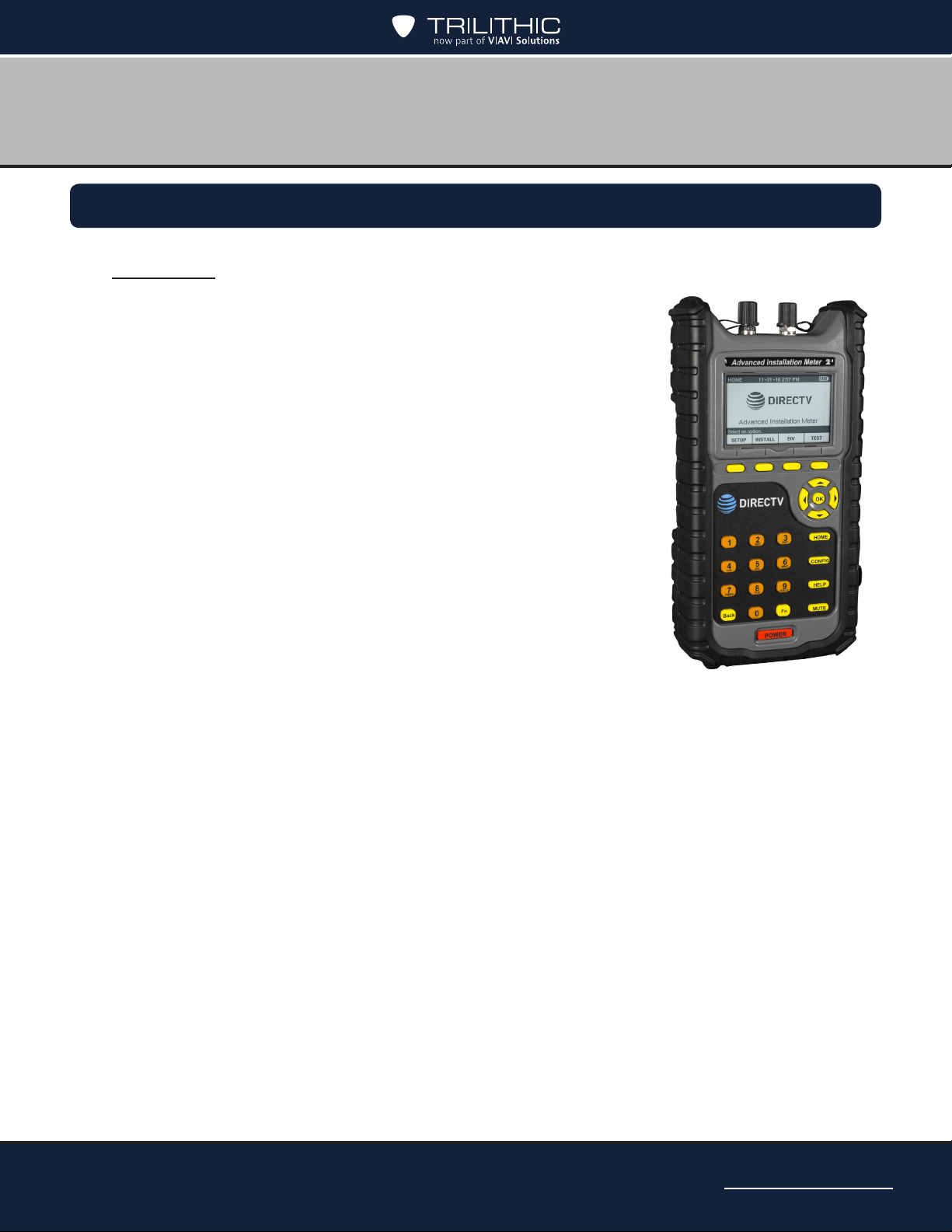
Congratulations on your new Advanced Installation Meter (AIM)
2! The AIM 2 was developed in collaboration with DIRECTV to
provide customized features for installing and troubleshooting
DIRECTV satellite receiver systems.
The AIM is a rugged meter suitable for both indoor and outdoor
use. When fully charged, the AIM can be used to install satellite
receiver systems in approximately six single-family homes on
a single charge. Both an AC power adapter and a convenient
vehicle power adapter are provided for charging the meter. The
carrying case protects the meter and its accessories during
transport and storage.
Chapter 2
Introduction
The AIM’s large display and keypad make it easy to navigate to
the features you need. On-screen directions guide you through
ODU installation, Extended Installation Verication (EIV), and
other test processes.
The AIM lets you track information for each account, including
account settings and test results. You can also transfer this
information from the meter to a PC using a USB ash drive.
New Wi-Fi, Bluetooth, and Ethernet connectivity provide for easier rmware updates and
report uploads, as well as through the USB port.
AIM 2 Operation Manual
Page 13
Page 14

THIS PAGE LEFT INTENTIONALLY BLANK
AIM 2 Operation Manual
Page 14
Page 15

Chapter 3
Getting to Know Your Meter
Overview
Before using your instrument, take a few minutes to familiarize yourself with the instrument,
its basic conventions, and its navigational tools. This section provides a brief overview of the
instrument’s features, buttons, and controls.
Equipment Supplied with the AIM
The AIM comes with the following:
• AIM meter
• Carrying case (with shoulder strap and hand strap)
• 100 – 240 VAC power adapter
• 12 VDC vehicle power adapter
• 25 Ω cable test load
• 2 GB USB ash drive (containing AIM Operator Manual)
Replacement Parts
The following replacement parts are available for the AIM:
Part Number Description
2131596000 Carrying case (with shoulder strap and storage pocket)
0610177000 100 – 240 VAC power adapter
2072097000B 12 VDC vehicle power adapter
0090070000 Battery pack
0200690000 “F” connector
2011379000 25 Ω cable test load
0930157003 2 GB USB flash drive (containing AIM Operator Manual)
AIM 2 Operation Manual
Page 15
Page 16
A Guided Tour of Your AIM
789
6
4
312
5
13
11
10
12
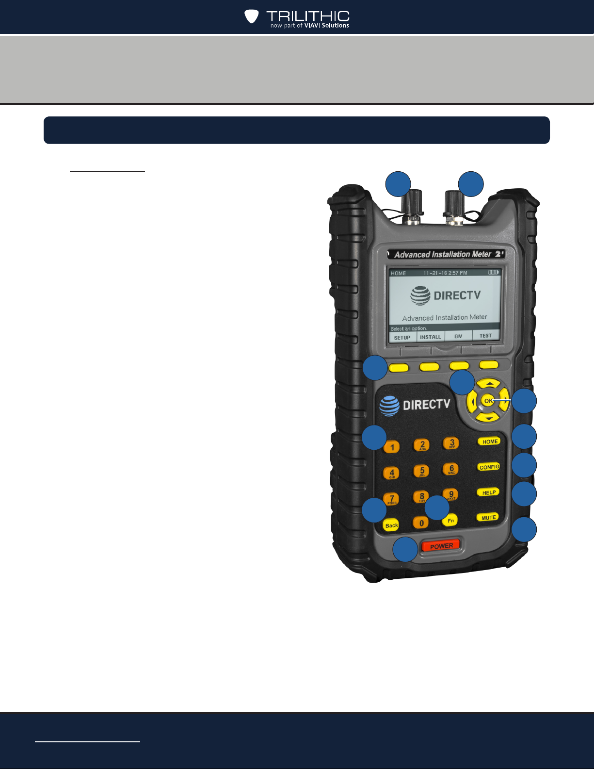
Front View
1. IRD F Connector
2. ODU F Connector
3. Softkeys – Select options that correspond
to the onscreen labels above
4. Arrow buttons – Navigate up and down to
select an option in a list, as well as right or
left when entering information
5. OK button – Selects the option highlighted
on the screen
6. Alphanumeric buttons – Enter text or
select a numbered list option
7. Back button – Go back to the previous
screen
8. Function button – Quickly change the
display contrast, display brightness,
volume, enable Rain Mode, and capture
screenshots
9. Power button – Turn on and off the meter
(with a long press) or backlight (with a quick
press)
10. HOME button – Displays the HOME screen
11. CONFIG button – View, delete and transfer
records, change meter settings, and
upgrade the meter’s rmware.
12. HELP button – Displays instructions to help
you complete the task being performed
13. MUTE button – Turns on and off the sound
on the meter
AIM 2 Operation Manual
Page 16
Page 17
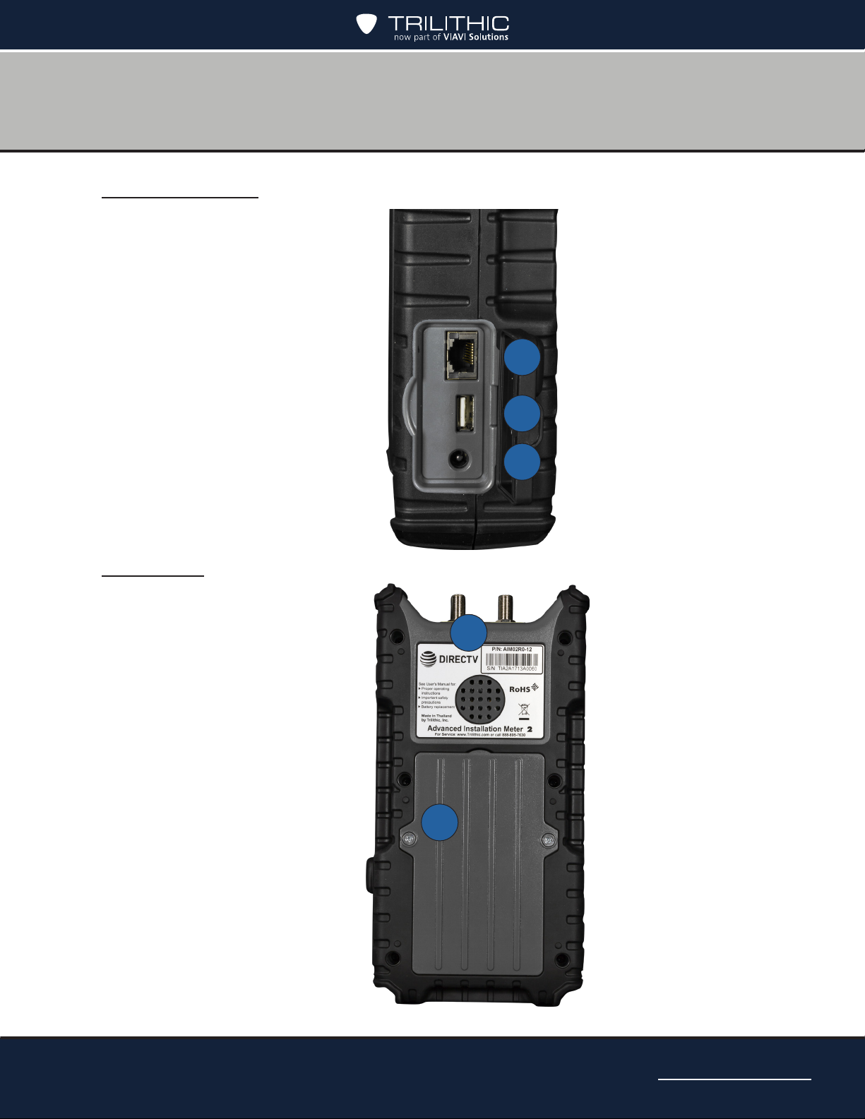
Right Side View
3
1
2
1
2
1. Gigabit Ethernet Port
2. USB 2.0 Port (Type A)
3. DC Charge Port
Back View
1. Serial number
2. Battery door
AIM 2 Operation Manual
Page 17
Page 18
Powering Your Meter
Power-On
To turn on the AIM, press and hold the POWER button until the backlight turns on and
the meter sounds a tone. The meter turns on, briey displays a splash screen, and then
displays the HOME screen.
To start a job, press SETUP and follow the instructions in “Starting a Job” in Chapter 5.
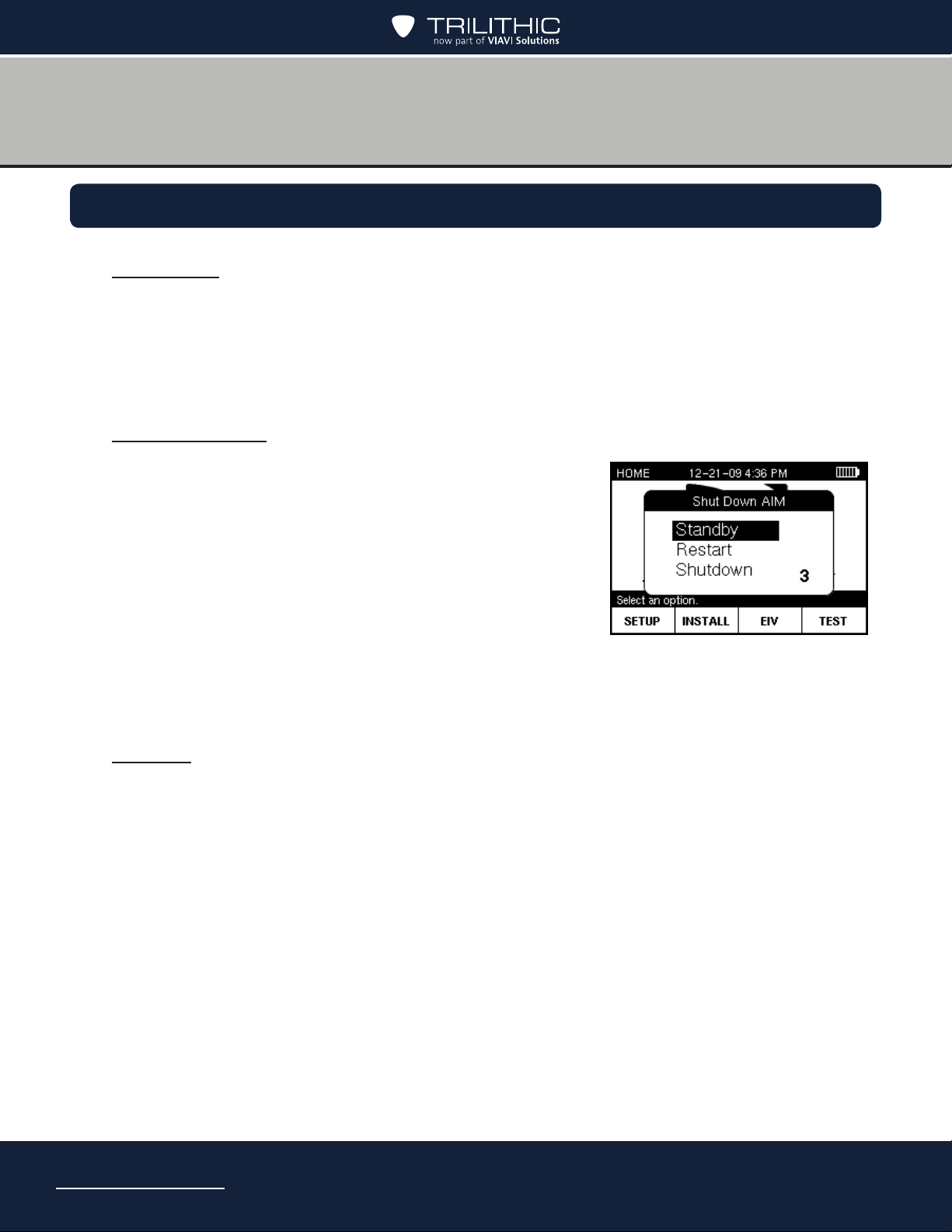
Standby Mode
You can place your AIM in a power-saving state called
Standby mode. Standby mode lets you turn off the AIM
display and other features to extend the charge of the
battery. You can quickly exit Standby mode and resume
working on the screen where you left off.
Press and hold the POWER button until the SHUT DOWN
AIM screen appears.
Use the up/down arrow buttons to highlight Standby and
press OK. The meter enters Standby mode.
To exit Standby mode, press the POWER button.
Restart
Press and hold the POWER button until the SHUT DOWN AIM screen appears.
Use the up/down arrow buttons to highlight Restart and press OK. The meter turns off and
restarts.
AIM 2 Operation Manual
Page 18
Page 19
Power-Off
Press and hold the POWER button until the SHUT DOWN AIM screen appears.
Use the up/down arrow buttons to highlight Shutdown and press OK. The meter turns off.
Hard Reset
If the AIM is unresponsive to button presses, perform a hard reset.
Press and hold the POWER button for 10 to 30 seconds until the meter turns off.
Wait for several seconds, then press the POWER button again. The meter should turn back
on.
If the AIM does not turn on after a hard reset, connect the AIM
to the AC power adapter (see the Battery Charging section
later in this chapter), then press the POWER button.
If the meter still does not turn on, return the AIM to Trilithic
Customer Service. See the Return Policy section later in the
manual.
AIM 2 Operation Manual
Page 19
Page 20
Power Management
Your AIM is powered by a 6-cell 10.8 Volt 4.4 Ah lithium-ion battery pack. The battery
supplies power to the meter, as well as to the LNB and SWiM during installation of an ODU.
When fully charged, the AIM’s battery provides sufcient power to install satellite receiver
systems in approximately six single-family homes on a single charge.
The AIM has the following power-saving features that help to extend the battery charge:
• If no buttons have been pressed on the AIM for 2 minutes, the backlight on the
display turns off. The backlight automatically turns back on when you press any
button on the meter.
• If no buttons on the AIM have been pressed for 10 minutes, the meter enters a
power-saving mode called Standby. The AIM automatically exits Standby mode
when you press and hold the POWER button until the backlight turns on.
If no buttons on the AIM have been pressed for 30 minutes, the meter automatically
turns off. To turn the meter on, press and hold the POWER button until the backlight
turns on.
• You can customize the time periods for each of the power-saving features on the
AIM (see Chapter 4: Setting Up the Meter). However, extending the time period
longer than the default setting shortens the time that the battery charge lasts.
AIM 2 Operation Manual
Page 20
If you are using your AIM for the rst time, you should fully
charge the battery before use. See the following Battery
Charging section.
You can quick press the POWER button to toggle the display
backlight on/off.
Page 21

Battery Charging
You can charge the AIM’s battery from a power outlet using the AC power adapter provided
with the meter. After the initial charge, you also can charge the AIM in your vehicle while
the vehicle is running using the vehicle power adapter. The AIM can be charged while it is
powered off or while it is powered on, which allows you to use the AIM while it is charging.
The battery icon in the top right of the AIM display indicates the power level of the battery.
To prevent the AIM from shutting down during an installation, recharge the battery before the
battery icon shows only one remaining bar of power. If the battery icon ashes, the battery
should be immediately recharged to prevent shut down. Allowing the AIM to shut down due to
low battery does not harm the battery or the meter. However, the meter should not be left with
a depleted battery for an extended period (such as weeks or months of storage).
You should fully charge the AIM’s battery before you use it for the rst time.
1. Plug the AC power adapter into a power outlet, or with your vehicle running, plug the
vehicle power adapter into a 12 VDC socket (such as a cigarette lighter socket).
2. Plug the other end of the power adapter into the AIM’s power input connector.
The charging process begins. A plug icon appears at the top of the display and the bars
in the battery icon sequentially ash to show that the meter is charging. (If the meter is
off, a battery icon appears on the display.)
3. When the charging process is complete, the display shows a lled battery icon.
Unplug the power adapter from the AIM’s charging connector. Then unplug the other
end from the power outlet or 12 VDC socket.
To protect the battery pack, the meter does not allow battery
charging when ambient temperatures are above 113°F (45°C)
or below 32°F (0°C).
Use only the AC power adapter or vehicle power adapter
provided with the meter to charge the meter battery.
For maximum battery performance, the battery must be
fully charged prior to its rst use. To maintain battery level
accuracy, it is recommended to perform monthly deep battery
discharges by allowing the battery charge to fully deplete until
the meter powers off, then fully recharging the battery.
AIM 2 Operation Manual
Page 21
Page 22
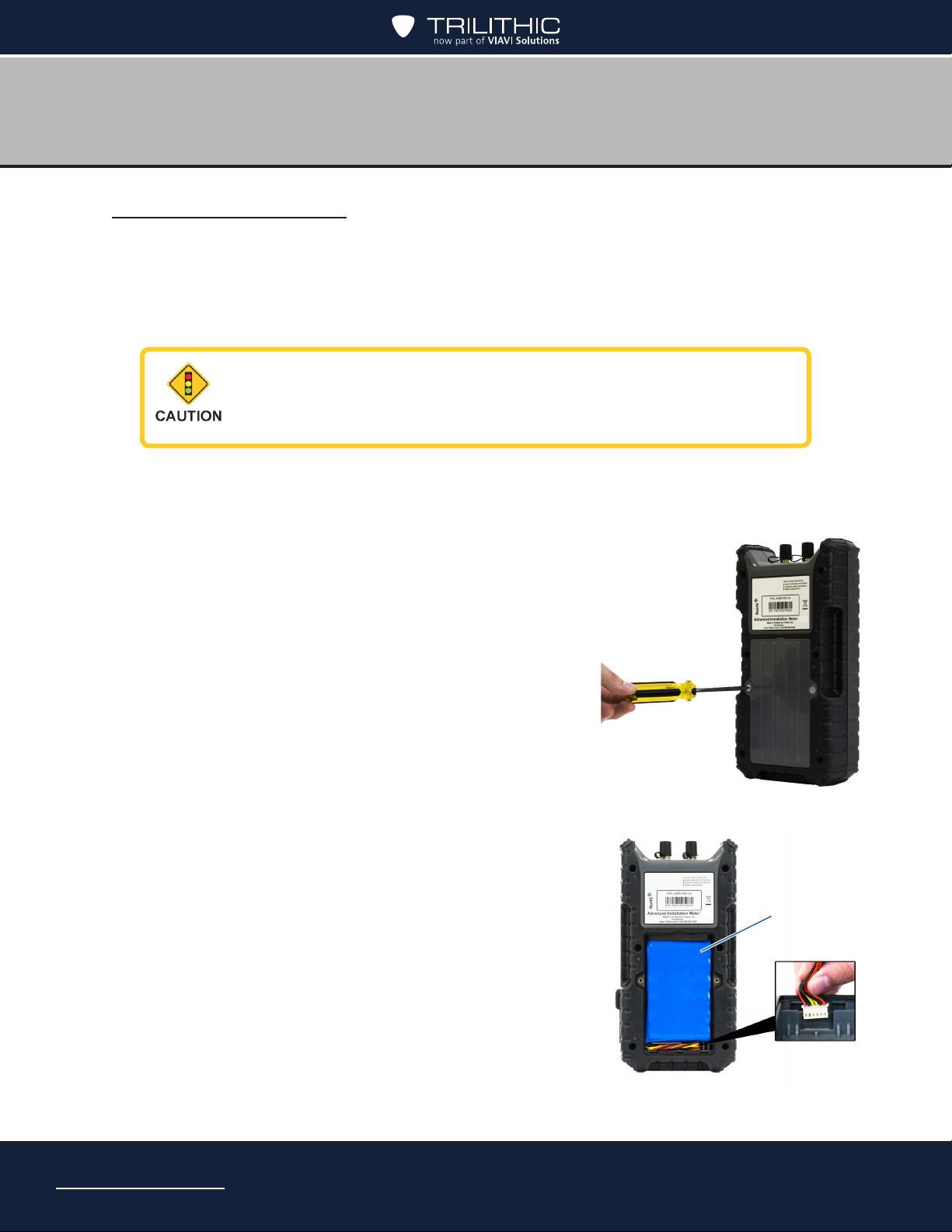
Battery Replacement
If necessary, you can replace the AIM’s battery. To obtain a new battery, contact Trilithic.
See the Spare Parts List earlier in the manual.
You also can return your AIM to Trilithic Customer Service and request that the battery be
replaced. See the Return Policy section.
Make sure the AIM is turned off and is not connected to a
power source before you remove and replace the battery.
1. Using a Phillips-head screwdriver, loosen and
remove the 2 screws from the battery door as
shown here.
2. Remove the battery cover by lifting up on the top of
the door.
3. Remove the battery pack.
4. Remove the battery connector by pulling straight up.
AIM 2 Operation Manual
Page 22
Battery pack
Battery
connector
Page 23
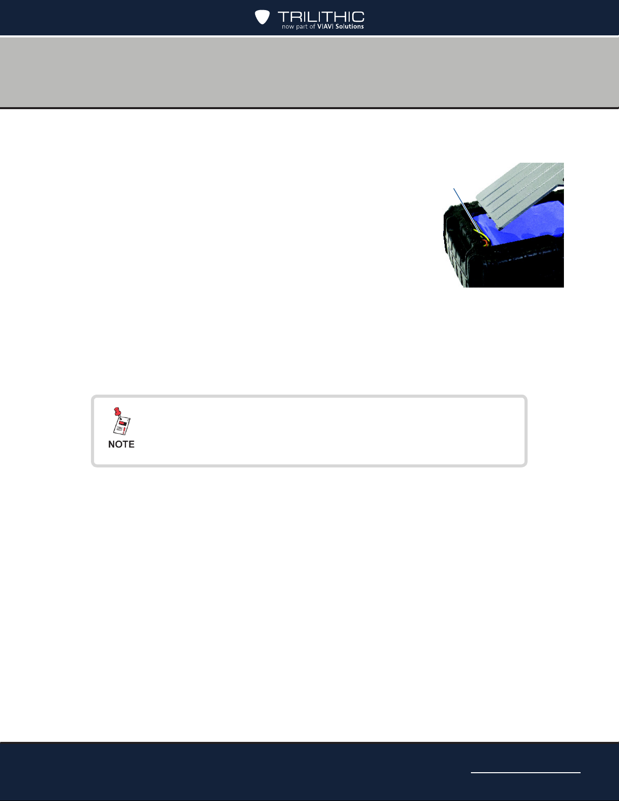
5. Connect the battery connector into the slot at the bottom right of the cavity (the slot
is keyed to only accept proper insertion).
6. Insert the battery so that the cable is in the bottom left
corner, as shown here. Place the upper right corner
Wire cable
of the battery into the cavity rst, so that the foam is
compressed to allow the pack to t snugly.
7. Push the wire cable down into the pathway. Then insert
the bottom of the battery door into the slots at the
bottom of the cavity.
8. Tilt the battery door back into place and tighten the 2
screws with a Phillipshead screwdriver.
9. To conrm that the battery has been installed correctly, press and hold the Power
button to make sure that the AIM turns on.
10. Follow local guidelines for battery disposal.
After replacing a battery, the displayed battery level may
not represent the actual battery life until the battery is fully
recharged.
AIM 2 Operation Manual
Page 23
Page 24
1
2
3
4
5
Display and Navigation
Display Screen
The AIM has a large LCD display with a backlight for easy readability. Each screen that
appears on the display has the following:
1. Title bar – Indicates the screen that is displayed
2. Battery icon – Indicates the power level of the battery
3. Main area – Shows information about the task being performed.
4. Message bar – Provides instructions to guide you through the task being performed or
5. Softkey labels – Indicate options that vary based on the screen shown. To select an
AIM 2 Operation Manual
Page 24
status messages
option, press the button below that option
Page 25

Navigation
Keep in mind the following guidelines when using the meter buttons to navigate through the
AIM’s features:
• To select a softkey option, press the button below that option.
• To highlight an option in a list, do one of the following:
– Use the arrow buttons to highlight the option.
– Use the alphanumeric keypad to enter the number for the option.
• To select a highlighted option in a list, do one of the following:
– Press the NEXT or SELECT softkey (based on the screen)
– Press the OK button
• To return to the HOME screen, do one of the following:
– Press the DONE softkey (if available)
– Press the HOME button
• To return to the previous screen, do one of the following:
– Press the BACK softkey (if available)
– Press the BACK button
AIM 2 Operation Manual
Page 25
Page 26
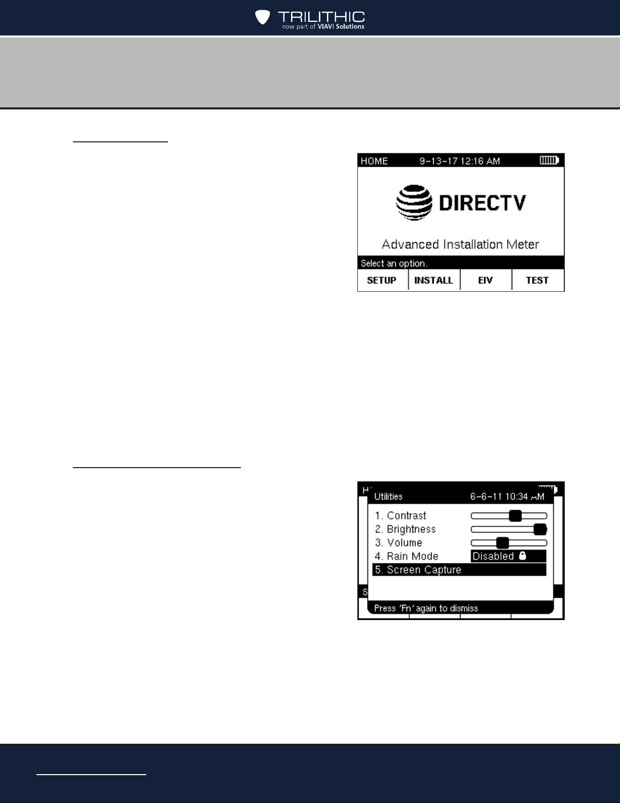
HOME Screen
The HOME screen lets you access the AIM’s main
features. You can press the HOME button at any
time to access the HOME screen.
The HOME screen provides four softkeys that
correspond to each of the main features of the
AIM:
• SETUP – Lets you set up the information for
a job. See Chapter 5: Setting Up a Job.
• INSTALL – Guides you through the steps
for aligning and performing follow-up
Extended Installation Verication (EIV) for each ODU. See Chapter 6: Installing an
ODU.
• EIV – Guides you through the steps for performing Extended Installation Verication
(EIV) at the ODU or another location to help you troubleshoot a problem. See
Chapter 7: Performing EIV.
• TEST – Lets you run network tests to help you troubleshoot a problem with an
installation. See Chapter 8: Performing Other Network Tests.
Capturing a Screenshot
If at any time you encounter a screen you want to
save for reference later, you can take a screenshot
and save it as a record.
You can capture a screen by either of these ways:
• Press the Function button and then 5
• Press Function, use the up/down arrow
buttons to highlight Screen Capture, then
press OK
The screenshot is automatically saved as a record
on the AIM. For instructions on viewing a screenshot, see the Viewing Records section.
AIM 2 Operation Manual
Page 26
Page 27
Chapter 4
Setting Up the Meter
Overview
Before you use your AIM, you should enter registration information, including your ID, name,
phone number, and company. You also should review the meter’s settings. You can change the
following settings:
• Wi-Fi
• Bluetooth
• Ethernet
• Volume
• Display contrast and brightness
• Time and date, including format
• Time limits for automatically turning off the display backlight, entering Standby mode,
and turning off the meter
To quickly adjust the setting for display contrast, display
brightness, or volume, you can press Function from any
screen.
On the UTILITIES window, use the up/down arrow buttons to
highlight the setting you want to change, then use right/left
arrow buttons to select the new level. Press Fuction to exit.
AIM 2 Operation Manual
Page 27
Page 28
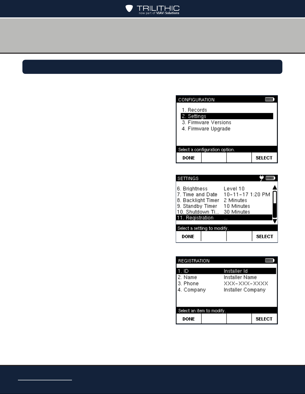
Entering Registration Information
Before you use your AIM, you should enter registration information in the meter, including your
name, ID, phone number, and company.
1. Press the CONFIG button to go to the
CONFIGURATION screen.
2. Select Settings and press SELECT to go to the
SETTINGS screen.
3. Select Registration and press SELECT to go
to the REGISTRATION screen.
4. Select the item you want to enter (ID, Name,
Phone, or Company). Then press SELECT to
go to the entry screen.
AIM 2 Operation Manual
Page 28
Page 29
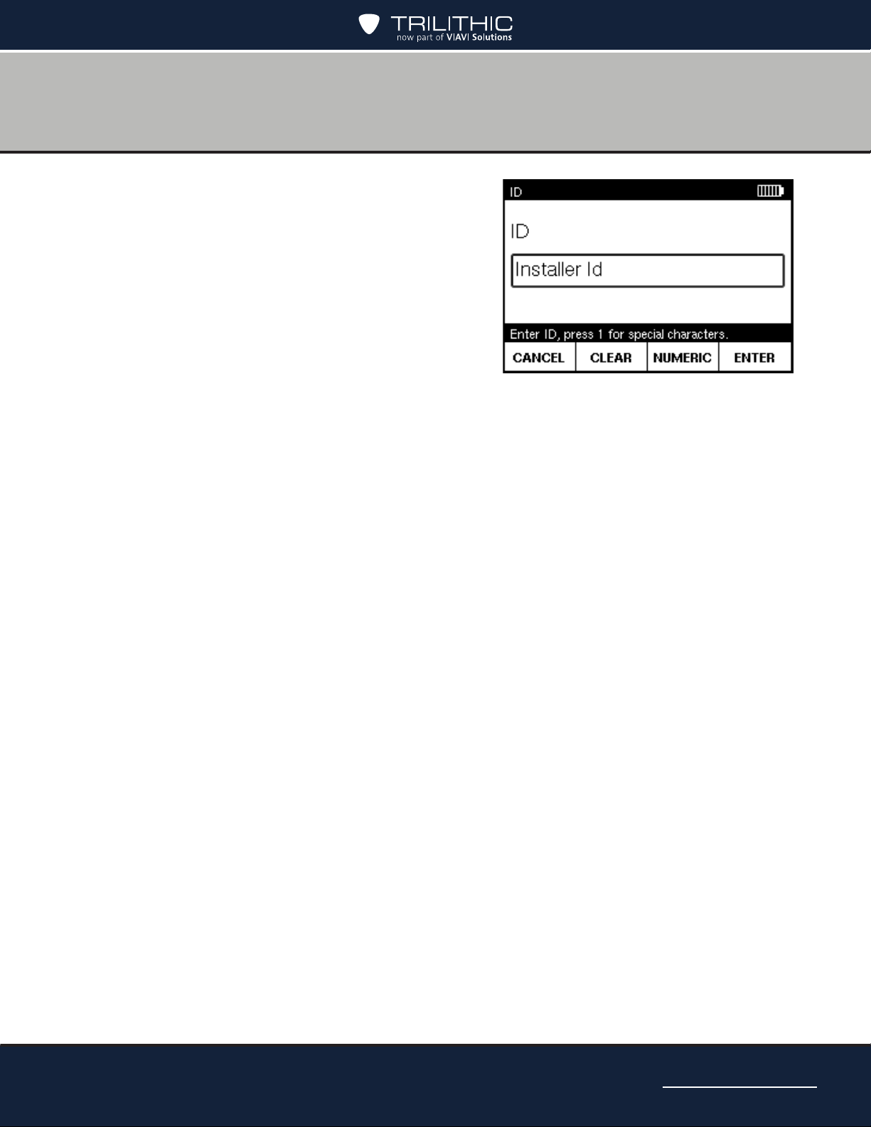
5. Use the alphanumeric keypad to enter the ID,
name, phone number or company.
• To delete a character, press the Back
button. You also can use left/right arrow
buttons to navigate within your entry, or
press CLEAR to delete the entry and start
over. Press CANCEL to exit without saving
changes.
• To enter only numbers, press NUMERIC.
To enter letters and numbers, press
ALPHA. To enter capital letters, continue pressing the letter button until the capital
letter appears.
• To enter a space or a special character (such as -, #, &, or +), press the 1 button
repeatedly until the space or character you want to enter appears.
6. Press ENTER to save and return to the REGISTRATION screen.
7. Repeat Steps 4–6 for each item on the REGISTRATION screen.
8. When nished, press DONE to return to the SETTINGS screen.
AIM 2 Operation Manual
Page 29
Page 30
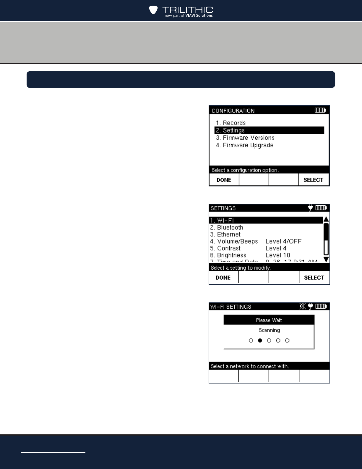
Setting up the Wi-Fi Connection
1. Press CONFIG to go to the CONFIGURATION screen.
2. Select Settings and press SELECT to go to the
SETTINGS screen.
3. Select Wi-Fi and press SELECT to go to the
WI-FI SETTINGS screen. The AIM will scan for
all available Wi-Fi networks.
AIM 2 Operation Manual
Page 30
Page 31

4. Select the network you want to connect to, then
press SELECT to go to the entry screen.
If you don’t see your network listed, select the
SCAN softkey to rescan.
5. Use the alphanumeric keypad to enter the
password.
• To delete a character, press the Back
button. You also can use left/right arrow
buttons to navigate within your entry, or
press CLEAR to delete the entry and start
over. Press CANCEL to exit without saving
changes.
• To enter only numbers, press NUMERIC. To
enter letters and numbers, press ALPHA.
To enter capital letters, continue pressing
the letter button until the capital letter
appears.
• To enter a space or a special character
(such as -, #, &, or +), press the 1 button
repeatedly until the space or character you
want to enter appears.
6. Press ENTER to save and return to the WI-FI
SETTINGS screen. “Connected” should now
appear next to the Wi-Fi network.
7. When nished, press DONE to return to the
SETTINGS screen.
You can see all Wi-Fi networks you have connected to in the
past by selecting the SAVED NETWORKS softkey. To connect
to a different network, select the network and press SELECT.
AIM 2 Operation Manual
Page 31
Page 32

Setting up the Bluetooth Connection
1. Press CONFIG to go to the CONFIGURATION screen.
2. Select Settings and press SELECT to go to the
SETTINGS screen.
3. Select Bluetooth and press SELECT to go to
the BLUETOOTH SETTINGS screen. The AIM
will enable Bluetooth and scan for all available
Bluetooth devices.
AIM 2 Operation Manual
Page 32
Page 33

4. Select the device you want to connect to, then
press SELECT. The AIM will attempt to pair
and connect with the device.
If your device is not found, make sure Bluetooth
is enabled on your device, and press the SCAN
softkey to rescan.
5. The AIM and your Bluetooth device will then
prompt you to verify the Bluetooth Passkey
number. Select OK on the AIM to conrm.
6. On your Bluetooth device, it should also display
a message to accept the Bluetooth Passkey.
Press PAIR to continue.
AIM 2 Operation Manual
Page 33
Page 34

7. On the AIM, “Connected” should now appear
next to the Bluetooth device.
You can now check for rmware updates using
your Bluetooth device’s (e.g. smartphone)
internet connection. See the Firmware Update
section later in this manual.
8. When nished, press DONE to return to the
SETTINGS screen.
You can see all Bluetooth devices you have connected to in
the past by selecting the SAVED DEVICES softkey. To connect
to a different device, select it and press SELECT.
AIM 2 Operation Manual
Page 34
Page 35

Setting up the Ethernet Connection
1. Press CONFIG to go to the CONFIGURATION screen.
2. Select Settings and press SELECT to go to the
SETTINGS screen.
3. Connect the Ethernet cable to the Ethernet port
of the AIM.
4. Select ETHERNET and press SELECT to go
to the ETHERNET SETTINGS screen. The
AIM will display the current Ethernet settings,
including the AIM’s IP address, gateway IP
address, subnet mask, and DNS addresses.
AIM 2 Operation Manual
Page 35
Page 36

IP Settings
The IP Settings menu is used to set which type of
network connection to establish when logging into
a network.
1. Select IP Settings and press SELECT to go to
the IP METHOD screen.
2. Select the IP mode for the following options and
press SELECT:
• Select DHCP to automatically obtain an IP
address and settings from a DHCP server.
These cannot be adjusted.
• Select Manual to manually enter the
network settings. In this mode, all the
network settings must be entered as shown
in the following sections.
AIM 2 Operation Manual
Page 36
Page 37

IP Address
Once IP Settings is set to Manual, you can set
each of the network IP address values.
1. Select IP Address and press SELECT to go to
the IP ADDRESS screen.
2. Enter the IP address and press SELECT.
• To delete a character, press the Back
button. You also can use left/right arrow
buttons to navigate within your entry, or
press CLEAR to delete the entry and start
over. Press CANCEL to exit without saving
changes.
3. Press ENTER to save and return to the
ETHERNET SETTINGS screen.
Gateway, Netmask, and DNS Addresses
Select each of the other IP settings as necessary and modify using the steps above.
AIM 2 Operation Manual
Page 37
Page 38

Changing the Volume Settings
1. Press CONFIG to go to the CONFIGURATION screen.
2. Select Settings and press SELECT to go to the
SETTINGS screen.
3. Select Volume and press SELECT to go to the
VOLUME screen.
4. Use the up/down arrow buttons to select the
desired volume setting.
To turn on or off the tone that sounds each time
a key is pressed, press the KEYBEEP ON /
OFF softkey.
5. When nished, press the ENTER softkey to
return to the SETTINGS screen.
AIM 2 Operation Manual
Page 38
You can temporarily turn on or turn off the meter sound by
pressing MUTE. You also can press Function to quickly adjust
the volume setting.
Page 39

Changing the Display Contrast or Brightness
1. Press CONFIG to go to the CONFIGURATION screen.
2. Select Settings and press SELECT to go to the
SETTINGS screen.
3. Select Contrast or Brightness and press
SELECT to go to the respective screen.
4. Use the left/right arrow buttons to select the
desired setting.
To turn on or off the tone that sounds each time
a key is pressed, press the KEYBEEP ON /
OFF softkey.
5. When nished, press the ENTER softkey to
return to the SETTINGS screen.
You can press Function to quickly adjust the display contrast
or display brightness settings.
AIM 2 Operation Manual
Page 39
Page 40

Changing the Time and Date Settings
1. Press CONFIG to go to the CONFIGURATION screen.
2. Select Settings and press SELECT to go to the
SETTINGS screen.
3. Select Time and Date and press SELECT to
go to the TIME and DATE screen.
4. Select the desired setting to adjust (Time
Format, Date Format, Time, or Date). Then
press SELECT to go to the entry screen.
AIM 2 Operation Manual
Page 40
Page 41

5. Select the desired format setting, or use the
numeric keypad to enter the time or date. Then
press SELECT to return to the TIME and DATE
screen.
• To delete a character, press the Back
button. You also can use the left/right
arrow buttons to navigate within your
entry, or press CLEAR to delete the
entry and start over. Press CANCEL to
exit without saving changes.
• Press the AM or PM softkey to select the time of day.
6. When nished, press the DONE softkey to return to the SETTINGS screen.
AIM 2 Operation Manual
Page 41
Page 42

Changing the Automatic Timer Settings
1. You can change the automatic timer settings for your AIM, including:
• Backlight Timer – If no buttons have been pressed on the AIM after the
specied time limit, the backlight on the display turns off.
The backlight automatically turns back on when you press any button on the
meter.
• Standby Timer – If no buttons on the AIM have been pressed after the specied
time limit, the meter automatically enters a power-saving mode called Standby.
The AIM automatically exits Standby mode when you press and hold the POWER
button until the backlight turns on.
• Shutdown Timer – If no buttons on the AIM have been pressed after the
specied time limit, the meter automatically turns off.
The meter can be turned back on by pressing and holding the POWER button
until the backlight turns on.
The AIM’s automatic timer settings are designed to help extend the battery charge.
You can customize the automatic timer settings. However, extending the time period longer
than the default setting decreases the time that the battery charge lasts.
1. Press CONFIG to go to the CONFIGURATION
screen.
2. Select Settings and press SELECT to go to the
SETTINGS screen.
AIM 2 Operation Manual
Page 42
Page 43

3. Select the desired automatic timer setting to
adjust (Backlight Timer, Standby Timer, or
Shutdown Timer). Then press SELECT to go
to the entry screen.
4. Use the numeric keypad to enter a timer
setting.
• To delete a character, press the Back
button. You also can use the left/right
arrow buttons to navigate within your
entry, or press CLEAR to delete the
entry and start over. Press CANCEL to
exit without saving changes.
• Press HOURS, MINUTES, or SECONDS
to switch between time units. The
maximum value is 4 hours.
5. When nished, press the NEXT softkey to
return to the SETTINGS screen.
AIM 2 Operation Manual
Page 43
Page 44

THIS PAGE LEFT INTENTIONALLY BLANK
AIM 2 Operation Manual
Page 44
Page 45

Chapter 5
Setting Up a Job
Overview
Before you perform tasks for an installation using the AIM, you need to set up the information
for the job. Setup tasks include setting up:
• Account number
• Notes (optional)
• Dish type
• Reverse band / International LNB
• Switch type
• Zip code
AIM 2 Operation Manual
Page 45
Page 46

Starting a Job
To start a job, enter the account number for the installation. The AIM stores information about
the tasks you perform for the installation in records associated with the account number.
For the rst job at an installation, you also set the dish type, reverse band/international LNB,
switch type, zip code, and notes either by accepting the default settings (based on the previous
job), or by changing the default settings. See the Modifying the Setup for a Job section.
1. From the HOME screen, press SETUP to go to
the MODIFY JOB SETUP screen.
2. Select Account #. Then press the SELECT
softkey to go to the ACCOUNT NUMBER
screen.
3. Using the numeric keypad, enter the account
number for the job (up to 22 digits). Then press
ENTER.
• To delete a character, press the Back
button. You also can use the left/right
arrow buttons to navigate within your
entry, or press CLEAR to delete the
entry and start over. Press CANCEL to
exit without saving changes.
The MODIFY JOB SETUP screen reappears,
showing the account number you entered and
the default settings for:
• Notes
• DishType
• Reverse Band / International LNB
• Switch Type
• Zip Code
4. When nished, press DONE to return to the HOME screen. To install an ODU without
returning to the HOME screen, press INSTALL.
AIM 2 Operation Manual
Page 46
The default settings are based on the values entered for the
previous job.
Page 47

Modifying the Setup for a Job
You can change the dish type, reverse band/international LNB, switch type, and zip code
settings for a new job or the current job from the MODIFY JOB SETUP screen. You also can
add notes for the job to include key information about the job, such as the specic room of the
installation.
To access the MODIFY JOB SETUP screen, press SETUP from the HOME screen.
Notes
1. On the MODIFY JOB SETUP screen, select
Notes and press SELECT to go to the NOTES
screen.
2. Using the keypad, enter the notes for the job.
• To delete a character, press the Back
button. You also can use left/right arrow
buttons to navigate within your entry, or
press CLEAR to delete the entry and start
over. Press CANCEL to exit without saving
changes.
• To enter only numbers, press NUMERIC. To enter letters and numbers, press
ALPHA. To enter capital letters, continue pressing the letter button until the capital
letter appears.
• To enter a space or a special character (such as -, #, &, or +), press the 1 button
repeatedly until the space or character you want to enter appears.
3. When nished, press ENTER to return to the MODIFY JOB SETUP screen.
AIM 2 Operation Manual
Page 47
Page 48

Dish Type
1. On the MODIFY JOB SETUP screen, select Dish Type and press SELECT to go to the
DISH TYPE screen.
• You also can press the number for an option
to highlight it.
• To scroll quickly through the dish types,
press PAGE UP or PAGE DN softkeys.
To exit without saving changes, press
CANCEL.
2. When nished, press SELECT to return to the
MODIFY JOB SETUP screen.
Reverse / International LNB
1. On the MODIFY JOB SETUP screen, select RB/INTL (Reverse Band / International)
and press SELECT to go to the RB/INTERNATIONAL screen.
2. Select the type of LNB for the job and press
SELECT.
• You also can press the number for an option
to highlight it.
• To exit without saving changes, press
CANCEL.
3. Select the type of switch for the job and press
SELECT.
4. If the SWiM LNB is a module, you may also
have to select the channel conguration.
5. When nished, press SELECT to return to the
MODIFY JOB SETUP screen.
AIM 2 Operation Manual
Page 48
Page 49

Switch Type
1. On the MODIFY JOB SETUP screen, select Switch Type and press SELECT to go to
the SWITCH TYPE screen.
2. Select the type of switch for the job and press
SELECT.
• You also can press the number for an option
to highlight it.
• To exit without saving changes, press
CANCEL.
3. If the SWiM LNB is a module, you may also
have to select the channel conguration.
4. When nished, press SELECT to return to the
MODIFY JOB SETUP screen.
Zip Code
1. On the MODIFY JOB SETUP screen, select Zip Code and press SELECT to go to the
ZIP CODE screen.
2. Use the numeric keypad to enter the zip code
for the job.
• To delete a character, press the Back
button. You also can use the left/right
arrow buttons to navigate within your
entry, or press CLEAR to delete the
entry and start over. Press CANCEL to
exit without saving changes.
3. When nished, press ENTER to return to the
MODIFY JOB SETUP screen.
Make sure you set up the zip code correctly. It is required to
determine the thresholds for EIV testing.
AIM 2 Operation Manual
Page 49
Page 50

THIS PAGE LEFT INTENTIONALLY BLANK
AIM 2 Operation Manual
Page 50
Page 51

Chapter 6
Installing an ODU
Overview
The AIM guides you through the steps for aligning and performing follow-up Extended
Installation Verication (EIV) for each ODU.
Aligning the ODU
The tasks for aligning an ODU vary depending on the type of ODU. All ODU types require
coarse adjustments to be made in the azimuth and elevation directions. The 95° ODU also
requires an adjustment in the tilt direction. To make coarse adjustments, move the ODU
in the appropriate direction and use the AIM to determine the position that obtains the
maximum possible signal power.
Slimline ODUs require ne adjustments (dithering) to be performed in the azimuth and
elevation directions to further hone the signal power. To dither, rotate the ne adjustment
jack screws to:
• Obtain a “reference” signal power on one side of the beam peak
• Obtain the identical strength on the other side of the beam peak
• Split the difference between the two reference points to obtain the maximum signal
power for all applicable orbital slots.
The AIM guides you through the dithering process using a series of audible tones to notify
you when the reference values have been obtained.
The DIRECTV training materials are the primary source of
ODU installation instruction. Those documents supersede the
instructions in this manual.
If you encounter an issue during the installation process and
want to save information for reference later, you can capture
an image of the AIM screen and save it as a record. See the
Chapter 3: Capturing a Screenshot section.
AIM 2 Operation Manual
Page 51
Page 52

The table below indicates which tasks need to be performed for each ODU. When an
installation includes two ODUs, you must perform the installation tasks for each ODU. The
AIM Install feature guides you through the tasks based on the selected ODU. When using
the AIM to align an ODU, refer to the appropriate sections for assistance:
• Task A. Installation Setup
• Task B. Coarse Azimuth Adjustment
• Task C. Coarse Elevation Adjustment
• Task D. Tilt Adjustment (95°, 3-LNB, Slimline-5, and Slimline-5S (SWiM) ODUs
• Only)
• Task E. Fine Elevation Adjustment (Slimline ODUs Only)
• Task F. Fine Azimuth Adjustment (Slimline ODUs Only)
ODU Installation Tasks
AIM 2 Operation Manual
Page 52
Page 53

Task A. Installation Setup
1. Set up the job for the installation. See the Starting a Job section in Chapter 5.
2. From the HOME screen, press INSTALL.
The PRE-CONFIGURE ODU screen appears
showing the default azimuth and elevation
coordinates for the job. If appropriate, the
default tilt coordinate also appears.
3. Perform the ODU site survey. Using the AIM
azimuth and elevation coordinates, conrm that
the selected location has a clear line-of-sight
to the supported orbital slots (see the ODU
Installation Tasks table on the previous page).
4. Install the ODU according to the DIRECTV
procedure.
5. Connect the AIM’s ODU F Connector to the
ODU’s LNB output.
6. Press NEXT on the PRE CONFIGURE ODU
screen.
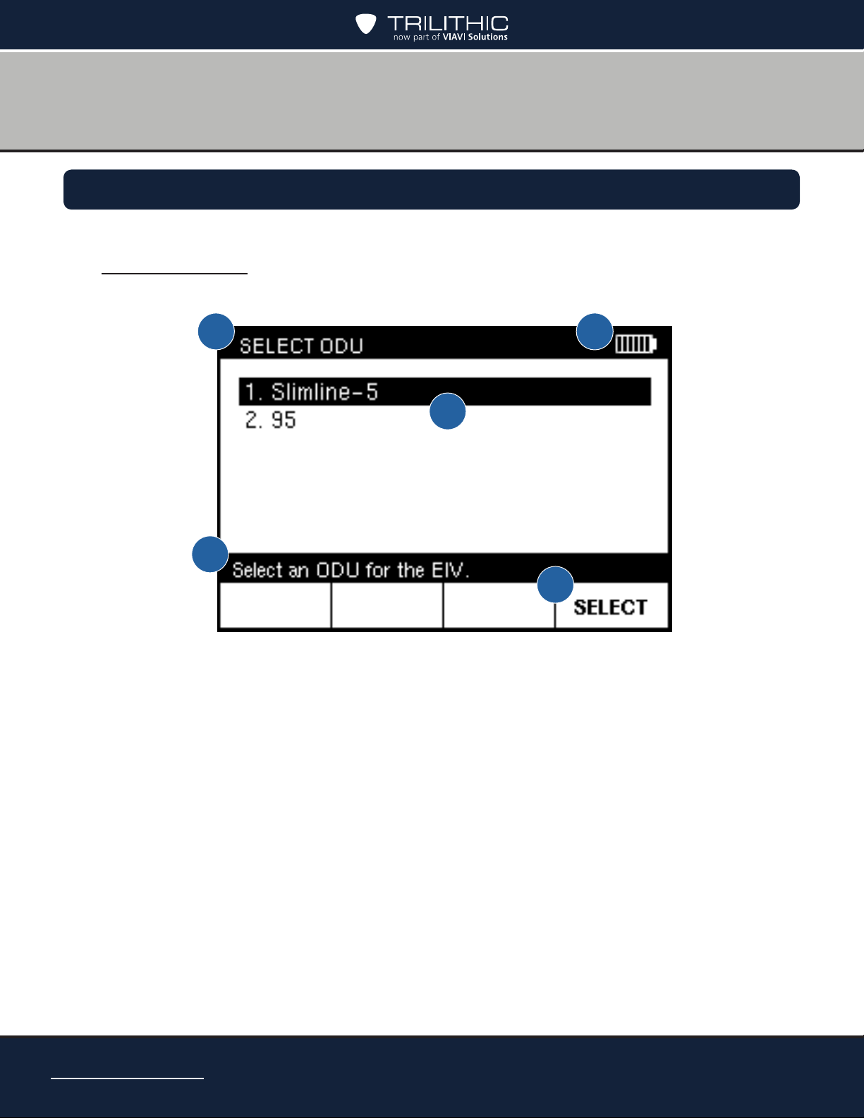
• If the installation includes two ODUs, the
SELECT ODU screen appears. Highlight
the ODU to align and press SELECT to
continue.
The default coordinates for the job are based on the ODU type
and zip code selected for the job.
AIM 2 Operation Manual
Page 53
Page 54

Task B. Coarse Azimuth Adjustment
1. While monitoring the signal power bar on the COARSE AZ & EL ADJ screen, rotate the
ODU on the mast in the azimuth direction until the maximum signal power is reached.
2. Lock down the mounting bracket collar on the
mast.
• “Locked” appears on the screen when
the signal power is above the minimum
level required to supply the IRD.
• The PEAK measurement is the
maximum signal power achieved thus far
during the installation process. To clear
the peak, press CLEAR PEAK.
Task C. Coarse Elevation Adjustment
1. Loosen the ODU’s elevation lock-down screws.
2. While monitoring the signal power bar on the COARSE AZ & EL ADJ screen, rotate the
ODU in the elevation direction until the AIM indicates that it is “locked” onto the signal
and the maximum signal power is reached.
You might need to alternate between performing the coarse
elevation adjustment and the coarse azimuth adjustment to
achieve the maximum signal power.
3. Tighten the elevation lock-down screws.
4. Press NEXT to continue.
AIM 2 Operation Manual
Page 54
Page 55

Task D. Tilt Adjustment (95°, 3-LNB, Slimline-5, and Slimline-5S (SWiM) ODUs Only)
1. Loosen the ODU’s tilt lock-down screws.
2. While monitoring the SNR bar on the TILT ADJ
screen, slowly rotate the ODU around the tilt
axis until the maximum SNR value is reached.
SNR (“signal-to-noise” ratio) is a measure of
the received signal strength relative to the
strength of the received noise, which is an
indication of the quality of the signal.
3. Tighten the tilt lock-down screws.
4. Press NEXT to continue.
For 3-LNB ODUs only, the VERIFY AZ & EL
screen appears following the tilt adjustment
to ensure the azimuth and elevation are still
properly aligned. Adjust the coarse azimuth and
elevation if necessary following the steps in the
Task B. Coarse Azimuth Adjustment and Task
C. Coarse Elevation Adjustment sections.
Task E. Fine Elevation Adjustment (Slimline ODUs Only)
1. Loosen the ODU’s elevation lock-down screws.
2. Turn the ODU’s elevation jack screw counterclockwise 2 turns.
3. On the FINE EL ADJ screen, press SET REF to set the reference value.
The AIM sounds a conrmation tone and displays the reference value.
4. Zero out the readout dial on the elevation jack screw.
5. Turn the elevation jack screw clockwise until the meter begins to sound a series of
beeps, indicating that the reference value is within 1 dB. Continue turning until the meter
sounds a conrmation tone and the displayed signal power matches the reference value
(about 4 turns).
AIM 2 Operation Manual
Page 55
Page 56

6. Refer to the ODU’s dial and use the AIM’s
numeric keypad to enter the number of turns it
took to return to the reference value (e.g. 4.50
for four and a half turns). Then press OK.
7. Zero out the readout dial on the elevation jack
screw.
8. Refer to the AIM screen and turn the elevation
jack screw counterclockwise the number of
turns indicated on the AIM screen.
9. Tighten the elevation lock-down screws.
10. Press OK and then NEXT to continue.
AIM 2 Operation Manual
Page 56
Page 57

Task F. Fine Azimuth Adjustment (Slimline ODUs Only)
1. Loosen the ODU’s azimuth lock-down screws.
2. Turn the ODU’s azimuth jack screw
counterclockwise 2 turns.
3. On the FINE AZ ADJ screen, press SET
REF to set the reference value. The AIM
sounds a conrmation tone and displays the
reference value.
4. Zero out the readout dial on the azimuth
jack screw.
5. Turn the azimuth jack screw clockwise
until the meter begins to sound a series of
beeps, indicating that the reference value
is within 1 dB. Continue turning until the
meter sounds a conrmation tone and
the displayed signal power matches the
reference value (about 4 turns).
6. Refer to the ODU’s dial and use the AIM’s
numeric keypad to enter the number of turns
it took to return to the reference value (e.g.
4.50 for four and a half turns). Then press
OK.
7. Zero out the readout dial on the azimuth
jack screw.
8. Refer to the AIM screen and turn the
azimuth jack screw counterclockwise the
number of turns indicated on the AIM
screen.
9. Tighten the azimuth lock-down screws.
10. Press OK and then NEXT to continue
AIM 2 Operation Manual
Page 57
Page 58

Performing EIV Following ODU Installation
When you complete the alignment process for the ODU, the EIV AT ODU screen appears.
You can:
• Immediately perform Extended Installation
Verication (EIV) on the ODU that you just
aligned. Follow the steps below.
• If the installation includes two ODUs, you
can press NEXT to return to the SELECT
ODU screen and align the other ODU.
• Press DONE to return to the HOME screen
and perform EIV later. For instructions, see
the Performing EIV section.
To perform the Extended Installation Verication
(EIV) for the ODU that you just aligned:
1. On the EIV AT ODU screen, press RUN EIV
and wait briey for the results.
2. On the EIV AT ODU RESULTS screen,
review the results for all supported orbital
slots and SWiM channels (if applicable).
A satisfactory result is indicated by a
checkmark. A problem is indicated by an X.
If a checkmark appears for all supported
orbital slots, the ODU alignment is
acceptable.
If X appears for an orbital slot, perform the
following steps:
• Press REPEAT EIV to conrm the
• If X appears again for one or more
• To repeat the alignment process, press REPEAT ALIGN.
AIM 2 Operation Manual
Page 58
problem.
orbital slots, you can press EIV
DETAIL to determine which tests
failed. Troubleshoot any failures
following the instructions provided by DIRECTV.
Page 59

3. When you have nished reviewing EIV results on the EIV AT ODU RESULTS
screen, you can press DONE to return to the HOME screen.
If the installation includes two ODUs, you can press NEXT to return to the SELECT
ODU screen and align the other ODU.
On the EIV AT ODU DETAILS screen, you can press NEXT
to view the details for another orbital slot, or press BACK to
scroll back through the details to the EIV AT ODU RESULTS
screen.
You also can press NOTES to add a note about the EIV.
AIM 2 Operation Manual
Page 59
Page 60

THIS PAGE LEFT INTENTIONALLY BLANK
AIM 2 Operation Manual
Page 60
Page 61

Chapter 7
Performing EIV
Overview
Extended Installation Verication (EIV) can be performed at any point in the installation to
quickly conrm that the installation is satisfactory for all supported orbital slots. EIV is an easy
way to pinpoint any potential problems with the installation. The AIM guides you through the
steps for the testing.
1. Set up the job for the installation. See the Starting a Job section in Chapter 5.
2. From the HOME screen, press EIV to go to the
EIV CONFIGURATION screen.
3. Highlight the equipment conguration for the
installation and press SELECT to go to the EIV
LOCATION screen.
If the installation includes a DSWiM-13, the EIV
CONFIGURATION screen shows two location paths, one from
the ODU to the T/TAP, and one from the T/TAP to the IRD.
AIM 2 Operation Manual
Page 61
Page 62

4. Use the left/right arrow buttons to position the
image of the AIM under the location where you
are testing.
5. Connect the AIM ODU F connector at the
location in the distribution network where you
want to test. Then press NEXT to go to the EIV
screen.
To test between the ODU and the multiswitch,
disconnect the cable connecting the ODU to
the multiswitch and connect it to the AIM’s ODU
F connector.
If the installation includes two ODUs, the
SELECT ODU screen appears. Highlight the
ODU for which you want to perform EIV and
press SELECT to go to the EIV screen.
AIM 2 Operation Manual
Page 62
Page 63

6. On the EIV screen, you can do one of the
following:
• To select an individual polarity for the
EIV, press OPTIONS. On the EIV
OPTIONS screen, highlight the polarity
for the EIV. Then press SELECT to
continue.
• To select the channel for an installation
with a DSWiM-13, where the test
location is between the DSWiM and IRD,
press OPTIONS. On the EIV OPTIONS
screen, press SELECT. Then highlight
the DSWiM channel and press SELECT.
• To add a note about the EIV, such as
details about where the EIV is being
performed, press NOTES. Then enter
the note.
• To run the test, press RUN EIV and wait
briey for the results.
AIM 2 Operation Manual
Page 63
Page 64

7. On the EIV RESULTS screen, review the
results for all supported orbital slots and SWiM
channels (if applicable). A satisfactory result
is indicated by a checkmark. A problem is
indicated by an X. An inconclusive result is
indicated by a dash.
If a checkmark appears for all supported orbital
slots, the ODU alignment is acceptable.
If an X appears for an orbital slot, perform the
following steps:
• Press REPEAT EIV to conrm the
problem.
• If an X appears again for one or
more orbital slots, you can press EIV
DETAIL to determine which tests failed.
Troubleshoot any failures following the
instructions provided by DIRECTV.
To change the location where you are testing,
press CHANGE LOC.
AIM 2 Operation Manual
Page 64
On the EIV DETAILS screen, you can press NEXT to view the
details for another orbital slot, or press BACK to scroll back
through the details to the EIV RESULTS screen.
You also can press NOTES to add a note about the EIV.
Page 65

If an X appears for the SWiM or (DSWiM), at
least one EIV transponder has failed. However,
this is not conclusive that the SWiM itself has
failed. Troubleshoot any failures following the
instructions provided by DIRECTV.
8. When you have nished reviewing EIV results
on the EIV RESULTS screen, you can press
DONE to return to the HOME screen.
You also can press CHANGE LOC to perform
EIV for another location.
AIM 2 Operation Manual
Page 65
Page 66

THIS PAGE LEFT INTENTIONALLY BLANK
AIM 2 Operation Manual
Page 66
Page 67

Chapter 8
Performing Other Network Tests
Overview
If there is a problem with a DIRECTV installation, you can run network tests to help you
troubleshoot the problem. These tests include:
• Guided Mode
• EIV Plus
• Satellite Tune test
• Transponder Survey
• Cable Resistance test
• In-Line test
• SWiM LF Power test
• SWiM Channel Assignments test
The AIM guides you through the steps for each test.
If you encounter an issue while performing a test and want to
save information for reference later, you can capture an image
of the AIM screen and save it as a record.
AIM 2 Operation Manual
Page 67
Page 68

Using Guided Mode
Guided Mode is an optimized troubleshooting process that lets you quickly and easily
identify equipment failures in an installation. The AIM guides you through a series of tests to
pinpoint the source of the failures. After each test, the AIM identies the faulty component or
recommends the next location for testing to isolate the issue. It also saves the results of the
test for later review. Guided Mode makes troubleshooting easy by using the AIM’s built-in
intelligence to recommend the next step.
Guided Mode leads you through a series of tests (called EIV Plus) at various locations in the
distribution network. EIV Plus can also be used as an independent troubleshooting tool. For
more information on EIV Plus, see the next section.
If a Guided Mode test fails and the failure could be
due to inclement weather, you can use the Rain
Mode feature to continue troubleshooting in Guided
Mode. Rain Mode allows for a slight degradation in
the RF signal in order to account for environmental
conditions, allowing you to continue troubleshooting
beyond the ODU. If a Guided Mode test was run
using Rain Mode, the Rain Mode icon appears on
the Results screen. While Rain Mode accounts for
environmental factors, it does not increase the chance
of passing Installation Verication (IV) at the IRD.
1. Set up the job for the installation. See the Starting a Job section in Chapter 5.
2. From the HOME screen, press TEST to go to the TEST screen.
3. Highlight GUIDED MODE and press SELECT to go to the GUIDED SETUP screen.
AIM 2 Operation Manual
Page 68
Guided mode is not available for DSWiM-13 congurations or
for the Slimline-3DS ODU.
Rain Mode can only be enabled in Guided Mode after the ODU
has been repointed as part of troubleshooting; it remains
disabled at all other times while in Guided Mode. The unlock
icon on the Function menu indicates that Rain Mode can be
enabled. When the lock icon is shown, Rain Mode cannot be
enabled.
Page 69

4. Verify the setup information for the job.
Then press START to go to the GUIDED
CONFIGURATION screen.
If the setup information is incorrect, press
SETUP to go to the MODIFY JOB SETUP
screen. Follow the instructions in the Starting
a Job section in Chapter 5 to modify the setup
information. Then press RETURN TO GUIDED
to return to the GUIDED SETUP screen.
5. Highlight the equipment conguration for the
installation and press SELECT to go to the
GUIDED LOCATION screen.
AIM 2 Operation Manual
Page 69
Page 70

6. Connect the AIM ODU F connector at the
location in the distribution network indicated on
the display. Then press RUN TEST and wait for
the results.
7. On the GUIDED RESULTS screen, review the
results of the EIV Plus. Then do one of the
following:
• To view detailed results, press DETAILS
to go to the GUIDED DETAILS screen.
Go to Step 8.
• To repeat EIV Plus at the same location,
press REPEAT TEST and wait for the
results of the test.
• If results indicate a problem with the
ODU alignment, press REPOINT to go
to the PRE CONFIGURE ODU screen.
Then follow the instructions in Chapter 6
to align the ODU.
• To continue troubleshooting, press NEXT
to go to the GUIDED LOCATION screen
and perform EIV Plus at a new location. Repeat Step 6.
• When all problems have been addressed and troubleshooting is complete, you
can press DONE to return to the TEST screen.
If it is raining and an attempt to realign the ODU fails, you can
enable Rain Mode to account for environmental conditions
and continue troubleshooting.
Press Fn and then 4 to enable Rain Mode. Press Repeat
Test and wait for the results of the test. The Rain Mode icon
appears on the Results screen to indicate the test was run
in Rain Mode. If the test fails again, the failure may be due to
signal degradation from the rain, or there may an issue with
the LNB.
AIM 2 Operation Manual
Page 70
Page 71

8. On the GUIDED DETAILS screen, review the
possible problems with the installation. Then do
one of the following:
• To view results of the EIV Plus, press
EIV PLUS RESULTS to go to the
GUIDED EIV PLUS RESULTS screen.
Go to Step 9.
• To view cumulative results for all EIV
Plus tests performed in Guided Mode
for the installation, press VIEW DATA to
go to the GUIDED DATA screen. Go to
Step 10.
• To continue troubleshooting, press
DONE to go back to the GUIDED
RESULTS screen. Go back to Step 7.
9. On the GUIDED EIV PLUS RESULTS screen,
review the results for all supported orbital
slots and SWiM channels (if applicable). A
satisfactory result is indicated by a checkmark.
A problem is indicated by an X. An inconclusive
result is indicated by a dash.
• If an X appears for one or more orbital
slots, you can press EIV PLUS DETAIL
to determine which tests failed. Then
press NEXT to view the details for
another orbital slot, or press BACK to
scroll back through the details to the
GUIDED EIV PLUS RESULTS screen.
• When you have nished reviewing EIV
Plus results on the GUIDED EIV PLUS
RESULTS screen, you can press DONE to return to the GUIDED DETAILS
screen.
AIM 2 Operation Manual
Page 71
Page 72

10. On the GUIDED DATA screen, review the
results for each EIV Plus performed in Guided
Mode for the installation. Results for each
EIV Plus are listed in sequential columns; a
satisfactory result is indicated by a checkmark
and a problem is indicated by an X.
• Press PAGE UP or PAGE DOWN to
navigate through the results.
• When you have nished reviewing
results on the GUIDED DATA screen,
you can press DONE to return to the GUIDED DETAILS screen.
AIM 2 Operation Manual
Page 72
Page 73

Performing EIV Plus
You can use EIV Plus to perform a series of tests to help you quickly identify potential
problems with an installation. EIV Plus performs the same tests as in Guided Mode, but
requires you to interpret the results and determine the next steps for troubleshooting (instead
of providing a recommendation).
EIV Plus and Guided Mode include one or more of the following tests, depending on the
conguration:
• B-Band Transponder test – For Slimline-3 and Slimline-5 ODUs, veries proper
operation at low-frequencies (250 to 750 MHz).
• A-Band Transponder test – For Slimline-3 and Slimline-5 ODUs, veries proper
operation at high frequencies (1650 to 2150 MHz).
• LNB Verication test – For all Slimline ODUs, veries that the installed equipment
matches the conguration entered in the AIM.
• 22 kHz Tone Control test – For all ODUs except SWiM ODUs and Round (18”),
veries the tone control of the multiswitch and the LNB.
• 18-Volt test – For all ODUs except SWiM ODUs, veries the voltage control of the
multiswitch and the LNB.
• BBC Switched Mode test – For congurations with BBCs, veries the Ku band passes
through the BBC in switched mode.
• SL3 101 Transponders on Tone Ports test – For Slimline-3 ODUs, veries the 101
transponders using 13-Volt and 18-Volt tones.
• SWiM Channel Assignments test – For SWiM ODUs and SWiM multiswitches, veries
the Receiver IDs (RIDs) and SWiM channel assignments for each IRD.
AIM 2 Operation Manual
Page 73
Page 74

If an EIV Plus test fails and the failure could be due to
inclement weather, you can use the Rain Mode feature
to continue troubleshooting with EIV Plus. Rain Mode
allows for a slight degradation in the RF signal in order
to account for environmental conditions, allowing
you to continue troubleshooting beyond the ODU. If
an EIV Plus test was run using Rain Mode, the Rain
Mode icon appears on the Results screen. While Rain
Mode accounts for environmental factors, it does not
increase the chance of passing Installation Verication
(IV) at the IRD.
For easy troubleshooting, you can use Guided Mode
to let the AIM’s built-in intelligence guide you through a
series of EIV Plus tests at recommended locations to
identify an issue. Or, you can perform EIV Plus at any
location in the distribution network for an installation,
following the steps below.
1. Start the job for the installation.
2. From the HOME screen, press TEST to go to
the TEST screen.
3. Highlight EIV Plus and press SELECT to go to the EIV PLUS CONFIGURATION
screen.
4. Highlight the equipment conguration for the installation and press SELECT to go to the
EIV PLUS LOCATION screen.
AIM 2 Operation Manual
Page 74
Page 75

5. Use the left/right arrow buttons to position the
image of the AIM under the location where you
are testing.
6. Connect the AIM ODU F connector at the
location in the distribution network where you
want to test. Then press NEXT to go to the EIV
PLUS TEST screen.
To test between the ODU and the multiswitch,
disconnect the cable connecting the ODU to
the multiswitch and connect it to the AIM’s ODU
F connector.
If the installation includes two ODUs, the EIV
PLUS screen appears. Highlight the ODU for
which you want to perform EIV Plus and press
SELECT to go to the EIV PLUS TEST screen.
AIM 2 Operation Manual
Page 75
Page 76

7. On the EIV PLUS TEST screen, you can do
one of the following:
• To select an individual polarity for the
EIV Plus, press OPTIONS. On the EIV
PLUS OPTIONS screen, highlight the
polarity for the EIV Plus.Then press
SELECT to continue.
• To select the channel for an installation
with a DSWiM-13 where the test location
is between the DSWiM and IRD, press
OPTIONS. On the EIV PLUS OPTIONS
screen, press SELECT. Then highlight
the DSWiM channel and press SELECT.
• To add a note about the EIV Plus, such
as details about where the EIV Plus is
being performed, press NOTES. Then
enter the note.
• To run the test, press RUN EIV PLUS
and wait briey for the results.
8. On the EIV PLUS RESULTS screen, review the
results for all supported orbital slots and SWiM channels (if applicable). A satisfactory
result is indicated by a checkmark. A problem is indicated by an X. An inconclusive
result is indicated by a dash.
• If a checkmark appears for all supported orbital slots, the ODU alignment is
acceptable.
• If an X appears for an orbital slot, perform the following steps:
• Press REPEAT EIV PLUS to conrm the problem.
• If X appears again for one or more orbital slots, you can press EIV
PLUS DETAIL to determine which tests failed. Troubleshoot any failures
following the instructions provided by DIRECTV.
AIM 2 Operation Manual
Page 76
Page 77

If it is raining and an attempt to realign the ODU fails, you can
enable Rain Mode to account for environmental conditions
and continue troubleshooting.
Press Fn and then 4 to enable Rain Mode. Press Repeat
Test and wait for the results of the test. The Rain Mode icon
appears on the Results screen to indicate the test was run
in Rain Mode. If the test fails again, the failure may be due to
signal degradation from the rain, or there may an issue with
the LNB.
9. When you have nished reviewing EIV Plus
results on the EIV PLUS RESULTS screen, you
can press DONE to return to the HOME screen.
You also can press CHANGE LOC to perform
EIV Plus for another location.
On the EIV PLUS DETAILS screen, you can press NEXT to
view the details for another orbital slot, or press BACK to
scroll back through the details to the EIV PLUS RESULTS
screen.
You also can press NOTES to add a note about the EIV Plus.
AIM 2 Operation Manual
Page 77
Page 78

Performing a Satellite Tune Test
You can use the AIM’s Satellite Tune feature to tune to any DIRECTV transponder. Connecting
the AIM in different locations in the distribution network, you can progressively test each
segment of the connection between the ODU and the IRD to locate a problem.
1. Set up the job for the installation. See the
Starting a Job section in Chapter 5.
2. From the HOME screen, press TEST to go to
the TEST screen.
3. Highlight Satellite Tune and press SELECT
to go to the SAT TUNE CONFIGURATION
screen.
4. Highlight the equipment conguration for the
installation and press SELECT to go to the SAT
TUNE LOCATION screen.
5. Use the left/right arrow buttons to position the
image of the AIM under the location where you
are testing.
AIM 2 Operation Manual
Page 78
Page 79

6. Connect the AIM ODU F connector at the
location in the distribution network where you
want to test.
To test between the ODU and the multiswitch,
disconnect the cable connecting the ODU to
the multiswitch and connect it to the AIM’s ODU
F connector.
7. Press NEXT to go to the SAT TUNE screen.
8. If the installation includes two ODUs, highlight
the ODU to test and press SELECT to
continue.
9. Highlight the orbital slot to test or use the
keypad to enter the slot number, and press
SELECT to continue.
10. If you want to set the SWiM (or DSWiM)
channel for the test, do the following:
• Press OPTIONS.
• On the SAT TUNE OPTIONS screen,
press SELECT to select Set SWiM Ch.
(Connect SWiM).
• Highlight the desired channel and press
SELECT.
11. Highlight the transponder to test. Then press
SELECT and wait briey for the results of the
test.
You also can use the keypad to enter the
transponder number. Use PAGE UP or PAGE
DN to scroll quickly through the transponders.
AIM 2 Operation Manual
Page 79
Page 80

12. On the SAT TUNE RESULTS screen, review
the results of the test. The screen shows:
• Power of the transponder signal (in
dBm—power ratio in decibels of the
measured power referenced to one
milliwatt).
• Measurement of the signal-to-noise ratio,
expressed as SNR in decibels.
• Measurement of the signal quality,
expressed as an SQ value between 0
and 100.
• Frequency offset of the transponder signal from its expected frequency (in
megahertz).
• Indication as to whether the transponder signal is above the power lock
threshold.
13. Troubleshoot any problems following the instructions provided by DIRECTV.
• To repeat the test at a different location, press CHANGE LOC. Then go to Step
5.
• To repeat the test at a different orbital slot, press CHANGE SAT. Then go to Step
9.
• To repeat the test at a different transponder, press CHANGE TR. Then go to Step
10.
To repeat the test for a sequential transponder, use the up/down arrow buttons
to change the transponder number to the next or previous transponder. The SAT
TUNE RESULTS screen updates to show the results of the test for the selected
transponder.
14. Press DONE to return to the TEST screen.
AIM 2 Operation Manual
Page 80
Page 81

Performing a Transponder Survey
You can use the AIM’s Transponder Survey feature to record the signal power, signal-to-noise
ratio (SNR), frequency offset, and lock status for all transponders that can be received using
the selected equipment. This can help to determine the location of a problem for an installation.
Connecting the AIM in the distribution network, you
can progressively test each segment of the connection
between the ODU and the IRD to locate a problem.
1. Set up the job for the installation. See the
Starting a Job section in Chapter 5.
2. From the HOME screen, press TEST to go to
the TEST screen.
3. Highlight Transponder Survey and
press SELECT to go to the SURVEY
CONFIGURATION screen.
4. Highlight the equipment conguration for the
installation and press SELECT to go to the
SURVEY LOCATION screen.
5. Use the left/right arrow buttons to position the
image of the AIM under the location where you
are testing.
AIM 2 Operation Manual
Page 81
Page 82

6. Connect the AIM ODU F connector at the
location in the distribution network where you
want to test.
7. Press NEXT to go to the TRANSPONDER
SURVEY screen.
8. If the installation includes two ODUs, highlight
the ODU to test and press SELECT to
continue.
9. If you want to select an individual polarity for
the transponder survey, do the following:
• Press OPTIONS.
• On the TR SURVEY OPTIONS screen,
highlight the polarity for the survey.
• To continue, press SELECT to go to the
TRANSPONDER SURVEY screen.
AIM 2 Operation Manual
Page 82
Page 83

10. If you want to set the SWiM (or DSWiM)
channel for the transponder survey, do the
following:
• Press OPTIONS.
• On the TR SURVEY OPTIONS screen,
highlight Set SWiM Ch. (Connect
SWiM).
• Highlight the desired channel and press
SELECT to go to the TRANSPONDER
SURVEY screen.
11. Press RUN TR SURVEY to start the test. The screen indicates each orbital slot and
transponder as they are scanned.
12. When the scan test is complete, press VIEW to go to the TR SURVEY RESULTS
screen.
To add a note about the transponder survey, such as details
about where the survey is being performed, press NOTES.
To test spot transponders in the survey, press WITH SPOTS.
To remove spot transponders from the survey, press
WITHOUT SPOTS.
AIM 2 Operation Manual
Page 83
Page 84

13. Use the up/down arrow buttons to review
the results of the test. The screen shows the
following information for each transponder:
• Frequency of the transponder signal
• Power of the transponder signal (in
dBm—power ratio in decibels of the
measured power referenced to one
milliwatt)
• Measurement of the signal-to-noise ratio,
expressed as SNR in decibels
• Measurement of the signal quality, expressed as an SQ value between 0 and 100
• Frequency offset of the transponder signal from its expected frequency (in
megahertz)
• Indication whether the transponder signal is above the power lock threshold
• Voltage supplied (in volts)
• Current supplied (in milliamps)
• ODU used
• SWiM channel used
14. Troubleshoot any problems following the instructions provided by DIRECTV. To repeat
the test at a different location, press CHANGE LOC
15. Press DONE to return to the TEST screen.
Use PAGE UP and PAGE DN to scroll quickly through test
results. Press the left/right arrow buttons to navigate through
the columns.
AIM 2 Operation Manual
Page 84
Page 85

Performing a Cable Resistance Test
You can use the AIM’s Cable Resistance test feature to help determine whether there is a
problem with a cable used in the distribution network. To complete this test, you must use the
25 Ω Cable Test Load (provided with the AIM). By placing the Cable Test Load on the end of a
cable, you can determine the resistance value for the
cable. A high resistance value indicates that the cable
may have been inadvertently cut. A low resistance
value indicates that the cable may have a short.
1. Set up the job for the installation. See the
Starting a Job section in Chapter 5.
2. From the HOME screen, press TEST to go to
the TEST screen.
3. Highlight Cable Resistance Test and press
SELECT to go to the CABLE RESISTANCE
TEST screen.
4. Connect the 25 Ω Cable Test Load to the AIM
ODU F connector.
5. Press NEXT to conrm the resistance of the
Cable Test Load.
If the resistance is outside of the allowable
range, a message appears. Perform the
following steps:
• Press RE-TEST to conrm the problem.
• If the resistance is still outside of the range,
the Cable Test Load has failed. Replace
the Cable Test Load and re-start the Cable
Resistance test.
25 Ω Cable Test Load
AIM 2 Operation Manual
Page 85
Page 86

6. Connect the Cable Test Load to one end of the
cable you want to test. Then connect the other
end of the cable to the AIM ODU F connector.
7. Press NEXT and wait briey for the results of
the test.
8. On the CABLE RESISTANCE RESULTS
screen, review the resistance of the cable in
ohms, adjusted for the 25 Ω Cable Test Load.
9. Troubleshoot any problems following the
instructions provided by DIRECTV.
To repeat the Cable Resistance test, press
REPEAT.
10. Press DONE to return to the TEST screen.
AIM 2 Operation Manual
Page 86
If a message appears stating that DC voltage was detected,
the cable is not connected to the Cable Test Load.
Make sure you are testing the appropriate cable, then press
NEXT to continue the test.
Page 87

Performing an In-Line Test
You can use the AIM’s In-Line test feature to help determine the cause of a problem in an
installation. Connecting the AIM in series with the equipment, you can progressively test each
segment of the connection between the ODU and the IRD to locate a problem. The AIM can
measure the voltage, current, and 22 kHz signals to verify that the correct control signals are
being transmitted through the coaxial cable.
1. Set up the job for the installation. See the
Starting a Job section in Chapter 5.
2. From the HOME screen, press TEST to go to
the TEST screen.
3. Highlight In-Line Test and press SELECT to go
to the IN-LINE CONFIGURATION screen.
4. Highlight the equipment conguration for the
installation and press SELECT to go to the INLINE LOCATION screen.
AIM 2 Operation Manual
Page 87
Page 88

5. Use the left/right arrow buttons to position the
image of the AIM under the location where you
are testing.
6. Connect the AIM in series with the equipment
at the location where you want to test.
To test between the ODU and the multiswitch,
disconnect the cable connecting the ODU to
the multiswitch and connect it to the AIM’s ODU
F connector. Then connect the AIM’s IRD F
connector to the multiswitch.
7. Press NEXT and wait briey for the results of
the test.
8. On the IN-LINE TEST RESULTS screen,
review the results of the test. The screen
indicates whether the test passed or failed. The
screen also shows:
• Voltage supplied (in volts).
• Current supplied (in milliamps).
• If present, amplitude of the 22 kHz tone.
• Indication as to whether DiSEqC commands are being received by the
multiswitch (MSW) and BBC.
9. Troubleshoot any problems following the instructions provided by DIRECTV.
10. Press DONE to return to the TEST screen.
As messages are received from the multiswitch (MSW) and
BBC, the multiswitch port and BBC frequency range ash
bold. If no messages are received, “N/A” appears.
AIM 2 Operation Manual
Page 88
Page 89

Performing a SWiM LF Power Test
You can use the AIM’s SWiM LF Power test feature to determine whether there is a
communications problem between the SWiM and the IRD. To perform this test, disconnect all
IRDs in the distribution network, then connect the AIM in place of an IRD. The AIM determines
whether the SWiM LF Power level is sufcient.
1. Set up the job for the installation. See the
Starting a Job section in Chapter 5.
2. From the HOME screen, press TEST to go to
the TEST screen.
3. Highlight SWiM LF Power Test and press
SELECT to go to the SWiM LF POWER TEST
screen.
4. Disconnect all IRDs in the distribution network.
Then connect the AIM in place of an IRD.
5. Press NEXT and wait briey for the results of
the test.
6. On the SWiM LF POWER TEST RESULTS
screen, review the results of the test.
The screen shows whether the SWiM LF power
level is sufcient.
7. Troubleshoot any problems following the
instructions provided by DIRECTV.
To repeat the SWiM LF Power test in case of a
failure, press RETRY.
8. Press DONE to return to the TEST screen.
AIM 2 Operation Manual
Page 89
Page 90

Performing a SWiM Channel Assignments Test
You can use the AIM’s SWiM Channel Assignments test feature to view the Receiver IDs
(RIDs) and assigned SWiM or DSWiM channels for each IRD in the installation. If you suspect
that the network could be oversubscribed, the results show whether all available SWiM or
DSWiM channels are used, indicating the possibility that the number of IRDs in the network
exceeds the SWiM’s capacity.
To perform this test, connect the AIM at any point in
the distribution network between the SWiM and the
IRD. Power for the SWiM must be provided by an
external power inserter, since the AIM cannot be used
to provide power during the test.
1. Set up the job for the installation. See the
Starting a Job section in Chapter 5.
2. From the HOME screen, press TEST to go to
the TEST screen.
3. Highlight SWiM Channel Assignments and
press SELECT to go to the SWiM CHANNEL
SETUP screen.
4. Connect the AIM ODU F connector at any
point in the distribution network between the
SWiM and the IRD. Make sure that power for
the SWiM is provided by an external power
inserter.
5. Press NEXT and wait briey for the results of
the test. screen.
The DSWiM requires an open channel to run the test. If all
channels are subscribed, a message appears stating that all
channels are occupied and to remove the IRD and try again.
AIM 2 Operation Manual
Page 90
Page 91

6. On the SWiM CHANNEL RESULTS screen,
review the results. For each IRD in the network,
the screen shows the RID and the SWiM
channel used. The number of available SWiM
channels is also indicated.
Troubleshoot any problems following the
instructions provided by DIRECTV.
7. Press DONE to return to the TEST screen.
AIM 2 Operation Manual
Page 91
Page 92

THIS PAGE LEFT INTENTIONALLY BLANK
AIM 2 Operation Manual
Page 92
Page 93

Chapter 9
Managing Records
Overview
The AIM stores information for each account, including the results for each EIV, EIV Plus,
Guided Mode test, and Transponder Survey. Screenshots are also stored as records. For all
accounts, you can:
• View records
• Delete records
• Transfer records to and from a USB ash drive
The AIM can hold up to 100 records for each record type. When there are 100 stored records
for a particular record type and a new record is added, the oldest record of that type is deleted.
Understanding Records
The AIM stores the following types of records:
• EIV – Test results and data for a particular EIV.
• EIV+ – Test results and data for a particular EIV Plus.
• Guided – Test results and data for a particular Guided Mode test.
• Survey – Test results and data for a particular Transponder Survey.
• Image – Thumbnail screenshot, as well as the date and time the image was taken, and
the associated account number.
AIM 2 Operation Manual
Page 93
Page 94

Viewing Records
You can view records for tests performed on the AIM, including EIV, EIV Plus, Guided Mode,
and Transponder Survey, as well as screenshots. You can select a record to view from a list of
all records on the AIM, or view records by account number.
1. Press CONFIG to go to the CONFIGURATION
screen.
2. Highlight Records and press SELECT to go to
the RECORDS MAIN screen.
3. Highlight View All Records and press SELECT
to go to the VIEW RECORDS screen.
Alternatively, if you want to view records for a
selected account number, do the following:
• Highlight View By Account Number
and press SELECT to go to the VIEW
RECORDS BY ACCOUNT screen.
• Highlight the account number you want
to view and press SELECT to go to the
VIEW RECORDS screen.
AIM 2 Operation Manual
Page 94
Page 95

4. Highlight the record you want to view and
press SELECT. The VIEW INFO screen for the
selected record appears.
5. On the VIEW INFO screen, you can do the
following (example screens are shown):
• Copy, move, or delete the record by
pressing OPTIONS. On the Options
window, highlight the action you want to
perform and press OK.
• View the next or previous record by
pressing NEXT RECORD or PREVIOUS
RECORD.
• For a test record, view the results of the
test on the VIEW DATA screens for the
selected record by pressing NEXT.
• For a screenshot, press and hold FULL
SCREEN to view the full image on the
SCREENSHOT INFO screen.
AIM 2 Operation Manual
Page 95
Page 96

6. On the VIEW DATA screens, you can do the
following (example screens are shown):
• Scroll through the results using PAGE
UP and PAGE DN.
• View the next data screen by pressing
NEXT.
• Return to the VIEW RECORDS screen
by pressing DONE.
For more details on results for a specic test,
see the Performing EIV section (for EIV) or the
Performing Other Network Tests section on
(for EIV Plus, Guided Mode, or Transponder
Survey).
If the column header for an EIV Plus or Guided
Mode test is black with white text, this indicates
that the test was run in Rain Mode.
AIM 2 Operation Manual
Page 96
Page 97

Deleting Records
You can delete records stored on the AIM, including:
• An individual record
• All records for a selected account
• All records for all accounts
• All records of a selected type (EIV, EIV
Plus, Guided Mode, Transponder Survey, or
Screenshots).
1. Press CONFIG to go to the CONFIGURATION
screen.
2. Highlight Records and press SELECT to go to
the RECORDS MAIN screen. Then highlight
one of the following:
• To delete all records on the AIM or
records of a selected type, highlight
Quick Delete All and press SELECT.
Go to Step 3.
• To delete an individual record, highlight
View All Records and press SELECT.
Go to Step 4.
• To delete all records for an account,
highlight View By Account Number and
press SELECT. Go to Step 5.
AIM 2 Operation Manual
Page 97
Page 98

3. To delete all records on the AIM or records of a
selected type, do the following on the QUICK
DELETE RECORDS screen:
• Highlight the type of records to delete
and press SELECT. You can select
Delete All Records to delete all records
on the AIM, or select a specic type of
records to delete.
• Go to Step 6.
4. To delete an individual record, do the following
on the VIEW RECORDS screen:
• Highlight the record to delete and press
OPTIONS.
• On the Options window, highlight Delete
and press OK.
• Go to Step 6.
AIM 2 Operation Manual
Page 98
Page 99

5. To delete all records for an account, do
the following on the VIEW RECORDS BY
ACCOUNT screen.
• Highlight the account number and press
OPTIONS.
• On the Options window, highlight
Delete... and press OK.
• Highlight the type of records to delete
and press OK. You can select Delete
All Records to delete all records for
the account, or select a specic type of
records to delete.
• Go to Step 6.
6. On the message that appears to conrm the
deletion, press OK.
The records are deleted. Press OK again to
acknowledge the deletion, and the RECORDS
MAIN, VIEW RECORDS, or VIEW RECORDS
BY ACCOUNT screen appears.
AIM 2 Operation Manual
Page 99
Page 100

Transferring Records
You can transfer records from your AIM to a PC using a USB ash drive. You also can transfer
records from a USB ash drive to the AIM (see page 92). You can transfer:
• An individual record
• All records for a selected account
• All records for all accounts
• All records of a selected type (EIV, EIV Plus,
Guided Mode, Transponder Surveys, or
Screenshots).
When transferring records between the AIM and a
USB ash drive, you can choose from two options:
• To retain a copy of the records on the device
you are transferring from, select Copy.
• To permanently delete the records from the
device you are transferring from, select Move.
Transferring records from the AIM to
a USB ash drive
1. Insert the USB ash drive in the appropriate
USB connector on the meter.
2. Press CONFIG to go to the
CONFIGURATION screen.
3. Highlight Records and press SELECT to go to the RECORDS MAIN screen. Then
highlight one of the following options:
• To transfer all records on the AIM or records of a selected type, highlight
Quick Copy All or Quick Move All and press SELECT. Go to Step 4.
• To transfer an individual record, highlight View All Records and press
SELECT. Go to Step 5.
• To transfer all records for an account, highlight View By Account Number
and press SELECT. Go to Step 6.
AIM 2 Operation Manual
Page 100
 Loading...