

Page 1
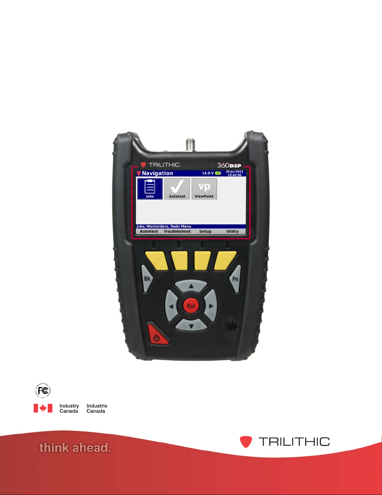
360 DSP
Next Generation Certification Meter
Wi-Fi Option
Operation Manual
This equipment has been tested and found to comply with the limits for a Class B digital device, pursuant to Part
15 of the FCC Rules. See Page 2 for complete details.
This Class B digital apparatus complies with Canadian ICES-003. See Page 2 for complete
details.
Page 2
FCC Part 15 Compliance
Note: This equipment has been tested and found to comply with the limits for a Class B
digital device, pursuant to Part 15 of the FCC Rules. These limits are designed to provide
reasonable protection against harmful interference in a residential installation. This
equipment generates, uses, and can radiate radio frequency energy and, if not installed
and used in accordance with the instructions, may cause harmful interference to radio
communications. However, there is no guarantee that interference will not occur in a particular
installation.
If this equipment does cause harmful interference to radio or television reception, which can be
determined by turning the equipment off and on, the user is encouraged to try to correct the interference
by one or more of the following measures:
Reorient or relocate the receiving antenna
Increase the separation between the device and receiver
Connect the device into an output on a circuit different from that to which the receiver is
connected
Consult the dealer or an experienced radio/TV technician for help
Persuant to FCC 15.21 of the FCC rules, changes not expressly
approved by Trilithic might cause harmful interference and void
the FCC authorization to operate this product.
The antenna used for this instrument is installed at the Trilithic
factory or by Trilithic approved repair facilities. During operation
of the device, a distance of 20 cm or more should be maintained
between the antenna in this device and person. To ensure
compliance, do not operate at closer distances than this. The
antenna on the 360 DSP is located inside the device at the top of
the unit attached to the back plastic case. Do not use any
antenna other than the installed antenna.
Industry Canada Compliance
This device complies with Industy Canada license-exempt RSS
standard(s). Operation is subject to the following two conditions:
(1) This device may not cause harmful interference. and (2) this device must accept any interference
received, including interference that may cause undesired operation.
360 DSP - Operation Manual, Wi-Fi Option
2
Page 3

Table of Contents
1. General Information ..............................................................................................................5
Helpful Website .....................................................................................................................5
Where to Get Technical Support ............................................................................................. 5
How this Manual is Organized ................................................................................................6
Conventions Used in this Manual ........................................................................................... 6
Precautions ...........................................................................................................................7
What is the 360?....................................................................................................................8
Overview .......................................................................................................................... 8
The Standardization Solution ............................................................................................ 8
Next Gen Features ........................................................................................................... 8
Comprehensive Testing ....................................................................................................9
Total Home Certification Management ..............................................................................9
Auto Test Apps ...............................................................................................................10
Justify ROI ...................................................................................................................... 10
Testing Features .................................................................................................................. 11
Additional Functions ............................................................................................................11
Equipment Supplied with the 360 DSP ................................................................................ 12
A Guided Tour of the 360 DSP .............................................................................................13
Front View ......................................................................................................................13
Rear View ......................................................................................................................14
Top View ........................................................................................................................15
Bottom View................................................................................................................... 15
2. Wi-Fi Setup .......................................................................................................................... 17
Wi-Fi Setup Procedure ........................................................................................................ 17
3. Wi-Fi Operation ................................................................................................................... 19
Enable Wi-Fi ....................................................................................................................... 19
Disable Wi-Fi ......................................................................................................................21
Wi-Fi Survey Mode ..............................................................................................................22
4. Specifications ..................................................................................................................... 23
360 DSP - Operation Manual, Wi-Fi Option
3
Page 4

THIS PAGE LEFT INTENTIONALLY BLANK
360 DSP - Operation Manual, Wi-Fi Option
4
Page 5

Chapter 1
1. General Information
Helpful Website
The following website contains general information which may be of interest to you:
http://www.trilithic.com
Trilithics website contains product specifications and information, tips, release information,
marketing information, Frequently Asked Questions (FAQs), bulletins and other technical
information. You can also check this website for product updates.
Where to Get Technical Support
Trilithic technical support is available Monday through Friday from 8:00AM to 5:00PM EST.
Callers in North America can dial 317-895-3600 or 800-344-2412 (toll free). International callers
should dial 317-895-3600 or fax questions to 317-895-3613. You can also e-mail technical
support at support@trilithic.com.
For quicker support response when calling or sending e-mail, please provide the following
information:
Your name and your company name
The technical point of contact (name, phone number, e-mail)
The firmware version number
A detailed description of the problem you are having, including any error or information
messages
360 DSP - Operation Manual, Wi-Fi Option
5
Page 6
How this Manual is Organized
Thank you for choosing the 360 DSP. This manual is provided with the 360 DSP to help the user
become better acquainted with the device and to become productive faster. This manual is
divided into the following sections:
Chapter 1: General Information - provides an overview of the
features. Before using the
an overview of features, basic commands and other important details.
Chapter 2: Wi-Fi Setup - provides instructions on the setup of the Wi-Fi option.
Chapter 3: Wi-Fi Operation - provides instructions on the usage of the Wi-Fi option.
Chapter 4: Specifications - provides instrument specifications.
instrument, it is recommended that the user read this section for
instrument and its basic
Conventions Used in this Manual
This manual has several standard conventions for presenting information.
Connections, menus, menu options, and user-entered text and commands appear in bold.
Section names, web and email addresses appear in italics.
A NOTE is information that will be of assistance to you related
to the current step or procedure.
A CAUTION alerts you to any condition that could cause a
mechanical failure or potential loss of data.
A WARNING alerts you to any condition that could cause
personal injury.
360 DSP - Operation Manual, Wi-Fi Option
6
Page 7
Precautions
The antenna used for this instrument is installed at the Trilithic
factory or by Trilithic approved repair facilities. During operation
of the device, a distance of 20 cm or more should be maintained
between the antenna in this device and person. To ensure
compliance, do not operate at closer distances than this. The
antenna on the 360 DSP is located inside the device at the top of
the unit attached to the back plastic case. Do not use any
antenna other than the installed antenna.
A strong electromagnetic field may affect the measurement
accuracy of the 360 DSP.
Use only the battery charger supplied with the 360 DSP.
Persuant to FCC 15.21 of the FCC rules, changes not expressly
approved by Trilithic might cause harmful interference and void
the FCC authorization to operate this product.
360 DSP - Operation Manual, Wi-Fi Option
7
Page 8

What is the 360?
Overview
Advanced Home Certification Capabilities Simplify Installation and Troubleshooting
Intuitive Color Touch Screen with Simple Pass/Fail Indicators Reduce Installer Entry
Errors and Improves Decision Making
Next-Generation Auto Test Apps Streamline Certification
Convenient Multiple Standard Tests in a Single Auto Test App helps to Standardize Tech
Processes & Procedures
Powerful Troubleshooting Tools Improve the Overall Health of the System
The Standardization Solution
Trilithics 360 DSP is the first meter designed specifically for Home Certifications. Built from
the ground up, this fulfillment meter is ideal for standardizing processes and procedures for
installation and troubleshooting and includes a price point that makes it feasible for system
operators to outfit their entire fleet.
Tailored for the challenges faced by installers, contractors and service techs, this go-to nextgen meter helps simplify decision making and streamline standard processes and
procedures. This improves tech efficiencies and the overall health of the entire system.
Next Gen Features
The 360 DSP features an intuitive color touch screen interface, simple pass/fail indicators, and
simple apps to streamline certification and make the installers job easier.
Everything about this next-gen meter was built with the technician in mind, from the longest
battery life and quickest charge time of any installation meter to its unique built-in LED
flashlight for those dark cramped spaces.
Including next-generation smart device technology the 360 DSP is virtually the easiest, most
feature-rich, bestperforming installation meter available today.
360 DSP - Operation Manual, Wi-Fi Option
8
Page 9

Comprehensive Testing
The 360 DSP makes Home Certification a breeze for technicians at all levels including
installation, service, and contractor. Techs will appreciate the advantages of a quick and
efficient device at their disposal that features a flexible and easy-to-operate interface that is
inspired by modern smart devices.
This next gen fulfillment tool comes equipped with powerful troubleshooting tools to perform
triple play tests, set Home Certifications standards and measure both Analog and Digital
signals. With its built-in CableLabs Certified DOCSIS 3.0 (8x4) Modem, Ethernet and Wi-Fi
communications capabilities, all testing results can be easily forwarded to ViewPoint in the
back office in near real-time.
Total Home Certification Management
Combining 360 DSPs in the field with the new ViewPoint WFM Module in the back office,
managers now have simplified access to intelligent management tools for monitoring,
assessing and improving the efficiency of their total home certification operation.
By unifying an entire MSOs field operations in one convenient dashboard, managers can
easily verify installation compliance and quality throughout the entire plant, either by home,
system, region, division or any other attribute from billing systems.
This simple and completely customizable integrated system of field analysis and reporting
tools allows managers to watch over their entire field operations in one convenient dashboard
and compare each location in the system, analyze the overall health of their entire organization
and address concerns in near real-time. (See the ViewPoint WFM Module datasheet for more
information).
360 DSP - Operation Manual, Wi-Fi Option
9
Page 10

Auto Test Apps
The 360 DSP features next generation auto test applications that practically walk the
technician through a job. By performing standardized measurement tests at various required
locations on the job site using user set test plans, channel plans and limit sets, the meter very
clearly indicates (using color and symbols) what areas still need attention, before the
technician leaves the job site.
Multi-user support allows technicians that work in various territories to easily switch channel
plans and standardized auto test apps and test limits or login as a completely different user.
The built-in web browser allows techs to upload job data in near real-time as well as transmit
and receive channel plans, auto tests, work orders and firmware. Leaving less room for entry
error, this new simple user interface can translate into less training and more efficient time in
the field for techs. The 360 DSP also offers a higher comfort factor for novice technicians,
reducing decision making in the field, which can ultimately result in more productive work days
and more satisfied customers.
Justify ROI
Field operations managers can now easily verify that all of their technicians are performing the
proper tests and are doing so at the right place and timein near-real time. The potential
benefits include identifying techs who need additional training, improving team performance,
reducing truck rolls and cutting operating costs could obviously be significant.
At a higher level ViewPoint can deliver simple, standardized, system-wide reports and
dashboards that can help a director or VP of technical operations view the entire operation at
a glance to gain information that can be used to reduce service and repeat trouble calls.
Essentially, this integrated system approach allows cable operators to see much more of their
home certification operations and use the information in practical ways. The insights can
enable them to identify both localized problems and highlevel system issues to make
decisions based on a clearer understanding of their overall operations and the associated
ROI.
Combining 360 DSPs in the field with the new ViewPoint WFM Module in the back office,
managers can view the health of their entire system in near real-time, for total Home
Certification management.
360 DSP - Operation Manual, Wi-Fi Option
10
Page 11

Testing Features
Upstream Return Spectrum Analysis (4 to 110 MHz)
Level Mode
C/N Measurement
QAM mode (MER/BER/Constellation)
Complete Channel Plan
Scan with Tilt Measurement
DOCSIS 3.0 modem 8x4 (100/304 MBPS)
RJ-45 (10/100MBPS)
Wi-Fi b/g 2.4 GHz (Optional)
Cable Modem Statistics
Built-in CM to RJ-45 Mode
Network Test Suite, includes Thru-put, VoIP, Ping, and Trace Route
CM Source (optional)
Built-in Frequency Domain Reflectometer (optional)
Built-in MoCA® Test Set (optional)
Linear Distortions Test Suite (optional)
Additional Functions
Multi-user support
Multi-language support
Create work orders right on the meter
Built-in web browser, real-time data transmission
Interactive home certification process
360 DSP - Operation Manual, Wi-Fi Option
11
Page 12

Equipment Supplied with the 360 DSP
The 360 DSP comes with the following:
360 DSP Next Generation Certification Meter
Built-in battery
Protective Carrying Case with Shoulder Strap
AC to DC Power Adapter & Battery Charger
AC US Power Cable
Operation manual on CD
360 DSP - Operation Manual, Wi-Fi Option
12
Page 13

A Guided Tour of the 360 DSP
Front View
RF Input Connector
Touch Screen LCD
Soft Keys
Back Button
Arrow Buttons
Power Button
Enter Button
Function Button
360 DSP - Operation Manual, Wi-Fi Option
13
Page 14

Rear View
RF Input Connector
Optional Wi-Fi Antenna
(Internal - 2 dB Gain)
Identification Label
(FCC ID & Notice)
360 DSP - Operation Manual, Wi-Fi Option
14
Page 15

Top View
RF Input Connector
LED Flashlight
Optional Wi-Fi Antenna
(Internal - 2 dB Gain)
Bottom View
USB Port (Type A)
DC Charge Port
System Reset Button
Ethernet Port
360 DSP - Operation Manual, Wi-Fi Option
15
Page 16

THIS PAGE LEFT INTENTIONALLY BLANK
360 DSP - Operation Manual, Wi-Fi Option
16
Page 17

This chapter:
Describes the setup of the Wi-Fi Option
Wi-Fi Setup Procedure
Perform the following steps to setup the optional Wi-Fi:
1. Power on the 360 DSP by pressing the Power
button.
2. The Welcome screen will appear as shown in
the image to the right.
3. Use the touchscreen to select the user profile
that you would like to use.
Chapter 2
2. Wi-Fi Setup
4. By default, the Autotest navigation menu will
appear as shown in the image to the right.
5. Use the touchscreen to select the Setup softkey
at the bottom of the screen.
6. The Setup navigation menu will apper, use the
touchscreen to select the Setup icon as shown
in the image to the right.
360 DSP - Operation Manual, Wi-Fi Option
17
Page 18

8. The Meter Configuration screen will appear,
use the touchscreen to select the Wi-Fi button
as shown in the image to the right.
9. The Wi-Fi menu will appear, the following items
can be adjusted within this menu:
Prompt User - Use the keypad to select
from either of the following options:
When set to NO, this will cause the
Network Manager to automatically
login using the current SSID/
Password and prevents the user from
adjusting the Wi-Fi settings.
When set to YES, this will cause the Network Manager to disable automatic login
and allows the user to select an alternate SSID or Password.
Current SSID - This field allows you to set a default SSID to use when Prompt User is
set to NO. Use the touchscreen and virtual keyboard to enter a new value.
Current Password - This field allows you to set a default Password to use when
Prompt User is set to NO. Use the touchscreen and virtual keyboard to enter a new
value.
10. After making any changes, select the Back button to save your changes and exit to the
Meter Configuration screen.
360 DSP - Operation Manual, Wi-Fi Option
18
Page 19

3. Wi-Fi Operation
This chapter:
Describes the how to use of the Wi-Fi Option
Enable Wi-Fi
Perform the following steps to use the optional Wi-Fi:
1. Power on the 360 DSP by pressing the Power
button.
2. The Welcome screen will appear as shown in
the image to the right.
3. Use the touchscreen to select the user profile
that you would like to use.
Chapter 3
4. By default, the Autotest navigation menu will
appear as shown in the image to the right.
5. Press the Function button to display the
Function window and then use the touchscreen
to select the Network Manager button as
shown in the image to the right
360 DSP - Operation Manual, Wi-Fi Option
19
Page 20

6. The Network Manager window will appear, use
the touchscreen to select the Wi-Fi button as
shown in the image to the right.
7. If Prompt User is set to NO, the Wi-Fi will automatically try to connect to the default SSID if
it is within range.
8. If Prompt User is set to YES, the Wi-Fi
Settings window will appear as shown in the
image to the right.
Current Password - This field allows you to
set the current Password to use for the
selected SSID. Use the touchscreen and
virtual keyboard to enter a new value.
Current SSID - This field allows you to
select from a list of SSIDs that are in range.
Use the arrow keys to select a SSID from the list.
Current SSID - After the Password & SSID have been selected, select this button to
Login and enable the Wi-Fi.
10. After successful connection to Wi-Fi, the current
network statistics will be displayed as shown in
the image to the right.
360 DSP - Operation Manual, Wi-Fi Option
20
Page 21

Disable Wi-Fi
1. When the Wi-Fi is enabled, select the Wi-Fi
button again from the Network Manager
window to disable the Wi-Fi.
2. The Continue window will be displayed as
shown in the image to the right. Use the
touchscreen to select Yes to disable to Wi-Fi or
select Cancel to exit without disabling the Wi-
Fi.
2. When the Wi-Fi is disabled, the Network
Manager window will display Unavailable as
shown in the image to the right.
360 DSP - Operation Manual, Wi-Fi Option
21
Page 22

Wi-Fi Survey Mode
Perform the following steps to access the Wi-Fi Survey
mode.
1. Use the touchscreen to select the Utility softkey
at the bottom of the screen.
2. The Utility navigation menu will apper, use the
touchscreen to select the Wi-Fi icon as shown in
the image to the right.
3. The Wi-Fi Survey screen will be displayed as
shown in the image to the right. Use the Arrow
buttons to highlight each of the networks
displayed.
360 DSP - Operation Manual, Wi-Fi Option
22
Page 23

Chapter 4
4. Specifications
Forward Frequency Tuning Range 50 - 1003 MHz
Reverse Frequency Tuning Range 4 - 110 MHz
Amplitude Measurement Range
Analog: 40 dBmV to +50 dBmV
Digital: -40 dBmV to +50 dBmV
Return < -40 dBmV (Ground Block Test)
IF Bandwidth 6 MHZ standard, 8 MHz optional
Deep Interleave Compatibility Yes
Carrier-to-Noise As per FCC Part 76.605. Carrier and Noise both
measured in same analog channel => 50 dB
Downstream MER 34 dB for => -6 dBmV RF level,
typical: 40 dB for => +6 dBmV RF level
Downstream BER True BER (derived from code words not from MER)
Range: 1 E-7 to 1 E-9 for signal => -6 dBmV
ITU J.83 annex A, B, C
Communications DOCSIS 3.0 Modem (8x4)
Bluetooth (optional USB plug in)
USB A
Ethernet (10/100)
Wi-Fi 802.11 b/g (optional)
Display Color LCD touch screen;
480 x 272 pixels (approx 4 x 2.25)
Annunciators Audible annunciator for key strokes
Flashlight High intensity LED (0.25W)
Battery Twin 2600 mAh @ 7.2V LiOn packs
Charge Time 3 hours
Operating Time 8 hours continuous
Mechanical Unit housed in rubber overmolded plastic enclosure
Operational Unit controlled via 12 rubber keys and LCD touch
screen and/or via a wireless connection to a mobile
device such as a laptop, tablet, iPad® or iPhone®, or
Android® handset
360 DSP - Operation Manual, Wi-Fi Option
23
Page 24

9710 Park Davis Drive
Indianapolis, IN 46235
(317) 895-3600
www.trilithic.com
 Loading...