

Page 1
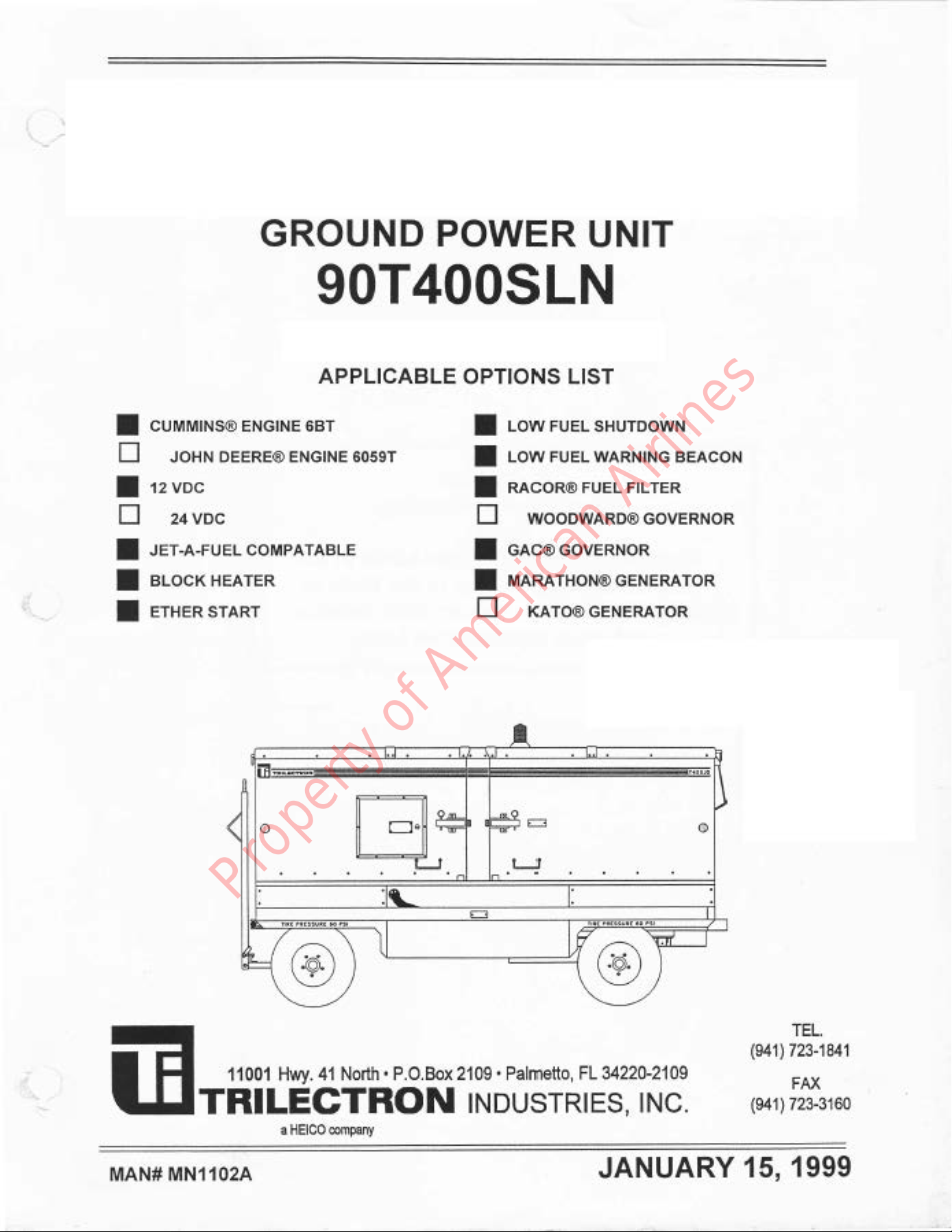
Operator
Property of American Airlines
Page 2

iE90T400sLN
lIIGROUND
OPERATION
POWER
CHAPTER
1
SECTION
2
UNIT
1. CONTROLS
Prior to operating
controls, indicators and
control location and
2. OPERATING PROCEDURES
A. Pre-Operationallnspection:
A PRIOR.TO.USE INSPECTION
TO ENSURE SAFE
PROCEDURES
THE
MENT.
(1)
(2)
(3)
(4)
(5)
(6)
(7)
AND INDICATORS
the
GPU,
functional description.
AND
Enclosure:
Towbar: Excessive movement.
Brakes: Check brakes for
Tires: Inspect tread wear, and check
Engine hoses
Radiator Coolant: Open forward canopy.
container.
Section 2-2, Servicing).
level: Open left front
Oil
the dip stick,
RELIABLE
LISTED BELOW MAY
Inspect
Coolant
personnel
procedures
MUST BE
for
and clamps:
should be
(Refer
to section 2-2,
become
must
described
in this section.
CAUTION
PERFORMED BEFORE
OPERATION
RESULT IN
obvious
access door.
defects, i.e., security
proper
Inspect for leaks
near the
OF THE
operation.
tire inflation
Servicing).
thoroughly
GPU. FAILURE TO
SEVERE DAMAGE
and security.
Observe level of coolant in overflow
full
line.
Service as required
Check that oil
familiar
Refer
EACH
of common
psig).
(60
level is at the full mark
with the operating
to figure 1 for illustrated
OPER,ATION
PERFORM
TO THE EQUIP-
hardware.
(Refer
to
on
January
Original
15, 1999
(8)
Fuel
level: Set IGNITION
Service
(9)
Engine Assembly:
leakage. lnspect valve
leakage.
Property of American Airlines
(10)
Fan Belt: Visually inspect
(11)
Air Filter
front
25 or higher
load.
(12)
Ether Start
operational readiness.
with fuel as necessary.
Visually
(Minder):
access door, under
is
(Optional):
Check
noted
switch to
inspect fuel lines and
cover, oil
for wear and cracking.
Filter Minder@ Indicator located to the left
the air filter assembly.
(engine
Check
pan,
running). Recheck when unit is running under
ether start supply cylinder
position,
ON
and cylinder
observe reading on fuel
fittings
Check
Replace
for
block for
belt for
air filter if a reading
evidence
evidence of oil
proper
installation for
of fuel
tension.
of the right
gauge.
of
1-2
Page 1
Page 3

iE90T400sLN
IJIGROUND
POWER UNIT
s-t
///1 \\ ///r \\
\wz
i
1-2
Page 2
ir.,
Fi
Hi
Hi iHil
Property of American Airlines
Hlgiiriiiii
Figure 1. Engine/Generator
ilis
ir
r;
Control
lli'lilll,l'lil,
i:
fl
ti
i
Panel
(Typical)
I il'
il
ll
t
ilii
f,:i
Single AC
-
Unit Shown
January 15,
Original
1999
Page 4

it90T400SLN
lIIGROUND
POWER
UNIT
Figure
1. Control
Item
,|
CONTROL
2 AC VOLTMETER:
3
FAULT INDICATORS
fault removes
4
AMMETER: Indicates
5 FUEL
6 OIL PRESSURE
7
FAULT INDICATORS - ENGINE
shutdown, i.e.,
(225"F).
8 IGNITION
I WATER
10 BATTERY VOLTMETER:
units
12V
11 HOURMETER:
START
12
13 FAULT
When
14 IGNITION SWTCH
PANEL
15
16 RUN/IDLE SWTCH: Two
for
oenerator ooeration.
17 AMMETER SWTCH
18 FREQUENCY METER: Shows
AC
19
LOAD
Used
GPU
AC
LOAD
4, Sect. 1-1)
20 AC LOAD CABLE OFF
AC
LOAD
put. (See
VOLTMETER S\MTCH: Selects either
21
voltmeter.
PANEL
LEVEL GAUGE: Indicates
ON INDICATOR
TEMPERATURE GAUGE:
and 20V on 24V units.
S\MTCH: Starts engine. Pushbutton,
LAMP
pressed
LIGHTS SWTCH:
CABLE ON
in conjunction with INTERLOCI(BY-PASS switch. \Mren
provides
CABLE 2 ON: Supplies AC
CABLE 2 OFF(Push-button)
figure
ASSEMBLY:
Shows
voltage fom the
GAUGE: lndicates engine
Low
Indicates totalengine run
TEST
while the iqnition switch is in the ON
momentary 28Y DC to aircraft connector
Sect. 1-l)
2,
generator
GENERATOR:
generator
pressure
oil
(Yellow):
lndicates battery voltage
(Pushbutton): \Mren
(ON/OFD:
Tums
position
(Rotary):
(Push-button):
(Pushbutton):
Panel
Gomponent
Description
Mounted
aircraft. Overvolts
(L-N)
amount of fuel
(Red):
(10
position
On
panel
switch. Controls engine
Measures cunent
qenerator
at front
(L-N)
output
Fault
output
lndicates
psi
min.);
Lights
Indicates engine
time.
pressed
supplies startino
liohts
output frequencv
Supplies
powerto
Removes output
Removes output
Line to Line or Line to Neutralvoltage
of electronic
voltage
indicators willilluminate
& Overload
cunent.
remaining
pressure.
oil
to operatorthe
Engine Overspeed
when the
condition.
momentary contact
while
On for nioht time ooeration.
of
powerto
AC
output Cable
tdentification
box assembly
(0-150
ENGINE CONTROL
watertemperature
unit is in
position.
phases
output
pins
powerfrom
power
volts).
red
stops
allvoltaoe
in fuel
tank.
protective
(2550
Do not
and controllino voltaqes
speed.
'1.2
(360-440H2).
2. Only on units
start unit if voltage
switch.
the RUN mode, it lights allfaults lamps.
it will
lioht onlv the enqine fault lamps.
IDLE
or 3.
Cable 1
pushed
ON is
E & F.
cablel
from cable
when a fault
oeneration.
system
RPM);
(225"F
position
(single
Engine
PO\ /ER switch is turned on.
(single
with INTERLOCK
with dualAC output
and dualAC
Only on units with dual AC
2.
measurements
has occuned.
caused
that
Over
max.).
is less than: 10V
enoine circuits.
to
for starting.
and
dual AC
output units).
to show on the
the engine
Temperature
RUN
output units).
(See
Each
on
position
setting,
figure
out-
2. OPERATINGPROCEDURES(Continued)
Property of American Airlines
B. Engine Start Procedures:
which
in
they
presented
are
The following steps
(See
Figure 1):
WARNING
DO NOT
ARCING
CONNECT LIVE POWER
MAY CAUSE
SERIOUS
CABLE TO AIRCRAFT.
INJURY, DEATH AND
EQUIPMENT.
January
15, 1999
Original
must be
SEVERE
DAMAGE
OR
performed
in the
ELECTRICAL
THE
TO
sequence
1-2
Page
3
Page 5

ffigOTAOOSLN
IIIGROUND
POWER
UNlr
Figure
NOTE:
2A.
Gauge
using
the
Figure
2. Control
Panel, Shown
in
the
Open
Position.
-^^
rtd)
\
w$-c
Control
Control Panel, Top
Property of American Airlines
lights
automatically
Panel Light
switch.
Left.
come ON
Figure
when
lgnition
28.
switch
Panel,
is ON.
Turn Panel
Top
Center.
Lights
on
1-2
Page
January
4
15, 1999
Original
Page 6

iH
.EI
e0T400sLN
GROUND
ffi:;*
w
W
Figure 2C. Control
PROLONGED
PERMANENT HEARING LOSS.
WHEN WORKING
BATTERY MUST BE
STARTING AND
EXPOSURE
IN CLOSE
(1)
(2)
ENGINE IGNITION
Set
canopy
Set IDLE/RUN switch
CONTROL.
mounted
FULLY
TO HAZARDOUS
PROXIMITY TO THIS
yellow
CHARGED
POWER
@"
'rtt'
Panel,
WARNING
NOISE
EAR PROTECTION
SWTCH
flashing
(16)
to IDLE.
CAUTION
TO
(14)
beacon will be
SUPPLY VOLTAGE
Right
LEVELS
DEVICES
EQUIPMENT.
to
UNIT
#,
W
W.
Side.
MAY
ON. IGNITION
illuminated.
RESULT IN
MUST
BE WORN
ON
FOR ENGINE
indicator
(8),
and
(3)
Observe the VOLTMETER
battery if a low voltage is indicated.
DO NOT HOLD
THIS DEPLETES THE
(4)
START
Press
come up to idle speed.
START
Property of American Airlines
IF LOW OR NO
OPERATION,
swrTcH
SEVERE
January
Original
15, 1999
IMMEDIATELY
(13)
TO
ENGINE DAMAGE.
(5)
OIL
30
PRESSURE IS INDICATED
OIL
OFF.
PRESSURE
psi
minimum at run speed.
gauge
CAUTION
BUTTON
BATTERY AND COULD DAMAGE
FATLURE TO COMPLY CAN
DEPRESSED FOR LONG
pushbutton
STOP
gauge
(12)
CAUTION
ENGINE BY
(6)
should read
(10)
on the
THE
for 1 - 2 seconds
AFTER 10.15
SETTING ENGINE IGNITION
RESULT rN
psi
10
Engine
PERIODS
minimum
Control Panel, charge
OF
STARTER.
to start engine.
SECONDS OF
pressure
TIME, AS
Engine
at idle
will
speed,
1-2
Page 5
Page 7

=.HgOT4OOSLN
NOT
DO
COMPLY
TO
lJf
(6)
WATER
warmed.
(7)
VOLTMETER
VDC
ALLOW THE
COULD
(8)
Let
(24
RESULT IN ENGINE
the engine idle for
cRouND PowER
TEMPERATURE
gauge
VDC
units)
ENGINE
TO IDLE FOR LONG PERIODS
gauge
(5):
Voltage should
.
CAUTION
minutes to warm engine.
2-3
(9)
indicates 170
DAMAGE.
uNtr
to 195'F
be at least
OF TIME. FAILURE
when engine
12 VDC
(12V
has
units) or
20
1-2
Page
6
Property of American Airlines
January
15, 1999
Original
 Loading...