

Page 1

Us
e
rs
Guide
MotherboardMotherboard
MotherboardMotherboard
Motherboard
LI545
Page 2

TT
TT
T
rademarksrademarks
rademarksrademarks
rademarks
TriGem is a registered trademark of TriGem Computer, Incorporated. Other
product names herein are for identification purposes only and may be trademarks
of their respective owners. TriGem disclaims any and all rights to those marks.
Intel is a registered trademark of Intel Corporation, MMX is a trademark of
Intel Corporation.
AMD is a registered trademark of Advanced Micro Devices, Incorporated.
Cyrix is a registered trademark of Cyrix Corporation.
PS/2 and VGA are trademarks of International Business Machines
Corporation.
Microsoft, MS-DOS, Microsoft Windows 95, Microsoft Windows NT are
registered trademarks of Microsoft Corporation.
Copyright(c) 1997 by TriGem Computer, Inc.
Disclaimer and Copyright NoticeDisclaimer and Copyright Notice
Disclaimer and Copyright NoticeDisclaimer and Copyright Notice
Disclaimer and Copyright Notice
All rights reserved. No part of this publication may be reproduced, stored in a
retrieval system, or transmitted, in any form or by any means, electronic,
mechanical, photocopying, recording, or otherwise, without the prior written
permission of TriGem Computer, Inc. No patent liability is assumed with respect
to the use of information contained herein. While every precaution has been taken
in the preparation of this publication, TriGem Computer, Inc. assumes no
responsibility for errors or omissions. There is no liability assumed for damages
resulting from the use of the information contained herein. Further, this
publication and features described herein are subject to change without notice.
Page 3

Safety Information
Safety Information
BatterBatter
BatterBatter
Batter
y Wy W
y Wy W
y W
arning Instructionarning Instruction
arning Instructionarning Instruction
arning Instruction
Caution
If battery is incorrectly replaced there poses a danger of explosion. Replace
battery only with the same or equivalent type recommended by the manufacturer.
Discard used batteries according to the manufacturer's instructions.
Attention
Il y a danger d'explosion s'il y a remplacement incorrect de la batterie. Remplacer
uniquement avec une batterie du meme type ou d'un type recommande par le
constructeur. Mettre au rebut les batteries usagees conformement aux
instructions du fabricant.
Vorsicht
Explosionsgefahr bei unsachgemaβ em Austausch der Batterie. Ersatz nur durch
denselben oder einen vom Hersteller empfohlenen ahnlichen Typ. Entsorgung
gebraushter Batterien nach Angaben des Herstellers.
FF
FF
F
use Wuse W
use Wuse W
use W
arning Instructionarning Instruction
arning Instructionarning Instruction
arning Instruction
Caution
For continued protection against risk of fire, replace only with same type and
rating of fuse. Disconnect input power before servicing. Only connect this
equipment to an earthed socket outlet.
Vorsicht
Vor jeder service-arbeit netzstecker ziehen! Apparatet ma kun tilkobles jordet
stikkontakt.
Attention
Debrancher avant d'ouvrir. Apparaten skall anslutas till jordat natuttag.
Atencion
Desconecte fuerza electrica antes del servicio. Laite on liitettava
suojakosketinistoraasian.
..
..
..
..
..
..
Page 4

Chapter 1 Motherboard DescriptionChapter 1 Motherboard Description
Chapter 1 Motherboard DescriptionChapter 1 Motherboard Description
Chapter 1 Motherboard Description
Features ............................................................................................................ 1-1
Motherboard Overview ..................................................................................... 1-3
Motherboard Connectors .................................................................................. 1-4
Power Supply Connector ......................................................................... 1-4
Front Panel Connectors............................................................................ 1-5
Rear Panel Connectors ............................................................................. 1-6
Board Expansion Connectors ................................................................... 1-9
FDD Connector........................................................................................ 1-9
Primary and Secondary E-IDE Connectors ............................................. 1-10
Chapter 2 Using the CMOS Setup ProgramChapter 2 Using the CMOS Setup Program
Chapter 2 Using the CMOS Setup ProgramChapter 2 Using the CMOS Setup Program
Chapter 2 Using the CMOS Setup Program
About the Setup Program ................................................................................. 2-1
Entering the Setup Program.............................................................................. 2-2
Exiting the Setup Program ................................................................................ 2-4
Setup Menu....................................................................................................... 2-5
Standard Setup Menu ............................................................................... 2-5
Advanced Setup Menu ............................................................................. 2-8
Chipset Setup Menu ................................................................................. 2-11
Power Control Setup Menu...................................................................... 2-12
PCI/PnP Setup Menu ............................................................................... 2-13
Peripheral Setup Menu ............................................................................. 2-15
Utility Menu ...................................................................................................... 2-17
Detect IDE ............................................................................................... 2-17
Color Set .................................................................................................. 2-18
CONTENTS
Page 5

Security Menu................................................................................................... 2-18
Supervisor/User ........................................................................................ 2-18
Default Menu .................................................................................................... 2-22
Original ..................................................................................................... 2-23
Optimal ..................................................................................................... 2-23
Chapter 3 Installing and Removing Board OptionsChapter 3 Installing and Removing Board Options
Chapter 3 Installing and Removing Board OptionsChapter 3 Installing and Removing Board Options
Chapter 3 Installing and Removing Board Options
Before You Begin .............................................................................................. 3-1
Installing and Removing the Microprocessor ................................................... 3-2
Installing the Microprocessor .................................................................. 3-2
Setting the Processor Speed .................................................................... 3-5
Removing the Microprocessor ................................................................. 3-5
Installing and Removing Memory Modules ...................................................... 3-7
Installing a Memory Module .................................................................... 3-8
Removing a Memory Module ................................................................... 3-8
Changing DIP Switches and Jumper Settings .................................................. 3-9
Locations of the DIP Switches and Jumpers .......................................... 3-9
DIP Switch and Jumper Settings ............................................................. 3-10
The Things to do in Post-installation ................................................................ 3-11
Chapter 4 Audio Drivers and ApplicationsChapter 4 Audio Drivers and Applications
Chapter 4 Audio Drivers and ApplicationsChapter 4 Audio Drivers and Applications
Chapter 4 Audio Drivers and Applications
Installing the Audio Drivers .............................................................................. 4-1
Installing and Using the Audio Applications...................................................... 4-6
Installing the Audio Applications .............................................................. 4-6
Using the Audio Applications ................................................................... 4-9
Chapter 5 Update on Installing Windows 95Chapter 5 Update on Installing Windows 95
Chapter 5 Update on Installing Windows 95Chapter 5 Update on Installing Windows 95
Chapter 5 Update on Installing Windows 95
Installing the USB Driver .................................................................................. 5-2
Installing the ACPI Driver ................................................................................ 5-3
Installing the DirectX-5 Driver ......................................................................... 5-5
Installing the AGP VxD Driver ......................................................................... 5-6
Page 6

Appendix A SpecificationsAppendix A Specifications
Appendix A SpecificationsAppendix A Specifications
Appendix A Specifications
Form Factor...................................................................................................... A-1
Processor.......................................................................................................... A-1
Main Memory ................................................................................................... A-1
Apollo VP3 AGPset and PCI/IDE Interface ..................................................... A-2
I/O features....................................................................................................... A-2
Six usable expansion slots ............................................................................... A-3
Other features ................................................................................................... A-3
Manufacturing Options ..................................................................................... A-3
Power Supply ................................................................................................... A-3
Appendix Appendix
Appendix Appendix
Appendix
BB
BB
B
Error and Information Messages Error and Information Messages
Error and Information Messages Error and Information Messages
Error and Information Messages
BIOS Error Messages ....................................................................................... B-1
BIOS Beep Codes ............................................................................................. B-2
Appendix Appendix
Appendix Appendix
Appendix
CC
CC
C
Motherboard Resources Motherboard Resources
Motherboard Resources Motherboard Resources
Motherboard Resources
DMA Channels .................................................................................................. C-1
Interrupts .......................................................................................................... C-2
Page 7

FiguresFigures
FiguresFigures
Figures
Figure 1. Motherboard overview ...................................................................... 1-3
Figure 2. Motherboard connectors ................................................................... 1-4
Figure 3. Connecting the power supply ........................................................... 1-5
Figure 4. Front panel connectors ..................................................................... 1-5
Figure 5. Rear panel connectors ....................................................................... 1-6
Figure 6. Connecting the keyboard................................................................... 1-6
Figure 7. Connecting the mouse....................................................................... 1-7
Figure 8. Connecting the USB devices ............................................................. 1-7
Figure 9. Connecting the serial device .............................................................. 1-8
Figure 10. Connecting the parallel device ......................................................... 1-8
Figure 11. Connecting the audio devices .......................................................... 1-9
Figure 12. Opening the ZIF socket................................................................... 3-2
Figure 13. Alignin the microprocessor on the ZIF socket ............................... 3-3
Figure 14. Inserting the microprocessor in the ZIF scoket ............................. 3-3
Figure 15. Connecting the heatsink fan connector ........................................... 3-4
Figure 16. Removing the heatsink fan connector ............................................. 3-5
Figure 17. Removing the microprocessor from the ZIF socket ...................... 3-6
Figure 18. Installing a memory module ............................................................ 3-8
Figure 19. Removing a memory module .......................................................... 3-8
Figure 20. DIP switches and jumpers .............................................................. 3-9
Page 8

1-1
Motherboard Description
Motherboard Description
Motherboard Description
FF
FF
F
eatureseatures
eatureseatures
eatures
The motherboard supports the following features:
Smallest PCB size in the ATX form factor
Intel Pentium P54C(S), Intel Pentium P55C-MMX, AMD K5/K6, or Cyrix
6x86/6x86MX
Three 168 pin DIMM sockets, support up to 384 MB of synchronous DRAM
(SDRAM) memory and support unbuffered EDO DRAM
512 KB of synchronous Pipeline Burst SRAM external cache
Two built-in PCI bus Enhanced IDE hard disk drive controllers, each channel
supports up to two hard disk drives or CD-ROM drives
VT82C597 Single chip north bridge (PCI/AGP/Memory controller)
VT82C586B PCI/ISA/IDE Xcelerator
IT8661F super I/O controller
CX4236B audio controller and CS9236 wavetable (Ready for CS4235 with 3D)
Three 32-bit PCI slots, one 16-bit ISA slot, and one shared PCI/ISA slot
One AGP (Accelerated Graphics Port) slot
Chapter 1
This chapter describes the major features of your motherboard.
Page 9

1-2
Motherboard Description
NoteNote
NoteNote
Note
The Accelerated Graphics Port (AGP) is a high-performance interconnect for
graphic-intensive applications, such as 3D applications. AGP is independent of
the PCI bus and is intended for exclusive use with graphical-display devices.
System and video BIOS shadow RAM
Plug-and-Play (PnP) BIOS feature
A built-in PS/2 style keyboard connector and a built-in PS/2 compatible mouse
connector
Two Universal Serial Bus (USB) interfaces
Two serial ports and one parallel port
One Joystick and three audio I/O interface port
The following are manufacturing options:
Wake up on LAN connector
System chassis intrusion
Management extension hardware
NoteNote
NoteNote
Note
The motherboard has two USB ports; one USB peripheral can be connected to
each port. For more than two USB devices, an external hub can be connected
to either port. The motherboard fully supports the universal host controller
interface (UHCI) and uses UHCI-compatible software drivers.
NoteNote
NoteNote
Note
The Wake up on LAN header allows the computer to wake from sleep mode, or
power on when a call is received on a network device, such as a LAN.
The first incoming call powers up the computer. A second call must be made to
access the computer.
Page 10
1-3
Motherboard Description
Motherboard OverMotherboard Over
Motherboard OverMotherboard Over
Motherboard Over
viewview
viewview
view
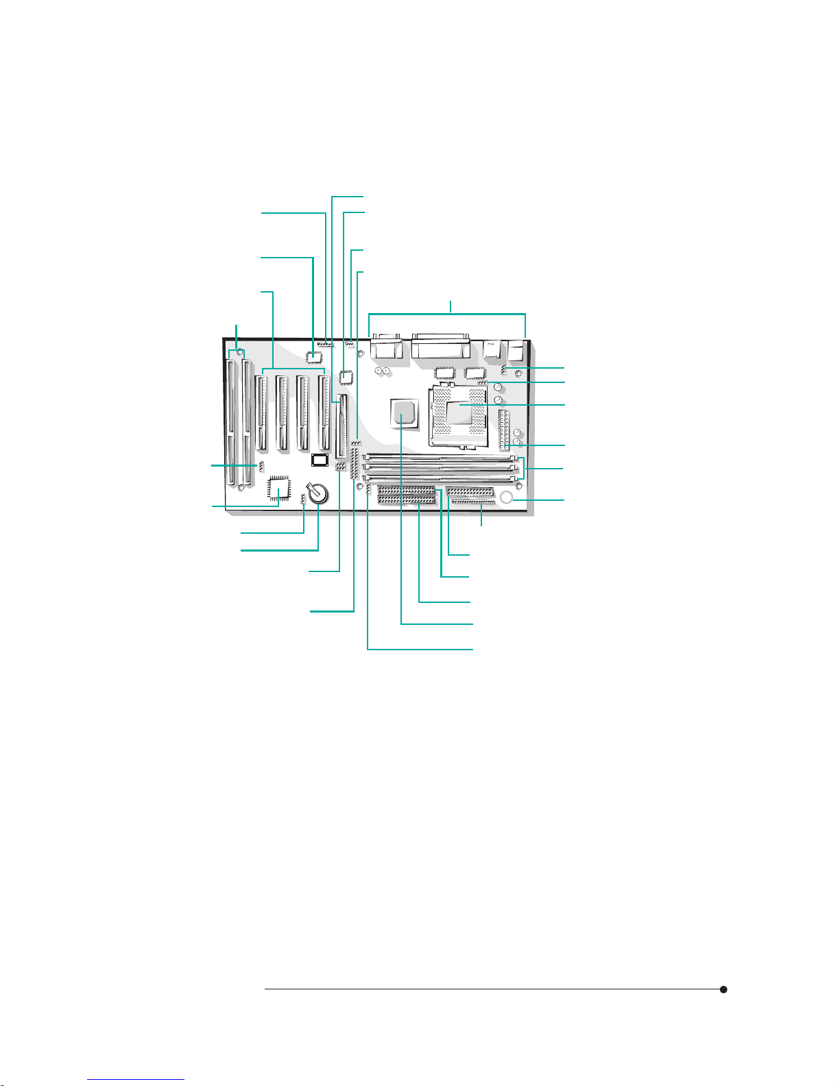
Figure 1. Motherboard overview
ISA connectors
Back Panel I/O connectors
Microprocessor
socket (socket 7)
CPU voltage jumper (J11)
CPU fan connector
Power supply connector
DIMM sockets
Speaker
Front panel connectors
FDD connector
Battery
Wake up LAN
connector
VIA VT82C586B
CMOS clear jumper
DIP switches (SW1)
Main clock frequency jumper (J6)
Board type selection
jumper (J8 and J10)
Seconary E-IDE connector
VIA VT82C597
Aging jumper (J12)
Primary E-IDE connector
PCI connectors
IT8661F super
I/O controller
CX4236B audio
controller (optional)
AGP connector
CD audio connector
IrDA connector
Page 11
1-4
Motherboard Description
Motherboard ConnectorsMotherboard Connectors
Motherboard ConnectorsMotherboard Connectors
Motherboard Connectors
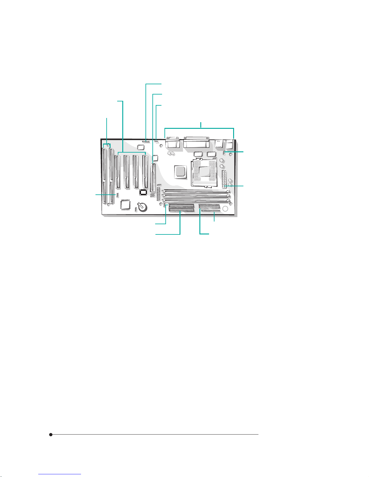
Figure 2. Motherboard connectors
Power Supply Connector
The power supply converts AC power from a wall outlet to the DC voltages
required by motherboard and devices in your system. The power supply has a
large motherboard connector and several internal device (hard disk, CD-ROM,
and floppy disk drive, etc.) connectors.
The power supply should match the physical configuration of the chassis. Before
attaching all components, make sure the proper voltage has been selected. Power
supplies often can run on a wide range of voltages and must be set (usually via a
switch) to the proper range.
ISA connectors
Back Panel I/O connectors
CPU fan connector
Power supply connector
Front panel connectors
FDD connector
Wake up LAN
connector
Seconary E-IDE connector
Primary E-IDE connector
PCI connectors
AGP connector
CD audio connector
IrDA connector
Page 12
1-5
Motherboard Description
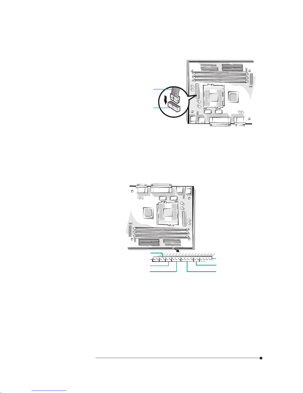
Figure 3. Connecting the power supply
Front Panel Connectors
The motherboard has connectors for controls and indicators typically located on
the front panel of the computer.
Figure 4. Front panel connectors
Power supply cable
Power supply
connector
You can connect the power supply cable to the power connector on the
motherboard.
Power LED
Suspend/Resume
Reset (optional)
Power button
Speaker
Key lock
HDD LED
Page 13
1-6
Motherboard Description
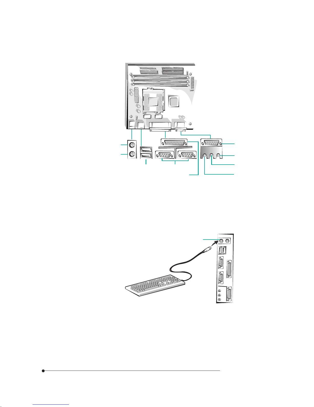
Rear Panel Connectors
Figure 5. Rear panel connectors
Keyboard Connector
Your system's PS/2 style keyboard plugs into the keyboard connector.
Figure 6. Connecting the keyboard
Keyboard connector
Mouse
USB ports Serial ports
MIDI/Game port
SPK jack
Line-in jack
MIC jack
Parallel port
Keyboard
Page 14
1-7
Motherboard Description
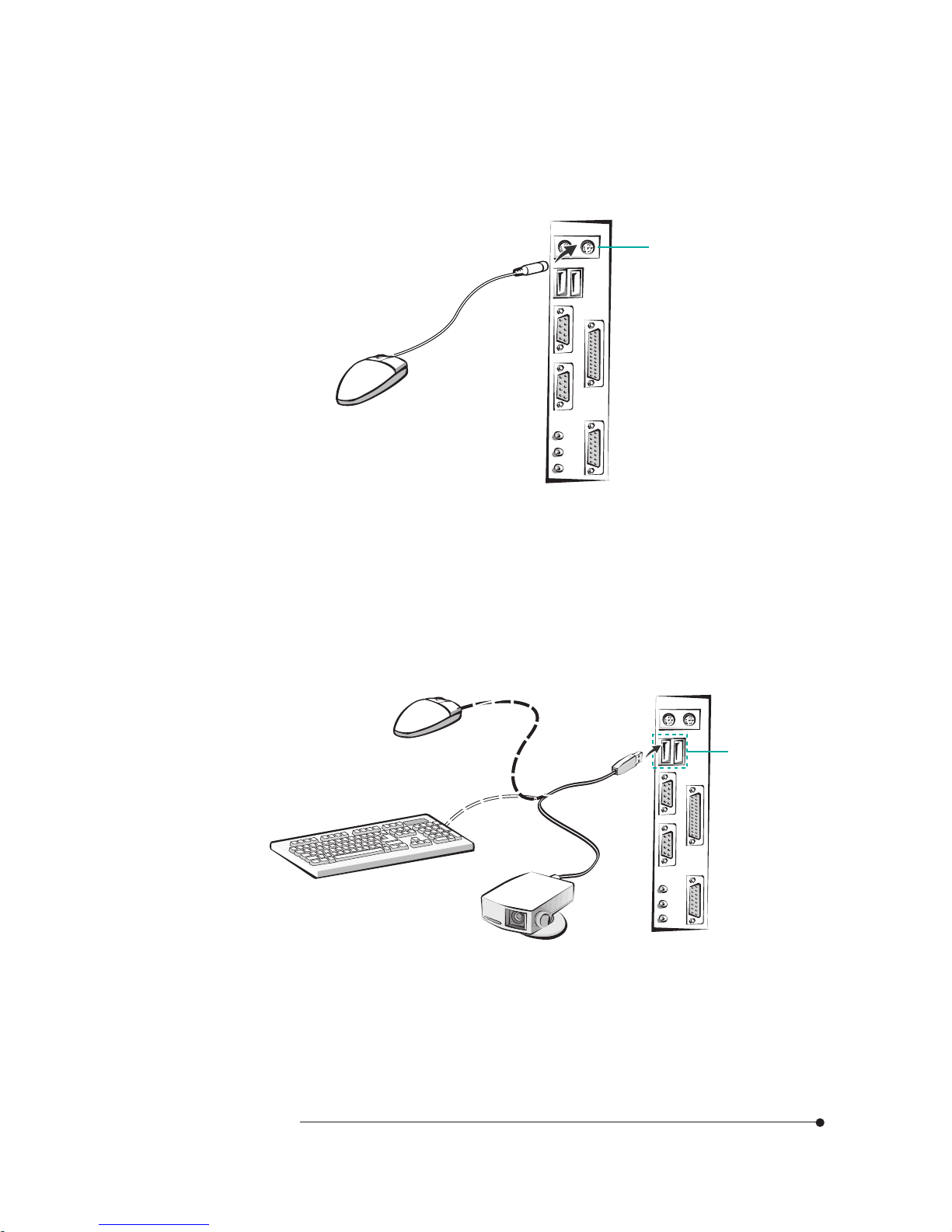
Mouse Connector
Your system's PS/2 compatible mouse plugs into the mouse connector.
Figure 7. Connecting the mouse
USB Connectors
You can connect any USB compliant devices to either of the USB connectors.
USB devices include low-speed peripherals such as microphone, digital joystick,
and speaker.
Figure 8. Connecting the USB devices
Mouse connector
USB connectors
Page 15
1-8
Motherboard Description
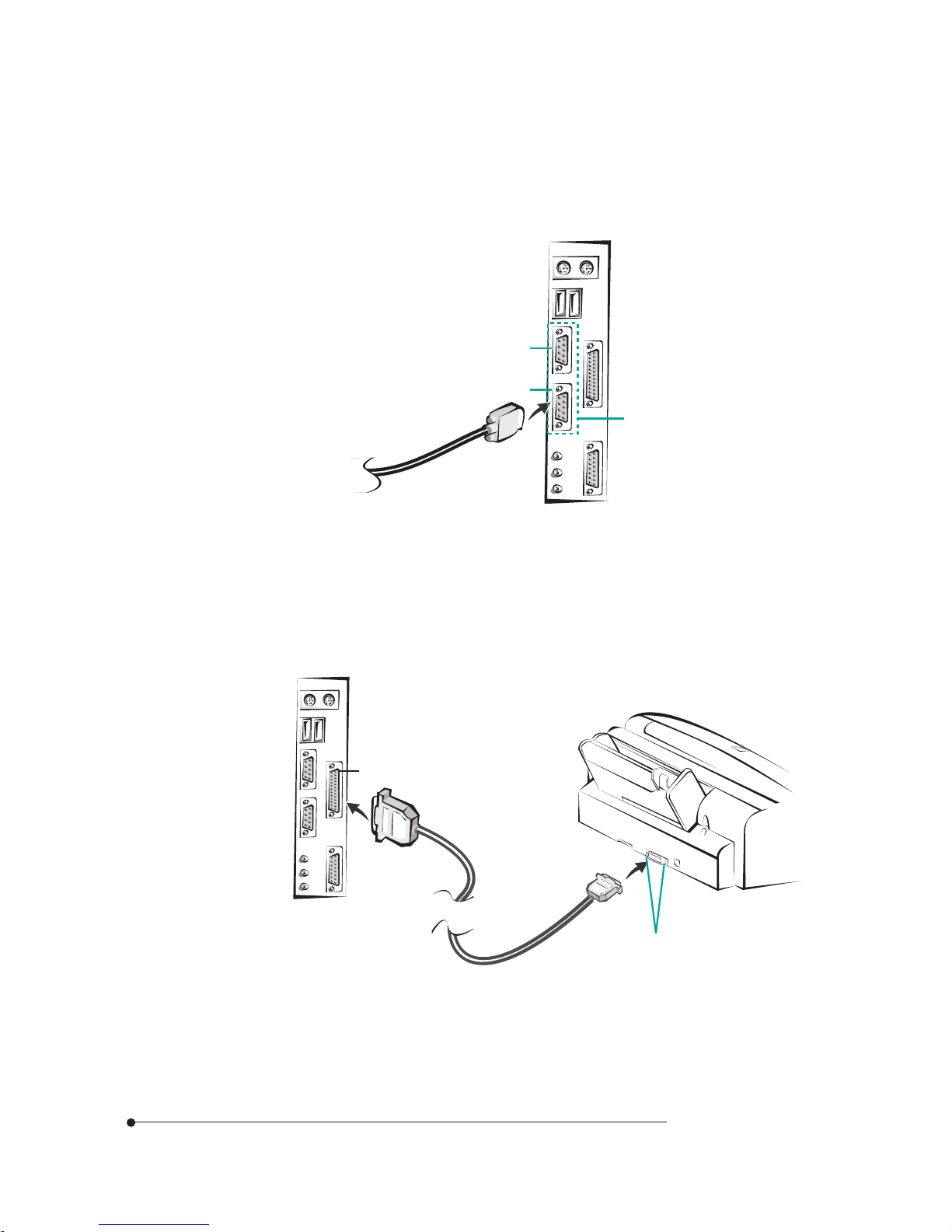
Serial Port (COM1, 2) Connectors
You can connect a serial device, such as an external modem and printer, to the
serial port connectors.
Figure 9. Connecting the serial device
Parallel Port (LPT1) Connector
You can connect a parallel device, such as a printer, to the parallel port.
Figure 10. Connecting the parallel device
Parallel port connector
Clips
Serial port connectors
COM 1
COM 2
Page 16
1-9
Motherboard Description
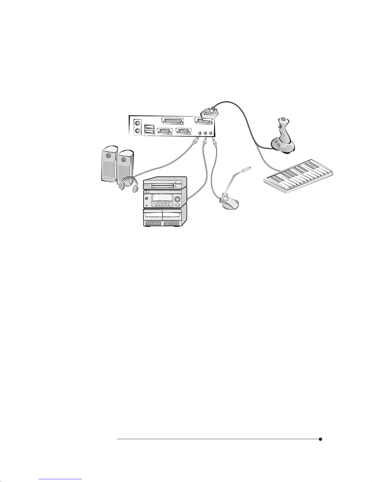
Audio Connectors (Optional)
Your motherboard has three audio jacks (SPK, Line-in, and MIC) and one MIDI/
Game port connector. Your optional audio devices and MIDI/Game device are
connected to these connectors, as shown below.
Figure 11. Connecting the audio devices
Board Expansion Connectors
There are three PCI slots, one ISA slot, and one shared slot (for a PCI or ISA
card). The PCI bus supports up to four bus masters through the four PCI
connectors.
FDD Connector
You can connect your diskette drive(s) to the diskette drive connector on the
motherboard by using the diskette drive ribbon cable. The diskette drive ribbon
cable has two connectors for diskette drives in general. After connecting the one
end of the diskette drive ribbon cable to the motherboard, attach the connector(s)
on the other end to the diskette drive(s).
Joystick
Audio device
Speaker
Microphone
MIDI keyboard
Page 17

1-10
Motherboard Description
Primary and Secondary E-IDE Connectors
Your motherboard has two built-in PCI E-IDE interfaces (primary and
secondary). Each interface supports up to two IDE drives (master and slave).
After connecting the one end of the IDE ribbon cable to the primary or secondary
E-IDE connector on the motherboard, connect the connector(s) at the other end
to your IDE drive(s) such as the hard disk drive or CD-ROM drive.
If you install two hard disks by using one IDE ribbon cable, you must configure
the second drive to slave mode by setting its jumper accordingly. See the manual
of your hard disk for the jumper settings.
You may configure two hard disk drives to be both masters by connecting one
ribbon cable (one hard disk drive will be attached to it) to the primary E-IDE
connector and another ribbon cable (the other hard disk drive will be attached to
it) to the secondary IDE connector. When you install one operating system on an
IDE drive and another on the other IDE drive, you can select the boot device
through the Setup program.
The BIOS in the motherboard supports boot up from IDE CD-ROM drive,
floptical drive, SCSI drive or network drive. So, you can select a CD-ROM drive
or floptical drive as a boot device by setting the 1st/2nd /3rd Boot Device option
to CD-ROM or Floptical in the Advanced Setup menu of the Setup program.
NOTE : The hard disk drive controller on the motherboard supports Ultra DMA/
33, a DMA data transfer protocol for hard disk drives. This allows DMA
commands to transfer data at a maximum burst rate of 33MB/sec. Both the
controller and the hard disk must be capable of supporting Ultra DMA/33 in order
to enable this feature.
Page 18

2-1
Using the Setup Program
Using the CMOS Setup Program
Using the CMOS Setup Program
About the Setup ProgramAbout the Setup Program
About the Setup ProgramAbout the Setup Program
About the Setup Program
This chapter explains how to use the CMOS Setup program. You can use the
Setup program to change the computer's configuration information and boot-up
sequence, etc.
The Setup program is stored in the computer's read only memory (ROM), so you
can run the program at any time when you turn on or reset your computer. You
need not insert a diskette or access the hard disk.
The Setup program lets you verify or change the followings:
On the Setup menu, you can set up and modify some of the basic options of a
system, such as time, date, diskette drives and hard disk drives.
On the Utilities menu, you can perform system functions.
On the Security menu, you can specify password that can be used to limit
access to the system.
On the Default menu, you can select a group of settings for all CMOS Setup
options.
The configuration you define through the Setup program is stored in a special
area of memory called CMOS RAM. The battery on the main board backs up this
memory, so the memory is not erased when you turn off or reset the computer.
Whenever you reboot the computer, it checks the settings, and if it discovers a
difference between the information in the CMOS RAM and its actual hardware
configuration, it prompts you to run the Setup program.
Chapter 2
Page 19

2-2
Using the Setup Program
NoteNote
NoteNote
Note
For reference purposes, you should write down the current Setup settings.
When you make changes to the settings, update this record.
You may see a message such as the following:
CMOS Settings Wrong
Press F1 to Resume
If this happens, just press F1 to run the Setup program and then correct the
setting.
Entering the Setup ProgramEntering the Setup Program
Entering the Setup ProgramEntering the Setup Program
Entering the Setup Program
To enter the Setup program, turn the computer on and press <Del> when you see
the message:
"Hit DEL if you want to run SETUP."
As soon as you see this message, hit the DEL key. If you do not press DEL key
quickly, the computer starts loading the operating system and you will not be able
to run the Setup program. If this happens, reset the computer again.
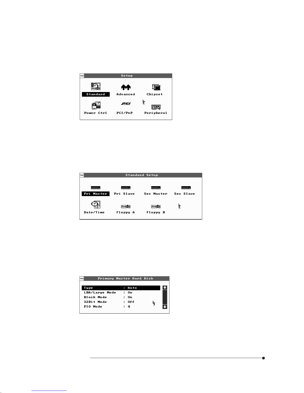
When you enter the Setup program, you will see the Setup menu.
Page 20

2-3
Using the Setup Program
You can use your keyboard or mouse to select the options.
The mouse functions are click (change or select both global and current field) or
double click (perform an operation in the selected field).
The following list provides an overview of function keys in the Setup program.
Setup Key
Tab Moves to the next window or field.
Description
←, →, ↑, or ↓
Move to the next field to the right, left, above, or below.
Enter
Selects the current field.
+
Increases a value.
-
Decreases a value.
Esc
Closes the current operation and return to previous level.
PgUp
Returns to the previous page.
PgDn Advances to the next page.
Home
Returns to the beginning of the text.
End
Advances to the end of the text.
Alt-H
Accesses a help window. It describes the keys available in Setup.
Alt-Spacebar Exits System Setup
Alphabetic keys
A to Z are used in your keyboard.
Numeric keys
0 to 9 are used in either the numeric keys along the top of the
keyboard or the numeric keypad.
The Setup program is composed of four windows that contain several icons. An
information line at the bottom of the menu displays simple explanations for each
option.
Page 21
2-4
Using the Setup Program
Exiting the Setup ProgramExiting the Setup Program
Exiting the Setup ProgramExiting the Setup Program
Exiting the Setup Program
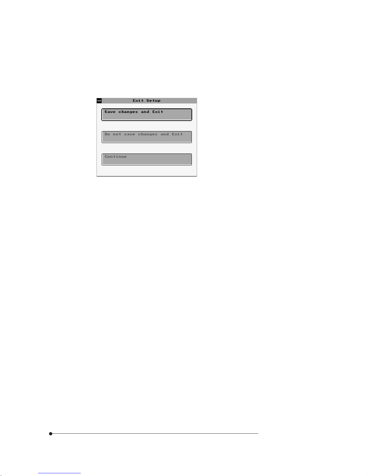
To exit the Setup program, press Alt and Spacebar keys simultaneously. If you
press these keys, you can see the following window.
To save the settings and exit, select Save changes and Exit. The system reboots
with your new settings.
If you want to exit the Setup program without saving your settings, select Do not
save changes and Exit. The system reboots with your original settings.
To return to the Setup menu to make corrections, select Continue.
If you saved your changes or quitted without saving the settings, the Setup
program resets the system and the computer performs its power on diagnostic
tests.
If your computer detects a problem in your Setup configuration, you may see an
error message and a prompt to run the Setup program when it is rebooting.
Follow the instructions on the screen to run the Setup program and correct the
problem.
Page 22
2-5
Using the Setup Program
Standard Setup Menu
Standard Setup options are displayed by choosing the Standard icon from the
BIOS Setup menu. All Standard Setup options are described below.
Setup MenuSetup Menu
Setup MenuSetup Menu
Setup Menu
The Setup menu has 6 icons, each of which contains a submenu.
Pri Master/Pri Slave/Sec Master/Sec Slave
Choose these icons to configure the hard disk drive named in the option. When
you click on an icon, the following parameters are listed: Type, LBA/Large Mode,
Block Mode, 32Bit Mode, and PIO Mode.
Page 23

2-6
Using the Setup Program
Type
You can choose the appropriate hard disk and CD-ROM drives type for yours.
Type : The number for a drive with certain identification parameters.
Cyl : The number of cylinders in the disk drive.
HD : The number of heads.
WP : The size of a sector gets progressively smaller as the track diameter
diminishes. Yet each sector must still hold 512 bytes. Write precompensation
circuitry on the hard disk compensates for the physical difference in sector
size by boosting the write current for sectors on inner tracks. This parameter
is the track number where write precompensation begins.
Sec : The number of sectors per track. MFM drives have 17 sectors per
track. RLL drives have 26 sectors per track. ESDI drives have 34 sectors per
track. SCSI and IDE drives have more sectors per track.
Size (MB) : The formatted capacity of the drive. (Size = Number of heads ×
Number of cylinders × Number of sectors per track × 512 bytes per sector.)
User : If you are configuring a drive with drive parameters that do not match
drive types, you can select the User in the Type field. You must then enter the
drive parameters on the screen that appears.
AUTO : If the hard disk drive to be configured is an IDE drive, select the
appropriate drive icon (Pri Master, Pri Slave, Sec Master, or Sec Slave). Select
the IDE Detect icon to automatically detect all drive parameters.
BIOS automatically detects the IDE drive parameters (including ATAPI
CD-ROM drives) and displays them. Click on the OK button to accept these
parameters or you can set the parameters manually if you are absolutely
certain that you know the correct IDE drive parameters.
CDROM : Select the appropriate drive icon (Pri Master, Pri Slave, Sec Master,
or Sec Slave). Choose the Type parameter and select CDROM. You can boot
the computer from a CD-ROM drive. You can also choose Auto and let BIOS
will automatically set the correct drive parameters.
Floptical : If a floptical drive is connected to the IDE connector, select
FLOPTICAL for the drive. You can boot the computer from the floptical
drive.
Page 24
2-7
Using the Setup Program
LBA/Large Mode
To use the IDE drives with capacities greater than 528 MB, set this option to On.
The settings are On and Off.
Block Mode
To use the IDE drives that use Block transfer Mode, set this option to On. The
settings are On and Off.
32Bit Mode
Set it to On to support IDE drives that permit 32-bit accesses. The settings are
On and Off.
PIO Mode
This option selects the IDE Programmed I/O mode. PIO programming also
works with ATAPI CD-ROM drives. The settings are Auto, 0, 1, 2, 3, 4, and 5.
Choose Auto to allow BIOS to automatically find the PIO mode that the IDE drive
being configured uses. If you select 0-5 you must make absolutely certain that
you are selecting the PIO mode supported by the IDE drive being configured.
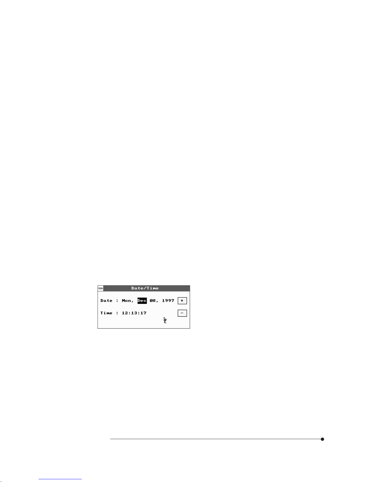
Date/Time
Select the Date/Time option to change the date or time. The current date and time
are displayed. Enter new values through the displayed window.
Page 25

2-8
Using the Setup Program
Floppy Drive A, B
Choose the Floppy Drive A or B icon to specify the floppy drive type. The
settings are Not Installed, 360 KB 5 1/4, 1.2 MB 5 1/4, 720 KB 3 1/2, 1.44 MB 3
1/2, and 2.88 MB 3 1/2.
Advanced Setup Menu
Advanced Setup options are displayed by choosing the Advanced icon from the
BIOS Setup main menu. All Advanced Setup options are described in this section.
Page 26

2-9
Using the Setup Program
1st/2nd/3rd Boot Device
Each menu allows you to select the first, second and third devices the computer
checks when it looks for the operating system. The settings available for the 1st
Boot Device option are Disabled, IDE-0, IDE-1, IDE-2, IDE-3, Floppy,
FLOPTICAL, CDROM, and SCSI. The settings available for 2nd Boot Device
and 3rd Boot Device are Disabled, IDE-0, Floppy, FLOPTICAL, and CDROM.
S.M.A.R.T. for Hard Disks
S.M.A.R.T. (Self-Monitoring, Analysis and Reporting Technology) predicts the
hardware failure. This technology is developed to manage the reliability of the
hard disk. The settings are Disabled and Enabled.
Quick Boot
Set it to Enabled to instruct BIOS to boot quickly when the computer is powered
on. The settings are:
Disabled : BIOS test all system memory. BIOS waits up to 40 seconds for a
READY signal from the IDE hard disk drive. BIOS waits for .5 seconds after
sending a RESET signal to the IDE drive to allow the IDE drive time to get
ready again.
Enabled : BIOS does not test system memory above 1 MB. BIOS does not
wait up to 40 seconds for a READY signal from the IDE hard disk drive. If a
READY signal is not received immediately from the IDE drive, BIOS does not
configure that drive. BIOS does not wait for .5 seconds after sending a
RESET signal to the IDE drive to allow the IDE drive time to get ready again.
BootUp Num-Lock
This option determines the beginning state of the Num Lock feature on your
keyboard, when system is turned on or reset. The settings are On and Off.
Floppy Drive Swap
If you are using two diskette drives, you can easily switch between drives A and
B. For example, if you are using a 1.44MB diskette drive as drive A and a 1.2MB
diskette drive as drive B, you can switch the drives vice versa by enabling the
option. When you set the option, you must switch between the settings for both
drives from the Floppy A and Floppy B options in the Standard Setup menu. The
settings are Disabled and Enabled.
Page 27

2-10
Using the Setup Program
Floppy Access Control
This option sets read/write access for all attached diskette drives. The settings are
Normal and Read Only. Normal means read/write access for drives.
If you select Read Only for each option, you can read a diskette and copy data
from it, but you cannot store new data on it or delete any files it contains.
PS/2 Mouse Support
If you enable this option, you can use a PS/2 mouse. The settings are Disabled
and Enabled.
Primary Display
This option lets you define the type of adapter you are using for your primary
display. The settings are Absent, VGA/EGA, CGA40X25, CGA80X25, and Mono.
Password Check
This option sets the type of password protection. The settings are Setup and
Always. If you select Setup, every time you run the Setup program, the computer
checks your password. Once you set password, you should enter your password
whenever you run the Setup program.
If you select Always, every time you run the Setup program or turn on or reset
the computer, it checks your password.
Boot To OS/2
If your system has above 64MB of main memory, set this option to Yes to allow
the system to run OS/2 Warp version 3.0 properly. The settings are Yes and No.
External Cache
The option sets the type of caching algorithm for L2 external cache memory. The
settings are Disabled and Enabled.
C000 / C400, 16K Shadow
These options allow you to shadow the contents of video ROM listed on the
screen to the system's RAM. The settings are Disabled and Enabled.
Page 28

2-11
Using the Setup Program
C800 / CC00 / D000 / D400 / D800 / DC00, 16K Shadow
These options allow you to shadow the contents of the adapter ROM listed on the
screen to the system's RAM. The settings are Disabled and Enabled.
Chipset Setup Menu
If you select the Chipset icon from the Setup main menu, the Chipset Setup menu
is displayed.
USB Function
To use the USB function, set this option to Enabled. The settings are Enabled and
Disabled.
AGP
This option is automatically set by BIOS. When you install the AGP card in the
system, BIOS detects it and sets this option to Enabled.
Graphic Aperture Size
The base of the Graphics Aperture can be anywhere in the system virtual address
space on an address boundary determined by the aperture size. This option is only
available if the setting for the AGP option is Enabled.
AGP-2X Mode
The AGP protocol provides Qword access granularity. Qword transfers normally
take two clock cycles in the 1X mode. Likewise, sideband address commands
normally take two clocks per each 16bit command. This option is only available if
the setting for the AGP option is Enabled.
Page 29

2-12
Using the Setup Program
Power Control Setup Menu
If you select the Power Ctrl icon from the Setup main menu, the Power Control
Setup menu is displayed.
Power Management / APM
Set the option to Enabled to enable the power management and APM (Advanced
Power Management) features. If you set Disabled for the option, you will not see
any options in the Power Control Setup menu. The settings are Disabled and
Enabled.
Instant Off Support
When the option is set to Enabled, normally pressing the power button after
power-on self-test makes the system immediately turned off. When the option is
set to Disabled, you should press the power button for more than 4 seconds to
turn off the system after finishing power-on self-test. The settings are Enabled
and Disabled.
Wake Up On LAN
If you want to use Wake Up and Power On by a LAN, set this option to Enabled.
Page 30

2-13
Using the Setup Program
Video Power Down Mode
This option specifies the power management state that the video subsystem
enters after the specified period of display inactivity has expired. The settings are
Disabled, Standby, or Suspend.
Suspend Time Out
The option specifies the length of the period of system inactivity for going into
suspend mode. When the specified period expires, the computer enters suspend
mode, beeping twice. If there are activities of devices described below, the
computer exits the suspend mode. The settings are 1mins, 2mins, 3mins, 10mins,
15mins, 30mins, and 60mins.
IRQ 3, 4, 5, 7, 9, 10, 11, 13, 14, and 15
These options enable event monitoring. When the computer is in a power saving
mode, activity on the named interrupt request line is monitored by AMIBIOS.
When any activity occurs, the computer enters Full On mode. Each of these
options can be set to Monitor or Ignore.
PCI/PnP Setup Menu
If you select the PCI/PnP icon from the Setup main menu, the PCI/PnP Setup
menu is displayed.
Green PC Monitor Power State
This option specifies the power management state that the Green PC-compliant
video monitor enters after the specified period of display inactivity has expired.
The settings are Disabled, Off, Standby, and Suspend.
Page 31

2-14
Using the Setup Program
Plug and Play Aware O/S
The option enables the computer to boot with an operating system capable of
managing Plug and Play add-in cards. Set it to Yes if the operating system (such
as Windows 95) installed in the computer follows the Plug and Play specification.
AMIBIOS only detects and enables PnP ISA adapter cards that are required for
system boot. The Windows 95 operating system detects and enables all other
PnP-aware adapter cards. Windows 95 is PnP-aware. Set the option to No if the
operating system (such as DOS, OS/2, Windows 3.X) does not use PnP. You
must set this option correctly, or PnP-aware adapter cards installed in the
computer will not be configured properly. The settings are No and Yes.
PCI Latency Timer (PCI Clocks)
This option sets the length of time (measured in the number of PCI clock cycles)
that a device on the PCI bus can hold the bus when another device has requested
the bus. The clock choices include every 32nd value between 32 and 248 clocks.
The settings are 32, 64, 96, 128, 160, 192, 224, and 248.
PCI VGA Palette Snoop
The option controls the ability of a primary PCI graphics controller to share a
common palette with an ISA add-in video card. The settings are Disabled and
Enabled.
Assign IRQ to PCI VGA
This option allows you to assign IRQ to PCI VGA card.
DMA Channel 0, 1, 3, 5, 6, and 7
These options allow you to reserve DMAs for legacy ISA adapter cards. The
settings are PnP and ISA.
IRQ 3, 4, 5, 7, 9, 10, 11, 14, and 15
These options set the status of the IRQ. If these interrupts are available for use
by a PCI/PnP add-in card, the interrupts are assigned for the computer to use. If
the computer contains an ISA agent that uses one of these interrupts, select ISA
for that interrupt. The settings are PCI/PnP and ISA.
Page 32

2-15
Using the Setup Program
Peripheral Setup Menu
The Peripheral Setup menu is displayed if you select the Peripheral icon from the
Setup main menu.
OnBoard Sound
Set this option to Enabled to use the onboard audio subsystem in the
motherboard. The settings are Enabled and Disabled. This option doesns appear
if your motherboard has not built-in audio system.
OnBoard FDC
Set this option to Enabled to enable the built-in diskette drive controller. If you
install another FDC card, disable this option. The settings are Auto, Disabled, and
Enabled.
OnBoard Serial Port 1 and 2
These options specify the base I/O port addresses of built-in serial ports 1 and
2(optional). The settings are Auto, Disabled, 3F8h, 2F8h, 3E8h, and 2E8h.
OnBoard Parallel Port
It specifies the base I/O port address of the built-in parallel port. The settings are
Auto, Disabled, 378, 278, and 3BC.
Page 33

2-16
Using the Setup Program
Parallel Port Mode
It specifies the parallel port mode. ECP and EPP are both bi-directional data
transfer schemes that adhere to the IEEE P1284 specifications. The settings are:
Normal : Use this option to operate the parallel port in Standard Parallel Port
(SPP) mode and bi-directional mode.
EPP : The parallel port can be used with devices that adhere to the Enhanced
Parallel Port (EPP) specification. EPP uses the existing parallel port signals to
provide asymmetric bi-directional data transfer driven by the host device.
ECP : The parallel port can be used with devices that adhere to the Extended
Capabilities Port (ECP) specification. ECP uses the DMA protocol to achieve
transfer rates of approximately 2.5 Mbs. ECP provides symmetric bidirectional communications.
Parallel Port IRQ
It is only available when the On Board Parallel Port option is not set to Auto. The
settings are 5 and 7.
Parallel Port DMA Channel
It is only available if the setting for the Parallel Port Mode option is ECP. The
settings are 0, 1, and 3.
VIA OnBoard PCI IDE
The option allows you to set the built-in IDE controller you want to use. The
settings are Disabled, Primary, Secondary, and Both.
Page 34

2-17
Using the Setup Program
Utility MenuUtility Menu
Utility MenuUtility Menu
Utility Menu
There are 2 icons in the Utility menu.
After SETUP detects all IDE drives, the hard disk drive type will be forced to be
User and the CD-ROM drive type will be forced to be CDROM.
Detect IDE
If an IDE-type hard disk drive, a CD-ROM drive, or a floptical drive is connected
to the primary or secondary IDE controller, this option allows for automatic
detection of the hard disk drive or CD-ROM drive type. Once SETUP detects the
type of the hard disk or CD-ROM drive installed, it will display the relative
information.
Page 35

2-18
Using the Setup Program
Color Set
This option allows you to change the color of the System Setup screen. The
settings are Sky, Army, Pastel, and LCD.
Security MenuSecurity Menu
Security MenuSecurity Menu
Security Menu
Supervisor / User
These two options make it possible to restrict access to the Setup program and to
restrict who can boot the computer by enabling you to set passwords for two
different access modes: Supervisor mode and User mode.
A Supervisor password and a User password can be set for the Setup program
and for booting the computer.
Supervisor mode has full access to all the Setup options whereas User mode has
limited access to the options. Setting separate Supervisor and User passwords
enables a system supervisor to restrict who can change critical Setup values.
When you run the Setup program by entering your User password, you can
change the three items only: Advanced, User, and Color Set.
If you set both the Supervisor and User passwords, you must set the Supervisor
password first. Once both are set, you can enter either the Supervisor password
or the User password to access the Setup or the computer.
Three icons appear in the Security menu.
Page 36
2-19
Using the Setup Program
The table shows the effects of setting the Supervisor and User passwords.
Password
set
Password
during boot
Password to enter the
Setup Program
Supervisor
mode
User mode
Neither
None None Can change all
options
Can change all
options
Supervisor and
User set
Supervisor or
User
Supervisor or User Can change all
options
Can change all
options
Can change a
limited number of
options
Supervisor
only
Supervisor Supervisor
-
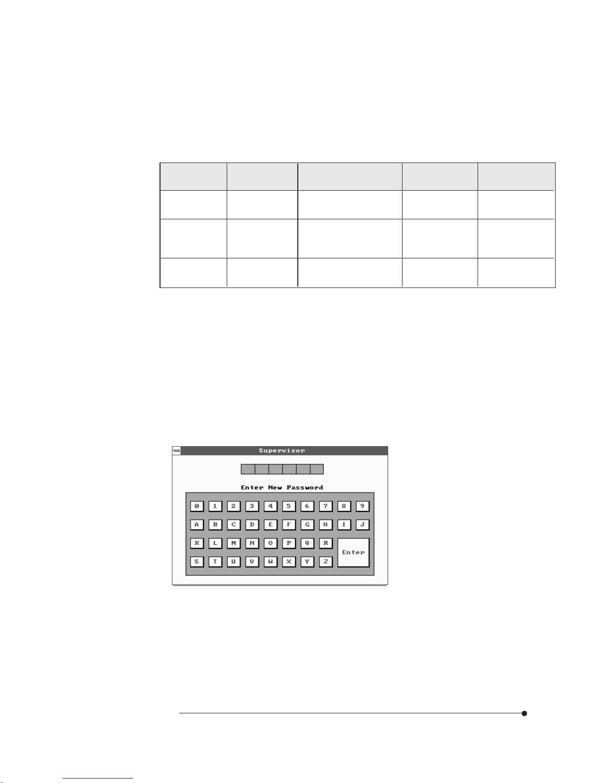
Setting a Password
Follow these steps to set your password:
When you see "Enter New Password" in the Supervisor or User window, type
the letter you want to use using the keyboard or click it using the mouse. You
can type up to six characters using the keys listed in the window. The screen
displays an asterisk for each character you type. After typing the password,
press Enter.
1
The system can be configured so that all users can enter a password every time
you turn on or reset the system, or run the Setup program, using Supervisor
password only or both passwords.
Page 37

2-20
Using the Setup Program
Deleting or Changing a Password
If you want to delete the current password, display the Supervisor or User
window and then follow these steps:
Select the Supervisor or User icon from the Security menu.
When you see "Enter Current Password", type the current password and press
Enter. If you select the User icon, the message does not appear.
When you see "Enter New Password", just press Enter to delete your current
password.
When you see "Confirm New Password", press Enter again.
When you exit the SETUP program, save your new settings. When you turn
on or reset your computer or run SETUP (depending on the setting in
Password Check of the Advanced Setup menu), you will see the password
prompt.
3
NoteNote
NoteNote
Note
Be sure to remember the password you enter or write it down. If you cannot
remember it, you will not be able to access the computer the next time you turn
it on or run SETUP. However, if you forgot your password, there is a way to
use your system again. See "Accessing Your Current Password" for more
information.
1
2
3
4
When you see "Confirm New Password", type your password again and press
Enter. If the password you type is different from your password, the screen
displays the message "Enter New Password". As you see the following
message, press Enter.
Supervisor Password Installed
or
User Password Installed
2
Page 38

2-21
Using the Setup Program
Disabling a Forgotten Password
If you forget your current password and cannot use your computer or run the
Setup, follow these steps:
Turn off the computer and disable the password function by setting the DIP
switch 3 to Off.
Turn on the computer. You will not see the prompt that asks you to enter your
password when you turn on the computer or run the Setup program.
If you want to set a new password, turn off the computer and enable the
password function by setting the DIP switch 3 to On.
Turn on the computer. As soon as the "Hit Del if you want to run SETUP"
message appears on the screen, press the Del key.
If you set a new password, the prompt that asks you to enter the password will
appear on the screen when you turn on or reset the computer or run the Setup
program.
If you did not set a new password, you would immediately use your system.
If you attempt to set a new password after you set the DIP switch 3 to Off to
disable your password, the password will not be saved to CMOS RAM.
1
2
3
4
When you see the following message, press Enter.
Both Passwords Uninstalled
or
User Password Uninstalled
To change the current password, type your new password before pressing Enter
on steps 3 and 4.
5
Page 39

2-22
Using the Setup Program
Anti-Virus
This option allows the user to protect the hard disk driver or diskette's boot
sector from unnecessary writing. The available settings are Enabled and Disabled.
Setting this option to Disabled makes writing on the boot sector possible.
If you select Enabled for this option, when you use the FORMAT, DISKCOPY, or
SYS command or any program that tries to write on the boot sector, you will see
the following warning message.
Boot Sector Write!!!
Possible VIRUS: Continue (Y/N)? _
At this point if you want to complete the running of the program regardless of the
message above, press Y.
If you see the message above in spite of having not run programs described
above, viruses may try to write on the boot sector. Select N to prevent the virus
from writing on the boot sector.
Notice that if you want to install MS-DOS, Windows 95, Windows NT, or OS/2,
set this option to Disabled.
Default MenuDefault Menu
Default MenuDefault Menu
Default Menu
The icons in this section permit you to select a group of settings for all Setup
options. Not only can you use these icons to quickly set system configuration
parameters, you can choose a group of settings that have a better chance of
working when the system is having configuration-related problems.
Page 40

2-23
Using the Setup Program
Original
Choose the Original icon to return to the system configuration values present in
Setup when you first began this Setup session.
Optimal
You can load the optimal default settings for the Setup by selecting the Optimal
icon. The Optimal default settings are best-case values that should optimize
system performance. If NVRAM is corrupted, the Optimal settings are loaded
automatically.
Page 41

3-1
Installing and Removing Board Options
Installing and Removing Board Options
Installing and Removing Board Options
Chapter 3
This Chapter describes how to install and remove optional board options in your
computer. You can use these instructions to install and remove a variety of
devices and board options. Although your board options may look a bit different
from the ones illustrated herein, you can install and remove it the same way.
Before YBefore Y
Before YBefore Y
Before Y
ou Beginou Begin
ou Beginou Begin
ou Begin
WW
WW
W
arningarning
arningarning
arning
The procedures in this chapter assume familiarity with the general terminology
associated with personal computers and with the safety practices and
regulatory compliance required for using and modifying electronic equipment.
Disconnect the computer from its power source and from any
telecommunications links, networks, or modems before performing any of the
procedures described in this chapter. Failure to disconnect power,
telecommunications links, networks, or modems before you open the computer
or perform any procedures can result in personal injury or equipment damage.
Some circuitry on the mother-board can continue to operate even though the
front panel power button is off.
CautionCaution
CautionCaution
Caution
Electrostatic discharge (ESD) can damage components. Perform the
procedures described in this chapter only at an ESD workstation. If such a
station is not available, you can provide some ESD protection by wearing an
antistatic wrist strap and attaching it to a metal part of the computer chassis.
Page 42

3-2
Installing and Removing Board Options
Installing the Microprocessor
Follow these steps to install the microprocessor:
Installing and Removing the MicroprocessorInstalling and Removing the Microprocessor
Installing and Removing the MicroprocessorInstalling and Removing the Microprocessor
Installing and Removing the Microprocessor
The ZIF (Zero Insertion Force) socket in your system enables you to replace
your CPU in its socket with other CPU.
You can install a microprocessor in a ZIF socket in your system to enhance the
performance and speed of your system. However, if the socket contains a
microprocessor, you must remove it before installing the new microprocessor.
NoteNote
NoteNote
Note
The processor can be different from illustrations described herein. There are
two types, passive heat-sink type (described herein) and active heat-sink fan
type, of the processor, but no functional difference.
Figure 12. Opening the ZIF socket
Lift up the socket handle up to open the ZIF socket. If there is a
microprocessor on the motherboard, you must remove it from its socket.
1
Page 43

3-3
Installing and Removing Board Options
Position the microprocessor over the socket, as shown below, so the notched
corner on the microprocessor marked with a dot is aligned with the notched
corner on the socket.
2
Figure 14. Inserting the microprocessor in the ZIF socket
Gently push the microprocessor into the socket, and press it until its pins are
inserted into the holes of the socket. Then press the ZIF handle downward to
close the ZIF socket.
3
Figure 13. Aligning the microprocessor on the ZIF socket
Page 44
3-4
Installing and Removing Board Options
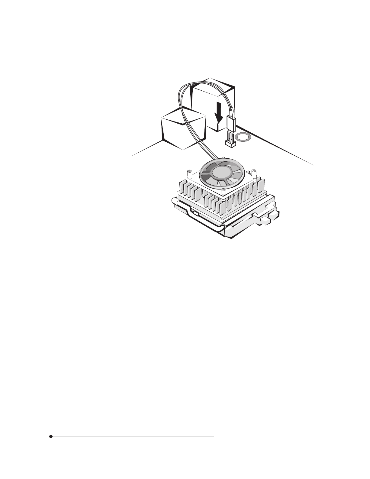
If there is a heatsink fan and its cable on the microprocessor, insert the fan
cable connector to the fan connector located on the motherboard.
4
Figure 15. Connecting the heatsink fan connector
Page 45

3-5
Installing and Removing Board Options
Setting the Processor Speed
After you install the processor on the motherboard, set the processor speed by
changing the settings of the DIP switches and jumper.
Refer to "Changing the DIP Switch and Jumper Settings" in this Chapter
Removing the Microprocessor
If there is a heatsink fan on the microprocessor and its cable connector is
inserted on the motherboard, pull out the connector from the motherboard.
1
Figure 16. Removing the heatsink fan connector
Page 46

3-6
Installing and Removing Board Options
Lift up the socket handle up to open the ZIF socket and remove a
microprocessor from its socket.
2
Press the ZIF handle downward to close the ZIF socket.
3
Figure 17. Removing the microprocessor from the ZIF socket
Page 47

3-7
Installing and Removing Board Options
Installing and RInstalling and R
Installing and RInstalling and R
Installing and R
emoving Memoremoving Memor
emoving Memoremoving Memor
emoving Memor
y Modulesy Modules
y Modulesy Modules
y Modules
The motherboard has three dual inline memory module (DIMM) sockets.
Minimum memory size is 8 MB; maximum memory size is 384 MB.
The BIOS automatically detects memory type, size, and speed.
Each DIMM socket supports the following memory features:
168-pin 3.3 V unbuffered DIMMs with gold-plated contacts
EDO DRAM
Non-ECC (64-bit) and ECC (72-bit) memory
Single or double sided DIMMs in the following sizes:
8MB, 16MB, 32MB, 64MB, and 128MB.
Memory can be installed in one, two, or three sockets. Memory size and speed
can vary between sockets.
NoteNote
NoteNote
Note
To purchase a DIMM, contact your dealer or an authorized service center for
assistance.
Page 48

3-8
Installing and Removing Board Options
Removing a Memory Module
To remove memory modules, press down the retaining tabs that secure the
DIMM at each end, using your fingers. Then carefully remove DIMM from the
socket.
Installing a Memory Module
Follow these steps to install DIMMs:
Make sure the clips at either end of the socket are pushed away from the
socket.
1
Position it by aligning the notches in the DIMM's edge connector with the
crossbars in the socket. Insert the bottom edge of the DIMM into the socket.
2
Press the DIMM straight down until retaining tabs snap into place around the
ends of the DIMM.
3
Figure 18. Installing a memory module
Figure 19. Removing a memory module
Securing clips
Page 49

3-9
Installing and Removing Board Options
Changing DIP Switch and Jumper SettingsChanging DIP Switch and Jumper Settings
Changing DIP Switch and Jumper SettingsChanging DIP Switch and Jumper Settings
Changing DIP Switch and Jumper Settings
A DIP (Dual Inline Package) switch is a small switch and a jumper is a small
electrical connector that controls one of the functions of your computer. The
settings of DIP switches and jumpers in your computer are preset at the factory;
however, you can alter the functions by changing the standard settings:
Specify CPU clock speed
Enable or disable the password function
Clear the CMOS settings
Select the motherboard type, etc.
Locations of the DIP Switches and Jumpers
Figure 20. DIP switches and jumpers
DIP switches
Aging jumper (J12)
CPU I/O VCC
setting jumper
(J11)
Motherboard type selection
jumpers (J8 and J10)
Main clock frequency jumper (J6)
CMOS clear
jumper (J3)
OFF ON
1
2
3
4
5
6
7
8
Page 50

3-10
Installing and Removing Board Options
1-2 ON ON O FF OFF 2.2V AMD K6
1-2 OFF O FF OFF ON 2.8V Intel P55C
1-2 ON OFF OFF O N 2.9V AMD K6, Cyrix 6x86MX
1-2 OFF O FF O N O N 3.2V AMD K6
2-3 OFF O N ON ON 3.4V Other non-MMX CPU*
Bus frequency
P54C P54CS P55C 6x86/6x86MX K5/K6
OFF ON ON - 150MHz 150MHz PR166MHz 150MHz
166MHz 166MHz PR200MHz 166MHz
OFF ON OFF - 200MHz 200MHz PR233MHz 200MHz
OFF OFF ON 120MHz 120MHz 120MHz PR133MHz 120MHz
133MHz 133MHz 133MHz 133MHz
OFF OFF OFF 90MHz 120MHz 233MHz PR266MHz 233MHz
100MHz 133MHz
ON ON ON - - - - 300MHz
ON ON OFF - - - - 300MHz
ON OFF ON - - - - 266MHz
ON O FF OFF - - - - Reserved
DIP Switch and Jumper Settings
DIP switches 5 through 7 allow you to adjust CPU clock speed in according to
the type of your system. The following table lists their settings.
Switch 7 Switch 6 Switch 5
Intel
The following table lists the settings of DIP switches 1 through 4 and a jumper
(J11).
J11 Switch 1 Switch 2 Switch 3 Switch 4 Output CPU type
* Other non-MMX CPU : Intel P54C(S), AMD K5, and Cyrix 6x86
NoteNote
NoteNote
Note
To set a DIP switch, push the DIP switch to the OFF or ON position.
CautionCaution
CautionCaution
Caution
Do not move the DIP switches or jumpers with the power on. Always turn off
the power and unplug the power cord from the computer before changing the
DIP switches and jumpers.
Page 51

3-11
Installing and Removing Board Options
2-3 2-3 Without sound system and hardware monitoring function
2-3 1-2 Without sound system, but with hardware monitoring function
1-2 2-3 With sound system and hardware monitoring function
1-2 1-2 Reserved
J8 J10 Motherboard type
The following table lists the settings of the motherboard type.
J6 1-2 66.8 MHz (CPU), 33.4 MHz (PCI)
(set the clock) 2-3 60.0 MHz (CPU), 30.0 MHz (PCI)
J12 1-2 Normal
(aging) 2-3 Final aging (Manufacturing setting)
Switch8 O N Disabled the password
(Password) OFF Enabled the Password
Setting Function
The following table lists the DIP switch and jumper settings for others.
The Things to do in PThe Things to do in P
The Things to do in PThe Things to do in P
The Things to do in P
ost-installationost-installation
ost-installationost-installation
ost-installation
After you install or remove board options, if neccessary, be sure to run Setup
program to update the configuration of you system. See Chapter 2 for detail
information.
If you installed a new optional equipment and Windows 95 has installed in your
system, you need to have Windows 95 detects it. See Windows 95 manual and
the manual that came with your optional equipment for detail information.
Page 52

4-1
Audio Drivers and Applications
Audio Drivers and Applications
Audio Drivers and Applications
Chapter 4
Installing the Audio DriversInstalling the Audio Drivers
Installing the Audio DriversInstalling the Audio Drivers
Installing the Audio Drivers
Follow these steps to reinstall the audio drivers for Windows 95:
The Crystal 4236B audio controller is built in the motherboard. If your system
comes with a hard disk drive installed, the audio drivers and applications will be
already installed in your system. However, if you need to reinstall them, install
them using the Driver CD that comes with your system as described in this
chapter.
Start the Windows 95 operating system.
1
Insert the driver CD into the CD-ROM drive.
2
From the Start menu, select Run. Click Browse, select
D:\audio\win95\English\Setup.exe, click Open, and click OK.
3
Page 53

4-2
Audio Drivers and Applications
NoteNote
NoteNote
Note
The Setup will do an automatic cleaning up of the Windows 95 Crystal Audio
registry entries. Many problems with reinstallation occur because of existing
registry entries from previous installations and because of the
"\WINDOWS\INF\OEMx.INF" files. After running setup, the various Crystal
devices from the Control Panel should disappear. It is recommended that prior
to running Setup, remove the device entries in the Sound, Video, and Game
Controller of the System Device Manager, and Crystal entries (if any) in the
Other detected devices section of the Device Manager.
At the Crystal Semiconductor dialog box, click Install Driver.
4
When the Complete Installation dialog box appears, click Restart.
5
Page 54

4-3
Audio Drivers and Applications
Windows 95 is restarted.
6
Windows 95 automatically recognizes new PnP audio hardware, creates a
database for the hardware, and proceeds with the installation of Crystal device
drivers.
7
If the Update Device Driver Wizard window appears, click Next.
8
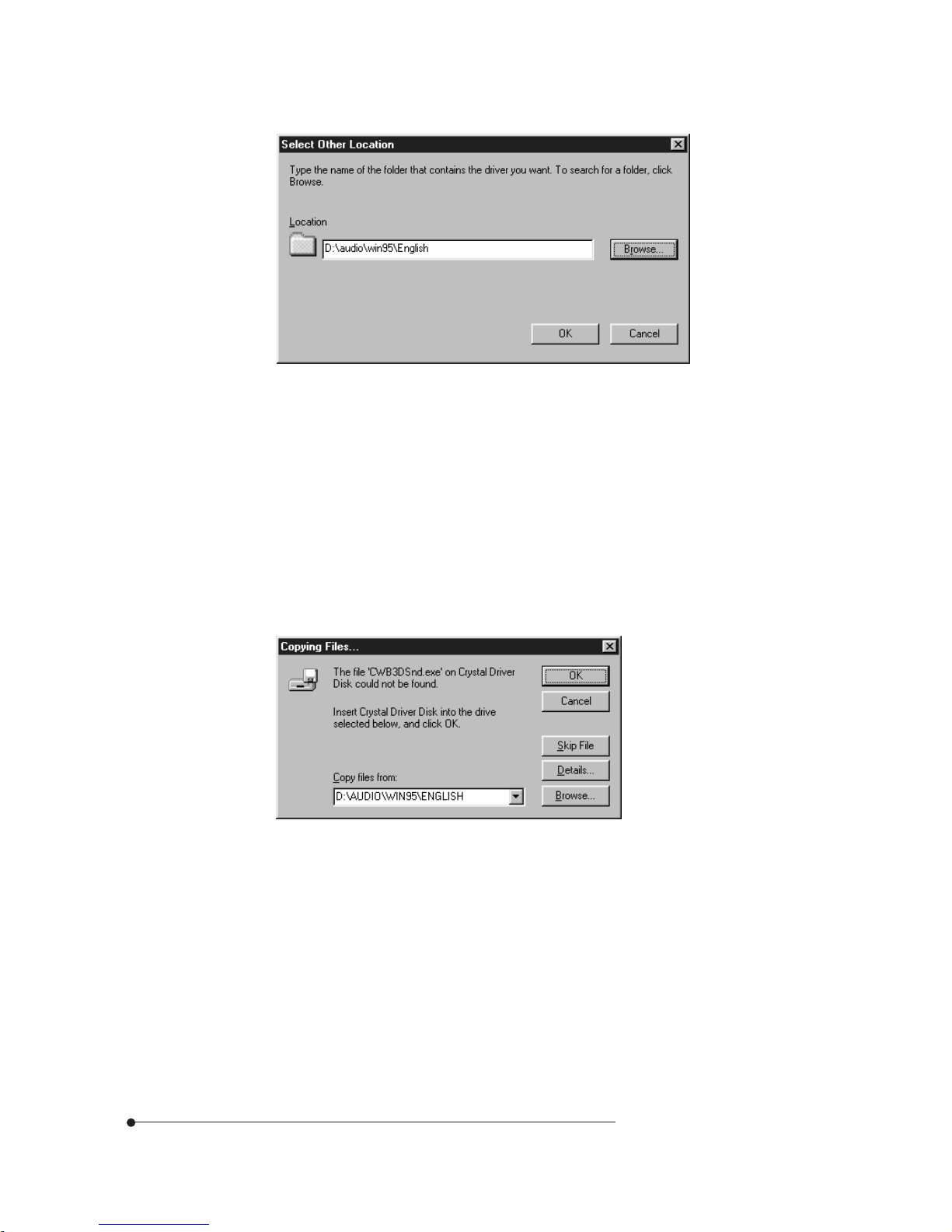
Click Other Locations. When the Select Other Location dialog box appears,
click Browse, select D:\audio\win95\English, and click OK.
9
Page 55
4-4
Audio Drivers and Applications
When the Select Other Location dialog box appears again, click OK and then
click Finish in the Update Device Driver Wizard window.
10
When the Insert Disk dialog box appears, click OK.
11
If the Copying Files dialog box appears prompting for the location of additional
files, click Browse, select D:\AUDIO\WIN95\ENGLSIH\CWB3DSND.EXE,
and click OK.
12
Click OK in the Copying Files dialog box.
13
Page 56

4-5
Audio Drivers and Applications
When the Insert Disk dialog box appears prompting for inserting the Windows
95 CD-ROM, remove the Driver CD, insert the Windows 95 CD, and click
OK.
14
When the Insert Disk dialog box appears prompting for inserting the Crystal
Driver Disk, remove the Windows 95 CD, insert the Driver CD into the
CD-ROM drive, and click OK.
15
When the New Hardware Found dialog box appears and D:\ AUDIO\WIN95\
ENGLISH is selected, click OK.
16
Page 57

4-6
Audio Drivers and Applications
If you select Settings | Control Panel from the Start menu and select System icon,
the System Properties window will appear. If you select the Device Manager tab
at this window after installing the audio drivers, you will see an additional line for
the audio drivers, "Sound, video and game controllers" in the Device Manager
window. Double clicking on the "Sound, video and game controllers" entry in the
Device Manager window, will expand the line to list the Crystal codec Logical
Devices installed as shown below.
Installing and Using the Audio ApplicationsInstalling and Using the Audio Applications
Installing and Using the Audio ApplicationsInstalling and Using the Audio Applications
Installing and Using the Audio Applications
Installing the Audio Applications
Follow these steps to install the audio utilities:
Insert the Driver CD into the CD-ROM drive.
1
Page 58

4-7
Audio Drivers and Applications
From the Start menu, select Run. Click Browse, select D:\audio\Voyetra\
Setup.exe, click Open, and click OK.
2
When the Software License Agreement window appears, click Yes.
3
When the Welcome dialog box is displayed, click Continue.
4
Page 59

4-8
Audio Drivers and Applications
Accept the folder displayed on the window or change folder. Then click
Install.
5
When Restart Windows appears, click Restart Windows for the changes to
take effect.
6
After you restart your operating system, the Voyetra program group would be
displayed on the screen and under Programs from the Start menu.
7
Page 60

4-9
Audio Drivers and Applications
AudioStation
AudioStation is a component audio system that can play or record audio CDs,
digital audio files (WAV or VOC), or MIDI files (MID, RMI or ORC). This
consists of Audio Mixer, CD Player, Digital Audio Player, and MIDI Player.
Audio Mixer lets you adjust the volumes of the various audio components and set
recording levels for digital audio. You can play audio CDs with the CD Player.
You can play digital audio (WAV) files with the Digital Audio Player and edit digital
audio files using WinDAT displayed by pressing the Edit button. With the MIDI
Player, you can play MIDI files. You can audition CD, WAV and MIDI files and
create custom playlists.
Using the Audio Applications
To use the audio applications (AudioStation and WinDAT), follow the next steps:
Start Windows 95.
1
Click the Start button, point to Programs, point to Yamaha, and then select
AudioStation or WinDAT.
2
Page 61

4-10
Audio Drivers and Applications
See the online help by clicking the button for information on using
AudioStation.
Page 62

4-11
Audio Drivers and Applications
WinDAT
WinDAT is a digital audio editor that can playback, record, or edit digital audio
files (WAV or VOC). This can be selected from the Start menu or be launched
from the Digital Audio Player of AudioStation.
See the online help by pressing F1 for information on using WinDAT.
Page 63

5-1
Update on Installing Windows 95
Update on Installing Windows 95
Chapter 5
Installing the USB driver
Installing the ACPI driver
1
Update on Installing Windows 95
If you reinstalled or upgraded Windows 95, you need to install the drivers. Follow
the next steps:
2
Installing the AGP VxD driver (if you installed the AGP driver)
5
Installing the Audio drivers (manufacturing option, see chapter 4 Audio
Drivers and Applications)
6
Installing the AGP driver (optional, if you installed the AGP card in your
system : for more information, refer to the manual that comes with your
optional AGP card)
3
Installing the DirectX-5 driver (if you installed the AGP driver)
4
Page 64

5-2
Update on Installing Windows 95
Installing the USB DriverInstalling the USB Driver
Installing the USB DriverInstalling the USB Driver
Installing the USB Driver
Your motherboard has two USB ports. USB is the next generation of peripheral
interface design. USB allows easy attachment of peripherals to your system.
NoteNote
NoteNote
Note
To install from your Windows 95 CD, be sure your Windows95 CD is OSR2
with USB support version. (See on the surface of Windows 95 CD title.)
Follow these steps for USB driver installation.
Insert Windows 95 CD-ROM into CD-ROM drive.
1
Click the Start button, and then click Run.
2
Set the path to "D:\other\usb\usbsupp.exe" and click OK to install the
Microsoft USB Supplement to your system.
3
Click Yes, and then click Yes to accept the agreement.
4
Setup will scan your system. Click OK to complete setup when the installation
is finished. Setup will restart your system.
5
The USB driver is included in your Windows 95 CD.
NoteNote
NoteNote
Note
It is recommended that prior to running Usbsupp to install the USB driver,
remove the PCI Universal Serial Bus entries (if any) in the Other Devices of
the Device Manager from the Control Panel.
Page 65

5-3
Update on Installing Windows 95
Installing the ACPI DriverInstalling the ACPI Driver
Installing the ACPI DriverInstalling the ACPI Driver
Installing the ACPI Driver
The Advanced Configuration and Power Interface (ACPI) specification provides
a key element in Operating System Directed Power Management (OSPM). OSPM
and ACPI both apply to all classes of computers.
ACPI evolves the existing collection of power management BIOS code, APM
APIs, PNPBIOS APIs, and so on into a well-specified power management and
configuration mechanism.
Follow these steps to install the ACPI driver:
Click the Start button, and then click Run.
1
Insert the Driver CD into your CD-ROM drive.
2
Click Browse, select D:\VIA\ACPI Driver\Setup.exe, click Open, and click
OK.
3
If an "Update Device Driver Wizard" window appears after Windows 95
reboots, follow the instructions on screen. Proceed to step 7, otherwise USB
installation is finished.
6
Click Next to continue.
7
Click the Finish button.
8
Set the path to "C:\windows\system" and click OK.
9
Page 66

5-4
Update on Installing Windows 95
When the VIA Power Management Controller window is displayed, click
Next.
4
Select Install VIA ACPI Patch and click the Next button.
5
Page 67

5-5
Update on Installing Windows 95
Select "Yes, I want to restart my computer now." and click the Finish button
to restart the computer.
6
Installing the DirectXInstalling the DirectX
Installing the DirectXInstalling the DirectX
Installing the DirectX
-5 Driver-5 Driver
-5 Driver-5 Driver
-5 Driver
To use the AGP driver, install the DirectX-5 driver.
Follow these steps to install the DirectX-5 driver:
Click the Start button, and then click Run.
1
Insert the Driver CD into your CD-ROM drive.
2
Click Browse, select D:\DX-5\Setup.exe, click Open, and click OK.
3
Page 68

5-6
Update on Installing Windows 95
Installing the AGP VxD DriverInstalling the AGP VxD Driver
Installing the AGP VxD DriverInstalling the AGP VxD Driver
Installing the AGP VxD Driver
Follow these steps to install the AGP VxD driver:
Click the Start button, and then click Run.
1
Insert the Driver CD into your CD-ROM drive.
2
Click Browse, select D:\VIA\AGP VxD for WIN95\Setup.exe, click Open,
and click OK.
3
The DirectX-5 driver will be installed in your hard disk drive.
4
Page 69

5-7
Update on Installing Windows 95
When the VIAGART Setup Program window is displayed, click Next.
4
Select Install VIA AGP VxD and click the Next button.
5
Page 70

5-8
Update on Installing Windows 95
Select "Yes, I want to restart my computer now." and click the Finish button
to restart the computer.
6
Page 71

A-1
Specifications
FF
FF
F
orm Form F
orm Form F
orm F
actoractor
actoractor
actor
ATX form factor of 12 * 7.75 inches
ProcessorProcessor
ProcessorProcessor
Processor
Intel Pentium up to 200 MHz processor
Intel Pentium up to 233 MHz processor with MMX technology
AMD K5/K6 up to 233 MHz processor (Ready for up to 300MHz)
Cyrix 6x86 or 6x86MX/PR 200MHz processor
Main MemorMain Memor
Main MemorMain Memor
Main Memor
yy
yy
y
Three 168-pin DIMM sockets
Supports up to 384 MB of synchronous DRAM (SDRAM) memory
Supports EDO DRAM
ECC or non-ECC memory
Specifications
Specifications
Appendix A
Page 72

A-2
Specifications
Apollo VP3 AApollo VP3 A
Apollo VP3 AApollo VP3 A
Apollo VP3 A
GPset and PCI/IDE InterGPset and PCI/IDE Inter
GPset and PCI/IDE InterGPset and PCI/IDE Inter
GPset and PCI/IDE Inter
faceface
faceface
face
VT82C597 single chip north bridge (PCI/AGP/Memory controller (PAC))
- Integrated PCI bus mastering controller
- Integrated Accelerated Graphics Port (AGP) controller
- Integrated memory controller
VT82C586B PCI/ISA/IDE Xcelerator
- Supports up to four IDE drives or devices
- PC-97 compatible PCI-to-ISA bridge
- USB and DMA controllers
- Keyboard and mouse controller
- Two fast IDE interfaces
- Power management logic
- Real-time clock controller
I/O featuresI/O features
I/O featuresI/O features
I/O features
IT8661F Super I/O controller
- Integrates standard I/O functions: floppy-drive interface, one multimode
parallel port, two FIFO serial ports, IrDA-compatible interface
Two Universal Serial Bus (USB) interfaces
Page 73

A-3
Specifications
Six usable expansion slotsSix usable expansion slots
Six usable expansion slotsSix usable expansion slots
Six usable expansion slots
One ISA slot
Three PCI slots
One shared PCI/ISA slot
Onboard AGP connector
Other featuresOther features
Other featuresOther features
Other features
AMI BIOS
Plug and Play compatible
Advanced Power Management (APM, ACPI)
Manufacturing OptionsManufacturing Options
Manufacturing OptionsManufacturing Options
Manufacturing Options
Management extension hardware (Sound system and hardware monitoring
function)
PP
PP
P
ower Supplyower Supply
ower Supplyower Supply
ower Supply
For typical configurations, the motherboard is designed to operate with at least a
200 W power supply. A higher-wattage power supply should be used for heavilyloaded configurations. The power supply must meet the following requirements:
Rise time for power supply: 2 ms to 20 ms
Minimum delay for reset to Power Good: 100 ms
Minimum Powerdown warning: 1 ms
3.3 V output must reach its minimum regulation level within (20 ms of the +5
V output reaching its minimum regulation level)
Page 74

B-1
Error and Information Messages
Timer Error The timer test failed. Requires repair of system motherboard.
CMOS battery Low CMOS RAM is powered by a battery. The battery power is
low. Replace the battery.
CMOS Checksum Bad After CMOS RAM values are saved, a checksum value is
generated for error checking. The previous value is different
from the current value. Run BIOS Setup.
CMOS Settings Wrong The values stored in CMOS RAM are either corrupt or
nonexistent. Run BIOS Setup.
CMOS Display Type Wrong The video type in CMOS RAM does not match the type
detected by the BIOS. Run Setup.
Unlock Keyboard The keyboard lock on the computer is engaged. The computer
must be unlocked to continue.
Keyboard Error Keyboard not working.
KB/Interface Error There is an error in the keyboard connector.
CMOS Memory Size Wrong The amount of memory on the motherboard is different than
the amount in CMOS RAM. Run BIOS Setup.
FDC Failure The BIOS cannot communicate with the floppy disk drive
controller. Check all appropriate connections after the com
puter is powered down.
Pri Master(Slave) HDD Error Primary Master (Slave) HDD is not working or nor configured
properly. Check to see if fixed disk is installed properly.
Error and Information Messages
Error and Information Messages
Appendix B
BIOS Error MessagesBIOS Error Messages
BIOS Error MessagesBIOS Error Messages
BIOS Error Messages
Error Message Explanation
Page 75

B-2
Error and Information Messages
Sec Master(Slave) Secondary Master (Slave) HDD is not working or nor config
HDD Error ured properly. Check to see if fixed disk is installed properly.
CMOS Date/Time Not Set Run Standard Setup to set the date and time in CMOS RAM.
A: Drive Error or Drive A or B is present but fails the POST diskette tests.
B: Drive error Check that the drive is defined with the proper diskette type
in Setup and that the diskette drive is installed correctly.
Cache Memory Error Cache memory is defective.
GA20 Error Gate A20 on the keyboard controller is not working.
DMA Error Error in the DMA controller.
Error Message Explanation
BIOS Beep CodesBIOS Beep Codes
BIOS Beep CodesBIOS Beep Codes
BIOS Beep Codes
Beeps codes represent a terminal error. If the BIOS detects a terminal error
condition, it outputs an error beep code, halts the POST, and attempts to display a
port 80h code on the POST card's LED display.
Beeps 80h Code
Description
1
B4h One short beep before boot
1-2 98h Search for option ROMs
1-2-2-3
16h BIOS ROM checksum
1-3-1-1 20h Test DRAM refresh
1-3-1-3
22h
Test 8742 keyboard controller
1-3-4-1 2Ch RAM failure on address line xxxx*
1-3-4-3 2Eh
RAM failure on data bits xxxx* of low byte of memory bus
1-4-1-1
30h
RAM failure on data bits xxxx* of high byte of memory bus
2-1-2-3 46h Check ROM copyright notice
2-2-3-1 58h Test for unexpected interrupts
Page 76

C-1
Motherboard Resources
0 8- or 16-bits Audio (if present, else user available)
1 8- or 16-bits Audio / parallel port (if present, else user available)
2 8- or 16-bits Floppy drive (if present, else user available)
3 8- or 16-bits Parallel port (for ECP)/audio
Motherboard Resources
Motherboard Resources
Appendix C
DMA ChannelsDMA Channels
DMA ChannelsDMA Channels
DMA Channels
DMA Channel Data Width System Resource
Number
(if present, else user available)
4 Reserved - cascade channel
5 16-bits Reserved
6 16-bits Reserved
7 16-bits Reserved
Page 77

C-2
Motherboard Resources
InterruptsInterrupts
InterruptsInterrupts
Interrupts
IRQ System Resource
NMI
I/O channel check
0
Interval timer
1 Keyboard
2
Cascade interrupt from slave PIC
3 COM2*
4
COM1*
5
LPT2 (Plug and Play option) / audio (if present, else user available)
6 Floppy drive
7
LPT1*
8 Real time clock
9
User available
10 User available
11 Windows Sound System* / USB (if present, else user available)
12
Onboard mouse port (if present, else user available)
13
Math coprocessor
14 Primary IDE (if present, else user available)
15 Secondary IDE (if present, else user available)
* Default, but can be changed to another IRQ
Page 78

Application of Council Directives 89/336/EEC EMC Directive
Manufacturer s Name TriGem Computer Inc.
Manufacturer s Address 1055 Shin-gil-Dong, Ansan City, Kyunggi
Do, Republic of Korea
European Representative Name TriGem Computer (U.K.) Ltd.
European Representative Address 69 Bucking Ave. Trading Estate Slough
Berkshire SL1 4PN U.K.
Equipment Type/Environment Main Board
Model Name LI545
Conformance to
European International
EN 55022 (1995 Class B) CISPR 22 (1985 Class B)
EN 50082-1 (1992) IEC 801-2 (1984 Level 3)
EN 61000-3-2 (1995) IEC 801-3 (1984 Level 2)
EN 61000-3-3 (1995) IEC 801-4 (1988 Level 2)
We hereby declare that the equipment specified conforms to the above Directives.
Manufacturer Legal Representative in Europe
Full Name Full Name
Sang-Ryong Ko Hyun Woo Choi
Position Position
Dept. Manager President
Place Place
1055 Shin-gil-Dong, Ansan City, 69 Bucking Ave. Trading Estate
Kyunggi Do, Republic of Korea Slough Berkshire SL1 4PN U.K.
Date Date
December, 1997 December, 1997
Declaration of Conformity (CE)Declaration of Conformity (CE)
Declaration of Conformity (CE)Declaration of Conformity (CE)
Declaration of Conformity (CE)
 Loading...