


Hardware Document
TGDFBD06-A Board Development Team
Dublin
Motherboard
Hardware Document
August. 03, 2001
Revision 0.9
TriGem Computer Inc. 1 / 16 Revision 0.9
Hardware Document
TGDFBD06-A Board Development Team
Document Revision History
Released date Revision Description
August 03, 2001
User’s Notice
No part of this product, including the schematics and BIOS may be reproduced, transmitted, transcribed,
stored in a retrieval system, or translated into any language in any form by any means without the
express written permission of TriGem Computer Inc. except the document kept by the purchaser
for backup purposes.
© Copyright 2001 TriGem Computer Inc. All rights reserved
Rev. 0.9 First prepared for this document.
This document describes the major specification of the Dublin
motherboard and the functional feature to be extended by the customer.
The motherboard revision number is EVT1.
TriGem Computer Inc. 2 / 16 Revision 0.9

Hardware Document
TGDFBD06-A Board Development Team
Contents of Table
I. Introduction
1. General Description ------------------------------------------------------------ ------------ 4
2. Functional Block Diagram ------------------------------------------------------------ 6
II. System Overview
1. Major Units ----------------------------------------------------------------------------- 7
2. Upgrade ability ------------------------------------------------------------------------- 8
2-1. Processor -------------------------------------------------------------------------- 8
2-2. Memory ----------------------------------------------------------------------------- 8
2-3. BIOS --------------------------------------------------------------------------------- 9
2-4. Expansion Slot -------------------------------------------------------------------- 9
2-5. Advanced Configuration and Power Interface (ACPI) ------------------- 10
2-6. Manufacturing Options ---------------------------------------------------------- 10
III. Jumpers & Connectors Descriptions
1. Motherboard Jumpers Settings ------------------------------------------------------ 11
1-1. Selection of Processor CPU Clock ---------------------------------------------- 11
1-2. Clock Setting (J6, J7, J8) ---------------------------------------------------------- 12
1-3. OEM/ODM selector (J1, J3) ------------------------------------------------------- 12
1-4. Configuration Selector (J9, J10, J11) ---------------------------------------------- 12
2. I/O Headers & Connectors Descriptions ------------------------------------------- 13
2-1.Motherboard Internal Connectors --------------------------------------------- 13
2-2.Motherboard External I/O Ports ------------------------------------------------ 16
TriGem Computer Inc. 3 / 16 Revision 0.9

Hardware Document
TGDFBD06-A Board Development Team
I. Introduction
The Dublin u-ATX motherboard offers a time-to-market consumer desktop solution featuring the Intel Pentium-4
processor in the 478 Pin package and the Northwood Processor with the 400MHz front side bus and Intel 845
Chipset. The Dublin motherboard was designed to have highly minimized system cost. Additional H/W platform
features include AGP 4x mode, PC133 System memory, Ultra ATA/100, Low Pin Count (LPC) interface, Universal
Serial Bus and PCI audio solution with AC97 CODEC make the expensive audio add-in cards unnecessary. The
platform is also ACPI compliant and support Full-on, Stop Grant, STR, STD, and Soft-off power management
states. After all, the Dublin motherboard is a good solution for the customers who want a PC with an affordable
price.
1. General description
q Motherboard
• PCB size in the u-ATX form factor
• 9.6” * 9.6” * 1.6t (4 Layers)
q Processors
Intel Pentium-4 Processor in the 478 Pin Package/Northwood Processor
• Intel Memory Controller Hub-MCH (North bridge)
• Intel I/O Controller Hub2-ICH2 (South Bridge)
- Intel 82801BA
• LPC I/O Controller : SMSC SMC47M112
• DC-DC Converter : Intersil HIP6301 + HIP6601A*2
• Clock Generator : ICS9250-38(CK408)
• EtherNet Controller : ADMTek AN983B
• System Memory
- Supports up to 3 double-sided DIMMs (6 device rows) with 64-bit data interface
- Supports up to 1.5GB using 256Mb technology and up to 3GB using 512Mb technology
- SDR-DRAM interface runs at 133MHz speed with 400MHz FSB
• Flash Memory : Programmable 4Mb Flash memory for BIOS
- Three PCI slots
- One multi-mode parallel port (LPT1)
- One FIFO serial port (COM1)
- PS/2 style Keyboard and Mouse ports
- Stacked two USB ports (USB0,1) & One RJ-45 Jack for LAN
• Other integrated extended I/O ports (by the Header type)
- 20 Pin Headers for Power Button/Sleep button/Power LED/HDD LED/Reset button/Key-Lock
- One FIFO serial port (COM2)
- One Speaker-Out port
- One CD-Audio-In port and One AUX-In(for 2nd CD-In) port
•
q Main Chipset
- Intel 82845
• Audio Subsystem : AC 97 Link for Audio and Telephony CODECs in ICH2 and
q Memory Subsystem
q
I/O Features
• Integrated standard Bus interface slots
- One AGP slot with 1.5V(Only 4x)
• Integrated standard I/O ports in the Rear side
- Three Audio jacks for Line-In, MIC-In, and Line-Out (or SPK-Out)
- One Joystick port
- Two USB ports (USB2,3)
- One S/PDIF port
- One Video Sound-In port
- One Headphone port and One MIC-In port
- One PC-PCI port
Crystal CS4201 CODEC
TriGem Computer Inc. 4 / 16 Revision 0.9

Hardware Document
TGDFBD06-A Board Development Team
q
- Supports Ultra DMA-100/66/33, BMIDE and PIO modes
- Separate IDE connections for Primary and Secondary cables
- Read transfers up to 100MB/s. Writes to 89MB/s
- Dual channel master mode PCI supporting four Enhanced IDE devices
• Built in PCI Audio Controller in Intel ICH2 and CS4201 CODEC
- AC’97 2.1 compliant
- Independent bus master logic for 5 channels (PCM In/Out, MIC Input, Modem In/Out)
- Support for up to six channels of PCM Audio output (full AC3 decode)
- Supports wake-up events
• Crystal CS4201 CODEC
- AC’97 2.1 compliant
- Stereo Headphone Amplifier
• Full-featured Accelerated Graphics Port (AGP) Controller
- Supports full AGP 2.0 capability for maximum bus utilization including 2x and 4x mode transfers
- AGP 1.5V connector support only
- IEEE802.3u 100BASE-TX and IEEE802.3 10BASE-T compliant
- Support for IEEE802.3x flow control
- IEEE802.3u Auto-Negotiation support for 10BASE-T and 100BASE-TX
- PCI Specification 2.2 compliant
- ACPI and PCI power management ver 1.1. Compliant
- Support PC9 wake-on LAN
- Provides 32-bit PCI bus master data transfer
- Supports network operation with PCI system clock from 20MHz to 33MHz
- Provides burst transmit packet interrupt and transmit/receive early interrupt to reduce host CPU
utilization
- Supports memory-read, memory-read-line, memory-read-multiple, memory-write,
memory-write-and-invalidate command while being bus master
- Supports big or little endian byte ordering
- Provides write-able EEPROM as boot ROM with size up to 128KB
- Re-writes Flash boot ROM through I/O port by programming register
- Provides serial interface for read/write 93C36 EEPROM
- Integrates the whole Physical layer function of 100BASE-TX and 10BASE-T
- Provides Full-duplex operation on boot 100Mbps and 10Mbps modes
- Provides Auto-negotiation (NWAY) function of full/half duplex operation for both 10 and 100Mbps
- Provides MAC and Transceiver (TXCVR) loop-back modes for diagnostic
- Builds in Stream Cipher Scrambler / De-scrambler and 4B/5B encoder/decoder
Integrated IDE Subsystem
- Independent timing of up to 4 drives
q
Audio Subsystem
- Supports the S/PDIF (IEC-958) optical digital out
q
Graphic Subsystem (AGP)
- High priority access support
q Ethernet Subsystem (LAN)
• Industry Standard
• PCI interface
• EEPROM/BOOT ROM interface
• MAC/Physical interface
TriGem Computer Inc. 5 / 16 Revision 0.9

Hardware Document
Pentium-4
Joystick and
CS4201
LAN
1
BIOS
FWH
TGDFBD06-A Board Development Team
2. Functional Block Diagram
(478 Pin Package)
Host Interface
3 SDRM DIMM Modules
Primary IDE
Secondary IDE
4 USB Ports
FDD
i82845i82845
Hub Interface
(ICH2)
LPC interface
SMCSMC
47M11247M112
(LPC I/O)
PCI Interface
AGP (Up to 4X) Slot
3 PCI Slots
AN983B
controller
CODEC
K/B
Parallel Port
MOUSE
2 Serial Ports
Speaker
Line In
MIC
MIDI
Rear Ports
TriGem Computer Inc. 6 / 16 Revision 0.9
Hardware Document
2
3
7
8
5
12
1
9
6
4
11
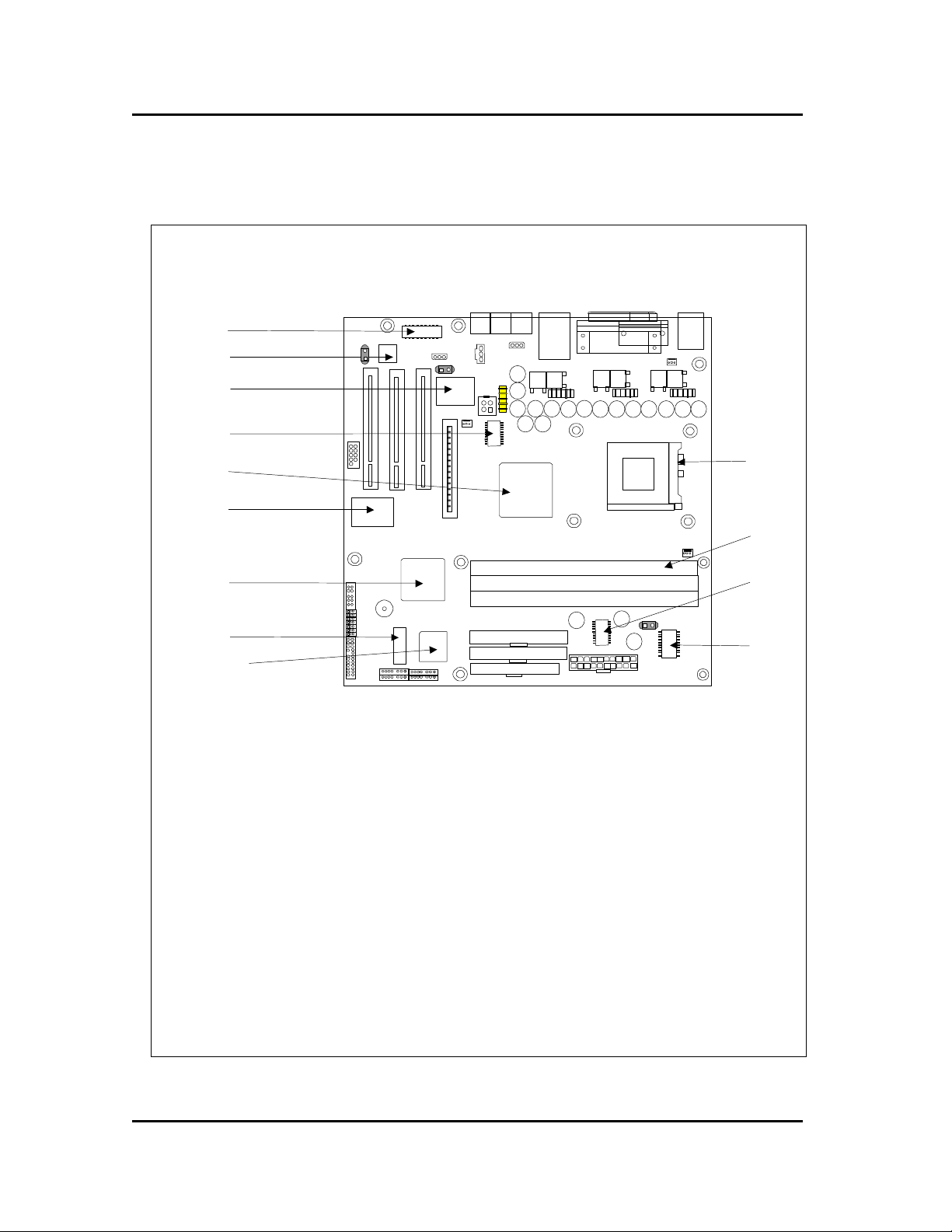
TGDFBD06-A Board Development Team
II. System Overview
1. Major Units
13
10
1. Audio Power AMP : TI TPA1517
2. AC97 CODEC : Crystal CS4201
3. PCI Ethernet controller : ADMTek AN983B
4. DC-DC Converter : HIP6301
5. North Bridge : Intel i82845(MCH)
6. LPC I/O Controller : SMSC SMC47M112
7. South bridge : Intel i82801BA(ICH2)
8. Battery : CR2032
9. Firmware Hub(BIOS) : Intel 82802AB(FWH)
10. Clock generator : ICS9250-38(CK408)
11. ACPI Power Controller : HIP6503
12. DIMM sockets : PC133 SDRAM
13. CPU Socket : Intel Pentium-4 478 Processor Socket
TriGem Computer Inc. 7 / 16 Revision 0.9

Hardware Document
TGDFBD06-A Board Development Team
2. Upgradeability
2-1. Processor
The Dublin motherboard provides the 478-pin FC-BGA socket, which supports Willamette & Northwood and
is not backward compatible with PGA socket-7 processors. The voltage regulator on the motherboard is
programmed to output the required voltage by the processor itself through the processor’s VID pin.
q Supported Intel 478 Pin Package Processors: Willamette and Northwood
2-2. Memory
The Dublin motherboard has three Dual Inline Memory Modules (DIMMs), minimum 32MB to maximum 3GB
memory size. The BIOS detects the memory type, size, and speed through SMBUS interface between the core
chipset and DIMM module automatically.
The motherboard supports the following memory features
• 3.3V and unbuffered 168-pin DIMM
Voltage detection
3.3V Version 5V Version
Unbuffered detection
Unbuffered Buffered
• DRAM interface synchronous with host CPU (400 MHz)
• Supports 64Mb, 128Mb, 256Mb and 512Mb technology for x8 and x16 devices
• All supported devices must have 4 banks
• Supports page sizes of 2KB, 4KB, 8KB and 16KB
• Supports up to 1.5GB using 256Mb technology and up to 3GB using 512Mb technology
• ECC DIMM support
•
133MHz(PC133) SDRAM interface
• No registered DIMM support
• Support for Symmetric and Asymmetrical DRAM addressing
• Refresh Mechanism: CAS-before-RAS only
•
Support for DIMM Serial Presence Detect (SPD) scheme via SMBus interface
• STR power management support via self refresh mod using CKE
TriGem Computer Inc. 8 / 16 Revision 0.9

Hardware Document
TGDFBD06-A Board Development Team
2-3 BIOS
q Flash memory (FWH) organization
The motherboard uses a Phoenix BIOS, which is stored in the flash memory (FWH) and can be upgraded using
a disk-based program. An old version of the BIOS can be updated to the newer version using the Flash
Memory Update utility in a floppy diskette.
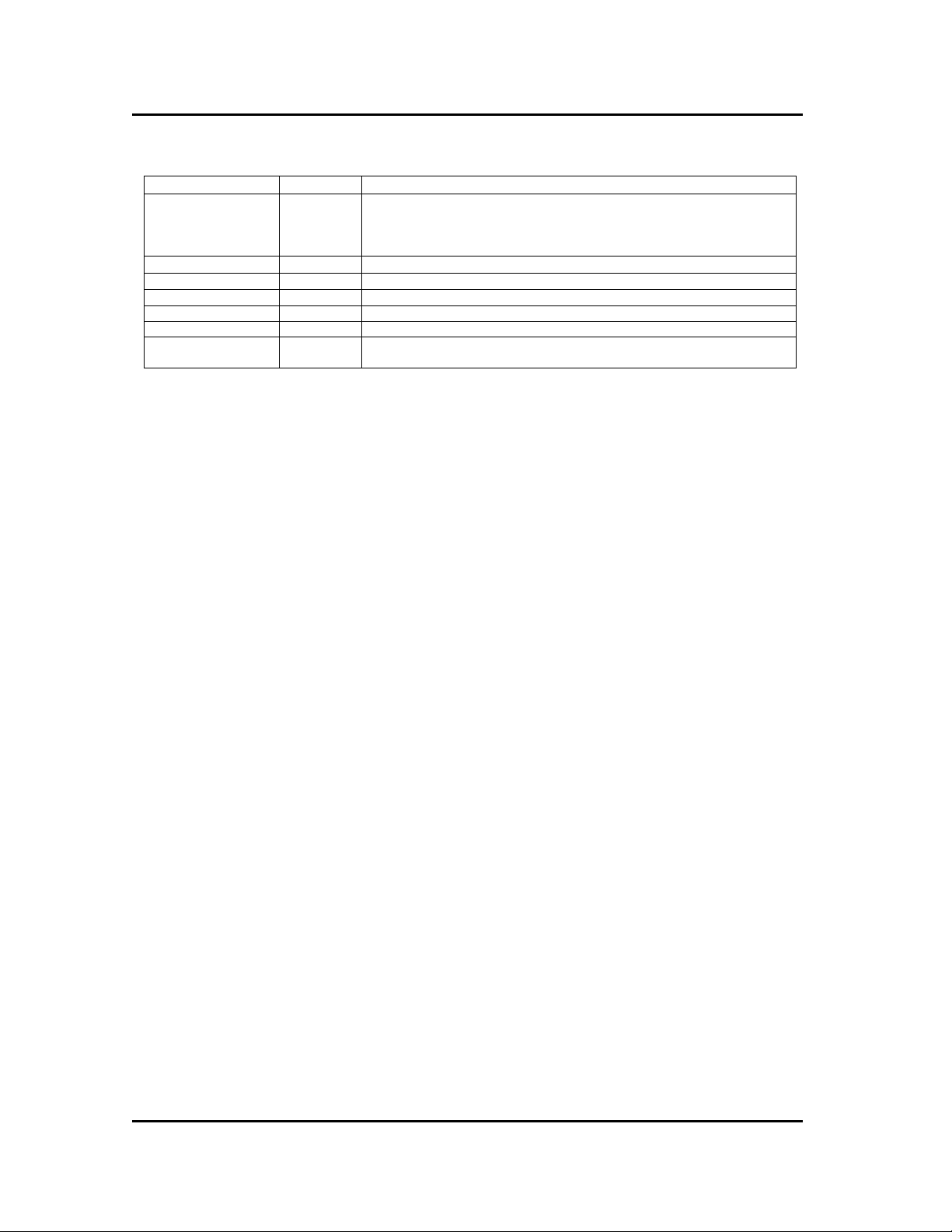
Address (Hex) Size Functional description
FFFFC000 – FFFFFFFF 16KB Main BIOS block#1
FFFFA000 – FFFFBFFF 8KB ESCD
FFFC0000 – FFF9FFFF 232KB Main BIOS block#2
q On-board device management
The BIOS enables or disables the devices on the motherboard with reference to the values of the contents in
CMOS setup menu. User can also disable the CMOS setup by setting the corresponding jumper (described in
III-1 Motherboard Jumper Setting section).
Device Description CMOS setup menu Default value
PS/2 Mouse SMSC SMC47M112 Enabled / Disabled / Auto Detect Auto Detect
On board serial A SMSC SMC47M112 Enabled/ Disabled Enabled
On board serial B SMSC SMC47M112 Enabled/ Disabled Enabled
On board parallel SMSC SMC47M112 Enabled/ Disabled Enabled
Audio Controller Intel 82801BA Enabled / Disabled Enabled
Midi Port SMSC SMC47M112 Enabled/ Disabled Enabled
Game Port SMSC SMC47M112 Enabled/ Disabled Enabled
On board LAN ADMTek AN983B Enabled/ Disabled Enabled
<Simplified flash memory address map>
<CMOS setup options for on-board devices>
2-4. Expansion Slot
q
On-board PCI devices information
The Dublin motherboard has integrated PCI devices and AGP graphics controller core, and three PCI slots for
the expansion purpose.
Bus number Device number Function number Device
00 00h 00 North Bridge (Intel 82845-MCH)
00 01h 00 AGP Controller ((Intel 82845-MCH)
00 07h 00 South bridge (Intel 82801BA-ICH2)
00 07h 01 IDE bus master (Intel 82801BA-ICH2)
00 07h 02 USB Controller 1(Intel 82801BA-ICH2)
00 07h 03 USB Controller 2(Intel 82801BA-ICH2)
00 07h 04 Power management (Intel 82801BA-ICH2)
00 07h 05 AC97 Controller (Intel 82801BA-ICH2)
01 00h 00 AGP Slot
02 09h 00 PCI slot1
02 0Ah 00 PCI slot2
02 0Bh 00 PCI slot3
02 02h 00 AN983B LAN Controller
<On-board PCI devices address map>
TriGem Computer Inc. 9 / 16 Revision 0.9

Hardware Document
TGDFBD06-A Board Development Team
q PCI interrupt & master number routing map
Intel I/O controller Hub-2 (ICH2) has eight programmable interrupt request input signals. Each of the PCI
interrupt source is connected to one of these interrupts signals and assigned to the free proper interrupt number
by PnP BIOS.
ICH2 INT
Signals
PIRQA
PIRQB INTA
PIRQC
PIRQD INTD
PIRQE INTD INTC INTB
PIRQF INTA INTD INTC
PIRQG INTB INTA INTD
PIRQH INTC INTB INTA INTC
Master REQ0 REQ1 REQ2 REQ3
IDSEL AD25 AD26 AD27 AD18
First
PCI slot
Second
PCI slot
Third
PCI slot
On Board
Ethernet
i82810BA
2-5. Advanced Configuration and Power Interface (ACPI)
The Dublin motherboard and system BIOS support the ACPI 1.0b that requires an ACPI-aware operating
system such as Windows-2000 or Windows-XP. ACPI feature include
•
System Sleeping State Control
- ACPI S1 state : Like C2 state(only STPCLK# active, and SLP# optional)
- ACPI S3 state : Suspend to RAM (STR)
- ACPI S4 state : Suspend to Disk (STD)
- ACPI S5 state : Soft Off (SOFF)
• Plug and play functionality normally contained in the BIOS
•
Indication LED for normal mode (Green) and suspend mode (Blinking Green) but this function is dependent
on the LED logic or BIOS control
• Supports multiple wakeup events
q Wakeup devices and operations
Wakeup devices Wakeup operations
Power switch Wakeup from Suspend mode (S1, S3 and S4) and Soft Off (S5)
USB device Wakeup from Suspend mode (S1 and S3)
PS/2 Mouse and K/B Wakeup from Suspend mode (S1 and S3)
PCI device (PME#) Wakeup from Suspend mode (S1 and S3)
LAN Wakeup from Suspend mode (S1 and S3)
2-6. Manufacturing Options
The motherboard has several manufacturing options according to OEM/ODM requirement. Make sure that
these options can be applied in the assembly stage, and it’s impossible to upgrade or change in the customer
field.
Option items Number of Ports
Joystick port 1EA
USB port 4EA
2nd CD-In(AUX-In) 1EA
S/PDIF 1EA
TV-Audio-In 1EA
TriGem Computer Inc. 10 / 16 Revision 0.9
Hardware Document
J4
TGDFBD06-A Board Development Team
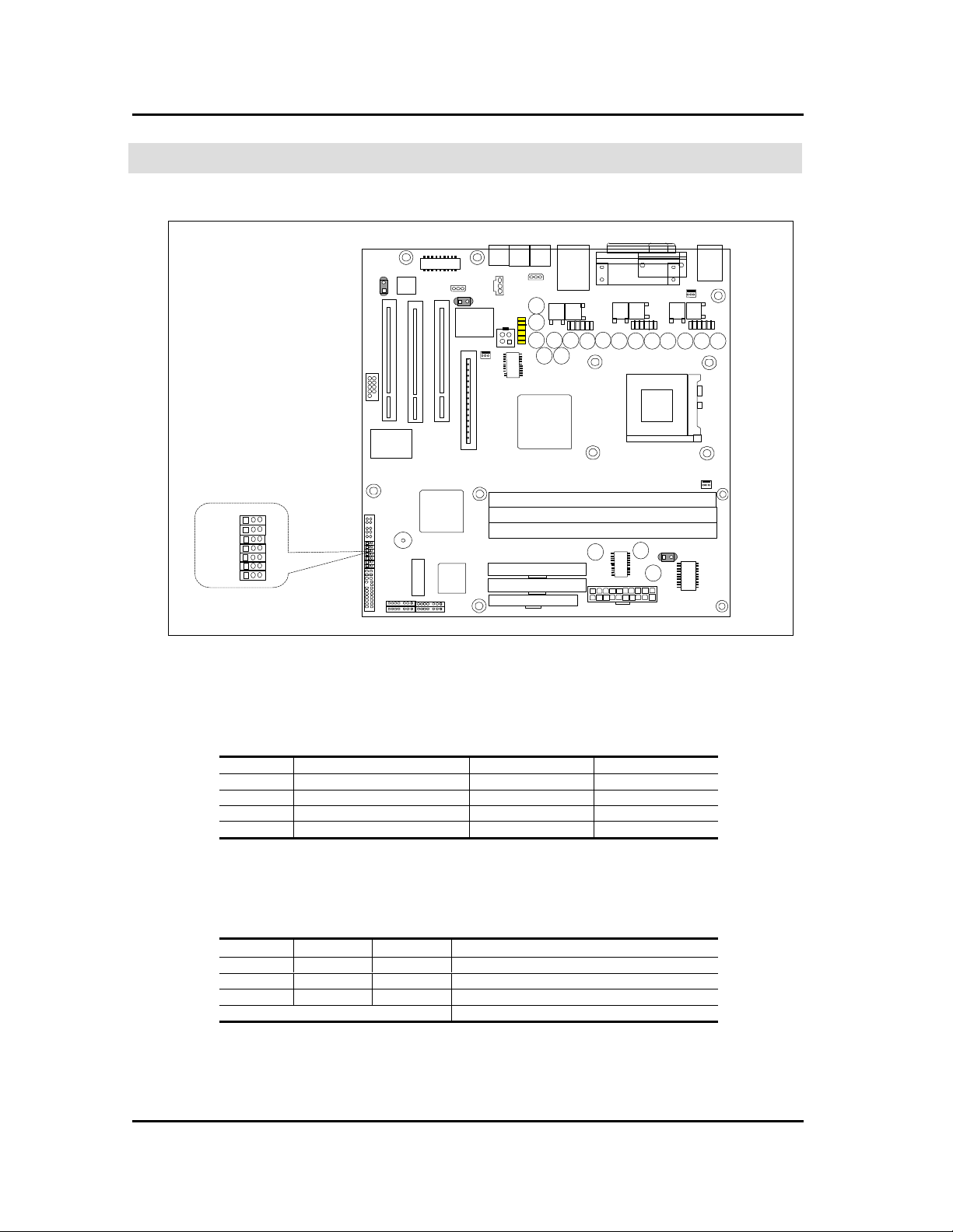
III. Jumpers & Connectors Descriptions
1. Motherboard Jumpers Settings
J3
J2
J1
J10
J11
1-1. Selection for Processor CPU Clock
& Intel Pentium-4 478 Pin Package Processor sets the core to bus frequency ratio for itself
1-2. Configuration Jumper Descriptions
Jumper Function 1-2 2-3
J1 CMOS Clear Normal CMOS Clear
J2
J3
J4
& Note : ‘1’ indicates connecting the Jumper pin #1 & #2, ‘0’ connecting Jumper pin #2 & #3.
CMOS Setup control Enable Disable
PASSWARD control Enable Disable
FDD Write Protection Normal Write Protection
1-3. OEM/ODM Selector (J12, J1 and J10)
The jumpers (J12, J11 & J10) are optional parts for the OEM/ODM logo message selector
J12 J11 J10
0 0 1 ODM
0 0 1 TriGem Export
0 1 0 TriGem Domestic
Others Reserved
& Note : ‘1’ indicates connecting the Jumper pin #1 & #2, ‘0’ connecting Jumper pin #2 & #3.
Type descriptions
TriGem Computer Inc. 11 / 16 Revision 0.9
Hardware Document
1 2 3
1 2 3
TGDFBD06-A Board Development Team
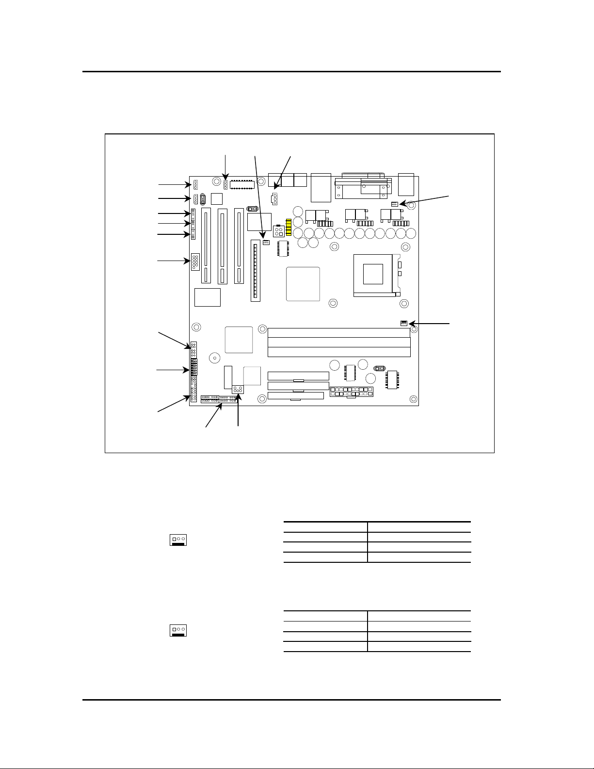
2. I/O Headers & Connectors Descriptions
2-1. Motherboard Internal Connectors
CN45
CN47
CN82
CN83
CN81
COM2
CN44 CN54 CN80
CN55
CN85
J4
J3
J2
J1
J10
J11
J12
CN71
CN73 CN23
q 1 : CPU FAN connector (CN53)
CN53
q 2 : Power Supply FAN connector (CN55)
CN105
CN53
Pin number Signal description
1 GND
2 FAN control
3 Tachometer (Speed)
Pin number Signal description
1 GND
2 FAN control
3 N.C
TriGem Computer Inc. 12 / 16 Revision 0.9

Hardware Document
1 2 3
8 7 6 5 4 3 2 1
9 10 17 18 15 14 12 11 20
TGDFBD06-A Board Development Team
q 3 : System Chassis FAN connector (CN54)
Pin number Signal description
CN54
q 4 : Indicator Header (CN73)
KEYLOCK RESET/SW SPEAKER
7 8
6 5 3 2 1
PWR HDD DC/SW SLEEP
CN73
q 5 : Joystick (CN71)
16 15 14 13 12 11 10 9
CN71
q 6 : USB (CN85)
CN85
Pin Signal description Pin Signal description
1 VCC 9 VCC
2 JAB(1) 10 JBB(1)
3 JACX 11 JBCX
4 GND 12 MIDI OUT
5 GND 13 JBCY
6 JACY 14 JBB(2)
7 JAB(2) 15 MIDI IN
8 VCC 16 Key
Pin Signal description Pin Signal description
1 GND 7 GND
2 Over Current detect2 8 Over Current detect3
3 Key 9 Key
4 USB2 – DATA 10 USB3 – DATA
5 USB2 + DATA 11 USB3 + DATA
6 GND 12 GND
1 GND
2 FAN control
3 Tachometer (Speed)
Pin Signal description
1 POWER/STR LED signal
2 GND
3 BLINK LED signal
4 NC
5 LED POWER
6 HDD access signal
7 GND
8 Power-ON switch signal
9 Suspend/Resume switch signal
10 GND
11 Key Lock signal
12 GND
13 NC
14 RESET switch signal
15 GND
16 NC
17 SPEAKER POWER
18 GND
19 NC
20 SPEAKER signal
TriGem Computer Inc. 13 / 16 Revision 0.9

Hardware Document
1 2 3
COM2
6 7 8 9 10
1 2 3 4 5
1 2 3
1 2 3
1 2 3 4
1 2 3 4
1 2 3 5
TGDFBD06-A Board Development Team
q 7 : AUX In –2nd CD-In (CN47)
CN47
q 8 : Serial port (COM2)
q 9 : Speaker Out (CN80)
CN80
q 10 : CD Sound In (CN44)
CN44
q
11 : Headphone In (CN82)
CN82
q 12 : MIC2 In (CN83)
CN81
CN83
q 13 : S/PDIF OUT (CN81)
q 14 : Video Sound-In (CN45)
Pin Signal description
1 LEFT
2 GND
3 RIGHT
Pin Signal description Pin Signal description
DCD 6 DSR
1
2 RXD 7 RTS
3 TXD 8 CTS
4 DTR 9 RI
5 GND 10 KEY
Pin Signal description
1 RIGHT
2 GND
3 LEFT
Pin Signal description
1 LEFT
2 GND
3 RIGHT
Pin Signal description Pin Signal description
1 RIGHT OUT 4 Key
2 Mute Control signal 5 LEFT OUT
3 GND
Pin Signal description Pin Signal description
1 GND 3 Key
2 MIC2 In signal 4 POWER
Pin Signal description Pin Signal description
1 S/PDIF DATA 3 NC
2 VCC 4 GND
TriGem Computer Inc. 14 / 16 Revision 0.9

Hardware Document
1 2 3 4
TGDFBD06-A Board Development Team
Pin Signal description Pin Signal description
1 LEFT 3 GND
2 GND 4 RIGHT
Pin Signal description
1 PC_PCI GNTA signal
2 GND
3 Key
4 PC_PCI REQA signal
5 GND
6 Serial IRQ signal
q
CN45
: PC_PCI Header (CN23)
15
1
3 5
6 4 2
CN23
TriGem Computer Inc. 15 / 16 Revision 0.9

Hardware Document
2 5
9
8
Note: This figure
is intentionally flipped
TGDFBD06-A Board Development Team
2-2. Motherboard External I/O Port
&
for explanation.
1
3
4
7
6
2. Line-OUT 7. Serial Port (COM1)
3. Line-IN 8. PS/2 Keyboard
4. MIC-IN 9. PS/2 Mouse
5. RJ45 Jack for LAN and 2*USB
1. Joystick/MIDI 6. Printer Port (LPT1)
Trademarks
Microsoft, Windows and Windows NT are registered trademarks of Microsoft Corporation.
Other product names used in this publication are for identification purpose only and may be trademarks of their
respective companies.
TriGem Computer Inc. 16 / 16 Revision 0.9
 Loading...