

Page 1
Page 2

BatterBatter
Batter
BatterBatter
y Wy W
arning Instructionarning Instruction
y W
arning Instruction
y Wy W
arning Instructionarning Instruction
Caution
If battery is incorrectly replaced there poses a danger of explosion. Replace battery
only with the same or equivalent type recommended by the manufacturer. Discard
used batteries according to the manufacturer's instructions.
Attention
Il y a danger d'explosion s'il y a remplacement incorrect de la batterie. Remplacer
uniquement avec une batterie du meme type ou d'un type recommande par le
constructeur. Mettre au rebut les batteries usagees conformement aux
instructions du fabricant.
Vorsicht
Explosionsgefahr bei unsachgemaβ em Austausch der Batterie. Ersatz nur durch
denselben oder einen vom Hersteller empfohlenen ahnlichen Typ. Entsorgung
gebraushter Batterien nach Angaben des Herstellers.
FF
use Wuse W
F
use W
FF
use Wuse W
arning Instructionarning Instruction
arning Instruction
arning Instructionarning Instruction
..
..
Caution
For continued protection against risk of fire, replace only with same type and rating
of fuse. Disconnect input power before servicing. Only connect this equipment to
an earthed socket outlet.
Vorsicht
Vor jeder service-arbeit netzstecker ziehen! Apparatet ma kun tilkobles jordet
stikkontakt.
Attention
Debrancher avant d'ouvrir. Apparaten skall anslutas till jordat natuttag.
Atencion
Desconecte fuerza electrica antes del servicio. Laite on liitettava
..
suojakosketinistoraasian.
..
..
..
Page 3

Declaration of Conformity (CE)Declaration of Conformity (CE)
Declaration of Conformity (CE)
Declaration of Conformity (CE)Declaration of Conformity (CE)
Application of Council Directives 89/336/EEC EMC Directive
Manufacturer TriGem Computer, Inc.
Manufacturer 1055 Shin-gil-Dong, Ansan City, Kyunggi
European Representative Name TriGem Computer (U.K.) Ltd.
European Representative Address 69 Bucking Ave. Trading Estate Slough
Equipment Type/Environment Motherboard
Model Name DT650 (Detroit)
Conformance to
We hereby declare that the equipment specified conforms to the above Directives.
Manufacturer Legal Representative in Europe
Full Name Full Name
Hyo-Geun Nam Hyun-Woo Choi
s Name
s Address
Do, Republic of Korea
Berkshire SL1 4PN U.K.
European International
EN 55022 (1995 Class B) CISPR 22 (1985 Class B)
EN 50082-1 (1992) IEC 801-2 (1984 Level 3)
EN 61000-3-2 (1995) IEC 801-3 (1984 Level 2)
EN 61000-3-3 (1995) IEC 801-4 (1988 Level 2)
Position Position
Team Leader President
Place Place
1055 Shin-gil-Dong, Ansan City, 69 Bucking Ave. Trading Estate
Kyunggi Do, Republic of Korea Slough Berkshire SL1 4PN U.K.
Date Date
March, 1998 March, 1998
Page 4

Chapter 1 IntroductionChapter 1 Introduction
Chapter 1 Introduction
Chapter 1 IntroductionChapter 1 Introduction
Features .............................................................................................................................. 1-1
Motherboard Overview.................................................................................................. 1-3
Chipset................................................................................................................................ 1-4
Super I/O Controller ...................................................................................................... 1-4
Motherboard Connectors ............................................................................................... 1-5
Expansion Connectors ........................................................................................... 1-6
Diskette Drive Connector (CN20) ..................................................................... 1-7
Enhanced IDE Connectors (CN22 and CN23)............................................... 1-7
ATX Primary Power Connector (CN24) ........................................................... 1-9
Front Panel I/O Connectors ............................................................................... 1-10
Back Panel I/O Connectors ................................................................................ 1-11
CONTENTS
Chapter 2 Using the Setup ProgramChapter 2 Using the Setup Program
Chapter 2 Using the Setup Program
Chapter 2 Using the Setup ProgramChapter 2 Using the Setup Program
About the Setup Program ............................................................................................... 2-1
Starting the Setup Program ............................................................................................ 2-2
Selecting Options .............................................................................................................. 2-3
Setup Menu ....................................................................................................................... 2-4
Standard Setup Menu ............................................................................................ 2-4
Advanced Setup Menu .......................................................................................... 2-6
Chipset Setup Menu .............................................................................................. 2-8
Power Control Setup Menu .................................................................................. 2-9
PCI/PnP Setup Menu ........................................................................................... 2-11
Peripheral Setup Menu ......................................................................................... 2-13
Utility Menu ...................................................................................................................... 2-15
Detect IDE .............................................................................................................. 2-15
Color Set .................................................................................................................. 2-15
Page 5

Security Menu................................................................................................................... 2-16
Supervisor/User ..................................................................................................... 2-16
Anti-Virus ................................................................................................................. 2-19
Default Menu ................................................................................................................... 2-19
Original ..................................................................................................................... 2-19
Optimal..................................................................................................................... 2-20
Exiting the SETUP Program.......................................................................................... 2-20
Chapter 3 Installing Motherboard OptionsChapter 3 Installing Motherboard Options
Chapter 3 Installing Motherboard Options
Chapter 3 Installing Motherboard OptionsChapter 3 Installing Motherboard Options
Before You Begin ............................................................................................................. 3-1
Changing the DIP Switch Settings ................................................................................ 3-2
Microprocessor................................................................................................................. 3-4
Installing the Retention Mechanism.................................................................... 3-5
Installing the Passive Heatsink Support Base ................................................... 3-7
Installing the Processor ......................................................................................... 3-8
Setting the DIP Switches for the Processor Speed .......................................... 3-9
Main Memory................................................................................................................... 3-9
Installing a Memory Module................................................................................ 3-10
Removing a Memory Module ............................................................................. 3-11
Replacing the Battery....................................................................................................... 3-12
Chapter 4 Update on Installing Windows 95Chapter 4 Update on Installing Windows 95
Chapter 4 Update on Installing Windows 95
Chapter 4 Update on Installing Windows 95Chapter 4 Update on Installing Windows 95
Installing the USB Supplement for Windows 95 ........................................................ 4-2
Installing the Bus Master IDE Driver for Windows 95........................................... 4-3
Enabling the Bus Master IDE Driver for Windows 95 ................................. 4-3
Page 6

Appendix A SpecificationsAppendix A Specifications
Appendix A Specifications
Appendix A SpecificationsAppendix A Specifications
Power Supply ..................................................................................................................... A-3
Appendix B Motherboard ResourcesAppendix B Motherboard Resources
Appendix B Motherboard Resources
Appendix B Motherboard ResourcesAppendix B Motherboard Resources
DMA Channels................................................................................................................. B-1
Interrupts ........................................................................................................................... B-2
FiguresFigures
Figures
FiguresFigures
Figure 1-1. Motherboard Overview ............................................................................. 1-3
Figure 1-2. Motherboard Connectors .......................................................................... 1-4
Figure 1-3. Connecting the Diskette Drive Connector Cable ................................. 1-7
Figure 1-4. Connectoring the IDE Cable .................................................................... 1-8
Figure 1-5. Connecting the Primary Power Supply Cable ........................................ 1-9
Figure 1-6. Front Panel Connectors ............................................................................. 1-10
Figure 1-7. Back Panel I/O Connectors ..................................................................... 1-11
Figure 1-8. Connecting Peripherals to the Back Panel Connectors ........................ 1-12
Figure 2-1. System Setup Window ................................................................................ 2-2
Figure 2-2. Exit Setup Window ...................................................................................... 2-20
Figure 3-1. Location of the DIP Switches .................................................................. 3-2
Figure 3-2. DIP Switch Setting ...................................................................................... 3-3
Figure 3-3. Installing the Processor Retention Mechanism (Type A) ..................... 3-5
Figure 3-4. Installing the Processor Retention Mechanism (Type B) ..................... 3-6
Figure 3-5. Inserting the Passive Heatsink Support Base ......................................... 3-7
Figure 3-6. Installing the Processor .............................................................................. 3-8
Figure 3-7. Installing the Heatsink Support Top Bar ................................................ 3-8
Figure 3-8. Releasing the Retaining Clips ..................................................................... 3-10
Figure 3-9. Installing a DIMM ...................................................................................... 3-11
Figure 3-10. Removing a DIMM ................................................................................. 3-12
Figure 3-11. Removing the Battery .............................................................................. 3-13
Figure 3-12. Installing the Battery ................................................................................. 3-13
Page 7

Chapter 1
Introduction
Introduction
FF
eatureseatures
F
eatures
FF
eatureseatures
Your mini-ATX motherboard provides the following built-in features:
Built-in Slot 1 processor connector (or microprocessor SEC cartridge
connector).
Support an Intel Pentium II processor that runs at an internal speed of
233, 266, 300, or 333 MHz and at an external speed of 66 MHz and Intel
Pentium II processor (Deschutes) that runs at internal speed of 300, 350, or
400 MHz and at an external speed of 100 MHz.
Introduction
Intel chip set that features Intel's 443BX AGPset with I/O subsystems.
Support LM78 hardware monitoring feature for optional chassis security
feature, temperature sensing, voltage monitoring, and fan status monitoring
feature.
Supports optional wake on ring and wake on LAN feature.
Built-in Ultra DMA/33 PCI Bus Mastering Enhanced IDE controller with two
connectors. These connectors support four IDE devices in two channels up to
33 MB/sec IDE transfers.
BIOS that supports both PCI and ISA Plug and Play (PnP), Desktop
Management Interface (DMI), Advanced Configuration and Power Interface
(ACPI), and Advanced Power Management (APM).
1-1
Page 8

Three 32-bit PCI bus slots, two 16-bit ISA slots, and one PCI/ISA shared slot
for either a PCI or ISA card.
AGP (Accelerated Graphics Port) slot that supports AGP cards with its own
graphics bus enhancing 3D performance.
Four DIMM sockets to expand up to 512 MB using 168-pin SDRAM DIMMs.
512 KB of pipelined burst level 2 (L2) cache included within the Pentium II
Single Edge Contact (SEC) cartridge.
Support for two functions of power button (ATX power supply required).
Support for an IrDA compliant Infrared interface module for wireless interface.
Bootable with CD-ROM drives, floptical drives, network drives, or SCSI drives.
Two high-speed UART-compatible serial ports and one parallel port with EPP
and ECP capabilities.
1-2
Introduction
Page 9
Motherboard OverMotherboard Over
S
r
connecto
Motherboard Over
Motherboard OverMotherboard Over
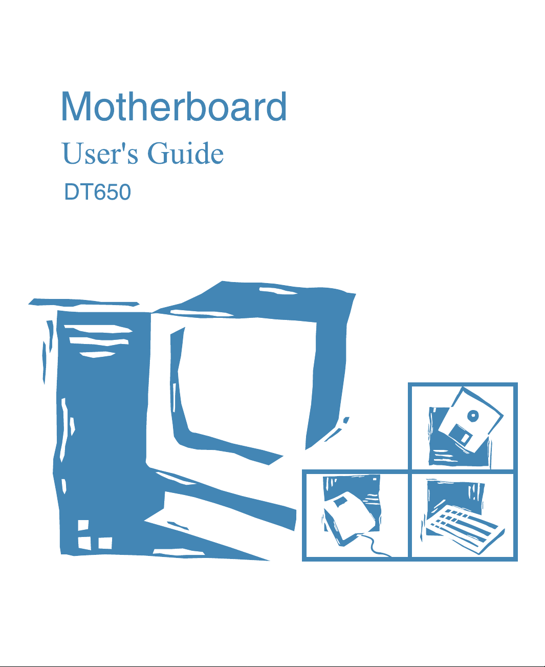
The illustration below shows the components on the motherboard.
viewview
view
viewview
PS/2 keyboard/mous e
connectors (stacked)
serial port 2 connector
parallel port connector
serial port 1 connector
Intel 82443BX (PAC)
ITE 8687 I/ O contr o l le r
ITE 8679 I/ O contr o l le r
lo t 1 proces sor
connector
USB connectors
jumper
PCI expansion
connectors
NSC LM78
BIOS RO M
ISA expansion
connectors
PC/PCI header
ATX auxiliary pow e r connector
ATX power connector
r
DIMM so ckets (DIMM0, D IMM 1
DIMM2, DIMM3 )
front panel connectors
secondary IDE connecto
primary IDE connector
CPU fan connector
accelerated graphics
port connector(AGP)
battery
DIP switc hes
jumpers
diskette drive connector
Intel 82371EB (PIIXE)
wake on ring connector
speaker
wake on LAN connector
chassis security
conn ector
system fan connector
IrDA connector
Introduction
Figure 1-1. Motherboard Overview
1-3
Page 10

ChipsetChipset
Chipset
ChipsetChipset
The Intel 443BX chipset is the third generation of desktop PCIset and is designed
for the Pentium II processor. It consists of the Intel 82443BX PCI/AGP controller
(PAC) and the Intel 82371EB PCI/ISA IDE Xcelerator (PIIX4E) bridge chip.
Intel 82443BX PCI/AGP Controller (PAC)
The PAC provides bus-control signals, address paths, and data paths for transfers
between the processors host bus, PCI bus, Accelerated Graphics Port (AGP), and
main memory.
Intel 82371EB PCI ISA IDE Xcelerator (PIIX4E)
The PIIX4E is a multifunction PCI device implenting the PCI-to-ISA bridge, PCI
IDE functionality, Universal Serial Bus (USB) host/hub function, and enhanced
power management.
Super I/O ControllerSuper I/O Controller
Super I/O Controller
Super I/O ControllerSuper I/O Controller
The IT8679 Super I/O controller from ITE is an ISA Plug and Play Compatible,
multifunction I/O device that provides the serial ports, multimode bidirectional
parallel port, diskette drive controller, keyboard and mouse controller, and IrDA
interface features.
By default, the I/O controller interfaces are automatically configured during boot
up. The I/O controller can also be manually configured in the SETUP program.
1-4
Introduction
Page 11
Motherboard ConnectorsMotherboard Connectors
S
(C
)
r
Motherboard Connectors
Motherboard ConnectorsMotherboard Connectors
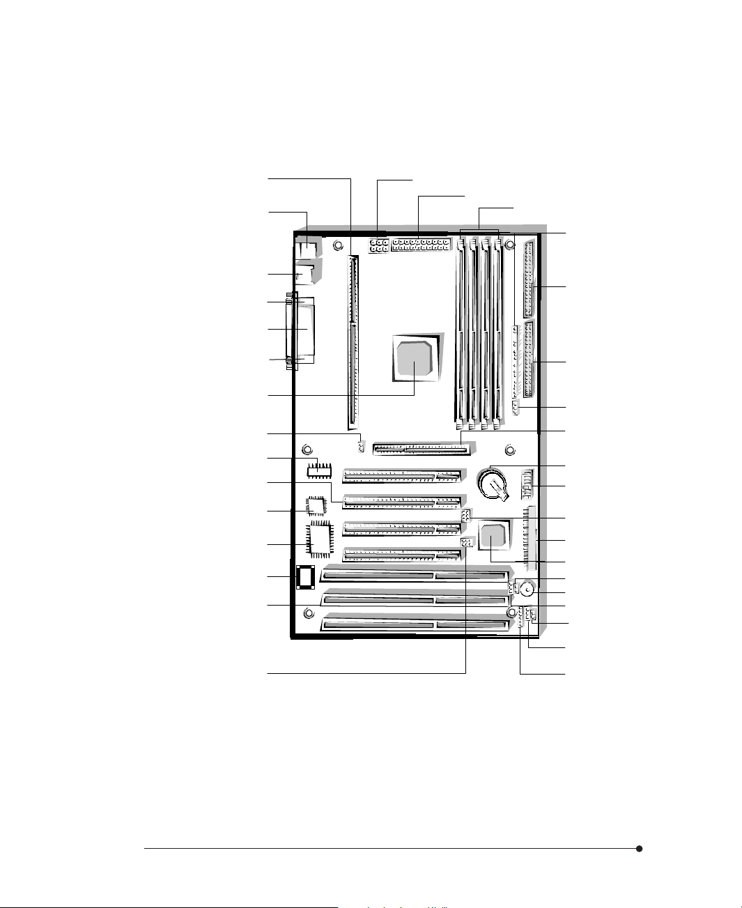
The illustration below shows the connectors on the motherboard.
PS/2 keyboard/mous e
connectors (stacked)
USB connectors (CN13)
serial port 2 connector
parallel port connector
serial port 1 connector
(CN4, CN5, CN6, CN7)
(CN1, CN2, CN3)
lo t 1 proces sor
connector (CN9)
(CN14)
(CN12)
(CN11)
(CN10)
PCI expansion
connector
ISA exp ansi on
connectors
PC/PCI header
connector (JP1)
IrDA connector
(CN32)
*
* manufacturing options
ATX auxiliary pow e r connector
ATX power connector (CN24)
DIMM sockets (CN16, CN15,
CN17, CN18 )
N35
front panel connector
(CN34)
secondary IDE connecto
(CN23)
primary IDE connector
(CN22)
CPU fan connector
(CN29)
accelerated graphics
port connector(AGP)
(CN8)
diskette drive connector
(CN20)
wake on ring connector
(CN33)
*
speaker
wake on LAN connector
*
(CN19)
chassis security
connector (CN26)
system fan connector
(CN27)
*
Figure 1-2. Motherboard Connectors
Introduction
1-5
Page 12

Expansion Connectors
Your motherboard contains two 16-bit ISA option slots, three 32-bit PCI option
slots, one PCI/ISA shared slot (CN3 and CN4), and one AGP slot. You can install a
maximum of six option cards, since one PCI and ISA slot share the same chassis I/
O panel.
You can simply install PnP-compliant PCI or ISA option cards without setting
jumpers or switches or performing other configuration tasks by plug and play
capacity. If you turn on the computer after adding PnP-compliant cards, the BIOS
will automatically configure interrupts, I/O space, and other parameters.
See the option card manual that comes with the option card or your system manual
for information on installing or removing option cards.
ISA Expansion Connectors (CN1, CN2, CN3)
You can install ISA option cards to the connectors.
PCI Expansion Connectors (CN4, CN5, CN6, CN7)
You can install PCI option cards to the connectors.
1-6
AGP (Accelerated Graphics Port) Connector (CN8)
Accelerated Graphics Port is a dedicated graphics bus with higher bandwidth, which
allows texturing from main memory. By providing high-bandwidth access to
memory, AGP enables a new level of sophisticated graphics allowing software
developers to create richer, more inviting 3D environments with higher resolutions
than ever before.
Introduction
Page 13
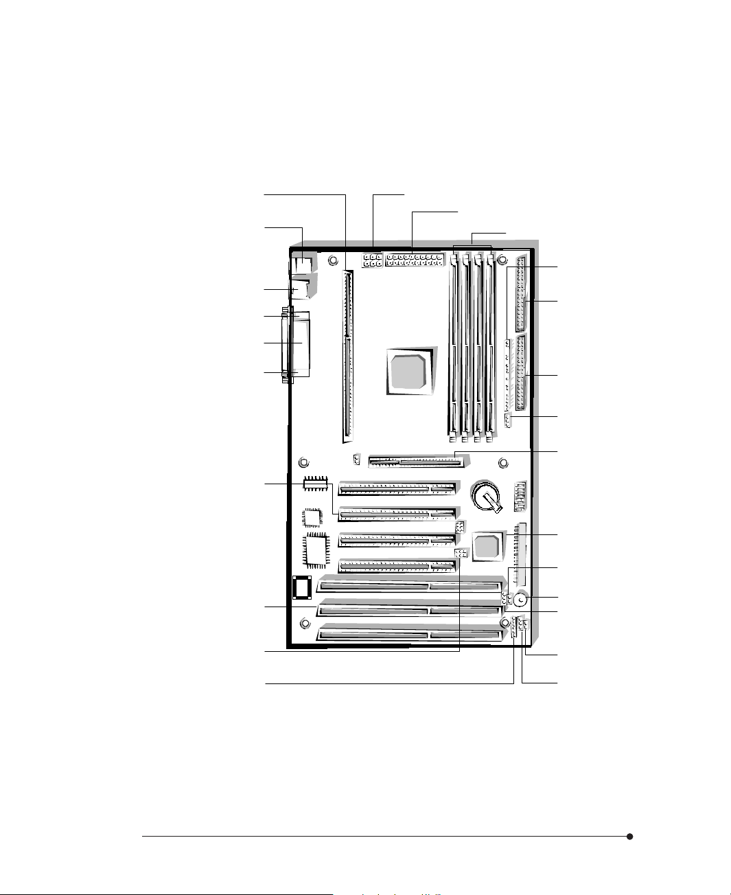
Diskette Drive Connector (CN20)
You can connect up to two diskette drives to the diskette drive connector. After
connecting the one end of the diskette drive ribbon cable to the motherboard,
connect the two connectors on the other end to the diskette drives.
Figure 1-3. Connecting the Diskette Drive Connector Cable
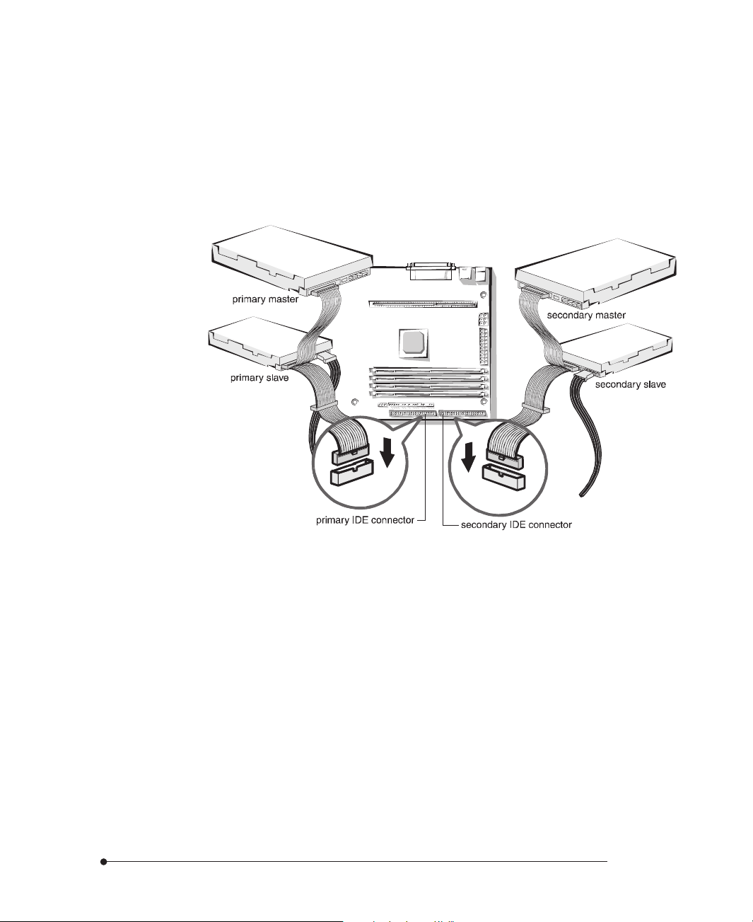
Enhanced IDE Connectors (CN22 and CN23)
You can connect up to four IDE devices (hard disk drives, CD-ROM drives, and
floptical drives) to the two IDE connectors (primary and secondary).
The PCI Bus Mastering IDE controller supports PIO Mode 3 and 4, and Ultra
DMA/33, a DMA data transfer protocol for IDE devices such as hard disk drives
or CD-ROM drives. The Ultra DMA/33 allows DMA commands to transfer data
at a maximum burst rate of 33 MB/sec. IDE devices must be capable of
supporting Ultra DMA/33 in order to enable this feature. Also, an Ultra DMAaware device driver (a Bus Master IDE driver) for your operating system is
required.
Introduction
1-7
Page 14
The BIOS in the motherboard supports bootup from IDE CD-ROM drive,
floptical drive, SCSI drive or network drive. So, you can select a CD-ROM drive or
floptical drive as a boot device by setting CD-ROM or Floptical in the Advanced
Setup menu of the SETUP program.
After connecting the one end of the IDE ribbon cable to one of the IDE
connectors on the motherboard, connect the two connectors at the other end to
your hard disk drives.
1-8
Figure 1-4. Connecting the IDE Cable
If you install two hard disks, you must configure the second drive to slave mode by
setting its jumper accordingly. See the manual of your hard disk for the jumper
settings.
You may configure two hard disk drives to be both masters using one ribbon cable
on the primary IDE connector and another ribbon cable on the secondary IDE
connector. You may install one operating system on an IDE drive and another on
the other IDE drive and select the boot device through SETUP.
If you set up your CD-ROM drive as the primary master drive and boot the
system from the CD-ROM drive, the system will recognize the CD-ROM drive as
drive A and your drive A as drive B, and can not recognize your drive B.
Introduction
Page 15
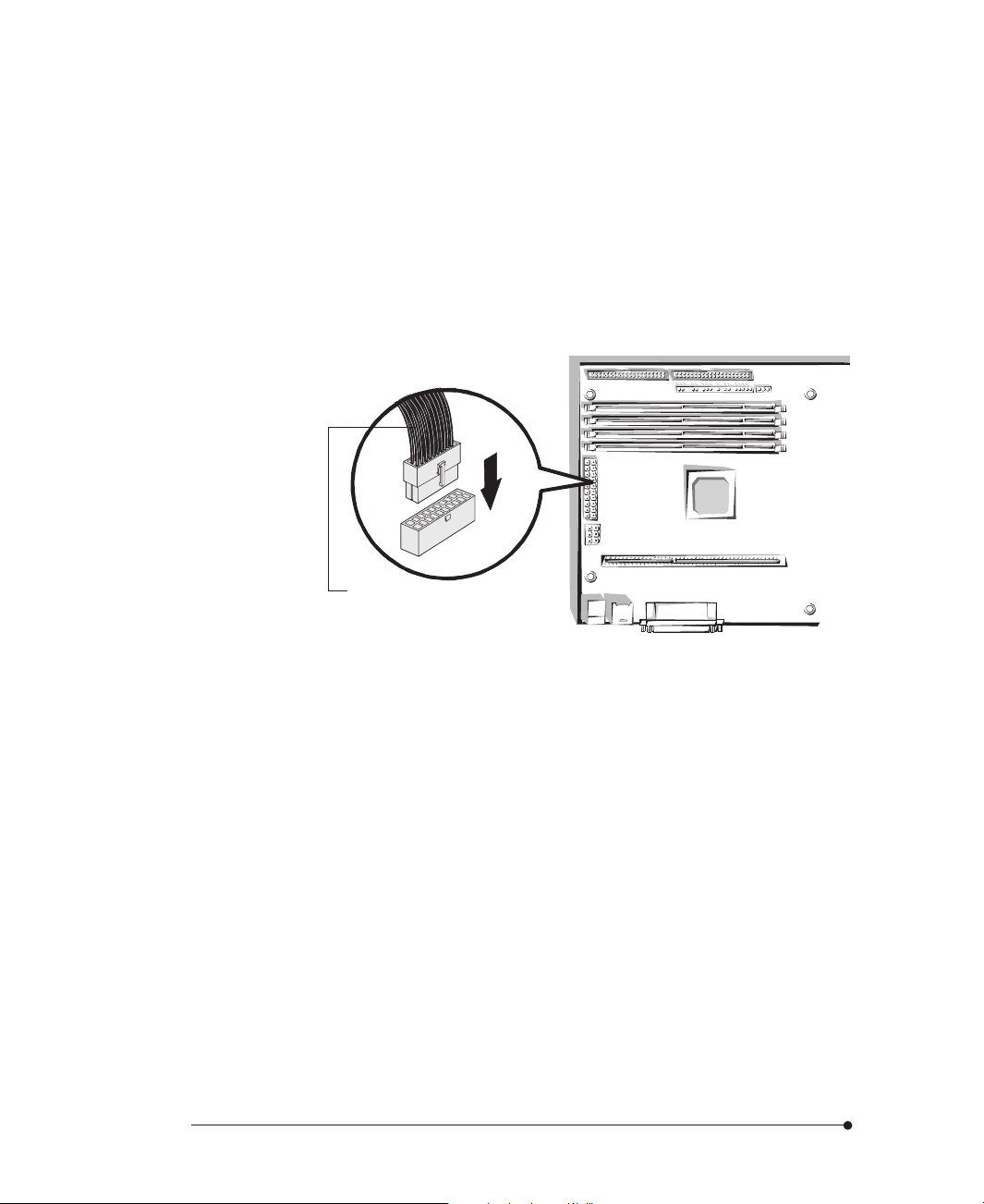
ATX Primary Power Connector (CN24)
You can connect an ATX-compliant power supply to the 20-pin block ATX power
connector. Connect the cable from the power supply to this connector. Make sure
that the cable from the power supply is aligned with the power connector on the
motherboard and then firmly push down the cable.
When using an ATX-compliant power supply that supports ATX specification 2.1,
connect the auxiliary power cable from the power supply to the 6-pin block auxiliary
power connector next to the ATX primary power connector.
ATX power connector cable
Introduction
Figure 1-5. Connecting the Primary Power Supply Cable
1-9
Page 16
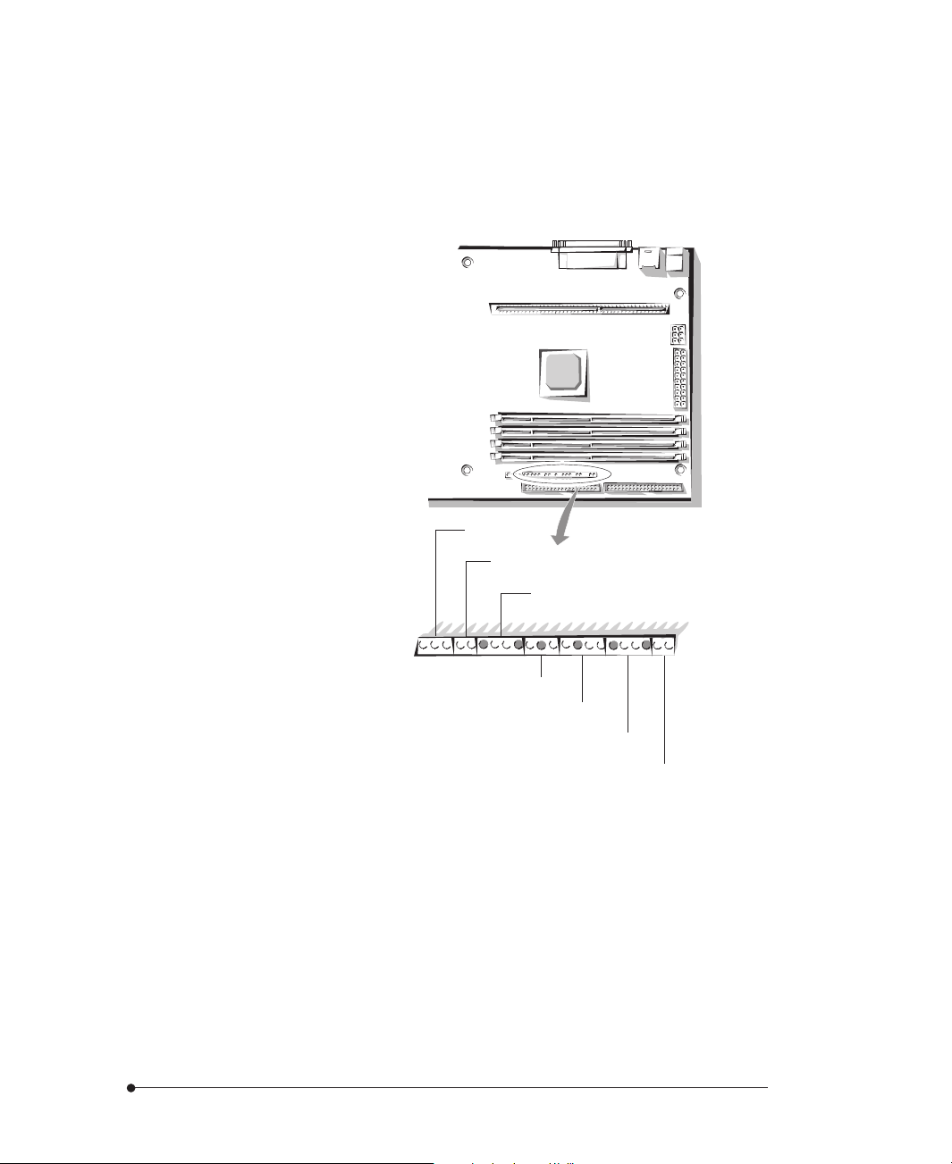
Front Panel I/O Connectors
The motherboard provides header connectors to support functions typically located
on the front panel of the computer and the illustration below shows the front panel
I/O connectors.
power LED
HDD LED
speaker
1-10
keyboard lock
reset switch
suspend switch
power switch
Figure 1-6. Front Panel Connectors
Introduction
Page 17
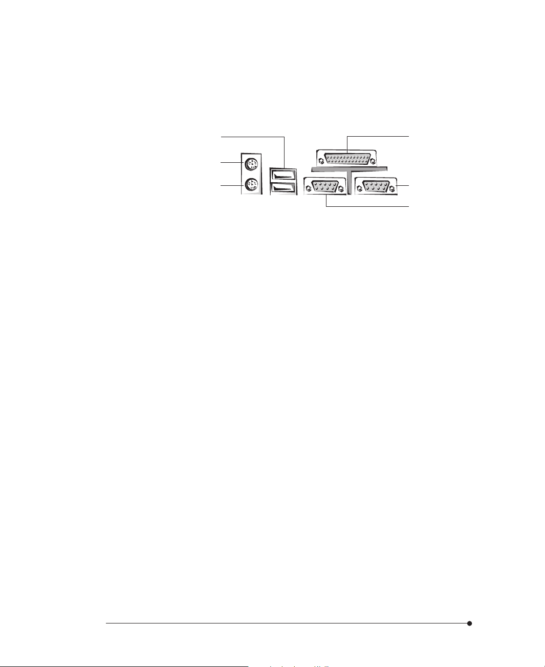
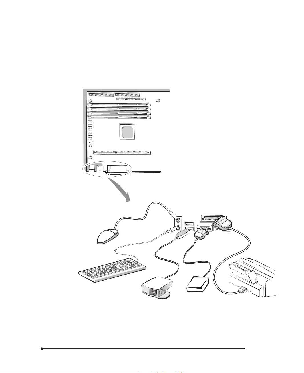
Back Panel I/O Connectors
The illustration below shows back panel connectors that are located on the edge
side of the motherboard.
USB connectors
(CN13)
PS/2 mouse
connector (CN14)
PS/2 keyboard
connector (CN14)
Figure 1-7. Back Panel I/O Connectors
Serial Port 1 and 2 Connectors (CN10, CN12)
You can connect serial devices such as a mouse, an external modem, or a serial
printer to either serial ports. By default, any device connected to the serial port 1
connector (the serial port 2 connector) is designated in software as COM1
(COM2). You can change these designations through the SETUP program.
Parallel Port Connector (CN11)
You can connect parallel devices such as a printer to the parallel port. By default,
any device connected to this port is designated in software as LPT1. You can set the
I/O address used by this port through the SETUP program.
parallel port (CN11)
serial port 1 connector
(CN10)
serial port 2 connector
(CN12)
Introduction
USB Connectors (CN13)
You can connect peripherals such as scanners, printers and joysticks to the USB
(Universal Serial Bus) connectors. USB includes devices that in the past used serial
ports, parallel ports, the keyboard port, the mouse port, and game ports as well as
new kinds of devices. USB peripherals are hot-swappable enabling plug and play for
your peripherals.
1-11
Page 18
PS/2 Keyboard Connector (CN14)
The PS/2 keyboard is connected to the connector.
PS/2 Mouse Connector (CN14)
The PS/2 mouse is connected to the connector.
1-12
mouse
keyboard
modem (serial device)
CCD camera (USB device)
printer (parallel device)
Figure 1-8. Connecting Peripherals to the Back Panel Connectors
Introduction
Page 19

Chapter 2
Using the SETUP Program
Using the SETUP Program
About the SETUP ProgramAbout the SETUP Program
About the SETUP Program
About the SETUP ProgramAbout the SETUP Program
You can use the SETUP program to change the computer's configuration
information when you installed or removed motherboard options.
The SETUP program is stored in your motherboard's read-only memory (ROM),
so you can run the program any time you turn on or reset the computer. You don't
need to insert a diskette or access a hard disk.
The configuration you define through SETUP is stored in a special area of memory
called CMOS RAM. The battery on the motherboard backs up this memory, so the
memory is not erased when you turn off or reset the computer. Whenever you
reboot the computer, it checks the settings, and if it discovers a difference between
the information in the CMOS RAM and its actual hardware configuration, it
prompts you to run SETUP.
Using the SETUP Program
2-1
Page 20

StarStar
Star
StarStar
ting the SETUP Pting the SETUP P
ting the SETUP P
ting the SETUP Pting the SETUP P
To start SETUP, turn on the computer. After the computer completes its self-test,
as soon as you see the message, press the Del key:
Hit DEL if you want to run SETUP
If you do not press Del quickly, the computer starts loading the operating system
and you will not be able to run SETUP. If happens, reset the computer again.
When you enter the SETUP program, you see the System Setup window.
SETUP is composed of four windows that contain several icons. An information
line at the bottom of the menu displays simple explanations for each option.
rogramrogram
rogram
rogramrogram
2-2
Figure 2-1. System Setup Window
Using the SETUP Program
Page 21

Selecting OptionsSelecting Options
Selecting Options
Selecting OptionsSelecting Options
You can use the keyboard or mouse to select the options.
The mouse functions in SETUP are click (change or select both global and current
fields) or double click (perform an operation in selected field).
The table lists keyboard functions in SETUP:
Key Function
Tab
→ , ← , ↑, ↓
Enter
+ Increases a value.
- Decreases a value.
Esc
PgUp Returns to the previous screen.
PgDn Advances to the next screen.
Home Returns to the beginning of the text.
End Advances to the end of the text.
Alt-H
Alt-Spacebar Exits System Setup.
Alphabetic keys A to Z are used in the keyboard.
Numeric keys 0 to 9 are used in either the numeric keys along the
Changes or selects a global field.
Change or select the current field.
Performs an operation in the current field.
Aborts any window function.
Accesses a help window. It describes the keys
available in SETUP.
top of the keyboard or the numeric keypad.
Using the SETUP Program
2-3
Page 22

Setup MenuSetup Menu
Setup Menu
Setup MenuSetup Menu
The Setup menu has 6 icons, each of which contains a submenu.
Standard Setup Menu
If you select the Standard icon, you will see the submenu.
Pri Master/Pri Slave/Sec Master/Sec Slave
Select one of these icons to configure the hard disk drive named in the options.
When you select one of these icons, the parameters are listed: Type, LBA/Large
Mode, Block Mode, 32Bit Mode, and PIO Mode.
Type
The drive parameters and settings are:
Parameter Description
Type The number for a drive with certain identification parameters.
Cyl The number of cylinders on the disk.
Hd The number of read/write heads in the drive.
WP The write precompensation cylinder.
Sec The number of sectors per track on the disk.
Size (MB)
The total amount of storage capacity on the disk (selected
automatically). Actual size when formatted may be slightly
different than the size listed on the drive label.
2-4
Using the SETUP Program
Page 23

Setting Description
User If the parameters for your hard disk drive do not match any of
the types listed, or your hard disk drive is a non-IDE one, select
User to define your own type. You must type the correct drive
parameters on the window that you selected.
Auto If your drive(s) is an IDE drive and you select Auto, BIOS will
automatically detect your IDE drives including ATAPI CD-ROM
drives and floptical drives during bootup and display Auto
Detection Status window. Click OK to accept parameters on the
window. If Auto is set for Type, LBA/Large Mode, Block Mode,
and PIO Mode are automatically set.
CD-ROM If a CD-ROM drive is connected to the IDE connector, select
CD-ROM. You can load your operating system from the CD-ROM
drive. You can also choose Auto and it lets BIOS automatically set
the correct drive parameters.
Floptical If a floptical drive is connected to the IDE connector, select
FLOPTICAL for the drive. You can boot the computer from the
floptical drive.
LBA/Large Mode
Set this option to On to use 528MB or greater of hard disk drives. The settings are
On and Off.
Block Mode
To enable multiple sector read/write on IDE drives, set this option to On. The
settings are On and Off.
32Bit Mode
If you set this option to On, it enables 32-bit data transfer to IDE data port in IDE
drives. If you set this option to Off, it enables 16-bit data transfer. The settings are
On and Off.
PIO Mode
This option sets how fast transfers on the IDE interface occur. PIO (programmed
I/O) works with ATAPI CD-ROM drives. The settings are Auto, 0, 1, 2, 3 and 4.
Select Auto to allow SETUP to automatically detect the PIO mode that IDE drives
use. If you set this option to Auto, transfers occur at the drive's maximum speed. If
you want to select one of 0 to 5, make sure you are selecting the PIO mode
supported by the IDE drive.
Using the SETUP Program
2-5
Page 24

Date/Time
Use the Date/Time option to change the date or time. Enter the correct time or
date using + or - key. You can only reset the number of seconds to 00.
Floppy A and B
Select Floppy A or Floppy B to specify the floppy drive type. The settings are Not
Installed, 360KB 5 1/4, 1.2MB 5 1/4, 720KB 3 1/2, 1.44MB 3 1/2, and 2.88MB
3 1/2.
Advanced Setup Menu
The Advanced Setup menu is displayed by choosing the Advanced icon from the
Setup menu.
Quick Boot
This option determines whether the computer boot quickly when it is turned on or
not. If you select Enabled, the computer runs its self test without performing more
than 1MB of system memory test, floppy seek test, and keyboard test. The settings
are Disabled and Enabled.
2-6
1st Boot Device
This option sets the type of the first boot drive the computer checks first to find an
operating system to boot from. The settings are Disabled, IDE-0, IDE-1, IDE-2,
IDE-3, Floppy, Floptical, CDROM, SCSI, and Network.
2nd Boot Device
This option sets the type of the second boot drive the computer checks second to
find an operating system to boot from. The settings are Disabled, IDE-0, Floppy,
Floptical, and CDROM.
Using the SETUP Program
Page 25

3rd Boot Device
This option sets the type of the third boot drive the computer checks third to find
an operating system to boot from. The settings are Disabled, IDE-0, Floppy,
Floptical, and CDROM.
BootUp Num-Lock
This option determines the beginning state of the NumLock feature on your
keyboard, when system is turned on or reset. The settings are On and Off.
PS/2 Mouse Support
If you enable this option, you can use a PS/2 mouse. The settings are Disabled and
Enabled.
Primary Display
This option lets you define the type of adapter you are using for your primary
display. The settings are Absent, VGA/EGA, CGA40X25, CGA80X25, and Mono.
Password Check
This option sets the type of password protection. The settings are Setup and
Always. If you select Setup, every time you run SETUP, the computer checks your
password. Once you set password, you should enter your password whenever you
run SETUP.
If you select Always, every time you run SETUP or turn on or reset the computer,
it checks your password.
Boot To OS/2
If your system has more than 64MB of main memory and OS/2 operating system
installed, set this option to Yes. The settings are Yes and No.
Using the SETUP Program
2-7
Page 26

Internal Cache
The option sets the type of caching algorithm used by your microprocessor for
internal L1 cache memory. The settings are Disabled and Enabled.
C000 / C400, 16K Shadow
These options allow you to shadow the contents of video ROM listed in the option
titles to the system's RAM. Cached enables the contents of the video ROM area to
be written to the corresponding RAM or cache memory. The settings available for
these options are Disabled, Enabled and Cached.
C800 / CC00 / D000 / D400 / D800 / DC00, 16K Shadow
These options allow you to shadow the contents of the adapter ROM listed in the
option titles to the system's RAM. Cached enables the contents of the ROM area to
be written to the corresponding RAM or cache memory. The settings available for
these options are Disabled, Enabled and Cached.
Chipset Setup Menu
If you select the Chipset icon from the Setup main menu, the Chipset Setup menu
is displayed.
2-8
Memory Hole
This option specifies the location of an area of memory that cannot be addressed
on the ISA bus. The settings are Disabled, 512KB-640KB and 15MB-16MB.
Graphics Aperture Size
This option specifies the amount of system memory that can be used by the AGP.
The settings are 4MB, 8MB, 16MB, 32MB, 64MB, 128MB and 256MB.
Using the SETUP Program
Page 27

Power Control Setup Menu
If you select the Power Ctrl icon from the Setup main menu, the Power Control
Setup menu is displayed.
Power Management / APM
Set the option to Enabled to enable the power management and APM (Advanced
Power Management) features. If you set Disabled for the option, you will not see
any options in the Power Control Setup menu. The settings are Disabled and
Enabled.
Power Button Function
The option allows holding the power button on the computer to enter suspend
mode as well as functioning as a normal on/off feature of the power button. It
takes effect after finishing power-on self test. The settings are Suspend and On/
Off.
From power-on until power-on self test, you should press the power button for
more than 4 seconds to turn off your system. However, after finishing power-on
self test, the methods for turning off the system depend on the setting for the
option.
When the option is set to Suspend, you should press the power button for more
than 4 seconds to turn off the system after finishing power-on self test. At this
time, if you press the power button for less than 4 seconds, the computer will go
into suspend mode. When the option is set to On/Off, normally pressing the power
button after power-on self test makes the system turned off.
If the Power Management / APM option is set to Disabled, the Power Button
Function option can be used only as a normal On/Off feature.
NoteNote
Note
NoteNote
If you press the power button for more than 4 seconds while in suspend mode to
turn off the system, the system will restart. So, we recommend you turn off the
system after resuming the system when turning it off.
Using the SETUP Program
2-9
Page 28

AC Power Default Status
This option specifies whether the system will boot up after a power failure. If you
select On, the system power will be restored. If you select Off, the system power
will be still off until you press the power button. The settings are On and Off.
Remote Power On LAN
This option allows the computer to respond to a LAN wakeup event when the
power is off. The settings are Disabled and Enabled.
Remote Power On Modem
This option allows the computer to respond to an incoming call on an installed
modem when the power is off. The settings are Disabled and Enabled.
Suspend Time Out
The option specifies the length of the period of system inactivity for going into
suspend mode. When the specified period of system inactivity expires, the
computer will enter suspend mode, beeping twice. If there are activities of devices
described below during suspend mode, the computer will exit the suspend mode.
You can make your setting using + or - key. The settings are Disabled and every 4th
value between 4 and 508 minutes.
2-10
Device 6 (Serial port 1)
When the computer is in suspend mode, the option sets whether or not the
computer monitors the activity of devices connected to the serial port 1. The
settings are Ignore and Monitor.
Device 7 (Serial port 2)
When the computer is in suspend mode, the option sets whether or not the
computer monitors the activity of devices connected to the serial port 2. The
settings are Ignore and Monitor.
Device 8 (Parallel port)
When the computer is in suspend mode, the option sets whether or not the
computer monitors the activity of devices connected to the parallel port. The
settings are Ignore and Monitor.
Using the SETUP Program
Page 29

Device 5 (Floppy disk)
When the computer is in suspend mode, the option sets whether or not the
computer monitors the activity of diskette drives in the system. The settings are
Ignore and Monitor.
Device 0, 1, 2, 3 (Primary master IDE, Primary slave IDE, Secondary
master IDE, Secondary slave IDE)
When the computer is in suspend mode, the options set whether or not the
computer monitors the activity of each of four IDE drives connected to each
channel named in the options. The settings are Ignore and Monitor.
NoteNote
Note
NoteNote
When the system is in suspend mode, it always monitors the activities of the
keyboard or mouse.
PCI/PnP Setup Menu
If you select the PCI/PnP icon from the Setup main menu, the PCI/PnP Setup
menu is displayed.
Plug and Play Aware O/S
The option enables the computer to boot with an operating system capable of
managing Plug and Play option cards. Set it to Yes if the operating system (such as
Windows 95) installed in the computer follows the Plug and Play specification.
Windows 95 is PnP-aware. The Windows 95 operating system detects and enables
all other PnP-aware adapter cards. Set the option to No if the operating system
(such as DOS, OS/2, Windows 3.0, or Windows NT 4.0) does not use PnP. You
must set this option correctly, or PnP-aware adapter cards installed in the computer
will not be configured properly. The settings are Yes and No.
Using the SETUP Program
2-11
Page 30

PCI Latency Timer (PCI Clocks)
This option sets the length of time (measured in the number of PCI clock cycles)
that a PCI device on the PCI bus can hold the bus when another device has
requested the bus. The settings are 32, 64, 96, 128, 160, 192, 224, and 248.
PCI VGA Palette Snoop
The option controls the ability of a primary PCI graphics controller to share a
common palette with an ISA video adapter card. The settings are Disabled and
Enabled.
Allocate IRQ to PCI VGA
This option allows BIOS to allocate an IRQ for the VGA controller on the PCI bus.
The settings are Yes and No.
Allocate IRQ to USB
This option allows BIOS to allocate an IRQ for the UBS controller on the PCI bus.
The settings are Yes and No.
DMA Channel 0, 1, 3, 5, 6, and 7
These options allow you to specify the bus type used by each DMA channel for
legacy(non-PnP) ISA option cards. The settings are PnP and ISA.
2-12
IRQ 3, 4, 5, 7, 9, 10, 11, 14, and 15
These options set the bus type used by each IRQ. These options allow you to
reserve IRQs for legacy ISA adapter cards. If these interrupts are available for use
by PCI/PnP option cards, the interrupts are assigned for the computer to use. If
the computer contains an ISA option card that uses one of these interrupts, select
ISA for that interrupt. The settings are PCI/PnP and ISA.
Using the SETUP Program
Page 31

Peripheral Setup Menu
The Peripheral Setup menu is displayed if you select the Peripheral icon from the
Setup main menu.
OnBoard FDC
Set this option to Enabled to enable the built-in diskette drive controller. If you
install another FDC card, disable this option. The settings are Auto, Disabled, and
Enabled.
OnBoard Serial Port 1
This option specifies the base I/O port address of built-in serial port 1. The settings
are Auto, Disabled, 3F8h, 2F8h, 3E8h, and 2E8h.
OnBoard Serial Port 2
This option specifies the base I/O port address of built-in serial port 2. The settings
are Auto, Disabled, 3F8h, 2F8h, 3E8h, and 2E8h.
Serial Port 2 Mode
This option specifies the operating mode for serial port 2 for normal (COM2) or
infrared applications. It only appears when the OnBoard Serial Port 2 option is not
set to Auto or Disabled. The settings are Normal, IrDA, ASKIR (Amplitude Shift
Keyed Infrared), MIR 0.5 Mbps, MIR 1.1 Mbps, and FIR (Fast Infrared).
Set this option to IrDA to enable an IrDA module connected to IrDA connector
(CN32) on the motherboard. The IrDA specification provides for data transfers at
115Kbps from a distance of 1 meter.
Using the SETUP Program
2-13
Page 32

Duplex Mode
This option specifies the transmission method for serial port 2. The settings are Full
and Half. Full is simultaneous transmission mode and Half is sequential
transmission/receiving mode.
OnBoard Parallel Port
It specifies the base I/O port address for the built-in parallel port. The settings are
Auto, Disabled, 378, 278, and 3BC.
Parallel Port Mode
It specifies the mode for the parallel port. The settings are Normal, EPP, and ECP.
Settings Function
Normal
EPP
ECP
Normal means the parallel port operates in the standard ATcompatible parallel port mode.
The parallel port can be used with devices that adhere to the
Enhanced Parallel Port (EPP) specification. EPP uses the existing
parallel port signals to provide asymmetric bi-directional data
transfer driven by the host device.
The parallel port can be used with devices that adhere to the
Extended Capabilities Port (ECP) specification. ECP uses the DMA
protocol to achieve data transfer rates of 2.5 Mbs. ECP
provides symmetric bi-directional communication.
2-14
Parallel Port IRQ
This option specifies the IRQ used by the parallel port. It is only available when the
OnBoard Parallel Port option is not set to Auto. The settings are 5 and 7.
Parallel Port DMA Channel
This option sets the DMA channel used by the parallel port. It is only available if
the setting for the Parallel Port Mode option is ECP. The settings are 0, 1, and 3.
Using the SETUP Program
Page 33

OnBoard IDE
The option allows you to set the built-in IDE controller you want to use. The
settings are Disabled, Primary, Secondary, and Both.
Utility MenuUtility Menu
Utility Menu
Utility MenuUtility Menu
There are 2 icons in the Utility menu.
Detect IDE
If an IDE-type hard disk drive, a CD-ROM drive, or a floptical drive is connected
to the primary or secondary IDE controller, this option allows for automatic
detection of the hard disk drive or CD-ROM drive type. Once SETUP detects the
type of the hard disk or CD-ROM drive installed, it will display the relative
information.
After SETUP detects all IDE drives, the hard disk drive type will be forced to be
User and the CD-ROM drive type will be forced to be CDROM.
Color Set
This option allows you to change the color of the System Setup window. The setting
are Sky, Army, Pastel, and LCD.
Using the SETUP Program
2-15
Page 34

Security MenuSecurity Menu
Security Menu
Security MenuSecurity Menu
Three icons appear in the Security menu.
Supervisor / User
These two options make it possible to restrict access to the SETUP program and to
restrict who can boot the computer by enabling you to set passwords for two
different access modes: Supervisor mode and User mode.
A Supervisor password and a User password can be set for the SETUP program
and for booting the computer.
Supervisor mode has full access to all the SETUP options whereas User mode has
limited access to the options. Setting separate Supervisor and User passwords
enables a system supervisor to restrict who can change critical SETUP values.
When you run SETUP by entering your User password, you can change the three
items only: Advanced, User, and Color Set.
If you set both the Supervisor and User passwords, you must set the Supervisor
password first. Once both are set, you can enter either the Supervisor password or
the User password to access SETUP or the computer.
2-16
The system can be configured so that all users can enter a password every time you
turn on or reset the system, or run SETUP, using Supervisor password only or both
passwords.
The table shows the effects of setting the Supervisor and User passwords.
Supervisor and User password functions
Password set Password during
boot
Neither None
Supervisor and
User set
Supervisor only
Supervisor or
User
Supervisor Supervisor Can change
Password to
enter SETUP
None Can change
Supervisor or
User
Supervisor
mode
all options
Can change
all options
all options
Using the SETUP Program
User mode
Can change
all options
Can change a
limited
number of
options
-
Page 35

Setting a Password
Follow these steps to set your password:
When you see "Enter New Password" in the Supervisor or User window, type
1
the letter you want to use using the keyboard or click it using the mouse. You
can type up to six characters using the keys listed in the window. The screen
displays an asterisk for each character you type. After typing the password, press
Enter.
When you see "Confirm New Password", type your password again and press
2
Enter. If the password you type is different from your password, the screen
displays the message "Enter New Password". As you see the following message,
press Enter.
Supervisor Password Installed
or
User Password Installed
When you exit the SETUP program, save your new settings. When you turn on
3
or reset your computer or run SETUP (depending on the setting in Password
Check of the Advanced Setup menu), you will see the password prompt.
NoteNote
Note
NoteNote
Be sure to remember the password you enter or write it down. If you cannot
remember it, you will not be able to access the computer the next time you turn it
on or run SETUP. However, if you forgot your password, there is a way to use
your system again. See "Accessing Your Current Password" for more
information.
Deleting or Changing a Password
If you want to delete the current password, follow these steps:
1
Using the SETUP Program
Select the Supervisor or User icon from the Security menu.
2-17
Page 36

2
When you see "Enter Current Password", type the current password and press
Enter. If you select the User icon, the message does not appear.
3
When you see "Enter New Password", just press Enter to delete your current
password.
When you see "Confirm New Password", press Enter again.
4
When you see the following message, press Enter.
5
Both Passwords Uninstalled
or
User Password Uninstalled
To change the current password, type your new password before pressing Enter
on steps 3 and 4.
Accessing Your Current Password
If you forget your current password and cannot use your computer or run SETUP,
follow these steps:
1
Turn off the computer and disable the password function by setting DIP switch
6 to the on position.
2-18
Turn on the computer. You will not see the prompt that asks you to enter your
2
password when you turn on the computer or run SETUP.
If you want to set a new password, turn off the computer and enable the
3
password function by setting DIP switch 6 to the off position.
Turn on the computer. As soon as the "Hit Del if you want to run SETUP"
4
message appears on the screen, press the Del key.
If you set a new password, the prompt that asks you to enter the password will
appear on the screen when you turn on or reset the computer or run SETUP.
If you did not set a new password, you would immediately use your system.
If you attempt to set a new password after you set DIP switch 6 to on to disable
your password, the password will not be saved to CMOS RAM.
Using the SETUP Program
Page 37

Anti-Virus
This option allows the user to protect the hard disk drive or diskette's boot sector
from unnecessary writing.
The available settings are Enabled and Disabled. Setting this option to Disabled
makes writing on the boot sector possible. If you select Enabled for this option,
when you use the FORMAT, DISKCOPY, or SYS command or any program that
tries to write on the boot sector, you will see the following warning message.
Boot Sector Write!!!
Possible VIRUS: Continue (Y / N)?
At this point, if you want to complete the running of the program regardless of the
message above, press Y. If you see the message above in spite of having not run
programs described above, viruses may try to write on the boot sector. Select N to
prevent the viruses from writing on the boot sector.
Notice that if you want to install MS-DOS, Windows 95, Windows NT, or OS/2,
you should set this option to Disabled.
Default MenuDefault Menu
Default Menu
Default MenuDefault Menu
The Default menu has 2 icons that allow you to select a group of settings for
System Setup options. You can use either of these icons to quickly set system
configuration parameters and you can select a group of settings when the system
has configuration-related problems. Each System Setup option has 2 default settings:
original and optimal. These settings are only applied to options in the Setup menu
except for the Standard Setup menu.
Original
Selecting the Original icon returns to the system configuration values present in
SETUP when you first started this SETUP session. When you see the message
Restore old values?, select Yes restore the settings.
Using the SETUP Program
2-19
Page 38

Optimal
This icon allows you to load the optimal default settings for the BIOS. The Optimal
default settings are best values to optimize system performance. If NVRAM (NonVolatile Random Access Memory) is corrupted, the Optimal settings are loaded
automatically. When you see the message Load optimal values?, select Yes to load
optimal values.
Exiting the SETUP ProgramExiting the SETUP Program
Exiting the SETUP Program
Exiting the SETUP ProgramExiting the SETUP Program
When you exit the SETUP program after you make your selections for all System
Setup options, you can either save the settings you changed or exit the program
without saving any changes.
If you press Alt-Spacebar to exit SETUP, you will see the Exit Setup window.
2-20
Figure 2-2. Exit Setup Window
To save the settings and exit, select "Save changes and Exit". The system reboots
with your new settings.
If you want to exit SETUP without saving your settings, select "Do not save
changes and Exit". The system reboots with your original settings.
Using the SETUP Program
Page 39

To return to the System Setup window to make corrections, select "Continue".
Regardless of quitting with or without saving your changes, the SETUP program
resets the system and the computer performs its power-on self tests.
If your computer detects a problem in your SETUP configuration, you may see an
error message and a prompt to run SETUP when it is rebooting.
Using the SETUP Program
2-21
Page 40

Chapter 3
Installing Motherboard Options
Installing Motherboard Options
Before YBefore Y
Before Y
Before YBefore Y
ou Beginou Begin
ou Begin
ou Beginou Begin
You need a standard ATX chassis for you to install your motherboard in.
The power supply for the motherboard should be an ATX type that uses DC
power.
Always follow the steps in each procedure in the correct order.
Set up a log to record information about your computer such as model, serial
numbers, and installed options. If you need this information, it will be easier to
consult the log than to open up the computer.
We recommend you use an antistatic wrist strap and a conductive foam pad
when working on the motherboard.
WW
arningarning
W
arning
WW
arningarning
After unplugging the computer and any peripherals from their power sources and
disconnecting any telephone or telecommunication lines, do any of the
procedures described in this chapter. Failure to disconnect power,
telecommunications links, networks, or modems before you open the computer
or do any procedures may injure your body or damage equipment. Some circuitry
on the motherboard may continue to operate even though the power button on
the front panel is off.
Installing Motherboard Options
3-1
Page 41

CautionCaution
Caution
CautionCaution
Electrostatic discharge (ESD) can damage components on the motherboard. To
prevent static damage, discharge static electricity from your body by touching a
metal part of the computer chassis.
Changing the DIP Switch SettingsChanging the DIP Switch Settings
Changing the DIP Switch Settings
Changing the DIP Switch SettingsChanging the DIP Switch Settings
The illustration below shows the location of the DIP switches on your
motherboard.
3-2
DIP switches
Figure 3-1. Location of the DIP Switches
Installing Motherboard Options
Page 42

Switches control various circuits or functions in the motherboard. The switches on
the motherboard are rocker type of dual in-line package (DIP) switches. Each of
these switches has two settings (on and off). To change the settings of the DIP
switches, use a small, pointed object such as a small screwdriver or a straightened
paper clip to press down on the appropriate side of the switch.
Figure 3-2. DIP Switch Setting
Setting DIP switches for processor speed
Processor speed
66 MHz CPU clock
Pentium II 233 MHz
Pentium II 266 MHz
Pentium II 300 MHz
Pentium II 333 MHz
100 MHz CPU clock
Pentium II 300 MHz On Off On On
Pentium II 350 MHz
Pentium II 400 MHz Off On On On
-
-
DIP switches
1234
On Off Off On
Off On Off On
Off Off On On
Setting the other DIP switches
DIP switch
5
6
7
8
Installing Motherboard Options
Setting
On
Off
On
Off
On
Off
On
Off
Function
Clears CMOS RAM
Normal
Disables the User or Supervisor password
Enables the User or Supervisor password
Disables access to the Setup program
Enables access to the Setup program
Enables write protect for the diskette drive
Normal
3-3
Page 43

MicroprocessorMicroprocessor
Microprocessor
MicroprocessorMicroprocessor
The motherboard provides a Slot 1 processor connector for a single Pentium II
processor packaged in a Single Edge Contact (SEC) cartridge. You can install an
Intel Pentium II (Klamath) processor with MMX technology operating at 233, 266,
300, or 333 MHz or an Intel Pentium II (Deschutes) processor with MMX
technology operating at 300, 350, or 400 MHz in the Slot 1 processor connector.
The microprocessor kit includes a single-edge contact (SEC) cartridge and heat sink
assembly.
To install a processor follow these steps:
Install the retention mechanism.
1
Install the passive heatsink support base.
2
Install the processor.
3
4
Install the heatsink support top bar.
Set the DIP switches for the processor speed.
5
NoteNote
Note
NoteNote
Before you install a new processor, check to see if you need to change any DIP
switches on the motherboard. You should change any DIP switches according to
your processor speed. Refer to the table on "Changing the DIP Switch Settings"
for more information on DIP switch settings.
3-4
WW
arningarning
W
arning
WW
arningarning
Make sure that sufficient air circulation is available across the processor's passive
heatsink. If it were not for sufficient circulation, the processor could overheat
and damage both the processor and the motherboard.
Installing Motherboard Options
Page 44

Installing the Retention Mechanism
Type A
To install the type A retention mechanism on the motherboard, follow these steps:
See the illustration in "Motherboard Overview" in Chapter 1 to locate the Slot 1
1
processor connector on the motherboard.
2
Position the retention mechanism so that the tab on the connector can fit into a
notch in the base of the mechanism.
retention mechanism
captive nut
Slot 1 connector
tab
attachment stud
Tighten the four captive nuts with the screwdriver to secure the mechanism to
3
the motherboard.
CautionCaution
Caution
CautionCaution
Do not overtighten the captive nuts on the retention mechanism to avoid damage
of the motherboard.
Installing Motherboard Options
Figure 3-3. Installing the Processor Retention Mechanism (Type A)
3-5
Page 45

Type B
To install the type B retention mechanism on the motherboard, follow these steps:
1
See the illustration in "Motherboard Overview" in Chapter 1 to locate the Slot 1
processor connector on the motherboard.
2
Position the retention mechanism so that the tab on the connector can fit into a
notch in the base of the mechanism.
retention mechanism
fastenter
retention pins
fastenter
tab
Slot 1 connector
Figure 3-4. Installing the Processor Retention Mechanism (Type B)
3-6
Press the four fasteners through their mounting holes in the retention
3
mechanism and then through the motherboard mounting holes until you feel
them snap into place.
Push each of the fastener retaining pins into the through hole of fastener until it
4
is fully seated against the top the fastener.
Installing Motherboard Options
Page 46

Installing the Passive Heatsink Support Base
NoteNote
Note
NoteNote
If you are installing a Pentium II processor with active fan cooling in the
motherboard, refer to the manual that comes with the processor.
A passive heatsink support base with two retention pins comes with the
motherboard. If the processor uses passive heatsink cooling insteated of active fan
cooling, you must install this support base on the motherboard. To install the
passive heatsink support base, follow these steps:
1
Observe the precautions in Before You Begin.
2
Remove the two retention pins from the support base.
3
Position the heatsink support base with the support pins closer to the Slot 1
connector.
Press the two mounting posts of the support base into the motherboard
4
mounting holes located on midway between the Slot 1 connector and the
DIMM sockets until you feel them snap into place.
Insert the retention pins into the holes in the mounting posts of the support
5
base. Push them down until they are fully seated and oriented as shown below.
Installing Motherboard Options
support pin
retention pins
Figure 3-5. Installing the Passive Heatsink Support Base
heatsink support base
3-7
Page 47

Installing the Processor
Follow these steps to install the processor:
1
Locate the processor so that the heatsink will be toward the support base next to
the connector. Insert the processor into the Slot 1 connector.
Press down on the processor until it is firmly seated in the Slot 1 connector and
2
the latches on the processor lock into place.
support base
latches
3-8
Figure 3-6. Installing the Processor
3
Slide the heatsink support top bar onto the retaining pins of the heatsink
support base.
retaining pin
heatsink support base
heatsink support top bar
Figure 3-7. Installing the Heatsink Support Top Bar
Installing Motherboard Options
Page 48

Setting the DIP Switches for the Processor Speed
Make sure that DIP switches 1, 2, 3 and 4 are set to the correct value for the speed
of the processor. See "Changing the DIP Switch Settings" for DIP switch settings
for processor speed.
NoteNote
Note
NoteNote
If you are installing a processor with a fan heatsink, connect the processor's
fan to the connector labeled "CN29" or "FAN2".
Main MemorMain Memor
Main Memor
Main MemorMain Memor
The four 168-pin DIMM sockets are arranged as banks 0, 1, 2 and 3. The sockets
are marked with DIMM0 (CN16), DIMM1 (CN15), DIMM2 (CN17) and
DIMM3 (CN18) on your motherboard. You can increase the amount of memory
in your motherboard up to 512 MB by installing DIMMs with a capacity of 8 MB,
16 MB, 32 MB, 64 MB, or 128 MB.
You should use only 3.3V, 168-pin, unbuffered SDRAM (Synchronous DRAM)
DIMMs that operate at an access speed of 60ns or 50ns or faster.
Memory modules must be installed in the DIMM3 socket first.
The motherboard supports ECC (72-bit) or non-ECC (64-bit) DIMMs.
The motherboard supports 66 or 100 MHz SDRAM DIMMs.
DIMMs with different size and speed can be populated in each bank.
The memory size, type, or speed are automatically detected by the BIOS.
yy
y
yy
Installing Motherboard Options
3-9
Page 49

Single sided modules are usually 16 MB or 64 MB and double sided modules
are usually 8 MB, 32 MB, or 128 MB.
DIMM size ECC configuration
8 MB
16 MB
32 MB
64 MB
128 MB
NoteNote
Note
NoteNote
Pentium II processors with an external clock speed of 100 MHz should be
paired only with 100 MHz SDRAM. Processors with an external clock speed of
66 MHz can be paired with either 66 MHz or 100 MHz SDRAM.
Non-ECC configuration
1 Mbit x 64 1 Mbit x 72
2 Mbit x 64 2 Mbit x 72
4 Mbit x 64 4 Mbit x 72
8 Mbit x 64 8 Mbit x 72
16 Mbit x 64 16 Mbit x 72
Installing a Memory Module
Follow these steps to install DIMMs:
Observe the precautions in "Before You Begin".
1
Turn off all peripheral devices connected to the computer and then the
2
computer.
3-10
Remove the computer cover.
3
If any DIMM is not installed in the DIMM sockets, install a DIMM in the
4
DIMM3 socket first. Release the plastic retaining clips at each end of the socket
by pressing the clips outward until they snap open.
retaining clips
Figure 3-8. Releasing the Retaining Clips
Installing Motherboard Options
Page 50

5
Orient a DIMM to the socket so the two notches in the DIMM connector are
aligned with the crossbars in the socket.
Press the DIMM straight into the socket until the retaining clips snap into place
6
around the ends of the DIMM.
crossbars
Figure 3-9. Installing a DIMM
7
Replace the computer cover.
Removing a Memory Module
notches
DIMM 3
Follow these steps to remove a DIMM:
Observe the precautions in "Before You Begin".
1
Turn off all peripheral devices connected to the computer and then the
2
computer.
Remove the computer cover.
3
Installing Motherboard Options
3-11
Page 51

4
Press the retaining clips outward simultaneously until the DIMM disengages
from the socket.
5
Replace the computer cover.
RR
eplacing the Battereplacing the Batter
R
eplacing the Batter
RR
eplacing the Battereplacing the Batter
Figure 3-10. Removing a DIMM
yy
y
yy
3-12
The 3 V, coin-cell CR2032-type battery on the motherboard provides power to the
real-time clock and CMOS RAM. It has an estimated lifetime of three years if the
computer is turned off. See the illustration in Chapter 1 for the location of the
battery. To replace the battery, follow these steps:
1
Enter the SETUP program and make a printed copy of the SETUP screens.
2
Observe the precaution in "Before You Begin".
Turn off all peripheral devices connected to the computer and then turn off the
3
computer.
4
Remove the system cover.
Installing Motherboard Options
Page 52

5
Pry the battery out of its socket by pushing from the position marked with
PUSH with your fingers to remove the battery.
Figure 3-11. Removing the Battery
Insert the new battery into the battery socket with the "+" side facing up.
6
battery
battery socket
Figure 3-12. Installing the Battery
Replace the system cover.
7
Enter the SETUP program and set the date and time again. Restore any system
8
configuration information that was lost while replacing the battery according to
the copy made in step 1.
Installing Motherboard Options
3-13
Page 53

Chapter 4
Update on Installing Windows 95
Update on Installing Windows 95
If you have USB devices connected to your system and (re)installed Windows 95,
you must install the Microsoft USB Supplement for Windows 95 after installing
Windows 95. The USB Supplement is included in your Windows 95 CD.
After installing USB Supplement for Windows 95, you must install the Bus Master
IDE driver for Windows 95. The driver allows Windows 95 to detect and configure
PCI devices controlled by the integrated 82371EB PIIX4E bridge chip on the
motherboard. Intel 82371xB INF Update Installer will update your system .INF
files so that the 82371EB components can be recognized or configured properly in
the system.
NoteNote
Note
NoteNote
If you install the Bus Master IDE driver, you must install it after installing the
USB Supplement for Windows 95.
Update on Installing Windows 95
4-1
Page 54

Installing the USB Supplement for WInstalling the USB Supplement for W
Installing the USB Supplement for W
Installing the USB Supplement for WInstalling the USB Supplement for W
You must install the Microsoft USB Supplement for Windows 95 to configure the
USB ports on the motherboard correctly. If you install the USB Supplement, you
must install it before installing the Bus Master IDE driver for Windows 95.
Follow these steps to install the USB Supplement:
Insert Windows 95 CD into your CD-ROM drive.
1
Click the Start button and then click Run.
2
Type "[CD-ROM drive name]:\OTHER\USB\USBSUPP.EXE" and click OK.
3
When prompted with "Install Microsoft USB Supplement to your system?" click
4
Yes.
At the license agreement screen, review the agreement and then click Yes to
5
continue.
The installation program runs the ScanDisk utility to check the hard disk drive
6
for errors, and then copies the USB Supplement files to the drive. When all files
are copied, the following message is displayed:
Microsoft USB Support Installed! Setup will now restart your system to
complete setup. Please close any applications now.
indows 95indows 95
indows 95
indows 95indows 95
4-2
7
Close any open applications, remove Windows 95 CD from the CD-ROM drive,
and then click OK to restart the system.
Update on Installing Windows 95
Page 55

Installing the Bus Master IDE Driver for WInstalling the Bus Master IDE Driver for W
Installing the Bus Master IDE Driver for W
Installing the Bus Master IDE Driver for WInstalling the Bus Master IDE Driver for W
For detail information on driver installation and verification, see README.TXT
file in the Bus Master IDE driver files provided.
Enabling the Bus Master IDE Driver for Windows 95
After installing the Bus Master IDE driver, enable the Bus Master IDE driver as
below. To do so, Windows 95 must be version OSR2 (4.00.950B) or later.
1
Click Start, point to Settings and then click Control Panel.
2
Double click the System icon and click on the Device Manager tab.
3
Double click Disk Drives and then double click the IDE drive.
4
Click on the Settings tab and check the DMA check box on the tab.
5
Click OK and then OK.
6
Click Yes to restart the system.
indows 95indows 95
indows 95
indows 95indows 95
Update on Installing Windows 95
4-3
Page 56

Appendix A
Specifications
Specifications
Processor Processor type Intel Single Pentium II (Klamath) processor
that runs at 233, 266, 300, or 333 MHz
internally/66 MHz externally
Intel Single Pentium II (Deschutes) processor
that runs at 300, 350, or 400 MHz internally/
100 MHz externally
L1 cache 32 KB level 1 cache (16 KB data cache;
16 KB instruction cache)
L2 cache 512 KB pipelined burst, write-back level 2
cache in the Single Edge Contact (SEC)
cartridge
Math coprocessor Included in microprocessor
Main memory Architecture 64-bit (non-ECC) or 72-bit (ECC), non-
interleaved
DIMM sockets Four 168-pin DIMM sockets
DIMM capacities 8 MB, 16 MB, 32 MB, 64 MB or 128 MB
synchronous DRAM (SDRAM)
Expansion
slots
Maximum RAM
ISA Two ISA slots, 98-pins, 16 bit data width,
PCI Three PCI slots, 120-pins, 32 bit data width,
AGP One AGP slot, 64 bit data width, 66 (1x) or
512 MB
8.33 MHz bus speed (One slot shared with
one PCI slot)
33 MHz bus speed (One slot shared one ISA
slot)
133 MHz (2x) bus speed
Specifications
A-1
Page 57

Core chipset Intel 82443BX
PCI/AGP
controller (PAC)
Intel 82371EB
PCI/ISA/IDE
Xcelerator
(PIIX4E)
Processor host bus speed up to 66/100 MHz
Accelerated Graphics Port controller
Integrated PCI bus mastering controller
Supports up to four IDE drives or devices
Multifunction PCI-to-ISA bridge
USB and DMA controllers
Two fast IDE interfaces
Real-time clock
I/O controller Serial ports 16550 UART compatible
Parallel port Standard Parallel Port (SPP) mode
Enhanced Parallel Port (EPP) mode
Extended Capabilities Port (ECP) mode
Diskette drive
controller
360 KB, 5.25-inch
1.2 MB, 5.25-inch
720 KB, 3.5-inch
1.44 MB, 3.5-inch
2.88 MB, 3.5-inch
Keyboard and
mouse controller
Supports the key combination [Ctrl] [Alt]
[Del] for resetting the system by the
keyboard controller
IrDA The Infrared Data Association (IrDA)
specification supports data transfers of 115
Kbaud at a distance of 1 meter
Ports Serial port Two 9-pin D-sub connectors
Parallel port One 25-hole D-sub connector
PS/2 keyboard
6-pin mini-DIN
connector
PS/2 mouse
6-pin mini-DIN
connector
USB connector Two 4-pin USB-compliant connectors
IDE connector Two (primary and secondary) 40-pin
connectors on PCI local bus
Diskette drive
34-pin connector
connector
BIOS ROM
Manufacturing
options
2 Μbit flash ROM
• Chassis security header
• Wake on ring header
• Wake on LAN header
• PC/PCI header
A-2
Specifications
Page 58

PP
ower Supplyower Supply
P
ower Supply
PP
ower Supplyower Supply
At least a 200 W power supply should be used for the motherboard. The power
supply must provide sufficient +5VSB current (720mA) to support the
motherboard's optional Wake On LAN feature and meet the following
requirements:
The table below lists the power supply's tolerances for DC voltages:
DC voltage Acceptable tolerance
+3.3 V ± 5%
+5 V ± 5%
+5 VSB (standby)
-5 V
+12 V ± 5%
-12 V
Rise time for power supply: 2 ms to 20 ms
Minimum delay for reset to Power Good(PWRGD): 100 ms
Minimum powerdown warning: 1 ms
3.3 V output must reach its minimum regulation level within ±20 ms of the +5
V output reaching its minimum regulation level
± 5%
± 5%
± 5%
Specifications
A-3
Page 59

Appendix B
Motherboard Resources
Motherboard Resources
DMA ChannelsDMA Channels
DMA Channels
DMA ChannelsDMA Channels
DMA
0 8 or 16 bits
1 8 or 16 bits Parallel port
2
3
4 Direct memory access controller
5
6
7 16 bits Open
Data width System resource
8 or 16 bits Diskette drive controller
8 or 16 bits Parallel port (for ECP or EPP)
16 bits Open
16 bits Open
Motherboard Resources
B-1
Page 60

InterruptsInterrupts
Interrupts
InterruptsInterrupts
IRQ System resource
NMI
0 Reserved, interval timer
1
2
3
4 Serial port 1
5
6
7
8
9
10
11 Reserved
12
13
14 Primary IDE controller (if present, else user available)
15 Secondary IDE controller (if present, else user available)
I/O channel check
Reserved, keyboard buffer full
Reserved, cascade interrupt from slave PIC
Serial port 2
Parallel port 2
Diskette drive controller
Parallel port 1
Real time clock (RTC)
Reserved
Reserved
PS/2 mouse port
Reserved, math coprocessor
B-2
* Default, but can be changed to another IRQ
Motherboard Resources
 Loading...