

Trieste TRV602IX, TRV602WH Use & Installation Manual
Dear User,
we are sincerely grateful to you for purchasing one of our products.
We are sure that the appliance modern, functional and easy to use, built with the finest materials
and components will satisfy all your needs.
We would ask that you read the instructions within this booklet very carefully so as to enable you
to obtain quality results from the outsets.
The appliance must be installed only by a qualified electrician in compliance with the
instructions provided. The manufacturer declines all responsability for improper installation.
USE, INSTALLATION AND MAINTENANCE
INSTRUCTIONS FOR ELECTRICAL
BUILT-IN HOT PLATES
The manufacturer is not responsible for any transcription errors or misprints contained in this handbook and,
furthermore, reserves the right to make any modification on the products, which might be deemed
necessary or usefull, this being in the user’s interest, without altering their basic operating or safety
features.
This cook top was designed to be used exclusively as a cooking appliance: any other
use (such as heating rooms) is to be considered improper and dangerous.
COD.: 120349EUR - 13.04.2011
MODELS: TRV602IX - TRV602WH
2
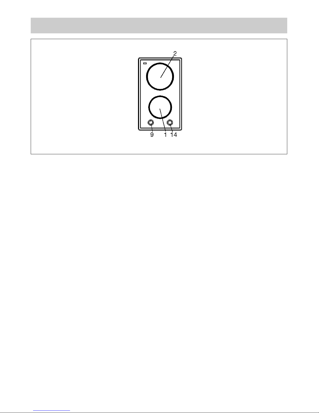
1 Radiant electric heating element Ø 145 mm 1200 W (even if “Hi-light”)
2 Radiant electric heating element Ø 180 mm 1700 W (even if “Hi-light”)
9 Switch for plate n. 1 front
14 Switch for plate n. 2 bach
DESCRIPTION OF THE CERAMIC COOKTOP
1) CERAMIC COOKTOP
The hot plates are equipped with 2 radiant heating
elements with different powers and diameters.
Cooking zones are aesily identifiables thanks to the
circles (see illustration in description) on the top;
relative powers are listed in the scheme n. 1.
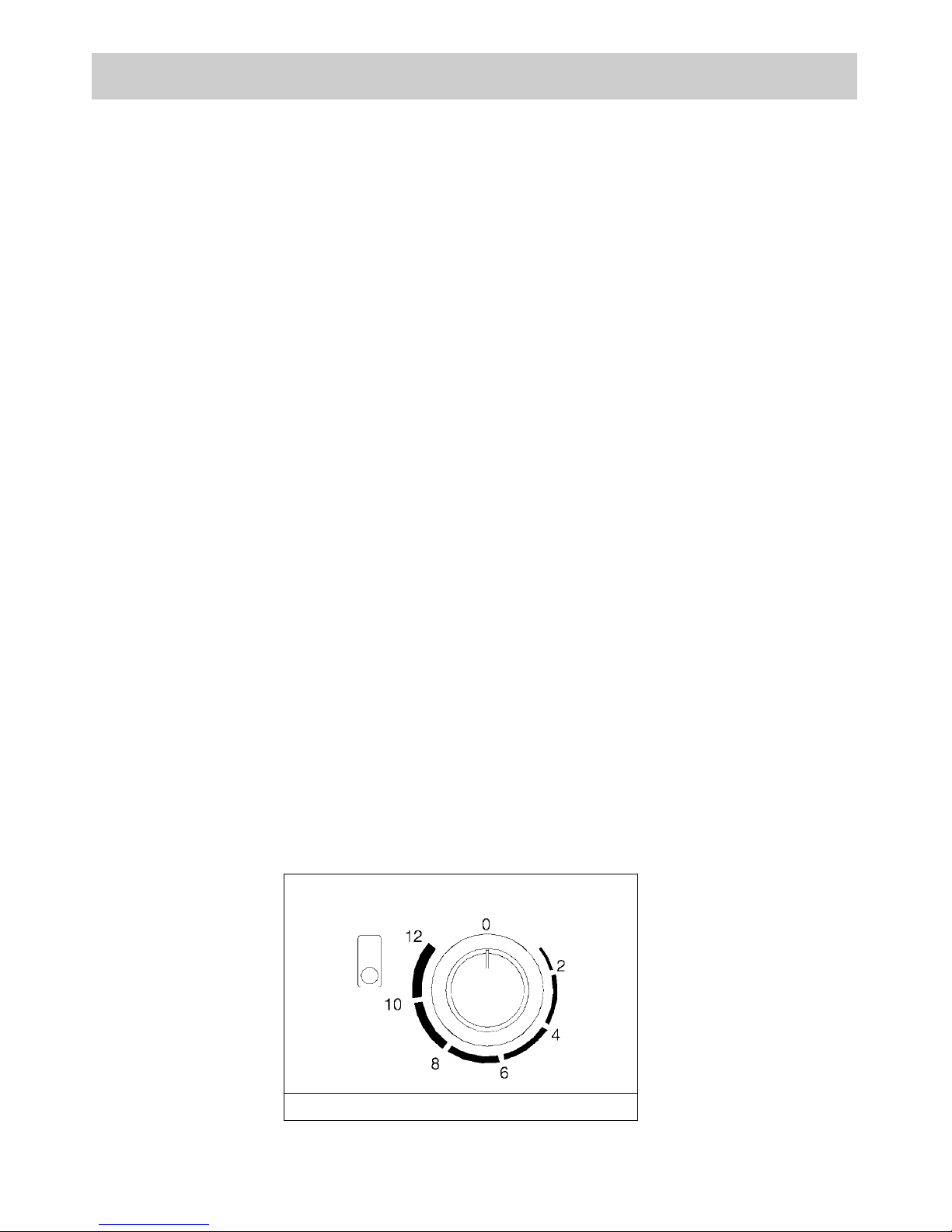
On the frontal panel, close to each knob, has been
silk-screened a scheme where is indicated to which
cooking zone the knob refers (fig. 1).
In some particular models the scheme annexes a
light indicator that turns on when the cooking zone
temperature is above 60° C (fig. 1).
The indicator will turn off only when the temperature
of the cooking zone will be below the value: this is
the reason why we call it residual heat indicator.
Some other models they have only one indicator
(see description paragraph).
Connection of electric heating elements
Hea ting eleme nts are contr olled by ener gy
regulators with 12 positions that permit to obtain a
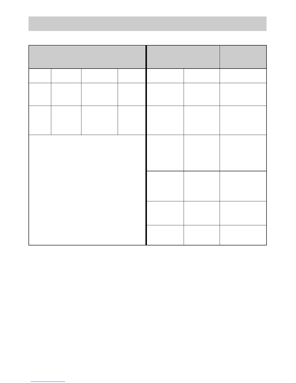
big range of different temperatures. In Scheme 1,
by way of information, we give instructions to obtain
different cooking levels.
To connect the heating elements is necessary to
turn clockwise or anticlockwise the relative knob.
How to use the cooking zones
Heating takes place only in the inside part of the
circles drawn on the special glass. The circles have
to be wholly covered by the pots.
3
USE
FIG. 1
4
USE
SCHEME 1
1 145 Radiant 1200 1 1
(even if
“Hi-light”)
2 180 Radiant 1700 2 1 - 4
(even if
“Hi-light”)
Zone Diameter Heating Power
Commutators
Energy
n° in mm. elements W regulators
6 12
5 10 - 12
To hea t fo o ds,
thaw deep-frozen
foo ds, to cook
fruits and pulses.
To melt but ter,
cho colate and
else.
To fry with oil and
to hea t big
quantities of water.
To cook ro ast of
meat, fish; to cook
steaks and eggs.
To cook meat, fish,
pulses with sauce.
To hea t sm a ll
quantities of liquid
and to keep dishes
warm.
Power and dimensions of the
cooking zones
Position for regulation
of the knobs
Possible
cookings
4 8 - 10
3 4 - 8
 Loading...