

Tridonic SLE G6 Technical Manual
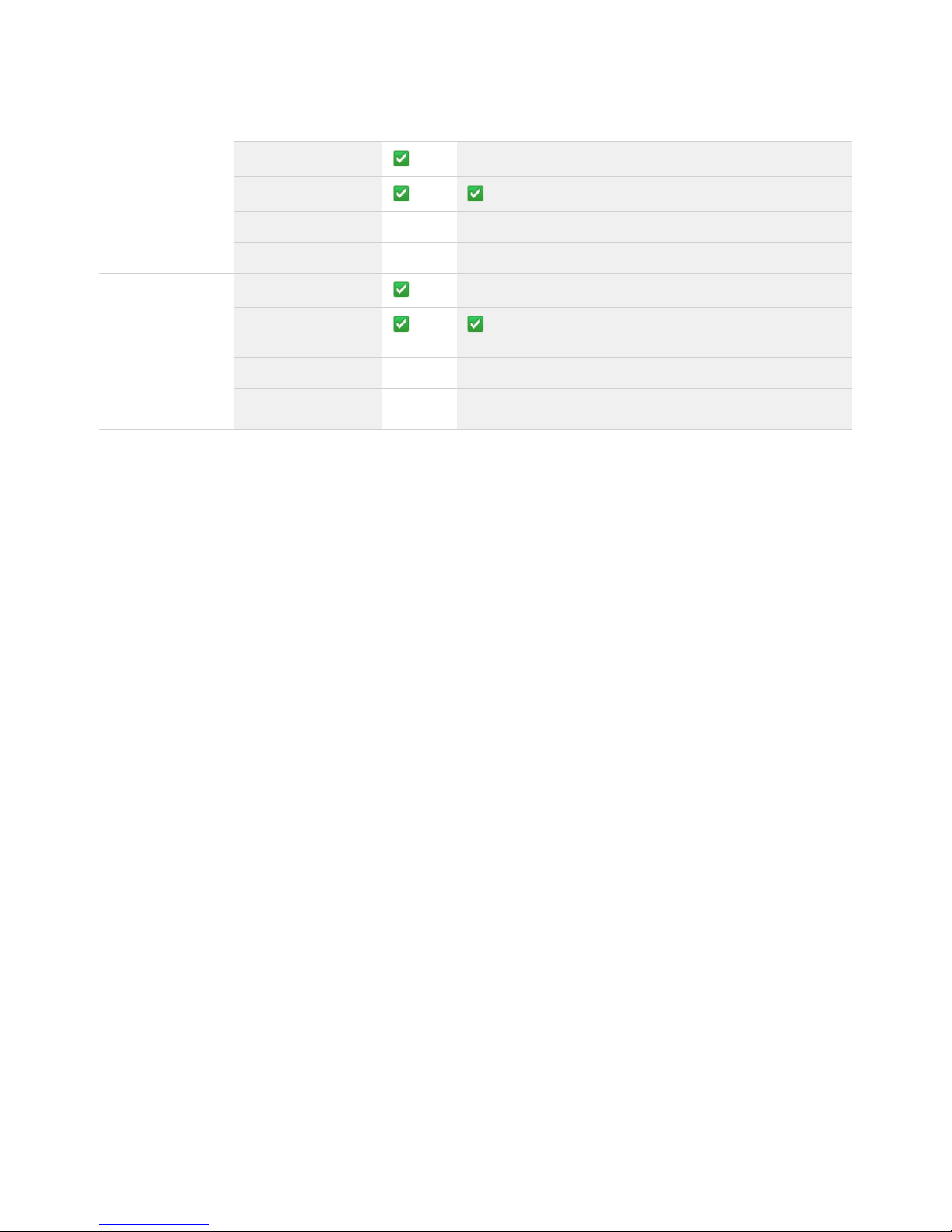
Ø13,5*
□18,8
Ø13,5*
□18,8
Ø3,3 (2x)
Ø50
Ø19
Ø17,5*
35
Ø50
Ø23
35
Ø3,3 (2x)
Ø50
Ø19
Ø17,5*
35
Ø3,3 (2x)
Ø50
Ø23
Ø21,5*
35
Ø50
Ø23
Ø21,5*
35
Ø3,3 (2x)
Ø50
Ø23
Ø21,5*
35
Ø3,3 (2x)
Ø8,5*
□13,4
Ø8,5*
□13,4
LED Module
Module SLE G6
Technical Design-In Guide

Technical Design-in Guide SLE G6 | 12-2018 | 2.1 | en
Table of Contents
c
2 / 59
...
1. Introduction 3
2. System overview 5
2.1. Complete system solution . . . . . . . . . . . . . . . . . . . . . . . . . . . . . . . . . . . . . . . . . . . . . . . . . . . . . . . . . . . . . . . . . . . . . . . . . . . . . . . . . . . . . . . . . . . . . . . . . 5
2.2. Zhaga . . . . . . . . . . . . . . . . . . . . . . . . . . . . . . . . . . . . . . . . . . . . . . . . . . . . . . . . . . . . . . . . . . . . . . . . . . . . . . . . . . . . . . . . . . . . . . . . . . . . . . . . . . . . . . . . . . . . 5
2.3. Module variants . . . . . . . . . . . . . . . . . . . . . . . . . . . . . . . . . . . . . . . . . . . . . . . . . . . . . . . . . . . . . . . . . . . . . . . . . . . . . . . . . . . . . . . . . . . . . . . . . . . . . . . . . . 6
2.4. Accessories . . . . . . . . . . . . . . . . . . . . . . . . . . . . . . . . . . . . . . . . . . . . . . . . . . . . . . . . . . . . . . . . . . . . . . . . . . . . . . . . . . . . . . . . . . . . . . . . . . . . . . . . . . . . . . 8
2.5. Compatibility between LED module and LED Driver . . . . . . . . . . . . . . . . . . . . . . . . . . . . . . . . . . . . . . . . . . . . . . . . . . . . . . . . . . . . . . . . . . . . . . . 11
2.6. Standards and directives . . . . . . . . . . . . . . . . . . . . . . . . . . . . . . . . . . . . . . . . . . . . . . . . . . . . . . . . . . . . . . . . . . . . . . . . . . . . . . . . . . . . . . . . . . . . . . . . . 14
3. Mechanical aspects 16
3.1. Installation . . . . . . . . . . . . . . . . . . . . . . . . . . . . . . . . . . . . . . . . . . . . . . . . . . . . . . . . . . . . . . . . . . . . . . . . . . . . . . . . . . . . . . . . . . . . . . . . . . . . . . . . . . . . . . . 16
4. Electrical safety 25
4.1. Electrical connections . . . . . . . . . . . . . . . . . . . . . . . . . . . . . . . . . . . . . . . . . . . . . . . . . . . . . . . . . . . . . . . . . . . . . . . . . . . . . . . . . . . . . . . . . . . . . . . . . . . . 25
4.2. Wiring diagrams . . . . . . . . . . . . . . . . . . . . . . . . . . . . . . . . . . . . . . . . . . . . . . . . . . . . . . . . . . . . . . . . . . . . . . . . . . . . . . . . . . . . . . . . . . . . . . . . . . . . . . . . . 28
5. Optical aspects 31
5.1. Colour spectrum . . . . . . . . . . . . . . . . . . . . . . . . . . . . . . . . . . . . . . . . . . . . . . . . . . . . . . . . . . . . . . . . . . . . . . . . . . . . . . . . . . . . . . . . . . . . . . . . . . . . . . . . . 31
5.2. CRI, Ra and Ri - different colour rendering values . . . . . . . . . . . . . . . . . . . . . . . . . . . . . . . . . . . . . . . . . . . . . . . . . . . . . . . . . . . . . . . . . . . . . . . . . . 31
5.3. SDCM . . . . . . . . . . . . . . . . . . . . . . . . . . . . . . . . . . . . . . . . . . . . . . . . . . . . . . . . . . . . . . . . . . . . . . . . . . . . . . . . . . . . . . . . . . . . . . . . . . . . . . . . . . . . . . . . . . . 32
5.4. Binning . . . . . . . . . . . . . . . . . . . . . . . . . . . . . . . . . . . . . . . . . . . . . . . . . . . . . . . . . . . . . . . . . . . . . . . . . . . . . . . . . . . . . . . . . . . . . . . . . . . . . . . . . . . . . . . . . 33
5.5. Secondary Optics . . . . . . . . . . . . . . . . . . . . . . . . . . . . . . . . . . . . . . . . . . . . . . . . . . . . . . . . . . . . . . . . . . . . . . . . . . . . . . . . . . . . . . . . . . . . . . . . . . . . . . . . 33
5.6. Coordinates and tolerances (to CIE 1931) . . . . . . . . . . . . . . . . . . . . . . . . . . . . . . . . . . . . . . . . . . . . . . . . . . . . . . . . . . . . . . . . . . . . . . . . . . . . . . . . . 33
5.7. Eye safety . . . . . . . . . . . . . . . . . . . . . . . . . . . . . . . . . . . . . . . . . . . . . . . . . . . . . . . . . . . . . . . . . . . . . . . . . . . . . . . . . . . . . . . . . . . . . . . . . . . . . . . . . . . . . . . 34
5.8. Reflector design and beam characteristics . . . . . . . . . . . . . . . . . . . . . . . . . . . . . . . . . . . . . . . . . . . . . . . . . . . . . . . . . . . . . . . . . . . . . . . . . . . . . . . . 36
6. Thermal aspects 39
6.1. Decrease of luminous flux . . . . . . . . . . . . . . . . . . . . . . . . . . . . . . . . . . . . . . . . . . . . . . . . . . . . . . . . . . . . . . . . . . . . . . . . . . . . . . . . . . . . . . . . . . . . . . . . 39
6.2. Passive and active cooling . . . . . . . . . . . . . . . . . . . . . . . . . . . . . . . . . . . . . . . . . . . . . . . . . . . . . . . . . . . . . . . . . . . . . . . . . . . . . . . . . . . . . . . . . . . . . . . 44
6.3. Fan connection and temperature measurement . . . . . . . . . . . . . . . . . . . . . . . . . . . . . . . . . . . . . . . . . . . . . . . . . . . . . . . . . . . . . . . . . . . . . . . . . . . 45
7. Ordering information and sources 48
7.1. Article numbers . . . . . . . . . . . . . . . . . . . . . . . . . . . . . . . . . . . . . . . . . . . . . . . . . . . . . . . . . . . . . . . . . . . . . . . . . . . . . . . . . . . . . . . . . . . . . . . . . . . . . . . . . 48
7.2. Product application matrix . . . . . . . . . . . . . . . . . . . . . . . . . . . . . . . . . . . . . . . . . . . . . . . . . . . . . . . . . . . . . . . . . . . . . . . . . . . . . . . . . . . . . . . . . . . . . . . 55
7.3. Partners . . . . . . . . . . . . . . . . . . . . . . . . . . . . . . . . . . . . . . . . . . . . . . . . . . . . . . . . . . . . . . . . . . . . . . . . . . . . . . . . . . . . . . . . . . . . . . . . . . . . . . . . . . . . . . . . 56
Technical Design-in Guide SLE G6 | 12-2018 | 2.1 | en
Introduction
c
3 / 59
This Design-in Guide covers the SLE G6 Spotlight system from Tridonic.
The SLE G6 provides energy efficient lighting solutions with high quality light for retail, catering and other spotlight and downlight
applications.
The system consists of chip-on-board module and mount, chip-on-board module with pre-tinned wires or chip-on-board module
without cable in four versions:
The Design-in guide provides all the information needed to build a luminaire with the SLE G6 Spotlight system and adapt it to the
desired needs.
This includes:
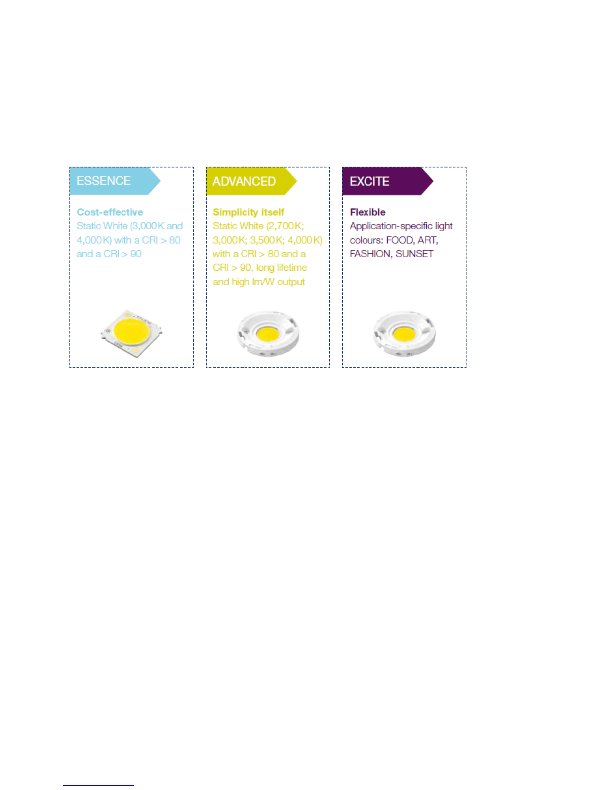
Standard version with different lumen packages and different light colours (2,700 K, 3,000 K, 3,500 K, 4,000 K)_
Three special versions that are optimised for specific applications:_
SLE FOOD:
LED modules specifically for FOOD applications display foods in the very best light – white elements remain white,
colours are more true-to-life and are perceived more intensively. Stronger brown tones for example make baked goods
appear more crispy, and the red of meats is emphasised to greater effect.
_
SLE ART:
This new LED module offers the high quality of light that is needed for displaying high value exhibits. Unique Tridonic
full spectrum technology provides excellent colour rendering. The average value for all the products in the SLE ART
series is CRI 98, a truly impressive figure. And you can also rely on outstanding colour consistency (MacAdam 2) for
your applications.
_
SLE FASHION:
The modern FASHION LED light is ideal for the sparkling display of fashion. The technology conceals several years of
intensive research targeted specifically for lighting in the retail sector. SLE FASHION generates brilliant colours with
pleasant warm tones and high saturation, and completely without UV light, as well as intensive and friendly white
tones thanks to the specific blue light component, for the display of goods in perfect, colour-true light.
_
Dimensioning of the heat sink and reflector_
Selection of compatible LED Drivers_

Technical Design-in Guide SLE G6 | 12-2018 | 2.1 | en
Introduction
c
4 / 59
...
Designing the luminaire with respect to thermal and mechanical needs_

Technical Design-in Guide SLE G6 | 12-2018 | 2.1 | en
System Overview
c
5 / 59
2.1. Complete system solution
The use of LEDs in general lighting has many advantages: LEDs are versatile in their application, highly energy efficient and virtually
maintenance-free. With the Engine SLE G6 you get a complete system solution for spot and downlights, consisting of perfectly
matched components: LED module and LED Driver.
2.2. Zhaga
Zhaga is a consortium, initiated in 2010, which takes care of the needs of LED lighting and its standardisation. It is active worldwide
and has more than 200 member companies (as of 2012).
The aim of the Zhaga consortium is to ensure interchangeability and compatibility of LED luminaires between different manufacturers.
To this end, Zhaga defines standards for the interfaces of the various lighting fixtures and holders. This includes the physical
dimensions of the lamp base, as well as the photometric, electrical and thermal behaviour of LED luminaires. These standardizing
measures help to make products comparable, a step that both the manufacturing industry and the consumers benefit from.
The Zhaga logo verifies compatibility with Zhaga standards. Only certified devices are allowed to bear this logo.
The SLE G6 modules meet the mechanical requirements of the Zhaga guidelines from book number 3. Products that meet the Zhaga
standards in physical, electrical and thermal points are listed on the website of Zhaga: www.zhagastandard.org
I NOTICE
All information in this guide has been created with great care. Errors, additions and omissions excepted. For any resulting damage
Tridonic accepts no liability. The latest version of this guide can be found at or at your sales partner.led.tridonic.com
Technical Design-in Guide SLE G6 | 12-2018 | 2.1 | en
System Overview
c
6 / 59
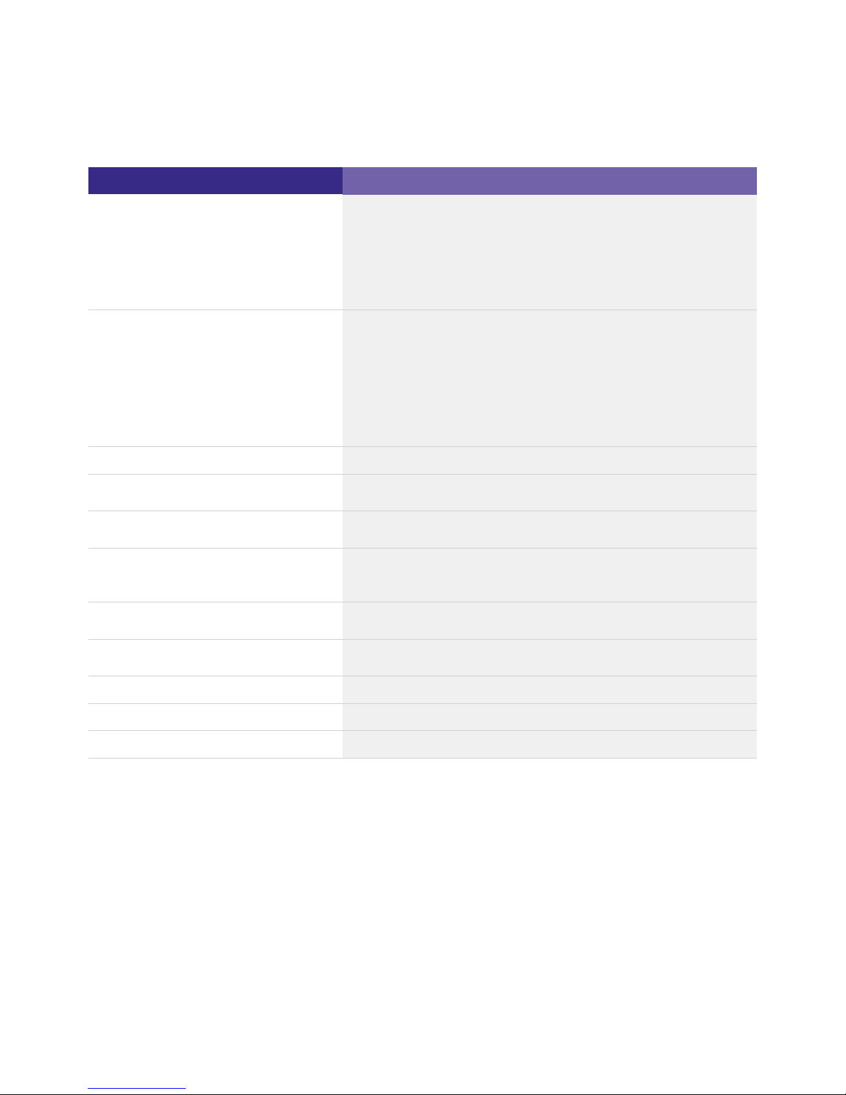
2.3. Module variants
Module name
Housing Thermal interface material Connection cable
with affix "H",
e.g. SLE G6 19mm 5000lm 830 H ADV
with affix "H" and "T",
e.g. SLE G6 19mm 5000lm 830 H ADV T
with affix "C",
e.g. SLE G6 19mm 5000lm 830 C ADV
with affix "R",
e.g. SLE G6 19mm 5000lm 830 R ADV
...
I NOTICE
The SLE G6 series comprises different variants of modules:
with housing_
with housing and thermal interface material_
without housing, with or without connection cable_
Modules without housing or connection cable have a certain affix in their name:
Modules without housing have the affix "H" in their name_
Modules with housing and have the affix "H" and "T" in their namethermal interface material _
Modules with have the affix "C" in their nameconnection cable _
Modules without connection cable have the affix "R" in their name_
Modules without housing or connection cable have a certain affix in their name:
Modules without housing have the affix "PURE" in their name_
Modules without connection cable have the affix "W/O-C" in their name_
Abbreviations:
H ... housing; T ... thermal interface material; C ... cable; R ... raw_
The following variants are available:
Technical Design-in Guide SLE G6 | 12-2018 | 2.1 | en
System Overview
c
7 / 59
The system Engine STARK SLE GEN4 is available in different variants:
SLE G6 ADV
Main qualities
Simplicity itself:
Available variants Available in 4 variants:
Light Emitting Surface ( LES) 10 mm, 15 mm, 17 mm, 19 mm, 23 mm
Colour temperature 2,700 K, 3,000 K, 3,500 K, 4,000 K
Luminous flux
(1)
up to 9,960 lm
Colour rendering / colour tolerance CRI 80, CRI 90
MacAdam 3 SDCM
System efficiency
(1)
up to 154 lm/W
Module efficiency up to 180 lm/W
Energy efficiency class up to A++
Life time
(2)
> 60,000 h
Warranty 5 years
(1)
Values at t =65°C, all values apply to tp rated
p
relating to L70/B50
(2)
2.3.1. Type code for modules
The following type code is used to identify the modules:
Static White with CRI > 80 and CRI > 90_
long life-time_
high lm/W output_
with housing, without thermal interface material_
with housing, with thermal interface material_
without housing, without thermal interface material_
without housing, with thermal interface material_

Technical Design-in Guide SLE G6 | 12-2018 | 2.1 | en
System Overview
c
8 / 59
Type code for modules for SLE G6 19mm 5000lm 830 H ADV T for example
Reference
SLE G6 19mm 5000lm 830 H ADV T
Meaning
Form: Spotlight
Engine
Size Type: Luminous flux at nominal
current
CRI 80
3000K
with
housing
ADV with thermal interface
material (TIM)
2.4. Accessories
2.4.1. LED Drivers
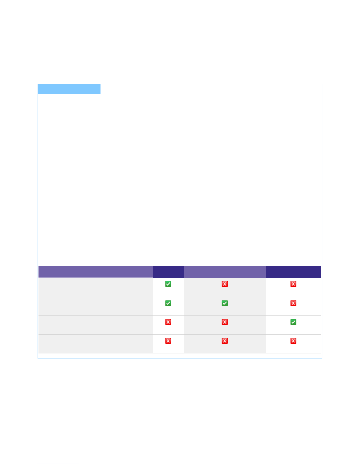
LED Drivers are available in different variants:
PRE EXC
Dimming
Amplitude
Dimming range 100 to 1 % 100 to >= 15 %
DALI V2-DT6
DSI
switchDIM
corridorFUNCTION V2
ready2mains
DC operation supporting EN 50172
DC level fixed
DC level adjustable
Current adjustment Adjustable
Via resistor or plug
I NOTICE
The exact minimum value depends on the used device and the
load.
For certain devices, the minimum value may be higher_
When operating with lower load, the minimum value is
generally higher
_
More information can be found in the data sheet of the device.
Technical Design-in Guide SLE G6 | 12-2018 | 2.1 | en
System Overview
c
9 / 59
Via DALI V2-DT6
ready2mains
current resolution 1 mA 1 mA
current tolerances ± 3-10 % see data sheet
Functions &
Performances
CLO function
Intelligent temperature
guard
Standby losses <0.2 W
Rated supply voltage 220-240 V 220-240 V
2.4.2. Possible combinations
Possible combinations of LED Drivers and LED modules can be found in the LED system matrix:
www.tridonic.com/com/en/lamp-matrix.asp
Some typical combinations are listed here:
SLE G6 10mm: Operating current: 350mA
SLE G6 15mm: Operating current: 500mA
SLE G6 17mm: Operating current: 900mA
SLE G6 19mm: Operating current: 1050mA
Dimmable: LCA 25W 350-1050mA one4all C PRE (28000665)_
Dimmable/Fixed Output: LC 17W 250-700mA flexC SC EXC (28000705)_
Fixed Output: LC 15W 350mA fixC SC ADV (87500448)_
Fixed Output: LC 15W 350mA fixC C SNC (87500565)_
Dimmable: LCA 25W 350-1050mA one4all C PRE (28000665)_
Dimmable/Fixed Output: LC 25W 350-1050mA flexC SC EXC (28000706)_
Fixed Output: LC 20W 500mA fixC SC ADV (87500449)_
Fixed Output: LC 20W 500mA fixC C SNC (87500566)_
Dimmable: LCA 45W 500-1400mA one4all SC PRE (28000676)_
Fixed Output: LC 40W 900mA fixC SC ADV (87500344)_
Fixed Output: LC 40W 900mA fixC C SNC (87500560)_
Dimmable: LCAI 55W 900-1750mA ECO C (28000128)_
Fixed Output: LC 47W 1050mA fixC SC ADV (87500451)_
Fixed Output: LC 45W 1050mA fixC C SNC (87500564)_

Technical Design-in Guide SLE G6 | 12-2018 | 2.1 | en
System Overview
c
10 / 59
SLE G6 23mm: Operating current: 1400mA
Type codes for LED Drivers
The following type code is used to identify LED Drivers:
Type code for LED Drivers LCA 45W 500-1400mA one4all SR PRE
Reference
LCAI 45W 500-1400mA one4all SR / C / SC PRE
Meaning
Dimmable LED
Driver
Power Output current
range
Interface Housing form:
SR: Strain Relief, C: Compact, SC: Stretch
Compact
Type
The exact type designation of the LED Driver can be found on the label of the LED Driver.
...
Dimmable: LCAI 55W 900-1750mA ECO C (28000128)_
Fixed Output: LC 60W 1400mA fixC C SNC (87500570)_
Technical Design-in Guide SLE G6 | 12-2018 | 2.1 | en
System Overview
c
11 / 59
2.5. Compatibility between LED module and LED Driver
There are two stages involved in the check for compatibility between the LED module and the LED Driver.
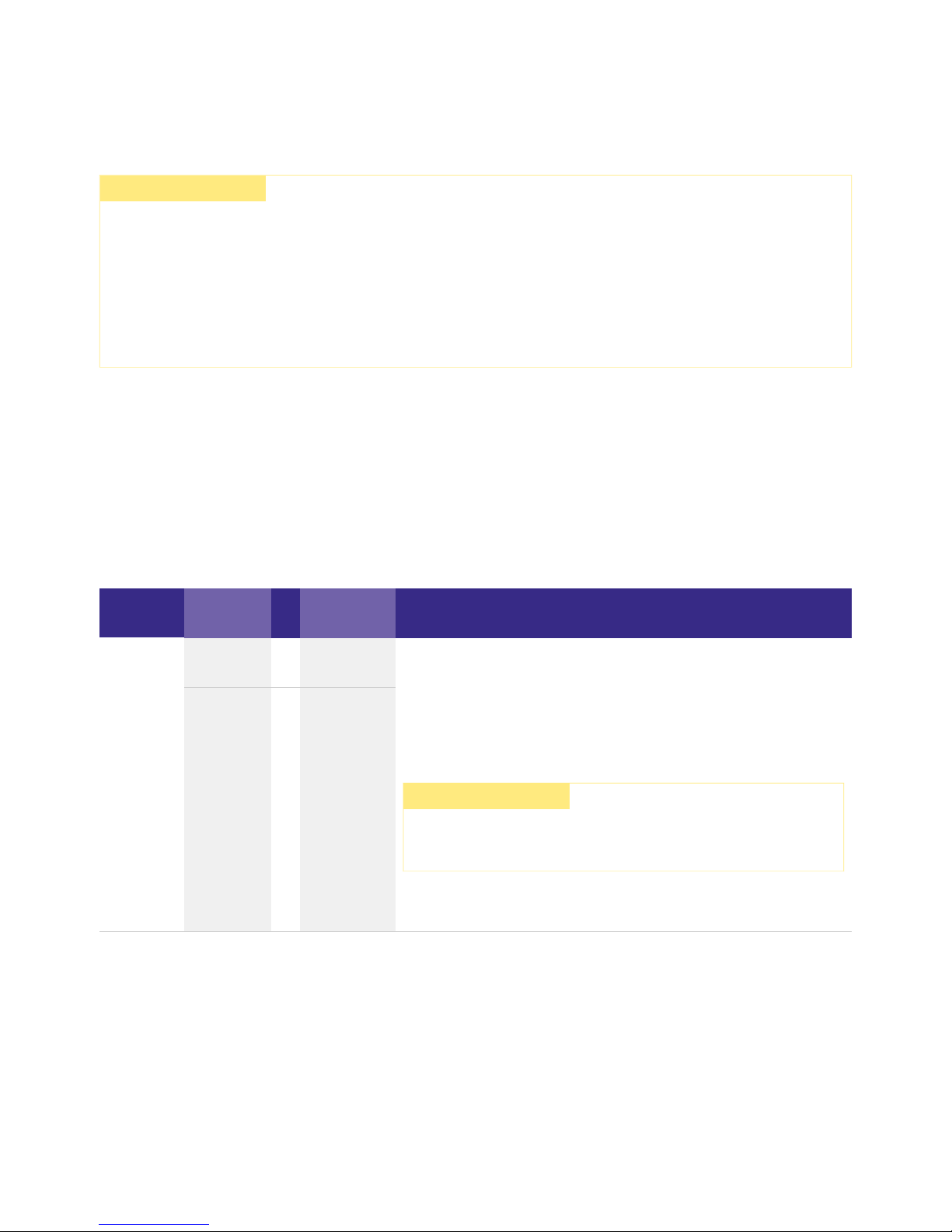
2.5.1. Comparison of data sheet values with a 5-point guideline
Different values for the two devices need to be considered when comparing the data sheets. The following table shows which values
are involved and which requirements they must meet.
Comparison
of…
Value in
LED module
Value in LED
Driver Detailed procedure
(1) Current
I
max
= Output
current
continue...
Max. DC
forward
current
>= Output
current +
tolerances
...
½ CAUTION!
LED modules SLE G6 are basic isolated against ground up to 75 V (for LES10, LES15 and LES17: 50 V) and can be mounted directly
on earthed metal parts of the luminaire.
If the max. output voltage of the LED Driver (also against earth) is above 75 V (for LES10, LES15 and LES17: 50 V), an additional
isolation between LED module and heat sink is required (for example by isolated thermal pads) or by a suitable luminaire
construction.
At voltages > 60 V an additional protection against direct touch (test finger) to the light emitting side of the module has to be
guaranteed. This is typically achieved by means of a non removable light distributor over the module.
The requirements for operating together can be checked by comparing the data sheets_
Subsequent practical tests can ensure that there are no unexpected problems during actual operation_
Determine forward current of LED module_
Check whether LED Driver can be operated with the same output
current
_
Check whether max. DC forward current of LED module is greater than
or equal to output current of LED Driver (including tolerances)
_
½ CAUTION!
The max. DC forward current can be temperature dependent!
Refer to the derating curve of the LED module data sheet.

Technical Design-in Guide SLE G6 | 12-2018 | 2.1 | en
System Overview
c
12 / 59
Comparison
of…
Value in LED
module
Value in LED
Driver Detailed procedure
(2) Voltage
Min. forward
voltage
> Min. output
voltage
Max. forward
voltage
< Max. output
voltage
Min. forward
voltage
@ min. dim
level
> Min. output
voltage
(3) LF current
ripple
Max.
permissible
LF current
ripple
>= Output LF
current ripple
(<120 Hz)
(4) Max. peak
current
Max.
permissible
peak current
> Max. output
current peak
(5) Power
(pertinent for
multi channel
LED Driver)
Min. power
consumption
> Min. output
power
Max. power
consumption
< Max. output
power
Check whether voltage range of LED module is completely within
the voltage range of LED Driver
_
½ CAUTION!
!The forward voltage is temperature dependent
Refer to the Vf/t diagram in the data sheet.p
I NOTICE
To ensure full dimming performance the forward voltage of the LED
module at min. dim level must be greater than or equal to the min.
output voltage of the driver.
Determine the forward voltage of the LED module at lowest dim
level
_
In case there is no data available for the LED module at lowest dim
level: take the min. forward voltage minus 20 % as an
approximation
_
Check whether the forward voltage of the LED module is greater
than or equal to the min. output voltage of the driver
_
Check whether max. permissible LF current ripple of LED module is
greater than or equal to output LF current ripple of LED Driver
_
Check whether max. permissible peak current of LED module is
greater than max. output current peak of LED Driver
_
Check whether power range of LED module is completely within
output power range of LED Driver
_

Technical Design-in Guide SLE G6 | 12-2018 | 2.1 | en
System Overview
c
13 / 59
2.5.2. Practical tests
The following aspects must be checked:
Technical aspects
Visual aspects
When conducting the tests the following conditions must be considered:
Conditions
½ CAUTION!
Following the comparison of the data sheet values a practical test is required. Only a practical test can ensure that the system
LED Driver components (luminaire, , LED module, wiring) are coordinated and working properly.
Transient behaviour_
Colour shift_
Connection during operation_
Parasitic capacitance_
Flickering_
Stroboscopic effect (video applications)_
Dimming behaviour_
Colour change/stability_
Luminous flux_
All tolerances_
Entire temperature range_
Different output voltage ranges (incl. no load)_
Entire dimming range_
Short circuit_
I HINWEIS
If the values are slightly over or under the specified threshold values or if there are any other concerns or questions please contact
Technical Support:
techservice@tridonic.com
Technical Design-in Guide SLE G6 | 12-2018 | 2.1 | en
System Overview
c
14 / 59
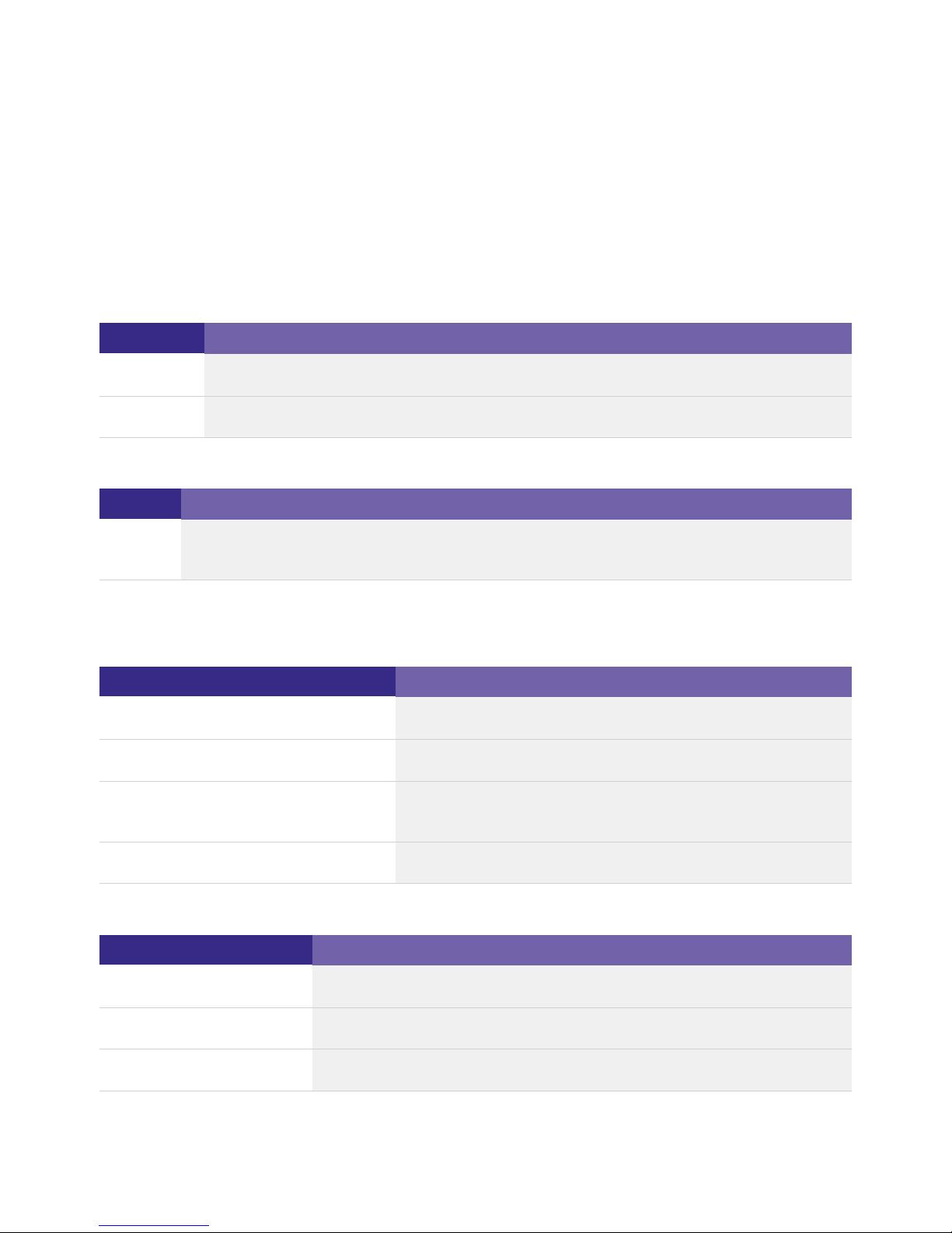
2.6. Standards and directives
2.6.1. Standards and directives for modules
The following standards and directives were taken into consideration in designing and manufacturing the modules:
CE
Name
Description
2006/95/EG
Low-voltage directive: Directive relating to electrical equipment for use within certain voltage limits
2004/108/EG EMC directive: Directive relating to electromagnetic compatibility
RoHS
Name
Description
2002/95/EC
RoHS directive: Directive on the restriction of the use of certain hazardous substances in electrical and electronic
(1)
equipment
(1)
RoHS: Restriction of (the use of certain) hazardous substances
Safety
Name
Description
DIN IEC 62031:2008
Safety requirements for LED modules
EN 60598-1:2008 und A11:2009 General requirements and tests for luminaires
EN 60598-2-2:1996 und A1:1997 Luminaires - Part 2. Special requirements;
Main section 2: Recessed luminaires
EN 62471:2008 Photo-biological safety of lamps and lamp systems
Safety and performance
Name
Description
EN 61347-1:2009
General and safety requirements
EN 61347-2-13:2007 Special requirements for dc and ac powered electronic operating equipment for LED modules
EN 62384:2007 IEC 62384 A1:2009 Operational requirements
Technical Design-in Guide SLE G6 | 12-2018 | 2.1 | en
System Overview
c
15 / 59
Energy labelling
Name
Description
EU Regulation No: 874/2012
"Energy labelling of electrical lamps and luminaires"
2.6.2. Standards and directives for LED Drivers
The following standards and directives were taken into consideration in designing and manufacturing the LED Drivers:
EMI
Name
Description
EN 55015 2008
Limit values measurement methods for radio interference properties of electrical lighting equipment
and similar electrical devices
EN 61000-3-2:2005 A1: 2008
und A2:2009
Limit values for harmonic currents (equipment input current < 16 A per conductor)
EN 61000-3-3:2005 Limit values for voltage fluctuations and flicker in low-voltage systems for equipment with an input
current < 16 A per conductor that are not
subject to any special connection conditions
EN 61547:2001 EMC requirements
(1)
(1)
EMC: Electromagnetic compatibility
Safety
Name
Description
EN 50172 2005
Safety lighting systems
DALI
Name
Description
IEC 62386-101:2009
General requirements, system
IEC 62386-102:2009 General requirements, controller
IEC 62386-207:2009 Special requirements, controller; LED modules
...
Technical Design-in Guide SLE G6 | 12-2018 | 2.1 | en
Mechanical Aspects
c
16 / 59
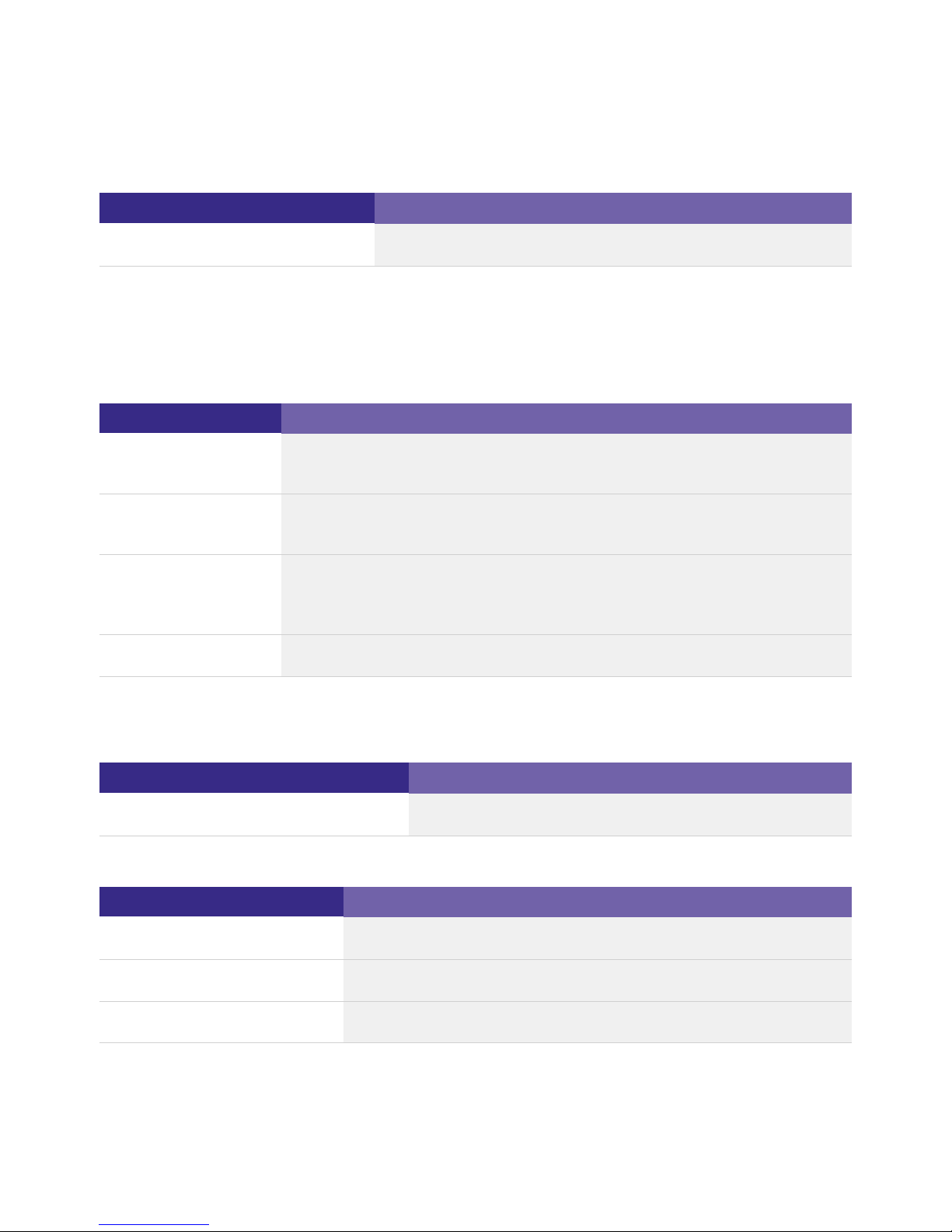
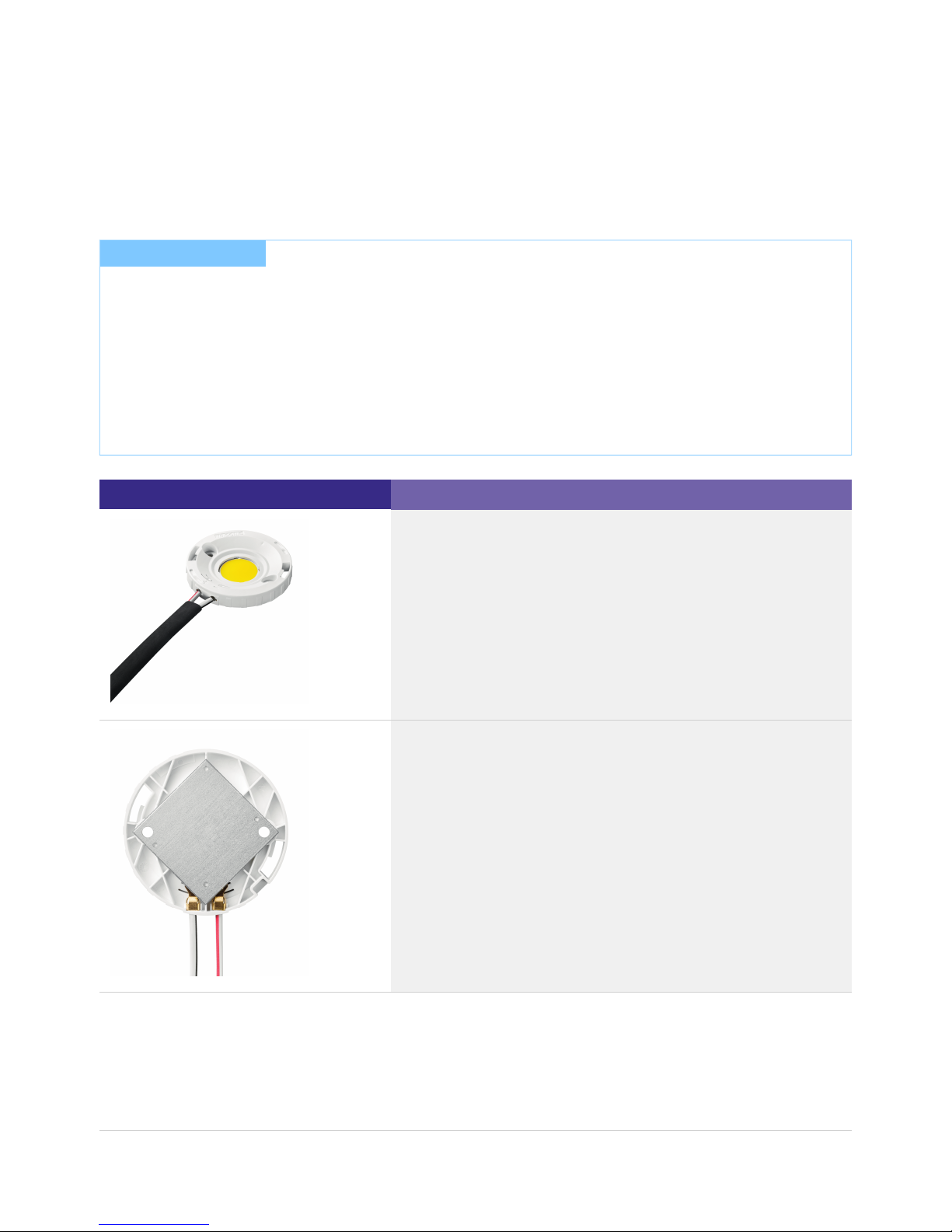
3.1. Installation
The guideline for installation can be taken from the ESD documentThe SLE G6 modules were tested with severity level 4. .
Image
Description
Integrated terminal for a time-saving assembly
Back of the module for thermal connection to the heat sink
I NOTICE
EOS/ESD safety guidelines
The device/module contains components that are sensitive to electrostatic discharge and may only be installed in the factory and
on site if appropriate EOS/ESD protection measures have been taken. No special measures need be taken for devices/modules with
enclosed casings (contact with the pc board not possible), just normal installation practice.
Please note the requirements set out in the document EOS/ESD guidelines (Guideline_EOS_ESD.pdf) at:
http://www.tridonic.com/com/de/download/technical/Richtlinie_EOS_ESD_de.pdf_
http://www.tridonic.com/com/en/technical-docs.asp_

Technical Design-in Guide SLE G6 | 12-2018 | 2.1 | en
Mechanical Aspects
c
17 / 59
Version without housing for individual integration in the light
3.1.1. Notes on installation
Depending on the installation situation for the LED Driver and the modules, the following requirements must be met:
Protection measures against damage
Mechanical stress
LED modules contain electronic components that are sensitive to mechanical stress. Such stress should be kept to an absolute
minimum. In particular the following mechanical stresses should be avoided as these may cause irreversible damage:
½ CAUTION!
LED module and the associated housings are crimped together by sleeves.
Trying to separate LED module and housing will destroy the LED module!
All warranty and guarantee claims are void if LED module and housing are separated or if the LED module is altered, modified or
disassembled in any form.
Sufficient distance to active conducting materials_
Sufficient strain relief when the LED Driver cover is closed_
Sufficient cooling of the modules (the max. temperature at the tc point must not be exceeded)_
Unrestricted exit of light from the modules_
The module's push-in terminals allow easy wiring. They can be released via the trigger_
Pressure_
Drilling_
Milling_
Breaking_
Sawing_
and similar mechanical processing._
Technical Design-in Guide SLE G6 | 12-2018 | 2.1 | en
Mechanical Aspects
c
18 / 59
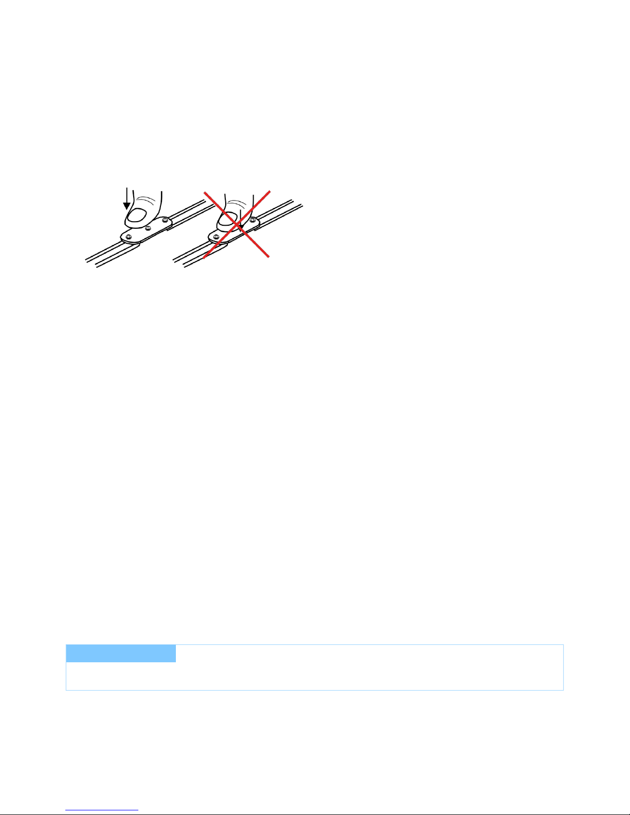
Compressive stresses
The components of the LED modules (circuit boards, glob-top, lenses, electronic components etc.) are sensitive to compressive
stresses. The components must not be exposed to compressive stresses.
Chemical compatibility
LED modules can be damaged by other materials, if these materials have certain chemical properties. The cause for these damages
are different gaseous compounds, which penetrate into the encapsulant of the LED and thereby attack the encapsulant, the colour
conversion phosphor or the LED chips and can affect the electrical contacts or the substrate.
Application areas for chemical substances
The following are known areas in which chemical substances are used:
The following materials must be checked for their safety:
Putting together a "safe list" is not possible due to the complexity of the topic. The following table lists possible contaminants for LED
modules, the classes of compounds and examples of possible sources.
The list shows the most commonly used materials but does not claim to be complete.
If glass or Plexiglas shields are used make sure that pressure is not exerted on the glob-top._
Only touch the LED modules at the edges
correct (left) and incorrect (right)
_
use of protective coating in applications with high relative humidity (outdoor applications),_
encapsulation of LED modules,_
cementing of LED modules,_
sealing of luminaires._
All components and auxiliaries used in the assembly of the luminaire:_
Solvents of adhesives and coatings_
Other so-called VOC ("volatile organic compounds")_
All other additional substances present in the atmosphere:_
Outgassing of adhesives, sealants and coatings_
Cleaning agents and processing aids (e.g. cutting oils and drilling coolants)_
I NOTICE
Contact your LED manufacturer for questions about the materials used and possible interactions and risks.
 Loading...