

360
4.1
4.1
30
360
4.1
4.1
30
360
4.1
360
4.1
4.1
30
360
4.1
4.1
30
360
4.1
4.1
30
270
0.4
222
24
270
0.4
180
45
tc1
tc2
t3
4,3 (4x)
270
0.4
222
24
270
0.4
180
45
tc1
tc2
t3
4,3 (4x)
270
0.4
222
24
270
0.4
180
45
tc1
tc2
t3
4,3 (4x)
270
0.4
222
24
270
0.4
180
45
270
0.4
222
24
270
0.4
180
24
270
0.4
180
45
tc1
tc2
LED Module
Engine QLE G2 PRE KIT
Technical Design-in Guide

Technical Design-in Guide Engine QLE G2 PRE KIT | 01-2019 | 1.0 | en
Table of Contents
c
2 / 64
1. Introduction 4
2. Summary of the chapters 5
2.1. System overview . . . . . . . . . . . . . . . . . . . . . . . . . . . . . . . . . . . . . . . . . . . . . . . . . . . . . . . . . . . . . . . . . . . . . . . . . . . . . . . . . . . . . . . . . . . . . . . . . . . . . . . . . . 5
2.2. Mechanical aspects . . . . . . . . . . . . . . . . . . . . . . . . . . . . . . . . . . . . . . . . . . . . . . . . . . . . . . . . . . . . . . . . . . . . . . . . . . . . . . . . . . . . . . . . . . . . . . . . . . . . . . . 5
2.3. Electrical aspects . . . . . . . . . . . . . . . . . . . . . . . . . . . . . . . . . . . . . . . . . . . . . . . . . . . . . . . . . . . . . . . . . . . . . . . . . . . . . . . . . . . . . . . . . . . . . . . . . . . . . . . . . 5
2.4. Optical aspects . . . . . . . . . . . . . . . . . . . . . . . . . . . . . . . . . . . . . . . . . . . . . . . . . . . . . . . . . . . . . . . . . . . . . . . . . . . . . . . . . . . . . . . . . . . . . . . . . . . . . . . . . . . 5
2.5. Thermal aspects . . . . . . . . . . . . . . . . . . . . . . . . . . . . . . . . . . . . . . . . . . . . . . . . . . . . . . . . . . . . . . . . . . . . . . . . . . . . . . . . . . . . . . . . . . . . . . . . . . . . . . . . . . 5
2.6. Ordering information and sources . . . . . . . . . . . . . . . . . . . . . . . . . . . . . . . . . . . . . . . . . . . . . . . . . . . . . . . . . . . . . . . . . . . . . . . . . . . . . . . . . . . . . . . . . 5
3. System Overview 6
3.1. Overview . . . . . . . . . . . . . . . . . . . . . . . . . . . . . . . . . . . . . . . . . . . . . . . . . . . . . . . . . . . . . . . . . . . . . . . . . . . . . . . . . . . . . . . . . . . . . . . . . . . . . . . . . . . . . . . . . 6
3.2. Operating functions . . . . . . . . . . . . . . . . . . . . . . . . . . . . . . . . . . . . . . . . . . . . . . . . . . . . . . . . . . . . . . . . . . . . . . . . . . . . . . . . . . . . . . . . . . . . . . . . . . . . . . 8
3.3. Type codes . . . . . . . . . . . . . . . . . . . . . . . . . . . . . . . . . . . . . . . . . . . . . . . . . . . . . . . . . . . . . . . . . . . . . . . . . . . . . . . . . . . . . . . . . . . . . . . . . . . . . . . . . . . . . . 12
3.4. Versions . . . . . . . . . . . . . . . . . . . . . . . . . . . . . . . . . . . . . . . . . . . . . . . . . . . . . . . . . . . . . . . . . . . . . . . . . . . . . . . . . . . . . . . . . . . . . . . . . . . . . . . . . . . . . . . . . 13
3.5. Standards and directives . . . . . . . . . . . . . . . . . . . . . . . . . . . . . . . . . . . . . . . . . . . . . . . . . . . . . . . . . . . . . . . . . . . . . . . . . . . . . . . . . . . . . . . . . . . . . . . . . 14
4. Mechanical aspects 16
4.1. Installation . . . . . . . . . . . . . . . . . . . . . . . . . . . . . . . . . . . . . . . . . . . . . . . . . . . . . . . . . . . . . . . . . . . . . . . . . . . . . . . . . . . . . . . . . . . . . . . . . . . . . . . . . . . . . . 16
4.2. Dimensional drawings modules . . . . . . . . . . . . . . . . . . . . . . . . . . . . . . . . . . . . . . . . . . . . . . . . . . . . . . . . . . . . . . . . . . . . . . . . . . . . . . . . . . . . . . . . . . 23
4.3. Dimensional drawings LED Driver . . . . . . . . . . . . . . . . . . . . . . . . . . . . . . . . . . . . . . . . . . . . . . . . . . . . . . . . . . . . . . . . . . . . . . . . . . . . . . . . . . . . . . . . 24
5. Electrical aspects 25
5.1. Connections on the LED Driver . . . . . . . . . . . . . . . . . . . . . . . . . . . . . . . . . . . . . . . . . . . . . . . . . . . . . . . . . . . . . . . . . . . . . . . . . . . . . . . . . . . . . . . . . . . 25
5.2. Electrical safety . . . . . . . . . . . . . . . . . . . . . . . . . . . . . . . . . . . . . . . . . . . . . . . . . . . . . . . . . . . . . . . . . . . . . . . . . . . . . . . . . . . . . . . . . . . . . . . . . . . . . . . . . 26
5.3. Electrical safety and connection . . . . . . . . . . . . . . . . . . . . . . . . . . . . . . . . . . . . . . . . . . . . . . . . . . . . . . . . . . . . . . . . . . . . . . . . . . . . . . . . . . . . . . . . . . 28
5.4. Electrical connections . . . . . . . . . . . . . . . . . . . . . . . . . . . . . . . . . . . . . . . . . . . . . . . . . . . . . . . . . . . . . . . . . . . . . . . . . . . . . . . . . . . . . . . . . . . . . . . . . . . 29
5.5. Wiring diagrams . . . . . . . . . . . . . . . . . . . . . . . . . . . . . . . . . . . . . . . . . . . . . . . . . . . . . . . . . . . . . . . . . . . . . . . . . . . . . . . . . . . . . . . . . . . . . . . . . . . . . . . . . 30
6. Optical Aspects 33
6.1. Colour spectrum . . . . . . . . . . . . . . . . . . . . . . . . . . . . . . . . . . . . . . . . . . . . . . . . . . . . . . . . . . . . . . . . . . . . . . . . . . . . . . . . . . . . . . . . . . . . . . . . . . . . . . . . . 33
6.2. Coordinates and tolerances . . . . . . . . . . . . . . . . . . . . . . . . . . . . . . . . . . . . . . . . . . . . . . . . . . . . . . . . . . . . . . . . . . . . . . . . . . . . . . . . . . . . . . . . . . . . . . 34
6.3. CRI, Ra and Ri - different colour rendering values . . . . . . . . . . . . . . . . . . . . . . . . . . . . . . . . . . . . . . . . . . . . . . . . . . . . . . . . . . . . . . . . . . . . . . . . . 34
6.4. SDCM . . . . . . . . . . . . . . . . . . . . . . . . . . . . . . . . . . . . . . . . . . . . . . . . . . . . . . . . . . . . . . . . . . . . . . . . . . . . . . . . . . . . . . . . . . . . . . . . . . . . . . . . . . . . . . . . . . . 36
6.5. Binning . . . . . . . . . . . . . . . . . . . . . . . . . . . . . . . . . . . . . . . . . . . . . . . . . . . . . . . . . . . . . . . . . . . . . . . . . . . . . . . . . . . . . . . . . . . . . . . . . . . . . . . . . . . . . . . . . 36
6.6. Secondary Optics . . . . . . . . . . . . . . . . . . . . . . . . . . . . . . . . . . . . . . . . . . . . . . . . . . . . . . . . . . . . . . . . . . . . . . . . . . . . . . . . . . . . . . . . . . . . . . . . . . . . . . . 36
6.7. Coordinates and tolerances (to CIE 1931) . . . . . . . . . . . . . . . . . . . . . . . . . . . . . . . . . . . . . . . . . . . . . . . . . . . . . . . . . . . . . . . . . . . . . . . . . . . . . . . . . 36
6.8. Beam characteristics of the QLE G2 PRE module . . . . . . . . . . . . . . . . . . . . . . . . . . . . . . . . . . . . . . . . . . . . . . . . . . . . . . . . . . . . . . . . . . . . . . . . . . 39
7. Thermal aspects 40
7.1. Passive cooling . . . . . . . . . . . . . . . . . . . . . . . . . . . . . . . . . . . . . . . . . . . . . . . . . . . . . . . . . . . . . . . . . . . . . . . . . . . . . . . . . . . . . . . . . . . . . . . . . . . . . . . . . . 40
7.2. Module cooling . . . . . . . . . . . . . . . . . . . . . . . . . . . . . . . . . . . . . . . . . . . . . . . . . . . . . . . . . . . . . . . . . . . . . . . . . . . . . . . . . . . . . . . . . . . . . . . . . . . . . . . . . . 40

Technical Design-in Guide Engine QLE G2 PRE KIT | 01-2019 | 1.0 | en
Table of Contents
c
3 / 64
...
8. Functions 47
8.1. DSI . . . . . . . . . . . . . . . . . . . . . . . . . . . . . . . . . . . . . . . . . . . . . . . . . . . . . . . . . . . . . . . . . . . . . . . . . . . . . . . . . . . . . . . . . . . . . . . . . . . . . . . . . . . . . . . . . . . . . . 47
8.2. switchDIM . . . . . . . . . . . . . . . . . . . . . . . . . . . . . . . . . . . . . . . . . . . . . . . . . . . . . . . . . . . . . . . . . . . . . . . . . . . . . . . . . . . . . . . . . . . . . . . . . . . . . . . . . . . . . . 48
8.3. Power-up Fading . . . . . . . . . . . . . . . . . . . . . . . . . . . . . . . . . . . . . . . . . . . . . . . . . . . . . . . . . . . . . . . . . . . . . . . . . . . . . . . . . . . . . . . . . . . . . . . . . . . . . . . . 52
8.4. DALI . . . . . . . . . . . . . . . . . . . . . . . . . . . . . . . . . . . . . . . . . . . . . . . . . . . . . . . . . . . . . . . . . . . . . . . . . . . . . . . . . . . . . . . . . . . . . . . . . . . . . . . . . . . . . . . . . . . . 53
8.5. Constant Light Output . . . . . . . . . . . . . . . . . . . . . . . . . . . . . . . . . . . . . . . . . . . . . . . . . . . . . . . . . . . . . . . . . . . . . . . . . . . . . . . . . . . . . . . . . . . . . . . . . . . 55
8.6. DC recognition . . . . . . . . . . . . . . . . . . . . . . . . . . . . . . . . . . . . . . . . . . . . . . . . . . . . . . . . . . . . . . . . . . . . . . . . . . . . . . . . . . . . . . . . . . . . . . . . . . . . . . . . . . 57
8.7. Dimming on DC . . . . . . . . . . . . . . . . . . . . . . . . . . . . . . . . . . . . . . . . . . . . . . . . . . . . . . . . . . . . . . . . . . . . . . . . . . . . . . . . . . . . . . . . . . . . . . . . . . . . . . . . . 58
8.8. Intelligent Temperature Guard . . . . . . . . . . . . . . . . . . . . . . . . . . . . . . . . . . . . . . . . . . . . . . . . . . . . . . . . . . . . . . . . . . . . . . . . . . . . . . . . . . . . . . . . . . . 59
9. Ordering information and sources 61
9.1. Article numbers . . . . . . . . . . . . . . . . . . . . . . . . . . . . . . . . . . . . . . . . . . . . . . . . . . . . . . . . . . . . . . . . . . . . . . . . . . . . . . . . . . . . . . . . . . . . . . . . . . . . . . . . . . 61
9.2. Product application matrix . . . . . . . . . . . . . . . . . . . . . . . . . . . . . . . . . . . . . . . . . . . . . . . . . . . . . . . . . . . . . . . . . . . . . . . . . . . . . . . . . . . . . . . . . . . . . . . 62
10. Reference list 64
10.1. Related documents . . . . . . . . . . . . . . . . . . . . . . . . . . . . . . . . . . . . . . . . . . . . . . . . . . . . . . . . . . . . . . . . . . . . . . . . . . . . . . . . . . . . . . . . . . . . . . . . . . . . . 64
10.2. Downloads . . . . . . . . . . . . . . . . . . . . . . . . . . . . . . . . . . . . . . . . . . . . . . . . . . . . . . . . . . . . . . . . . . . . . . . . . . . . . . . . . . . . . . . . . . . . . . . . . . . . . . . . . . . . . 64
10.3. Additional information . . . . . . . . . . . . . . . . . . . . . . . . . . . . . . . . . . . . . . . . . . . . . . . . . . . . . . . . . . . . . . . . . . . . . . . . . . . . . . . . . . . . . . . . . . . . . . . . . . 64

Technical Design-in Guide Engine QLE G2 PRE KIT | 01-2019 | 1.0 | en
Introduction
c
4 / 64
The versatile system solutions from Tridonic provide the basis for lighting designs that are futureproof, economical and eco-friendly in
a wide range of applications. LEDs are showing their strengths in retail outlets, offices, hotels and restaurants.
If you are designing a luminaire to work with LEDs there are certain differences compared to designs with conventional light sources
that you need to be aware of. We have written this design guide to help you understand these differences. It answers all the most
important questions you may have, such as the right mechanical design, thermal management and optical conditions.
LEDs offer major benefits for general illumination tasks - they are versatile, highly energy-efficient and virtually maintenance-free.
With QLE G2 PRE KIT you get a complete system solution for linear and panel lights from a single source, consisting of perfectly
matched components: LED module, LED Driver in a kit package.
QLE G2 PRE KIT offers impressive benefits:
...
Linear Tunable White System with adjustable colour temperature from 2.700 to 6.500 K at constant luminous flux_
High system efficiency up to 136 lm/W at tp=45 °C_
Excellent colour rendering (CRI > 90)_
Precalibrated set to ensure light quality and high colour consistency, consisting of LED Driver and 2 to 6 LED modules_
Low-Profile LED Driver with digital interface (DALI Device Type 8, DSI, switchDIM, colourTEMPERATURE)_
Quadratic LED-modules with 1.250 lm_
Dimming range from 3 – 100 % without change of colour temperature_
Compliance with the mechanical and electrical standards of the luminaire industry_
Energy efficiency class A+_
I NOTICE
Please note:
QLE G2 PRE KIT components form a matched and calibrated unit. Therefore it is not allowed to separate and operate the
components in different combinations!
All information in this guide has been produced with the most care.
However, the guide is subject to change without notice. Errors and omission excepted. Tridonic does not accept liability for possible
damage resulting from the use of this guide.
The latest version of this guide can be found at or from your sales partnerled.tridonic.com

Technical Design-in Guide Engine QLE G2 PRE KIT | 01-2019 | 1.0 | en
Summary of the chapters
c
5 / 64
To make it easier to find your way around the Design-in Guide we have grouped the information on the QLE G2 PRE KIT systems into
chapters.
The guide begins with a system overview in which the different versions of the system are presented. The mechanical, electronic,
optical and thermal aspects of the components are then described. At the end of the Design-in Guide you will find ordering
information and sources.
2.1. System overview
The QLE G2 PRE KIT system is available with different properties and functions. The relevant components can be clearly assigned by
their type codes.
2.2. Mechanical aspects
Depending on the particular situation, the LED Driver can be installed in the luminaire casing (in-built) or outside the casing (remote).
Dimensional drawings and installation instructions will help you take account of the requirements of the particular situation.
2.3. Electrical aspects
Special Tridonic connecting cable is available to ensure efficient and reliable connection between the modules and the LED Driver.
All the connection options, the connections between the LED Driver and the power supply and the connections of the control lines are
shown in relevant wiring diagrams.
2.4. Optical aspects
The overall efficiency of the system is improved by choosing a reflector with suitable optical properties (e.g. beam angle) and
dimensions.
This chapter provides information to support customer-specific reflector design.
2.5. Thermal aspects
The system modules have been designed to operate with a passive or active heat sink and can be mounted directly on such a suitable
heat sink.
In the case of active cooling the fan can be connected directly to the module or LED Driver depending on the version.
2.6. Ordering information and sources
The ordering information for the components and the sources for heat sinks, reflectors and accessories can be found at the end of the
document.
...

Technical Design-in Guide Engine QLE G2 PRE KIT | 01-2019 | 1.0 | en
System Overview
c
6 / 64
3.1. Overview
Properties and functions
QLE G2 PRE KIT
Colour temperature
(1)
2,700 to 6,500 K
Tunable white (controllable and dimmable colour temperatures)
Luminous flux 1,250 lm
Colour rendering / colour tolerance CRI > 90 / MacAdam 3 SDCM (at100 % Dimmlevel)
System efficiency up to 136 lm/W at tp=45 °C
DALI Device Type 8
(2)
switchDIM yes
colourTEMPERATURE yes
(1)
Application-specific changes to the colour temperature are possible. The colour temperature can be varied from 2,700 to 6,500 K.
The system supports DALI device type 8 to change the colour temperature.
(2)
3.1.1. Components
A uniform naming concept has been adopted for the components. The system QLE G2 PRE KIT comprises the following components:
3.1.2. Efficiency of the modules
The high efficiency of the QLE G2 PRE KIT results not only in energy savings but also to a reduction in the thermal load. This means
that smaller heat sinks can be used and more compact luminaires can be designed.
LCA LED Driver_
QLE G2 PRE module_
I NOTICE
QLE G2 PRE KIT must be operated with the calibrated LCA 50W 350-1050mA DT8 lp PRE, LCA 100W 350-1050mA 2xDT8 lp PRE
LED Driver from the set!

Technical Design-in Guide Engine QLE G2 PRE KIT | 01-2019 | 1.0 | en
System Overview
c
7 / 64
3.1.3. Area of application
...
All the components of the QLE G2 PRE KIT system comply with the protection requirements of IP20. The system is therefore
suitable for indoor applications.
_
QLE G2 PRE KIT complies with system protection class II_

Technical Design-in Guide Engine QLE G2 PRE KIT | 01-2019 | 1.0 | en
System Overview
c
8 / 64
3.2. Operating functions
QLE G2 PRE KIT offers a wide range of settings for colour temperature and dimming level. Different controllers are available. The
controllers are connected directly to the LED Driver.
3.2.1. Central control via the LED Driver
Control via DALI or a switchDIM switch is achieved by connecting these devices to the LED Driver.
Control via DALI
For DALI control the light modules are digitally controlled via the DALI signal (16-bit Manchester Code).
The predefined colour temperatures and dimming level can be changed via DALI.
Control via switchDIM
A conventional double pushbutton switch can be used for control via switchDIM. One of the pushbuttons is used to set the colour
temperature, the other to set the dimming level. Which button has which function is determined during the installation.
For control via a switchDIM switch different settings can be made:
colorTEMPERATURE modes differ in the position of the individual colour values along the Planckian curve. colourTEMPERATURE
mode is tailored to the needs of general and shopping lighting.
On start-up the device first activates colour temperature setting in the colourTEMPERATURE mode. The starting values are a colour
temperature of 2,700 K and a dimming level of 100 %.
I NOTICE
The factory preset for colour temperature is 2,700 K, the factory preset for light intensity is 100 %.
½ CAUTION!
The control line must be installed in accordance with the relevant directives on low voltage.
I NOTICE
The control input is protected against polarity reversal and against accidental connection to mains voltage up to 264 V AC.
½ CAUTION!
Pushbuttons with glow lamps affect the switchDIM, colourTEMPERATURE functions and should therefore not be used for this
purpose.
Setting for the colour temperature via colourTEMPERATURE mode with 7 predefined values between 2,700 K and 6,500 K
with 500 K steps
_
Stepless setting for the dimming level between 3 % and 100 %._
Technical Design-in Guide Engine QLE G2 PRE KIT | 01-2019 | 1.0 | en
System Overview
c
9 / 64
Light colour [K]
2,700 3,000 3,500 4,000 4,500 5,000 5,500 6,000 6,500
Centre x0
0.4578 0.4335 0.4013 0.3778 0.3596 0.3448 0.3324 0.3220 0.3123
Centre y0 0.4101 0.3964 0.3783 0.3651 0.3548 0.3465 0.3395 0.3336 0.3282
MacAdam ellipse 100 – 50 % dimming level 3 SDCM
MacAdam ellipse 50 – 10 % dimming level 4 SDCM
MacAdam ellipse 10 – 3 % dimming level 6 SDCM
...

Technical Design-in Guide Engine QLE G2 PRE KIT | 01-2019 | 1.0 | en
System Overview
c
10 / 64
Changing predefined colour temperatures and dimming levels
The predefined colour temperatures and dimming levels in colourTEMPERATURE mode can be changed via the
masterCONFIGURATOR. Any fixed values within the two limit values of 2,700 K and 6,500 K can be selected for the colour
temperature.
Adjustments could be in the minimum range step of 100 K. Either a colour value along the Planckian curve can be selected. Up to 16
scenes can be individually defined. These scenes are stored in the LED Driver. They can then be recalled via DALI and switchDIM.
A DALI environment is needed for the configuration (power supply, DALI USB). For more information on the procedure see the
masterCONFIGURATOR handbook.
Setting the dimming level
Synchronising the dimming level
Synchronising the colour temperature
Control via a floating pushbutton
For control via a floating pushbutton (make contact) different settings can be made:
I HINWEIS
Once the maximum value has been reached, the next press takes you directly back to the minimum value. The change from
maximum to minimum value is indicated by brief flashing of the light module.
Select that of the two pushbuttons that is used to set the dimming level_
Press the pushbutton briefly (< 1 s) to switch the LED Driver on or off
-> The last values set for the colour temperature and the dimming level will be recalled when the LED Driver is switched on
again
_
Hold down the pushbutton (> 1 s) to change the dimming level_
I NOTICE
The dimming direction (fade direction) changes automatically with each dimming operation.
Select that of the two pushbuttons that is used to set the dimming level_
Hold down the pushbutton (> 7 s) to synchronise all the connected devices to a uniform dimming level of 50 %_
Select that of the two pushbuttons that is used to set the colour temperature_
Hold down the pushbutton (> 7 s) to synchronise all the connected devices to a uniform colour temperature of 2,700 K_
Setting the colour temperature via colourTEMPERATURE mode with 7 predefined values between 2,700 K and 6,500 K in 500
K steps
_
Setting the dimming level between 3 % and 100 %._

Technical Design-in Guide Engine QLE G2 PRE KIT | 01-2019 | 1.0 | en
System Overview
c
11 / 64
Colour temperature set
Adjusting the colour temperature
Dimmlevel set
...
I NOTICE
Once the maximum value has been reached, the next press takes you directly back to the minimum value. The change from
maximum to minimum value is indicated by brief flashing of the light module.
short press on the switch to increase the colour temperature_
short press on the switchDIM switch increases or decreases the dimming level depending on its orientation_
Technical Design-in Guide Engine QLE G2 PRE KIT | 01-2019 | 1.0 | en
System Overview
c
12 / 64
3.3. Type codes
3.3.1. Type code for modules
The following type code is used to identify the modules. The table shows reference codes and their meaning for the Q LE G2 PRE KIT .
Reference
QLE G2 270x270mm 3x1250 927-965 LV PRE
Meaning
Form Generation Module width x
length in in mm
3 LED modules with
1,250 lm each
CRI 90
Colour temperature between
2,700 and 6,500 K
Low
Voltage
Version
3.3.2. Type code for LED Driver
The following type code is used to identify the LED Driver:
Type code for LED Driver LCA 50W 350-1050mA DT8 lp PRE as an example
Reference
LCA 50W 350-1050mA DT8 lp PRE
Meaning
LED Driver,
constant current
Power Current range DALI Device Type 8 Case form 'low profile' Version PRE
The precise type designation for the LED Driver is given on the type plate on the LED Driver.
...
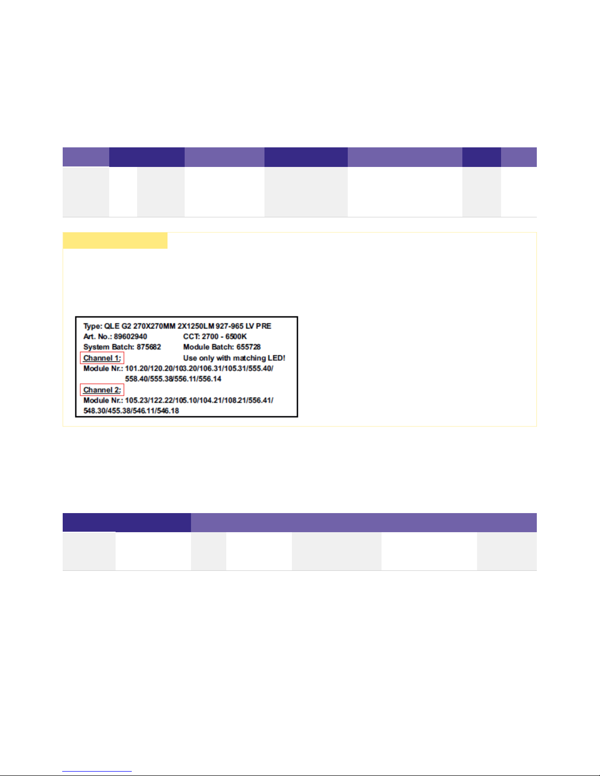
½ CAUTION!
The QLE G2 PRE KIT components form a matched and calibrated unit. Therefore it is not allowed to separate and operate the
components in different combinations!
There is a label on the LCA 50W 350-1050mA DT8 lp PRE or LCA 100W 350-1050mA 2xDT8 lp PRE with the corresponding
module information.

Technical Design-in Guide Engine QLE G2 PRE KIT | 01-2019 | 1.0 | en
System Overview
c
13 / 64
3.4. Versions
3.4.1. QLE G2 PRE KIT
The QLE G2 PRE KIT system is packed with completely new functions such as tunable white. The colour temperature can be changed
smoothly between 2,700 K and 6,500 K to meet the specific needs of the relevant application.
Characteristics:
Control functions:
...
A colour temperature between 2,700 K and 6,500 K that can be set along the Planckian curve_
Different functions packed in a system for individual lighting solutions_
Constant colour temperature over the entire dimming range_
Constant luminous flux_
Lumen values: 1,250 lm_
Colour rendering index CRI > 90_
Very small MacAdam 3 SDCM colour tolerance at 100 % dim level_
System efficiency of up to 136 lm/W with high energy savings_
Temperature monitoring_
DALI Device Type 8_
switchDIM_
colourTEMPERATURE_
Technical Design-in Guide Engine QLE G2 PRE KIT | 01-2019 | 1.0 | en
System Overview
c
14 / 64
3.5. Standards and directives
3.5.1. Standards and directives for modules
The following standards and directives were taken into consideration in designing and manufacturing the modules:
CE
Standard
Description
2006/95/EG
Low-voltage directive: Directive relating to electrical equipment for use within certain voltage limits
2004/108/EG EMC directive: Directive relating to electromagnetic compatibility
RoHS
Standard
Description
2002/95/EC
RoHS directive: Directive on the restriction of the use of certain hazardous substances in electrical and electronic
(1)
equipment
(1)
RoHS: Restriction of (the use of certain) hazardous substances
Safety
Standard
Description
DIN IEC 62031:2008
Safety requirements for LED modules
EN 60598-1:2008 und A11:2009 General requirements and tests for luminaires
EN 60598-2-2:1996 und A1:1997 Luminaires - Part 2. Special requirements;
Main section 2: Recessed luminaires
EN 62471:2008 Photo-biological safety of lamps and lamp systems
Safety and performance
Standard
Description
EN 61347-1:2009
General and safety requirements
EN 61347-2-13:2007 Special requirements for dc and ac powered electronic operating equipment for LED modules
EN 62384:2007 IEC 62384 A1:2009 Operational requirements
Technical Design-in Guide Engine QLE G2 PRE KIT | 01-2019 | 1.0 | en
System Overview
c
15 / 64
Energy labelling
Standard
Description
EU Regulation No: 874/2012
"Energy labelling of electrical lamps and luminaires"
3.5.2. Standards and directives for LED Drivers
The following standards and directives were taken into consideration in designing and manufacturing the LED Driver:
EMI
Standard
Description
EN 55015 2008
Limit values measurement methods for radio interference properties of electrical lighting equipment
and similar electrical devices
EN 61000-3-2:2005 A1: 2008
und A2:2009
Limit values for harmonic currents (equipment input current < 16 A per conductor)
EN 61000-3-3:2005 Limit values for voltage fluctuations and flicker in low-voltage systems for equipment with an input
current < 16 A per conductor that are not
subject to any special connection conditions
EN 61547:2001 EMC requirements
(1)
(1)
EMC: Electromagnetic compatibility
Safety
Standard
Description
EN 50172 2005
Safety lighting systems
DALI
Standard
Description
IEC 62386-101:2009
General requirements, system
IEC 62386-102:2009 General requirements, controller
IEC 62386-207:2009 Special requirements, controller; LED modules
...
Technical Design-in Guide Engine QLE G2 PRE KIT | 01-2019 | 1.0 | en
Mechanical Aspects
c
16 / 64
4.1. Installation
4.1.1. Installation details
Installation example with serial wiring
Installation version IN-BUILT serial wiring with LCA 50W 350-1050mA DT8 lp PRE
...
I NOTICE
EOS/ESD safety guidelines
The device/module contains components that are sensitive to electrostatic discharge and may only be installed in the factory and
on site if appropriate EOS/ESD protection measures have been taken. No special measures need be taken for devices/modules with
enclosed casings (contact with the pc board not possible), just normal installation practice.
Please note the requirements set out in the document EOS/ESD guidelines (Guideline_EOS_ESD.pdf) at:
www.tridonic.com/com/en/download/technical/Guideline_EOS_ESD_en.pdf_
www.tridonic.com/com/en/technical-docs.asp_
Technical Design-in Guide Engine QLE G2 PRE KIT | 01-2019 | 1.0 | en
Mechanical Aspects
c
17 / 64
Installation details
Depending on the particular situation, the LED Driver can be installed in the luminaire casing (in-built) or outside the casing (remote).
Terminals with push button for quick and easy wiring.
Perfectly uniform light, even if several LED modules are used together.
Beveled edges for discreet wiring and easy installation.
4.1.2. Notes on installation
Depending on the installation situation for the LED Driver and the modules, the following requirements must be met:
Protection measures against damage
Mechanical stress
QLE G2 PRE modules contain electronic components that are sensitive to mechanical stress. Such stress should be kept to an absolute
minimum. In particular the following mechanical stresses should be avoided as these may cause irreversible damage:
Adequate distance from insulating materials_
Adequate strain relief for closed covering on the LED Driver_
Adequate cooling of the modules (the maximum temperature at the t point must not be exceeded)
p
_
Unrestricted exit of light from the modules_
Pressure_
Technical Design-in Guide Engine QLE G2 PRE KIT | 01-2019 | 1.0 | en
Mechanical Aspects
c
18 / 64
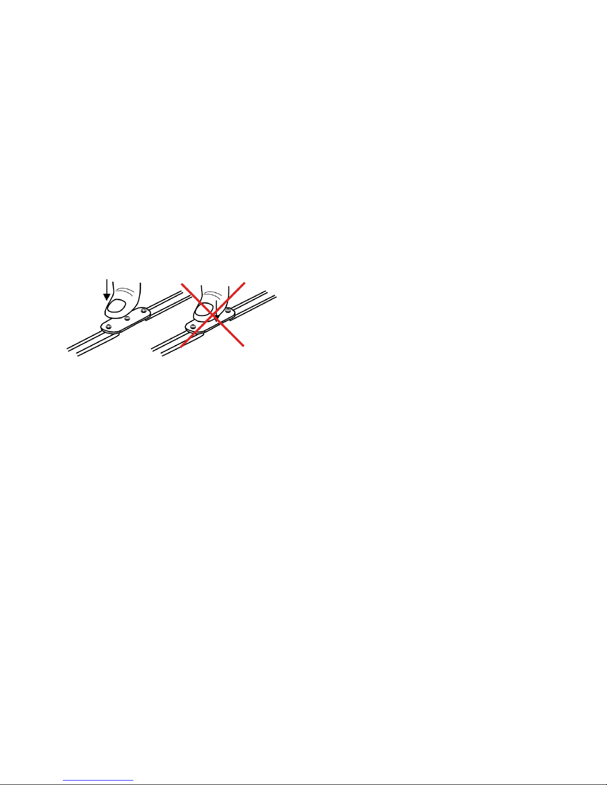
Compressive stresses
The components of the QLE G2 PRE modules (circuit boards, glob-top, lenses, electronic components etc.) are sensitive to
compressive stresses. The components must not be exposed to compressive stresses.
correct (left) and incorrect (right)
Chemical compatibility
LED modules can be damaged by other materials, if these materials have certain chemical properties. The cause for these damages
are different gaseous compounds, which penetrate into the encapsulant of the LED and thereby attack the encapsulant, the colour
conversion phosphor or the LED chips and can affect the electrical contacts or the substrate.
Application areas for chemical substances
The following are known areas in which chemical substances are used:
The following materials must be checked for their safety:
Drilling,_
Milling,_
Breaking,_
Sawing,_
and similar mechanical processing._
If glass or Plexiglas shields are used make sure that pressure is not exerted on the glob-top._
Only touch the QLE G2 PRE modules at the edges_
use of protective coating in applications with high relative humidity (outdoor applications),_
encapsulation of LED modules,_
cementing of LED modules,_
sealing of luminaires._
All components and auxiliaries used in the assembly of the luminaire:_
Solvents of adhesives and coatings_
Other so-called VOC ("volatile organic compounds")_
All other additional substances present in the atmosphere:_
Outgassing of adhesives, sealants and coatings_
Cleaning agents and processing aids (e.g. cutting oils and drilling coolants)_

Technical Design-in Guide Engine QLE G2 PRE KIT | 01-2019 | 1.0 | en
Mechanical Aspects
c
19 / 64
Putting together a "safe list" is not possible due to the complexity of the topic. The following table lists possible contaminants for LED
modules, the classes of compounds and examples of possible sources.
...
I NOTICE
Contact your LED manufacturer for questions about the materials used and possible interactions and risks.
Technical Design-in Guide Engine QLE G2 PRE KIT | 01-2019 | 1.0 | en
Mechanical Aspects
c
20 / 64
The list shows the most commonly used materials but does not claim to be complete.
Class of compounds
Chemical names Occurs in
Acids
Organic acids
Alkalis
Organic solvents
VOC (volatile organic compounds)
Mineral oils
Vegetable oils and synthetic oils
Harder,
vulcanizer
hydrochloric acid_
sulfuric acid_
nitric acid_
phosphoric acid_
cleaner_
cutting oils_
acetic acid_ RTV silicones_
cutting oils_
degreaser_
adhesives_
ammonia_
amines_
sodium hydroxide_
detergents_
cleaner_
ethers (e.g. glycol )_
ketones (e.g. Methylethylketon )_
aldehydes (e.g. formaldehyde)_
aromatic hydrocarbons (e.g. xylene and toluene)_
cleaner_
benzine_
petroleum_
paints and varnishes_
acetate_
acrylates_
aldehydes_
serve_
super glue_
all-purpose glue_
screw locking varnish_
coatings_
paints and varnishes_
hydrocarbons_ machine oil_
lubricants_
siloxanes_
fatty acids_
silicone oils_
linseed oil_
fats_
sulfur compounds_ seals_
sealants_
colours_

Technical Design-in Guide Engine QLE G2 PRE KIT | 01-2019 | 1.0 | en
Mechanical Aspects
c
21 / 64
Protection measures in regards to sealing
The points above also apply to chemicals used for sealing luminaire casings. If however the LED module is not installed in the
luminaire until after the sealing compound has been completely cured (see relevant material information) the above points can be
ignored. If the LED modules have already been installed in the luminaire, possible damage to the encapsulant can be reduced to a
minimum by ensuring adequate spacing (>10 cm) and ventilation (open casing and air circulation, extraction / fan) during the curing
process.
Protection measures in regards to cementing
To avoid damaging the LED modules you must not use any tools or exert any pressure on the electronic components or the
encapsulant.
Instructions for cementing QLE G2 PRE modules
Preparation
Clean and durable bonding of two materials requires special attention. The following cleaning agents are recommended:
Important aspects
Additional information
QLE G2 PRE modules must not be stuck and restuck time and again without replacing the adhesive tape. Damaged adhesive tapes
must be completely removed and replaced by new tapes.
Packaging and transport
QLE G2 PRE Kits from Tridonic are delivered in appropriate packaging. The packaging provides special protection against mechanical
damage and ESD (electrostatic discharge). If you need to transport QLE G2 PRE products you should use this packaging.
If glass or Plexiglas shields are used make sure that pressure is not exerted on the encapsulant._
Only touch the LED modules at the edges_
Isopropanol / Water 50/50_
Acetone_
Heptane_
Carrier material The carrier material must have adequate thermal conductivity (e.g. aluminium). The size of the cooling surface
depends on the power of the LEDs, among other things. For information on the cooling surface required, see the appropriate
product data sheet.
_
Adhesive material The carrier material itself plays an important role in selecting the adhesive material. The crucial factors are
the coefficient of expansion and compatibility with the base material of the module board (plastic or aluminium). This must be
checked in the application in terms of long-term stability, surface contamination and mechanical properties.
_
Surface quality The carrier material must be uncoated (thermal transport, adhesion) and level at the connection points._
Installation temperature To achieve optimum adhesion we recommend you carry out this work at room temperature._
Duration, optimum adhesive strengths Maximum adhesion is achieved within 48 hours at room temperature; the process is
accelerated by heat. In actual practice this means that at the maximum t temperature (approx. 75-85 °C, product-specific)
c
maximum adhesion is reached after about 12 hours. During the curing period make sure that there is no tensile load on the
adhesive connection of the module.
_

Technical Design-in Guide Engine QLE G2 PRE KIT | 01-2019 | 1.0 | en
Mechanical Aspects
c
22 / 64
4.1.3. Installation of the modules on the heat sink
The LED modules are mounted onto a heat sink with 4 screws per module. For optimal thermical connection it is recommended to use
all fastening holes (e.g. 5 screws for the LLE24). In order not to damage the modules only rounded head screws and an additional
plastic flat washer should be used.
Suitable screws should be selected on the basis of the following dimensions:
Dimensions of the fastening screws
Parameters
Value
Bolt size
M4
Max. diameter D 7 mm
Min. length L 5 mm
Max. length L Depending on the design of the luminaire
...

Technical Design-in Guide Engine QLE G2 PRE KIT | 01-2019 | 1.0 | en
Mechanical Aspects
c
23 / 64
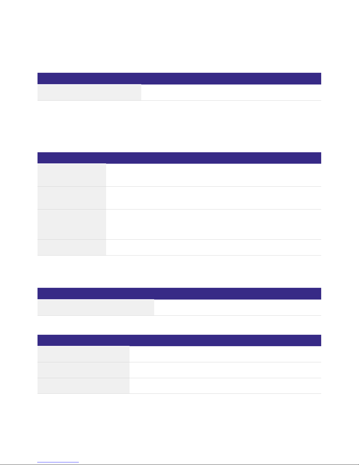
4.2. Dimensional drawings modules
Dimensional drawing of the QLE G2 PRE module
I NOTICE
CAD data for the modules can be downloaded from the Tridonic homepage ( ) and the relevant product page.www.tridonic.com

Technical Design-in Guide Engine QLE G2 PRE KIT | 01-2019 | 1.0 | en
Mechanical Aspects
c
24 / 64
4.3. Dimensional drawings LED Driver
Dimensional drawing of the LED Driver for QLE G2 PRE
...
I NOTICE
Detailed information and CAD data for the LED Driver can be downloaded from the Tridonic homepage ( ) and thewww.tridonic.com
relevant product page.

Technical Design-in Guide Engine QLE G2 PRE KIT | 01-2019 | 1.0 | en
Electrical Aspects
c
25 / 64
5.1. Connections on the LED Driver
5.1.1. Connections on the LED control gear for QLE G2 PRE Module
Pin/Connection
Connection on the LED Driver Design
Protective earth or functional earth Spring terminal
~ Power input Spring terminal
~ Power input Spring terminal
DA* Control input DALI / DSI / switchDIM / corridor FUNCTION Spring terminal
DA* Control input DALI / DSI / switchDIM / corridor FUNCTION Spring terminal
CS colourTEMPERATURE Spring terminal
WW+ QLE G2 PRE Module - warmwhite PLUS Spring terminal
WW- QLE G2 PRE Module - warmwhite MINUS Spring terminal
CW+ QLE G2 PRE Module - coldwhite PLUS Spring terminal
CW- QLE G2 PRE Module - coldwhite MINUS Spring terminal
* only with LED Driver with the corresponding functionality
...

Technical Design-in Guide Engine QLE G2 PRE KIT | 01-2019 | 1.0 | en
Electrical Aspects
c
26 / 64
5.2. Electrical safety
5.2.1. Basic classification of protection classes
Depending on the design of the luminaire, the requirements of different electrical protection classes are satisfied:
Luminaires in protection class III (also SELV which stands for Safety Extra Low Voltage) have such low internal voltages
that a shock current would be inconsequential. AC voltages with an effective value of up to 50 V AC and direct currents up
to 120 V DC are referred to as low voltage (also extra-low voltage and weak current).
Protection class II (non-SELV) applies for luminaires with double insulation, with no protective earth, between the mains
circuit and the output voltage or metal casing. Even if the luminaires have electrically conductive surfaces, thanks to their
insulation they are protected against contact with other live parts.
Protection class I (non-SELV) applies for luminaires with basic insulation and protective earth. All the electrically
conductive casing components are connected via a protective conductor system which is at earth potential.
5.2.2. Basic insulation of QLE G2 PRE modules
The QLE G2 PRE module features basic insulation against earth, i.e., a clearance/creepage distance greater or the same as 3 mm and
can be directly assembled on an earthed metal part of the luminaire, also in operation with LCA 50W 350-1050mA DT8 lp PRE und
LCA 100W 350-1050mA 2xDT8 lp PRE .
5.2.3. Design measures for satisfying protection class requirements
Not all the components of the QLE G2 PRE KIT system comply with the SELV standard. The voltages can thus be greater than 120 V
DC.
5.2.4. Protection class II luminaires
When using a QLE module with NON-SELV level, the following measures are essential in order to achieve protection class II:
5.2.5. Protection class I luminaires
When using a QLE control gear with NON-SELV level, the following measures are essential in order to achieve protection class I:
Reinforced insulation between QLE G2 PRE module and the luminaire casing, e.g., by means of plastic casing or an additional
insulating foil between the luminaire casing and the module.
_
Reinforced insulation between the LED Driver and luminaire casing, e.g., by means of plastic casing_
Use of double-insulated lines_
Protect all electrical contacts against mechanical contact, this can typically be achieved with optics which cannot be removed_
Use of metal casing for the luminaire_
Assembly of the QLE G2 PRE module directly on the casing_
Grounding of the LED Driver, QLE G2 PRE module and the luminaire itself_
Protect all electrical contacts against mechanical contact, this can typically be achieved with optics which cannot be removed_

Technical Design-in Guide Engine QLE G2 PRE KIT | 01-2019 | 1.0 | en
Electrical Aspects
c
27 / 64
...
½ DANGER!
The following measures must be followed in order to avoid life threatening situations:
Electrical work on a luminaire with protection class I or II (non-SELV) must only be carried out by an electrically skilled
person.
_
The luminaire must be disconnected from the mains before starting work on it._
Check the luminaire for damage, if there are any signs of damage, the luminaire must be replaced._

Technical Design-in Guide Engine QLE G2 PRE KIT | 01-2019 | 1.0 | en
Electrical Aspects
c
28 / 64
5.3. Electrical safety and connection
5.3.1. Electrostatic safety and EMC protection
The LED modules are tested up to a voltage of 8 KV static discharging. Depending on the ambient conditions, appropriate
precautionary measures must be taken in order to avoid higher voltages, for example during production or installation.
For good EMC conduct, the lines should be run separately from the mains connections and lines. The maximum secondary line length
on the terminals is 2 metres.
5.3.2. Electrical supply and selection of the LED Driver
...
½ CAUTION!
QLE G2 PRE module are not protected against overvoltages, overcurrents, overloads and short-circuit currents!
Safe and reliable operation of the LED modules can only be guaranteed in conjunction with a LED Driver which complies with the
relevant standards.
QLE G2 PRE module must be supplied by a constant current LED Driver. Operation with a constant voltage LED Driver leads to
irreversible damage to the modules! Wrong polarity can damage the QLE G2 PRE module. If a wire breaks or a complete module
fails in the case of parallel wiring, the current passing through the other modules increases. This may reduce the service life
considerably.

Technical Design-in Guide Engine QLE G2 PRE KIT | 01-2019 | 1.0 | en
Electrical Aspects
c
29 / 64
5.4. Electrical connections
5.4.1. Q LE G2 PRE module connections
The LED Driver is connected to the power supply and the connections of the control lines and the LED module via push-in and spring
terminals:
Line cross-section and stripped length of the insulation on the LED module:
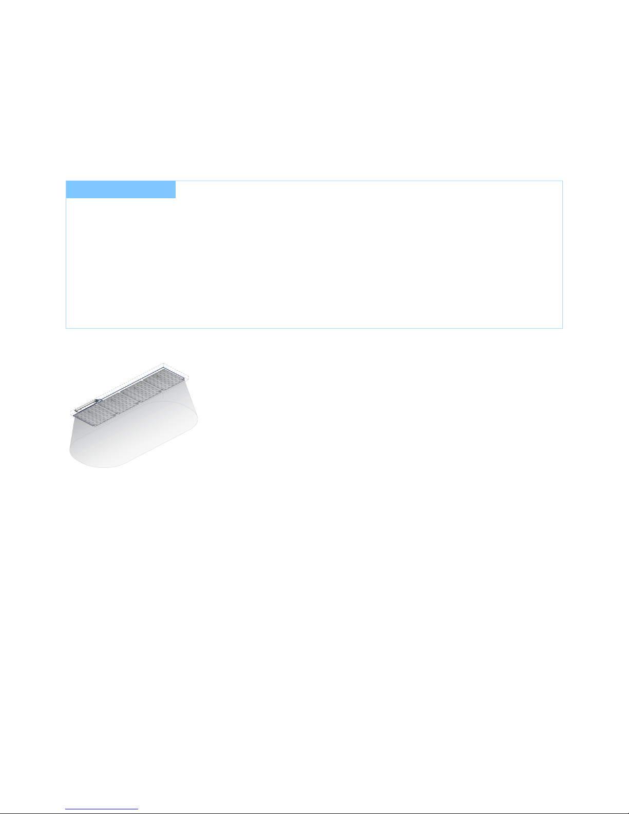
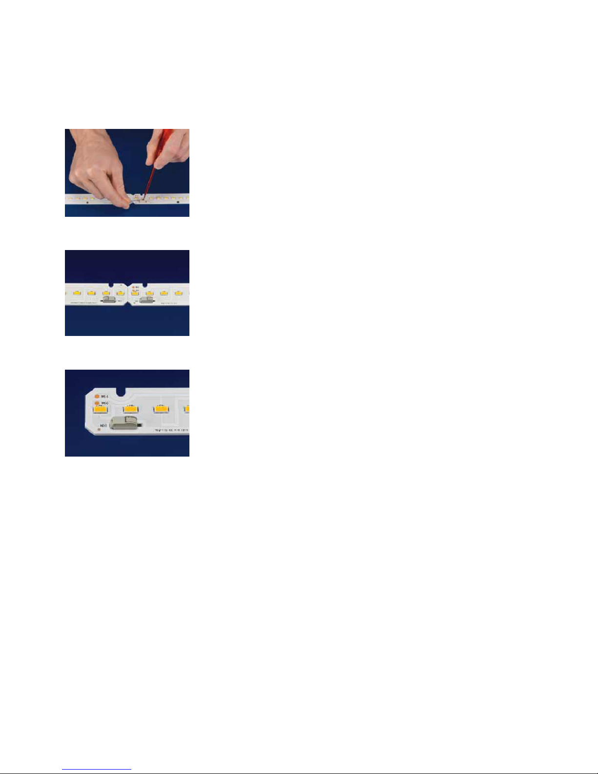
5.4.2. Push-in terminal for solid conductors
Line cross-section on the LED Driver:
Loose wiring
...
Permissible line cross-section: 0.2 - 0.75 mm²_
Stripped length of the insulation 6 - 7 mm_
Push-in terminal for solid conductors_
Permissible line cross-section: 0.5 - 1.5 mm²_
Stripped length of the insulation 8 - 9 mm_
Spring terminal for stranded wire_
Loosen wire through twisting and pulling or using a Ø 1 mm release tool._

Technical Design-in Guide Engine QLE G2 PRE KIT | 01-2019 | 1.0 | en
Electrical Aspects
c
30 / 64
5.5. Wiring diagrams
5.5.1. Wiring diagrams for LCA 50W 350-1050mA DT8 lp PRE
Wiring diagram DALI for QLE PRE (with 2 to 4 modules)
Wiring diagram switchDIM and colourSWITCH for QLE PRE (with 2 to 4 modules)

Technical Design-in Guide Engine QLE G2 PRE KIT | 01-2019 | 1.0 | en
Electrical Aspects
c
31 / 64
5.5.2. Wiring diagrams for LCA 100W 350-1050mA 2xDT8 lp PRE
Wiring diagram DALI for QLE PRE (with 5 to 6 modules)
Wiring diagram switchDIM and colourSWITCH for QLE PRE (with 5 to 6 modules)

Technical Design-in Guide Engine QLE G2 PRE KIT | 01-2019 | 1.0 | en
Electrical Aspects
c
32 / 64
Wiring diagram emergency
...

Technical Design-in Guide Engine QLE G2 PRE KIT | 01-2019 | 1.0 | en
Optical Aspects
c
33 / 64
6.1. Colour spectrum
The used technology enables LEDs to be produced in special light colours or colour temperatures. This means that lighting systems
can be created that are not only energy-efficient but also have excellent colour rendering.
Colour spectrum at different colour temperatures
The diagram shows the normalised intensity in percent over the wave length in nm at different colour temperatures.
...

Technical Design-in Guide Engine QLE G2 PRE KIT | 01-2019 | 1.0 | en
Optical Aspects
c
34 / 64
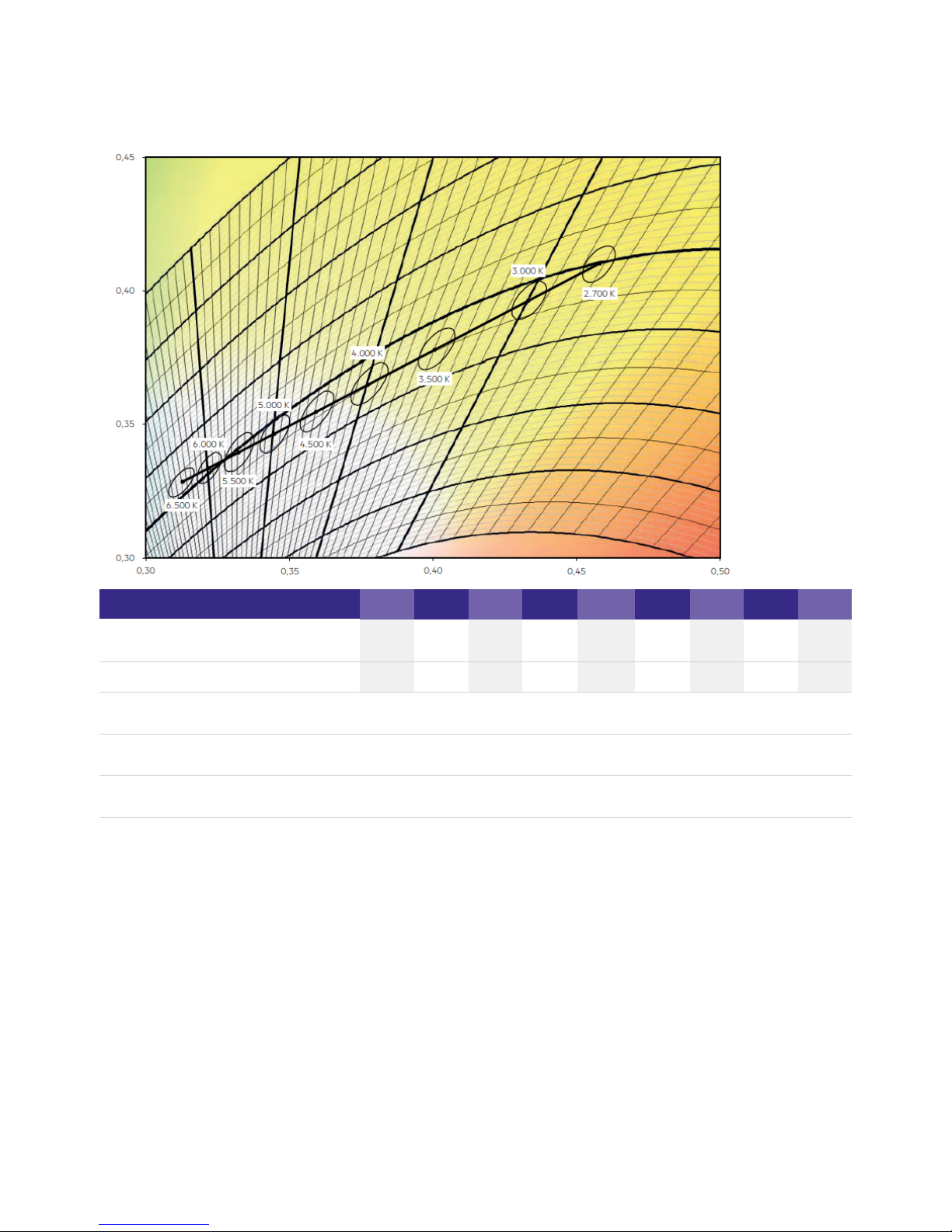
6.2. Coordinates and tolerances
6.2.1. Light colours
QLE G2 PRE KIT covers all the light colours below.
2,700K3,000K3,500K4,000K4,500K5,000K5,500K6,000K6,500
K
Centre x0
0.4578 0.4335 0.4013 0.3778 0.3596 0.3448 0.3324 0.3220 0.3123
Centre y0 0.4101 0.3964 0.3783 0.3651 0.3548 0.3465 0.3395 0.3336 0.3282
MacAdam ellipse 100 – 50 % dimming
level
3 SDCM
MacAdam ellipse 50 – 10 % dimming
level
4 SDCM
MacAdam ellipse 10 – 3 % dimming level 6 SDCM
6.3. CRI, Ra and Ri - different colour rendering values
The CRI (colour rendering index) and Ra (arithmetic average) value are different names for the same thing. They are defined as the
“effect of an illuminant on the colour appearance of objects by conscious or unconscious comparison with their colour appearance
under a reference illuminant”.

Technical Design-in Guide Engine QLE G2 PRE KIT | 01-2019 | 1.0 | en
Optical Aspects
c
35 / 64
CRI and Ra are determined by a test procedure. In this procedure eight colour samples (R1-R8) are illuminated both by the light in
question and by a reference light source and the appearance of the samples under the different lights is compared.
If there is no perceivable difference the light in question will be rated with a maximum value of 100. Differences in appearance result in
a deduction from the maximum value. The resulting number is the Ri value and describes the colour rendering for one specific colour
sample. The average of all eight Ri values is the CRI or Ra value and describes the general colour rendering of the tested light source.
The eight colour samples consist of different pastel colours and can be found in the table below as TCS (test colour samples) 01-08.
There are six more colour samples: R9 to R14 or TCS09 to 14. They consist of different saturated colours and are not used for the
calculation of the Ri, Ra and CRI value. However, these colours, especially R9, do have a special importance in the illumination of meat,
fish, vegetables and fruit in retail areas.
In the production of modules chips with different wavelengths . and chip performances are used
Because of this, different phosphor mixtures are needed to achieve the required target coordinates and single Ri values can differ
between orders. This is not problematic. What is decisive for the overall impression of the LED module is its CRI value. But if specific
single Ri values are required for an application, it must be made clear that these values may change for the reasons stated above. It is
also not possible to specify tolerances.
Special LED modules are optimised to illuminate a particular product group (for example, MEAT+ is designed for the illumination of
the CRI or single Ri values does not make sense. beef). In this case, specifying For special LED modules the subjective human
perception is the most important factor. The colour coordinates for GOLD, GOLD+, Fresh Meat and MEAT+ are the result of
appropriate tests. Single Ri values or the CRI value are not assessed.

Technical Design-in Guide Engine QLE G2 PRE KIT | 01-2019 | 1.0 | en
Optical Aspects
c
36 / 64
6.4. SDCM
The human eye can not only recognise different colours along the black body curve, but also deviations above or below this line. If an
LED has a colour temperature of 2,700 K , but is not directly located on the black body curve, it can be perceived as different from
another LED with the same colour temperature. To prevent such differences and to assign an LED unambiguously, the chromaticity
coordinate must be specified using the x, y coordinates in the colour space chromaticity diagram .
An even more accurate approach is to specify the standard deviation from the target colour, based on levels of MacAdam ellipses. The
unit for this is called "SDCM" (abbreviation for "Standard Deviation of colour Matching"). When looking directly into a light source,
these differences are perceived more strongly than in a "normal" situation where light is mainly perceived because of its reflections
from illuminated surfaces.
Colour differences within one level of the MacAdam ellipses are not visible even when looking directly into the light source. Deviations
of two to three levels (<= 3 SDCM) are considered barely perceptible. A value of 3 SDCM is good for LED light sources. For most
applications a value of 5 SDCM is still sufficient .
6.5. Binning
Chips and packages from the same production can still show small variations in colour temperature and forward voltage . If the chips
are used without pre-selection, these differences can be noticeable and interfere with the appearance.
Binning means that the chips and packages are classified according to their colour temperature and forward voltage. This leads to
groups of chips or packages that fall into a very narrow window of tolerance. If LED modules are equipped with such chips and
packages differences in appearance can be prevented.
6.6. Secondary Optics
The term Secondary Optics refers to additional optical elements that shape the light output in different forms. Secondary Optics
include e.g. reflectors, lenses or covers.
6.7. Coordinates and tolerances (to CIE 1931)
As before, the production process for TALEXX LEDs does without binning. As a result, white LEDs can be produced with normal
distribution in the range of a MacAdam-Ellipse 3. Thanks to the proximity to the Planckian curve there are no annoying colour
discrepancies.
Every module is automatically tested at the final inspection stage to ensure that all the supplied products fall within the agreed
specification.

Technical Design-in Guide Engine QLE G2 PRE KIT | 01-2019 | 1.0 | en
Optical Aspects
c
37 / 64
6.7.1. Chromaticity coordinate
LEDs exhibit variations in terms of their exact shade of colour. This means that different “white” LEDs will all shine in a colour that is
within the white colour spectrum. But the colours won’t be exactly the same.
These colour differences between LEDs are problematic in areas where the lighting must produce a specified and uniform colour and
deviations from that can impair the visual appearance of an installation. Using the chromaticity coordinate helps to avoid such
problems by defining the exact shade of colour of an LED.
Technically speaking, the chromaticity coordinate is defined by its three coordinates (x, y, z) within the so called CIE 1931 colour space
chromaticity diagram.
The CIE 1931 colour space chromaticity diagram represents all the colours that are discernible for humans. Since the three coordinates
sum up to 1, two coordinates are sufficient to define a colour and so one one coordinate is sometimes left out.
6.7.2. Colour temperature and Black Body Curve
The Black Body Curve within the colour space chromaticity diagram represents the colours that show when a so-called "black body" is
slowly heated.
A "black body" is an "idealised" body which absorbs all light and has no reflected radiation.
If a "black body radiator" is slowly heated, it passes through a colour scale from dark red, red, orange, yellow, white to light blue. The
definition for the colour temperature of a light source is the temperature where the “black body radiator” shows the same colour.
The colour temperature is measured in Kelvin (K). The most common luminaires have colour temperatures below 3,300 Kelvin (warm
white), between 3,300 and 5,300 Kelvin (neutral white) or above 5,300 Kelvin (daylight white).

Technical Design-in Guide Engine QLE G2 PRE KIT | 01-2019 | 1.0 | en
Optical Aspects
c
38 / 64
6.7.3. Eye safety
Risk group
Evaluation
Actinic UV E (200 - 400 nm)
S
Risk group 0
(1)
Near UV E (315 - 400 nm)
UVA
Risk group 0
(1)
Blue light L (300 - 700 nm)
B
Risk group 0
(1)
Retina, thermal L (380 - 1,400 nm)
R
Risk group 0
(1)
IR radiation, eye E (780 - 3,000 nm)
IR
Risk group 0
(1)
(1)
The evaluation of eye safety is based on EN 62471:2008 (photo-biological safety of lamps and lamp systems):
...
Risk-free (risk group 0): The LEDs do not pose any photo-biological risk._
Low risk (risk group 1): The LEDs pose a small risk because of normal limitations._
Medium risk (risk group 2): The LEDs pose a small risk because of reactions to bright light sources or thermal discomfort._
High risk (risk group 3): The LEDs pose a risk even with just momentary or temporary exposure._

Technical Design-in Guide Engine QLE G2 PRE KIT | 01-2019 | 1.0 | en
Optical Aspects
c
39 / 64
6.8. Beam characteristics of the QLE G2 PRE module
Maximum relative light intensity lv/v
...

Technical Design-in Guide Engine QLE G2 PRE KIT | 01-2019 | 1.0 | en
Thermal Aspects
c
40 / 64
7.1. Passive cooling
Heat transfer from a heat source to the surrounding cooling medium (e.g. air) depends primarily on the difference in temperature, the
effective surface area and the flow rate of the cooling medium. The function of a heat sink is to increase the surface area over which
the heat can be dissipated. This lowers the thermal resistance.
A passive heat sink works mainly by convection. The surrounding air is heated, which makes it rise, and is replaced by cooler air.
Heat pipes can be used as an alternative to cooing with fans. If space is particularly tight, the heat is first conveyed away. The actual
heat sink is located at the other end of the heat pipe.
Benefits of passive cooling
7.2. Module cooling
7.2.1. Effect of cooling on the life of the modules
The modules of the Engine STARK QLE system are self-cooling and a heat sink is not required. The life of the module depends to a
large extent on the operating temperature. The more that the operating temperature can be reduced, the longer the expected life of
the module. If the permitted operating temperature is exceeded, however, the life of the module will be significantly reduced.
Fall in luminous flux over the course of the service life:
The diagram shows the change in luminous flux in percent over an operating time of 1,000 h at different t operating temperatures.
c
Luminous flux
Operating time at t = 65 °C
c
80 %
30,000 h
70 % 50,000 h
Energy savings_
Silent_
No mechanical wear_
No maintenance_

Technical Design-in Guide Engine QLE G2 PRE KIT | 01-2019 | 1.0 | en
Thermal Aspects
c
41 / 64
50 % 90,000 h
7.2.2. Temperature measurement on the module
There is a t point on top of the module for checking the temperature
c
of the latter:
The temperature at the t point can be measured with a simple
c
temperature probe.
In practice, thermocouples (e.g. B&B Thermotechnik, K-type
thermocouple) have proved successful. Such thermocouples can be
attached directly to the t point with heat-resistant adhesive tape or a
c
suitable adhesive. The measured values are recorded by an electronic
thermometer (e.g., "FLUKE 51", VOLTCRAFT K202 data logger).
The maximum possible temperature must be determined under
worst-case conditions (ambient temperature, installation of the
luminaire) for the relevant application. Before the measurement is
taken, the luminaire should be operated for at least 4 hours in a
draught-free room.
The measurement must be taken in a steady thermal state and in a
draughtfree room.
t point of the module
c
7.2.3. Temperature management of the LED control gear
Although the LED control gear have an integrated temperature management system, the requirements relating to cooling of the LED
control gear must also be taken into account. Unintentional automatic dimming at overtemperature, for example, indicates inadequate
cooling of the LED control gear.
The LED control gear temperature can be measured with a simple temperature probe at the t point. The t point of the LED control
c c
gear is indicated by a sticker on the casing.
I NOTICE
Please check the information on the operating temperature and the requirements for cooling in the module data sheets.
I NOTICE
Measurement conditions, sensors and handling are described in detail in standard EN 60598-1 “General requirements and tests for
luminaires”.
h Sources for suitable eat-conducting foil and paste for the thermal connection of a temperature probe can be found at "partners".

Technical Design-in Guide Engine QLE G2 PRE KIT | 01-2019 | 1.0 | en
Thermal Aspects
c
42 / 64
Relative luminous flux vs. operating temperature
Lifetime characteristic
The table shows the change in luminous flux in percent over an operating time
Forward current
tp temperature L90 / F10 L90 / F50 L80 / F10 L80 / F50 L70 / F10 L70 / F50
825 mA
45 °C >50,000 h >50,000 h >50,000 h >50,000 h >50,000 h >50,000 h
55 °C 30,000 h >50,000 h >50,000 h >50,000 h >50,000 h >50,000 h
65 °C 16,000 h 37,000 h 31,000 h >50,000 h 46,000 h >50,000 h
75 °C 8,500 h 20,000 h 17,000 h 39,000 h 27,000 h >50,000 h
7.2.4. Requirements for the heat sink
Although the operating temperature of the modules is continually monitored during operation and the power is automatically reduced
in the event of excess temperature, the modules should not be operated without a heat sink.
The heat sinks must be dimensioned to provide adequate cooling capacity.
The R value is important for selecting an appropriate heat sink. This value depends on the light output of the module and on the
th
ambient temperature in which the module is to be operated. The R value of the heat sink must be smaller than the required R
th th
value.
I NOTICE
Please check the information on the operating temperature and the requirements for cooling in the module data sheets.

Technical Design-in Guide Engine QLE G2 PRE KIT | 01-2019 | 1.0 | en
Thermal Aspects
c
43 / 64
...
I NOTICE
Please check the information on heat sinks in the module data sheets.

Technical Design-in Guide Engine QLE G2 PRE KIT | 01-2019 | 1.0 | en
Thermal Aspects
c
44 / 64
7.2.5. Effect of cooling on the life of the modules
The modules of the TALEXXengine QLE G2 PRE system are self-cooling and a heat sink is not required. The life of the module
depends to a large extent on the operating temperature. The more that the operating temperature can be reduced, the longer the
expected life of the module. If the permitted operating temperature is exceeded, however, the life of the module will be significantly
reduced.
The diagram shows the change in luminous flux in percent over an operating time of 1,000 h at different t operating temperatures.
c
Luminous flux
Operating time at t = 65 °C
c
80 %
30,000 h
70 % 50,000 h
50 % 90,000 h
I NOTICE
Please check the information on the operating temperature and the requirements for cooling in the module data sheets.

Technical Design-in Guide Engine QLE G2 PRE KIT | 01-2019 | 1.0 | en
Thermal Aspects
c
45 / 64
7.2.6. Temperature measurement on the module
t point QLE
c
There is a t point on top of the module for checking the temperature of the latter:
p
The temperature at the t point can be measured with a simple temperature probe. Since the underside of the modules is made from
p
anodised aluminium, any measurements taken with an infra-red camera would lead to inaccurate results.
In practice, thermocouples (e.g. B&B Thermotechnik, K-type thermocouple) have proved successful. Such thermocouples can be
attached directly to the t point with heat-resistant adhesive tape or a suitable adhesive. The measured values are recorded by an
p
electronic thermometer (e.g., "FLUKE 51", VOLTCRAFT K202 data logger).
The maximum possible temperature must be determined under worst-case conditions (ambient temperature, installation of the
luminaire) for the relevant application. Before the measurement is taken, the luminaire should be operated for at least 4 hours in a
draught-free room.
The measurement must be taken in a steady thermal state and in a draughtfree room.
7.2.7. Temperature management of the LED Driver
Although the LED Driver have an integrated temperature management system, the requirements relating to cooling of the LED Driver
must also be taken into account. Unintentional automatic dimming at overtemperature, for example, indicates inadequate cooling of
the LED Driver.
The LED Driver temperature can be measured with a simple temperature probe at the t point. The t point of the LED Driver is
c c
indicated by a sticker on the casing.

Technical Design-in Guide Engine QLE G2 PRE KIT | 01-2019 | 1.0 | en
Thermal Aspects
c
46 / 64
...
I NOTICE
Measurement conditions, sensors and handling are described in detail in standard EN 60598-1 "General requirements and tests for
luminaires".
Sources for suitable heat-conducting foil and pastes for thermal connection to a temperature probe are given at the end of this
documents.

Technical Design-in Guide Engine QLE G2 PRE KIT | 01-2019 | 1.0 | en
Functions
c
47 / 64
8.1. DSI
8.1.1. Description
DSI (Digital Serial Interface) enables DSI control gear to be controlled. The DSI line can be wired separately via a two-core cable or
together with the mains cable in a five-core cable. Communication is not impaired by the mains cable. In contrast to DALI, there is no
individual addressing of the ballasts with DSI.
DSI offers a series of benefits:
The main benefits of DSI are the optimisation of energy consumption of extensive groups of luminaires (e.g. in sports stadiums and
factories).
8.1.2. Commissioning
Further information can be found in the DALI Handbook (see ).Reference list, S. 64
...
Expansion options via submodules, for example in combination with daylight control or additional switch modules_
Wiring: Simple wiring with five pole standard cables and line length of up to 250 metres_
Wiring: Polarity-free control lines can be used for mains and control lines_
Wiring: Multiple wiring possibilities (star, series and mixed wiring)_
Unaffected by electrical interference_
Uniform light level from the first to the last light source_
reverse polarity protected connection: can be connected with any polarity_
I NOTICE
If the corridorFUNCTION is activated the LED Driver is controlled only by motion. To operate the LED Driver via DALI, DSI or
switchDIM the corridorFUNCTION must be deactivated.

Technical Design-in Guide Engine QLE G2 PRE KIT | 01-2019 | 1.0 | en
switchDIM
c
48 / 64
8.2. switchDIM
8.2.1. Description
With the switchDIM function it is possible to use the mains voltage as a control signal.
The phase of a simple standard mains voltage push button is connected to the terminal marked DA/L and the neutral conductor is
connected to the terminal marked DA/N.
Using the function is easy and convenient:
switchDIM is therefore a very simple form of lighting management. It also has a positive effect on material and labour costs.
The device has a switchDIM memory function. This is used, among other things, for storing the last dimming value in the event of
interruptions in the power supply.
When power returns, the LED is automatically restored to its previous operating state and dimmed to the last value.
8.2.2. Commissioning
Using the switchDIM function
switchDIM is operated by the mains voltage push button.
A short press (50-600 ms) switches the device on or off_
A long press (> 600 ms) fades the connected operating device alternately up and down (between 1 and 100 %)._
½ CAUTION!
Glow switches are not approved for controlling switchDIM.
Glow switches may cause the LED Driver to spontaneously switch on or off or make sudden changes in the dimming value.
½ CAUTION!
To ensure correct operation a sinusoidal mains voltage with a frequency of 50 Hz or 60 Hz is required at the terminal.
Special attention must be paid to achieving clear zero crossings. Serious mains faults may impair the operation of switchDIM and
corridorFUNCTION.
½ CAUTIONS!
A maximum number of 25 operating devices per switchDIM system should not be exceeded.
If you have more devices please use DALI or DSI.
I NOTICE
If the corridorFUNCTION is activated the LED Driver is controlled only by motion. To operate the LED Driver via DALI, DSI or
switchDIM the corridorFUNCTION must be deactivated.

Technical Design-in Guide Engine QLE G2 PRE KIT | 01-2019 | 1.0 | en
switchDIM
c
49 / 64
Procedure:
Synchronising devices
If the devices in a system do not operate synchronously the devices must be synchronised, i.e. put in the same status (on/off).
Procedure:
Changing the fading time
The default value for the fading time is approx. 3 seconds. It can be changed to approx. 6 seconds.
Procedure:
Switching the LED Driver to automatic mode
In automatic mode the device detects which control signal (DALI, DSI, switchDIM, etc.) is connected and automatically switches to the
corresponding operating mode.
Procedure:
8.2.3. Installation
Wiring variants
There are two options for installing switchDIM: four-pole and five-pole wiring
Switch the device on/off by briefly actuating the push button or_
Dim the device by holding down the push button_
Hold down the push button for 10 seconds
-> All devices will be synchronised to the same status
-> LEDs will will be set to a uniform light value (approx. 50 %)
-> The fading time will be set to it default value (approx. 3 seconds)
_
Hold down the push button for 20 seconds
-> After 10 seconds: all devices will be synchronised to the same status
-> After 20 seconds: a fading time of approx. 6 seconds will be set
-> LEDs will be set to a uniform light value (approx. 100 %)
_
Press the push button 5 times within 3 seconds_

Technical Design-in Guide Engine QLE G2 PRE KIT | 01-2019 | 1.0 | en
switchDIM
c
50 / 64
Four-pole wiring
Configuration:
Phase (L), neutral (N), earth (PE), control line (L')
Benefits:
No need for a control line thanks to bridging terminal 8 and the N-connection of the luminaire
Five-pole wiring
Configuration:
Phase (L), neutral (N), earth (PE), control line (L), neutral (N)
Benefits:
Control can be changed at any time to a digital control signal (DSI or DALI) without having to change the luminaire or provide an
additional control line

Technical Design-in Guide Engine QLE G2 PRE KIT | 01-2019 | 1.0 | en
switchDIM
c
51 / 64
...
½ CAUTION!
For five-pole wiring the neutral conductor must be connected to DA/N.
This prevents 400 V being applied between adjacent terminals if a different phase is used for the control input.

Technical Design-in Guide Engine QLE G2 PRE KIT | 01-2019 | 1.0 | en
Power-up fading
c
52 / 64
8.3. Power-up Fading
8.3.1. Description
The power-up fading function offers the opportunity to realise a soft start. The soft start will be applied at turning on the mains and
at starts by switchDIM. The function is programmed as a DALI fade time in the range from 0.7 to 16 seconds and dims in the selected
time from 0% to the power-on level.
By factory default power-up fading is not active (0 seconds).
8.3.2. Commissioning
Procedure via the masterCONFIGURATOR
Further information can be found in the masterCONFIGURATOR manual (see ).Reference list, S. 64
...
Open dialog box "Tridonic-specific configuration"_
Click tab "Power-up Fading"_
Choose value from drop-down menu "Power-up Fading"_
Click "save"
-> Changes are saved
_

Technical Design-in Guide Engine QLE G2 PRE KIT | 01-2019 | 1.0 | en
DALI
c
53 / 64
8.4. DALI
8.4.1. Description
DALI standard
DALI (Digital Addressable Lighting Interface) is an interface protocol for digital communication between electronic lighting
equipment.
The DALI standard was developed by Tridonic together with renowned manufacturers of operating and control equipment. Today,
these manufacturers belong to the DALI Activity Group which promotes the use and further development of DALI.
The DALI standard is defined in IEC 62386. A test procedure standardised by the DALI Activity Group ensures compatibility between
products from different manufacturers. Tridonic products have undergone this test and meet all the requirements. This is indicated by
the logo of the DALI Activity Group on the device.
The agreement by the lighting industry to adopt a common protocol has opened up a virtually unlimited number of options. With the
right choice of individual DALI components an extremely wide range of requirements can be met, from operating a simple light switch
to lighting management systems for entire office complexes with thousands of light sources.
DALI in Action
DALI offers a lot of possibilities:
Technical data of a DALI line:
I NOTICE
LCA PRE devices support the new DALI standard V2 (according to EN 62386-102).
DALI line: 64 LED Driver can be grouped to a line_
DALI groups: Every LED Driver can be attributed into 16 groups_
Addressability: All LED Driver are individually addressable_
Grouping: Possible without complicated rewiring_
Programmability: Individual programmability makes it possible to use functions which transcend the DALI standard_
Monitoring: Easily possible thanks to status feedback_
Wiring: Simple wiring with five pole standard cables and a cable length of max. 300 metres_
Wiring: Polarity-free control lines can be used for mains and control lines_
Wiring: Multiple wiring possibilities (star, series and mixed wiring)_
Unaffected by interruptions: All luminaires receive the same, unaffected digital signal and dimming level_
Similar light level from first to last luminaire_
DALI voltage: 9.5 V - 22.4 DC_
Maximum DALI system current: max. 250 mA_
Data transfer rate: 1200 Baud_
Maximum line length: up to 300 m (for 1,5 mm )
2
_

Technical Design-in Guide Engine QLE G2 PRE KIT | 01-2019 | 1.0 | en
DALI
c
54 / 64
8.4.2. Commissioning
Further information can be found in the DALI Handbook (see ).Reference list, S. 64
eD
eD ("enhanced DALI") offers extended DALI commands. They can be used to activate specific commands of the LED Driver. The
masterCONFIGURATOR software works with eD commands. These commands are Tridonic specific. They are not part of the DALI
standard and are not publicly available.
...
I NOTICE
If the corridorFUNCTION is activated the LED Driver is controlled only by motion. To operate the LED Driver via DALI, DSI or
switchDIM the corridorFUNCTION must be deactivated.

Technical Design-in Guide Engine QLE G2 PRE KIT | 01-2019 | 1.0 | en
Constant Light Output
c
55 / 64
8.5. Constant Light Output
8.5.1. Description
The light output of an LED module reduces over the course of its life. The Constant Light Output function compensates for this
natural decline by constantly increasing the output current of the LED Driver throughout its life. As a results, a virtually uniform light
output is achieved at all times.
For configuration purposes the expected module-specific values for lifetime and residual luminous flux must be specified. The output
current is then controlled automatically on the basis of these values.
The LED Driver typically starts with an output current ("Required Intensity") that corresponds to the expected residual luminous flux
and calculates the increase in the value on the basis of the anticipated lifetime.
If the OTL function is enabled, visual feedback is given as soon as the LED exceeds the expected LED lamp life. If the expected LED
lamp life is exceeded, the luminaire flashes for 2 seconds after being switched on.
8.5.2. Commissioning
Procedure via the masterCONFIGURATOR
Activating the Constant Light Output function
Activating the Over the Lifetime function
I NOTICE
To be able to adjust the parameters "Required intensity", "LED burning hours" and "Expected LED life" the "Advanced settings"
must be activated.
Further information can be found in the masterCONFIGURATOR manual (see ).Reference list, S. 64
Open dialog box "Tridonic-specific configuration"_
Click tab "CLO and OTL"_
Set drop-down menu "Constant intensity" to "enabled"_
Click "save"
-> Changes are saved
_
Open dialog box "Tridonic-specific configuration"_
Click tab "CLO und OTL"_
Set drop-down menu "Visual feedback" to "enabled"_
Click "save"
-> Changes are saved
_

Technical Design-in Guide Engine QLE G2 PRE KIT | 01-2019 | 1.0 | en
Constant Light Output
c
56 / 64
Setting Required intensity and Expected LED life
Transferring existing values to a new LED Driver
If a control gear is replaced the existing parameter values can be transferred to the new LED Driver.
Replacing the LED module
If an LED module is replaced the parameter "LED burning hours" must be set to "0".
Further information can be found in the masterCONFIGURATOR manual (see ).Reference list, S. 64
...
Open dialog box "Tridonic-specific configuration"_
Click tab "CLO and OTL"_
Enter values in input fields "Required intensity" and "Expected LED life"_
Click "save"
-> Changes are saved
_
Chose a control gear that is in the same room as the new control gear_
Open dialog box "Tridonic-specific configuration"_
Click tab "CLO and OTL"_
Note down the values for "Required intensity", "LED burning hours" and "Expected LED life"_
Close dialog box "Tridonic-specific configuration"_
Chose the new control gear_
Open dialog box "Tridonic-specific configuration"_
Click tab "CLO and OTL"_
Take the noted values and enter them in the input fields "Required intensity", "LED burning hours" and "Expected LED life"_
Click "save"
-> Changes are saved
_
Open dialog box "Tridonic-specific configuration"_
Click tab "CLO and OTL"_
Delete value from input field "LED burning hours"
-> CLO function is automatically restarted
-> Changes are saved
_

Technical Design-in Guide Engine QLE G2 PRE KIT | 01-2019 | 1.0 | en
DC-Erkennung
c
57 / 64
8.6. DC recognition
8.6.1. Description
In emergency light systems with central battery supply the DC recognition function uses the input voltage to detect that emergency
mode is in place. The LED Driver then automatically switches to DC mode and dims the light to the defined DC level. Without DC
recognition different and more complex solutions need to be applied in order to detect emergency mode.
8.6.2. Commissioning
The function is integrated in the device as standard. No additional commissioning is necessary for activation.
...
LED Driver of the LCA PRE series are factory preset to a DC level of 15 %. This value can be customised. Further information
can be found in the masterCONFIGURATOR manual (see ).Reference list, S. 64
_
LED Driver of the LC EXC series have different DC levels. Further information can be found in the data sheet of the
corresponding LED Driver (see ).Reference list, S. 64
_
I NOTICE
The LED Driver is designed to operate on DC voltage and pulsing DC voltage.
In DC recognition connected sensors are ignored.

Technical Design-in Guide Engine QLE G2 PRE KIT | 01-2019 | 1.0 | en
Dimming on DC
c
58 / 64
8.7. Dimming on DC
8.7.1. Commissioning
Procedure with masterCONFIGURATOR
Further information can be found in the masterCONFIGURATOR manual (see ).Reference list, S. 64
...
½ WARNING!
If Dimming on DC is activated then emergency mode is not recognised. The device no longer automatically switches to the
emergency light level.
Make sure that if Dimming on DC is activated an appropriate dimming level is selected for the emergency lighting mode.
Please also note the following:
Dimming on DC may only be activated by trained personnel_
A security code must be entered before activation_
The security code is issued only after a consent form has been signed_
Dimming on DC must not be used in emergency lighting systems to EN 50172_

Technical Design-in Guide Engine QLE G2 PRE KIT | 01-2019 | 1.0 | en
Intelligent Temperature Guard
c
59 / 64
8.7.2. Description
If Dimming on DC is activated the requirements of the DC recognition function are ignored. Even if DC is detected the LED Driver
continues to behave as in AC mode:
8.8. Intelligent Temperature Guard
8.8.1. Description
The Intelligent Temperature Guard function provides protection against temporary thermal overloads. It slowly reduces the output if
the maximum T temperature is exceeded. This way instant failure of the LED Driver can be prevented. Thermal overload protection is
c
triggered as soon as the T temperature is exceeded by around 5 to 10 °C. The precise trigger temperature depends on the device.
c
The value is selected so that the protection function is not performed until there is a significant impact on rated life.
The output is reduced in small stages that are generally imperceptible to the user. The temperature is checked every two minutes.
8.8.2. Behaviour
The following table shows the exact behaviour and parameters of the Intelligent Temperature Guard function for LCA PRE and LC
EXC
Parameters
Description
Start of power reduction
When maximum operating temperature (Tc) is exceeded by approx. 5-10 °C
(1)
Power reduction rate
Reduction of max level by 1 dim step / 2 min
Power reduction process
and control
Power reduction is dependent on temperature:
Min power level
approx. 50 % dim level
(2)
The present dimming level is retained_
An emergency light level defined for the DC recognition function (DC level) is ignored_
Control signals via DALI und DSI continue to be executed_
½ WARNING!
The T temperature is the maximum permitted in terms of safety.
c
Operating the LED Drivers above the permitted T temperature is not compliant with relevant standards.
c
The Intelligent Temperature Guard function does not replace the proper thermal design of the luminaire and does not enable the
lighting to operate for lengthy periods of time in impermissible ambient temperatures.
Power reduction continues if temperature still rises_
Power reduction stops if temperature does not rise anymore or if maximum power reduction is
reached (minimum power level = 50 %)
_
If temperature falls below a certain level, power is increased again until 100 % is reached_
If temperature still rises even if maximum power reduction is reached:_
PRE drivers go to 15 % dim level_

Technical Design-in Guide Engine QLE G2 PRE KIT | 01-2019 | 1.0 | en
Intelligent Temperature Guard
c
60 / 64
Shut off behaviour
No shut off behaviour:
Device will not shut off if temperature still rises.
Automatic restart
behaviour
No automatic restart behaviour (because there is no shut off behaviour)
Restart temperature
No restart temperature
(1)
Rated T is device specific.
c
...
AC mode: Device switches to 15 % dimming level_
DC mode: Intelligent Temperature Guard is not relevant because driver goes to EOFx level anyway_
I NOTICE
The standard setting for the dimming curve is logarithmic:
If alternative dimming curves are used the power reduction can be implemented differently.

Technical Design-in Guide Engine QLE G2 PRE KIT | 01-2019 | 1.0 | en
Ordering information and sources
c
61 / 64
9.1. Article numbers
9.1.1. QLE G2 PRE KIT > 90 (calibrated kit)
Type
Colour-
temperature (K)
Typ. luminous
flux (lm)
1)
CRI
Typ. power
draw (W)
1)
System
efficacy
(lm/W) Order No.
QLE G2 270x270mm 2x1250lm
927-965 LV PRE
(LCA 50W PRE LED-Driver + 2
LED-Module a 1250lm)
2,700-6,500
Tunable White
2,500 > 90 19.8 126 89602940
QLE G2 270x270mm 3x1250lm
927-965 LV PRE
(LCA 50W PRE ED-Driver + 3
LED-Module a 1250lm)
2,700-6,500
Tunable White
3,750 > 90 28.4 132 89602941
QLE G2 270x270mm 4x1250lm
927-965 LV PRE
(LCA 50W PRE ED-Driver + 4
LED-Module a 1250lm)
2,700-6,500
Tunable White
5,000 > 90 36.9 135 89602942
QLE G2 270x270mm 5x1250lm
927-965 LV PRE
(LCA 100W PRE ED-Driver + 5
LED-Module a 1250lm)
2,700-6,500
Tunable White
6,250 > 90 46.5 134 89602943
QLE G2 270x270mm 6x1250lm
927-965 LV PRE
(LCA 100W PRE ED-Driver + 6
LED-Module a 1250lm)
2,700-6,500
Tunable White
7,500 > 90 55.1 136 89602944
All of the above QLE PRE kits meet MacAdam (SDCM 3 @ 100% Dimmlevel) and have a uniform size of 270 x 270 mm.
1)
Tolerance range for optical data: ±5 % and tolerance range for electrical data: ±5 %.
9.1.2. Suitable controllers
Tridonic offers a comprehensive range of DALI-compatible products. All the devices specified here support DALI Device Type 6 and
therefore guarantee effective use of LLE PRE KIT.
Product name
Article No.
DALI MSensor 02
28000896

Technical Design-in Guide Engine QLE G2 PRE KIT | 01-2019 | 1.0 | en
Ordering information and sources
c
62 / 64
DALI SC 24034263
DALI MC 86458507
DALI TOUCHPANEL 02 28000022
DALI x/e-touchPANEL 02 28000005
DALI PS 24033444
DALI USB 24138923
9.2. Product application matrix
Whether you are looking for wide-area lighting or focused accent lighting, our wide range of PRE products will help you create an
individual atmosphere and highlight specific areas exactly as you want. Our product portfolio includes individual light points, round,
rectangular and strip versions. Specially matched operating equipment such as LED Driver, amplifiers and sequencers round off the
components for a perfect system solution: They guarantee ideal operation and maximum efficiency.
9.2.1. Luminaire application PRE KIT
PRE KIT
Downlight Spotlight
Linear /
rectangular Decorative Surface Outdoor (street)
PRE KIT DLE
PRE KIT SLE
PRE KIT LLE
PRE KIT FULMEN
PRE KIT LINE
I NOTICE
Go to to see the current range of products and the latest software updates.www.tridonic.com

Technical Design-in Guide Engine QLE G2 PRE KIT | 01-2019 | 1.0 | en
Ordering information and sources
c
63 / 64
9.2.2. Luminaire application PRE module
PRE module
Downlight Spotlight
Linear /
rectangular Decorative Surface Outdoor (street)
PRE module SPOT
PRE module RECTANGULAR
PRE module EOS
PRE module STRIP
PRE module TAPE
For more information and technical data on the entire PRE product portfolio go to or see our PRE catalogue.led.tridonic.com
...

Technical Design-in Guide Engine QLE G2 PRE KIT | 01-2019 | 1.0 | en
Reference list
c
64 / 64
10.1. Related documents
10.2. Downloads
10.3. Additional information
Data sheet Module QLE G2 PRE: https://www.tridonic.com/com/en/download/data_sheets/Module_QLE_G2_PRE_en.pdf_
DALI manual: http://www.tridonic.com/com/en/download/technical/DALI-manual_en.pdf_
Documentation masterCONFIGURATOR: http://www.tridonic.com/com/en/download/Manual_masterConfigurator_en.pdf_
corridorFUNCTION: http://www.corridorfunction.com/corridorFUNCTION/index.html_
Tridonic software: http://www.tridonic.com/com/en/software.asp_
Download masterCONFIGURATOR: http://www.tridonic.com/com/de/software-masterconfigurator.asp_
Download Android-App Emergency ADDRESSING Decoder:
https://play.google.com/store/apps/details?id=net.gmx.royder.knight.EZ_easyADRESSING
_
Declarations of conformity: http://www.tridonic.com/com/en/news-declarations-of-conformity.asp_
Company certificates: http://www.tridonic.com/com/en/company-certificates.asp_
Guarantee conditions: http://www.tridonic.com/com/en/guarantee.asp_
Data sheets: http://www.tridonic.com/com/en/data-sheets.asp_
Environmental declarations: http://www.tridonic.com/com/en/environmental-declarations.asp_
Tender text: http://www.tridonic.com/com/en/tender.asp_
Other technical documents: http://www.tridonic.com/com/en/technical-docs.asp_
Product catalogue: http://www.tridonic.com/com/en/catalogue.asp_
 Loading...