

Tridonic LuxControl DALI XC User Manual

luxCONTROL
DALI XC

Copyright
Copyright © Tridonic GmbH & Co KG
All rights reserved.
Manufactur er
Tridonic GmbH & Co KG
Färbergasse 15
6851 Dornbirn
Austria
Tel. +43-(0)5572-395-0
Fax +43-(0)5572-20176
www.tridonic.com
Document number
DALI XC_IB 3.0 | 01.2014 | en

Table of contents
1 How to use this manual
2 Safety instructions
3 Device descr iption
4 Project design
5 Commissioning
6 Saving scenes
7 Regrouping luminaires
..................................................................................................................................4
..................................................................................................................................5
..................................................................................................................................6
...............................................................................................................................73.1 Application area
...............................................................................................................................73.2 Operating modes
...............................................................................................................................83.3 Acoustic signals
..................................................................................................................................9
..................................................................................................................................12
...............................................................................................................................135.1 Starting commissioning
...............................................................................................................................155.2 Grouping luminaires
...............................................................................................................................165.3 Finishing commissioning
..................................................................................................................................17
..................................................................................................................................18
8 Operation
9 System extension
10 Technical data
..................................................................................................................................21
...............................................................................................................................218.1 Changing intensity
...............................................................................................................................238.2 Changing colour temperature
...............................................................................................................................238.3 Recalling scenes
..................................................................................................................................24
...............................................................................................................................249.1 Starting system extension
...............................................................................................................................269.2 Adding or changing luminaires
...............................................................................................................................279.3 Adding or changing DALI XC devices
...............................................................................................................................289.4 Finishing system extension
..................................................................................................................................29
.............................................................................................................21Single momentary-action switch control8.1.1
.............................................................................................................22Double momentary-action switch control8.1.2
DALI XC_IB 3.0 | 01.2014 | en 3
How to use this manual
i
Note
These commissioning instructions describe how to use the DALI XC in the comfortDIM system.
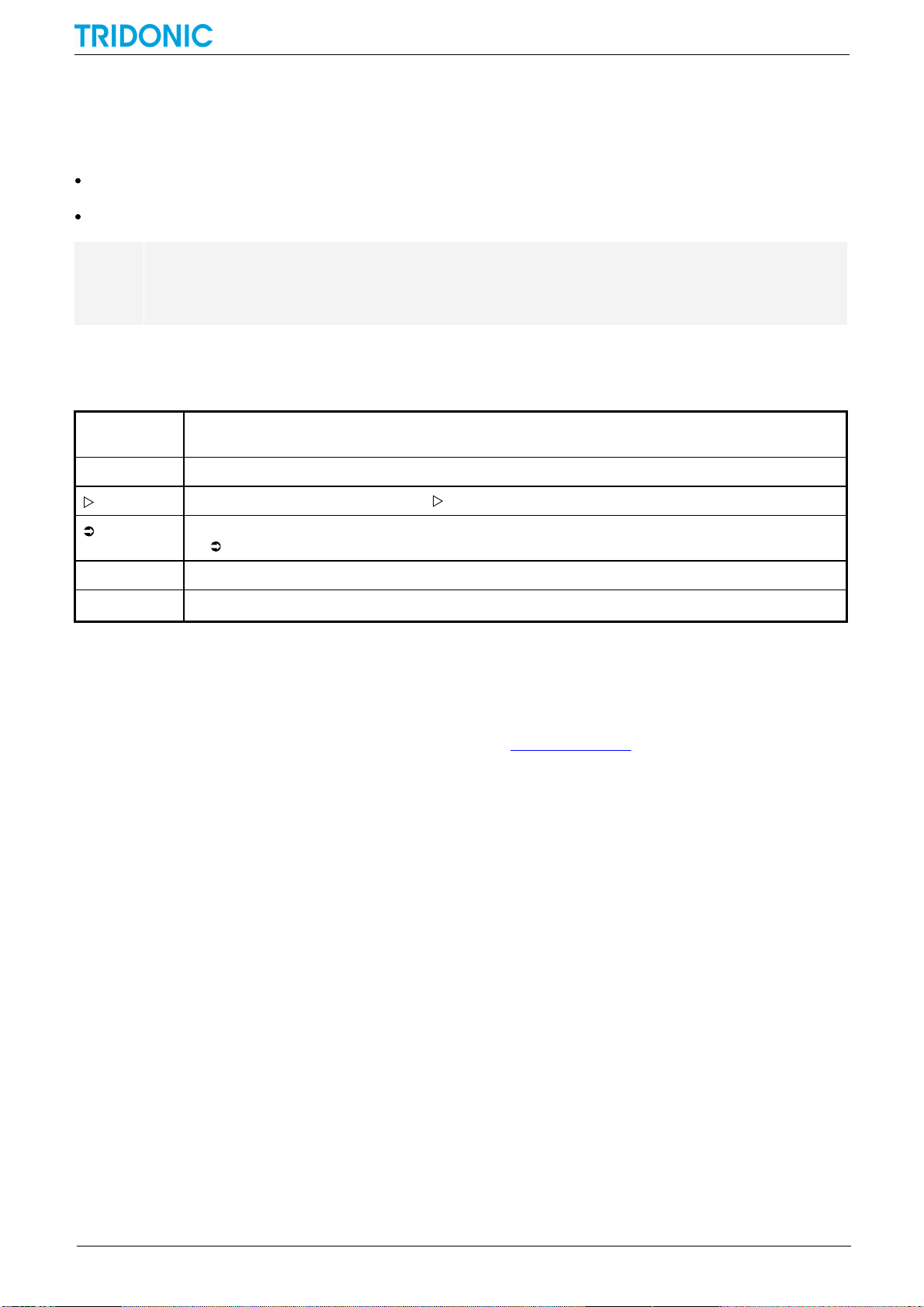
Character/
symbol
Description
1.
Individual steps in the instructions are numbered.
Single-step instructions are indicated by at the beginning of the line.
After a step has been described, a description of the expected results will follow. These results are indicated
by at the beginning of the line.
—
Requirements which need to be checked before carrying out a step are indicated by —.
i
Notes can be recognised by i. In addition, notes are identified by the word Note.
1 How to use this manual
We are pleased that you have chosen this Tridonic GmbH & Co KG product. So that you can get the most from this
manual, the following information will be set out in this section:
Characters and symbols in this manual
Further information
Characters and symbols in this manual
The following characters and symbols are used in this manual:
Table 1: Characters and symbols in this manual
Further information
More information on installing the DALI XC can be found in the installation instructions supplied with the device.
General information on our products can be found on our website: www.tridonic.com
DALI XC_IB 3.0 | 01.2014 | en 4

Safety instructions
2 Safety instructions
The device may only be used for the application area specified.
Relevant health and safety regulations must be observed.
When assembling and installing the device, the voltage supply must be disconnected.
Only qualified personnel may assemble, install and commission the device.
If an error occurs, dangerous voltage levels may be present at the DALI terminals and on the DALI control line.
DALI XC_IB 3.0 | 01.2014 | en 5
3 Device description
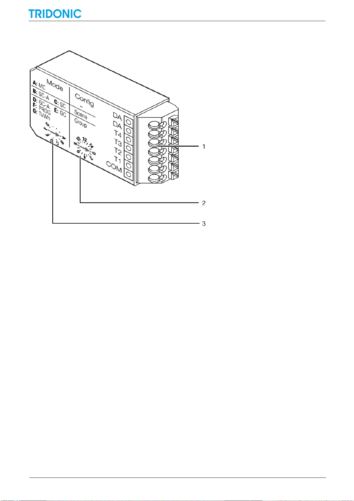
Figure 1: DALI XC input device
Device description
(1) Terminals
(2) "Config" rotary selector switch
(3) "Mode" rotary selector switch
DALI XC_IB 3.0 | 01.2014 | en 6

Device description
Figure 2: DALI XC in a lighting system as part of the comfortDIM system
i
Note
More information can be found in the masterCONFIGURATOR software user manual installed with the
software. The user manual can also be downloaded from the Tridonic website.
3.1 Application area
The DALI XC is a device with four inputs for controlling lighting with single momentary-action switches, double
momentary-action switches and standard switches, which can be combined in some operating modes. The DALI XC
is supplied by the DALI control line. For this reason, a device that provides the voltage supply is required for use in a
lighting system (e.g. DALI PS2).
3.2 Operating modes
The Mode rotary selector switch is used to set the operating mode. Every letter A–G on the Mode rotary selector
switch stands for an operating mode specified on the device. If the rotary selector switch is not turned to a marked
position, the DALI XC will not function.
"MC" operating mode
Rotary selector switch position A
Single momentary-action switches and/or double momentary-action switches and/or standard switches can be used
to recall programmed functions. The MC operating mode can only be configured using the masterCONFIGURATOR
software versions 2.10 and higher. The device does not function in MC operating mode by default.
A DALI XC device in MC operating mode can replace the DALI MC (art. No 86458507).
"SC-A" operating mode
Rotary selector switch position B
Single momentary-action switches can be used to recall scenes. No scenes can be saved in this operating mode.
A DALI XC device in SC-A operating mode can replace the DALI SC-A (art. No 24138906).
DALI XC_IB 3.0 | 01.2014 | en 7

Device description
"SC" operating mode
Rotary selector switch position C
Single momentary-action switches can be used to recall and save scenes.
A DALI XC device in SC operating mode can replace the DALI SC (art. No 24034263).
"GC-A" operating mode
Rotary selector switch position D
Single momentary-action switches and/or double momentary-action switches can be used to switch luminaire groups
on/off and brighten or dim them. Programming mode cannot be enabled in the operating mode. If the lighting system
is switched to programming mode using another DALI XC device, the momentary-action switches connected to the
DALI XC in GC-A operating mode can be used to group luminaires.
A DALI XC device in GC-A operating mode can replace the DALI GC-A (art. No 24138907).
"GC" operating mode
Rotary selector switch position E
Single momentary-action switches and/or double momentary-action switches can be used to switch luminaire groups
on/off and brighten or dim them. A system extension is typically started in this operating mode. If the lighting system is
in programming mode, the momentary-action switches connected to the DALI XC in GC operating mode can be used
to group luminaires.
A DALI XC device in GC operating mode can replace the DALI GC (art. No 24033450).
"Prog" operating mode
Rotary selector switch position F
Commissioning or a system extension can be started and completed in this operating mode. The lighting system is in
programming mode while these processes are ongoing.
"TuWh" operating mode
Rotary selector switch position G
Double momentary-action switches can be used to set the intensity and colour temperature of Tunable White
luminaires.
3.3 Acoustic signals
Some actions on the DALI XC elicit a different number of high beeps. During configuration, beeping indicates that
some steps have been reached.
The DALI XC beeps three times when the voltage supply has been established.
In programming mode, the DALI XC beeps once each time a momentary-action switch is pressed.
The DALI XC beeps once, twice or three times after various configuration steps.
The DALI XC beeps once after approx. 1 s when one of the rotary selector switches is turned to a new position.
DALI XC_IB 3.0 | 01.2014 | en 8

4 Project design
i
Note
The maximum number of DALI XC devices that can be used in a lighting system depends on the total
power consumption of the devices connected to the DALI control line. The power consumption of the
individual devices can be found in the associated data sheets.
The following information applies to the use of the DALI XC in the comfortDIM system.
Rotary selector switch
position
Group
Input
T1 and T2
Input
T3 and T4
0
all11122233344455566677788899910101011111112121213131314141415151516
The following conditions apply for the project design of a lighting system with DALI XC:
No more than 64 DALI-compatible control gear elements can be used.
No more than 16 groups can be configured.
A luminaire can be assigned to max. 16 groups.
No more than 16 scenes can be configured.
Assigning groups to inputs (DALI XC in "GC-A" or "GC" operating mode)
Project design
Rotary selector switch position D or E
The Config rotary selector switch is used to assign different groups to input T1 and T2 and input T3 and T4.
The following table uses the rotary selector switch position to indicate which group is assigned to the inputs.
Table 2: Assigning groups to inputs (DALI XC in "GC-A" or "GC" operating mode)
DALI XC_IB 3.0 | 01.2014 | en 9
 Loading...