

Product description
• Independent dimmable constant current 2-channel LED Driver
with DALI DT6 and strain-relief
• Dimming range 1 – 100 %
• Suitable for luminaires of protection class I and protection class II
• Adjustable output current between 350 and 1,050 mA for each
channel via I-SELECT 2 plugs or DALI
• Max. output power 38 W
• Up to 89 % eiciency
• Power input on stand-by < 0.25 W
• Nominal lifetime up to 100,000 h
• 5 years guarantee
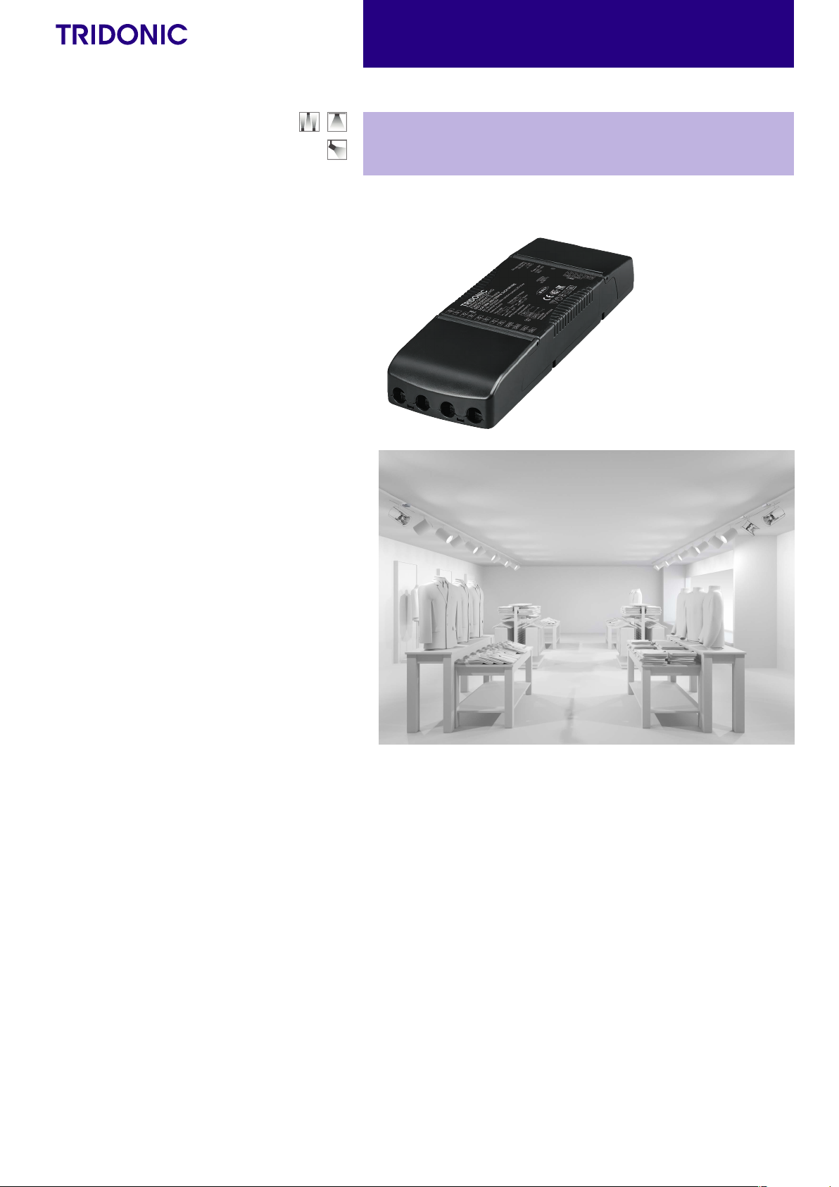
LED Driver
Compact dimming
Driver LCA 38W 350–1050mA 2xCH SR PRE
premium series
Housing properties
• Casing: polycarbonate, black
• Type of protection IP20
• Strain relief with loop through function
Interfaces
• one4all (DALI DT6, DSI, switchDIM, corridorFUNCTION V2)
• proportionSWITCH
• Terminal blocks: 45° / 0° push terminals
Functions
• Adjustable output current in 1-mA-steps (DALI, I-SELECT 2)
• Constant light output function (CLO)
• proportionSWITCH with pre defined scenes (split between
dierent channel scenes)
• switchDIM and proportionSWITCH with memory function
• Power-up fading and fade2zero
• Configurable via DALI
• Protective features (overtemperature, short-circuit, overload,
no-load, reduced surge amplification)
• Intelligent Voltage Guard (overvoltage and undervoltage
monitoring)
• Suitable for emergency lighting acc. to EN 50172
Benefits
• Application-oriented operating window for max. compatibility
• Best energy savings due to low stand-by losses
Typical applications
• For spot light and downlight in retail and hospitality applications
• Direct and indirect lighting application
È
Standards, page 4
Data sheet 03/21-LC573-8
Subject to change without notice. Information provided without guarantee.
www.tridonic.com
1
EL
37
Technical data
Rated supply voltage 220 – 240 V
AC voltage range 198 – 264 V
DC voltage range 176 – 288 V
Mains frequency 0 / 50 / 60 Hz
Overvoltage protection 320 V AC, 48 h
Typ. current (at 230 V, 50 Hz, full load)
Typ. current (220 V, 0 Hz, full load, 15 % dimming level)
Leakage current (at 230 V, 50 Hz, full load)
Typ. eiciency (at 230 V / 50 Hz / full load)
λ (at 230 V, 50 Hz, full load)
Typ. power input on stand-by
Typ. input current in no-load operation
Typ. input power in no-load operation
In-rush current (peak / duration)
THD (at 230 V, 50 Hz, full load)
Starting time (at 230 V, 50 Hz, full load)
Starting time (DC mode) < 0.4 s
Switchover time (AC/DC)
Turn o time (at 230 V, 50 Hz, full load) < 20 ms
Output current tolerance
Max. output current peak (non-repetitive) ≤ output current + 20 %
Output LF current ripple (< 120 Hz) ± 2 %
LM
Output P
st
Output SVM (at full load) ≤ 0.4
Max. output voltage (no-load voltage) 60 V
Dimming range 1 – 100 %
Mains surge capability (between L – N) 1 kV
Mains surge capability (between L/N – PE) 2 kV
Surge voltage at output side (against PE) < 500 V
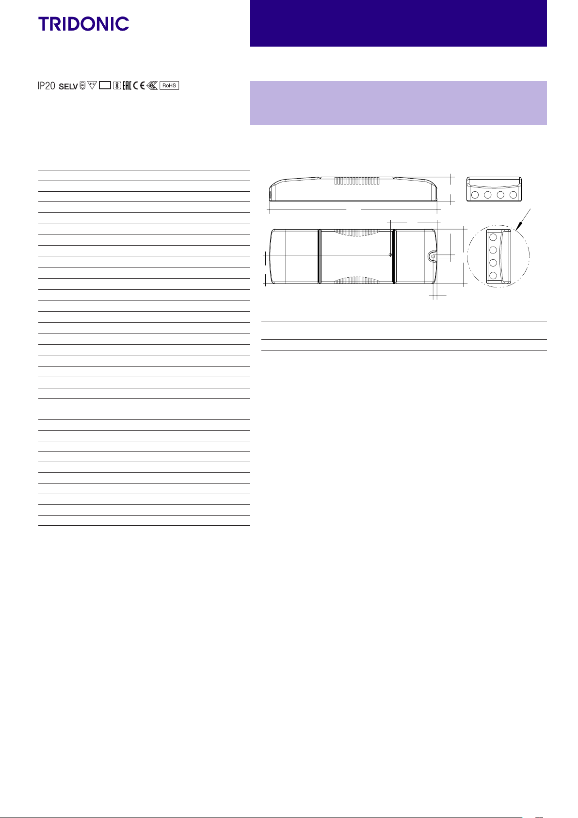
Type of protection IP20
Lifetime up to 100,000 h
Guarantee 5 years
Dimensions L x W x H 215 x 70 x 31 mm
7
16
(at full load) ≤ 1
12
12
2
1
3
1
1
173 – 201 mA
2
55 mA
< 500 µA
89 %
> 0.98
< 0.25 W
22 mA
< 0.5 W
26.4 A / 224 µs
< 10 %
< 0.6 s
< 0.2 s
± 3 %
LED Driver
Compact dimming
Driver LCA 38W 350–1050mA 2xCH SR PRE
premium series
31
215
60
5
Packaging
carton
Ø4.2
70
Packaging
pallet
Weight per pc.
tc
Ordering data
Type Article number
LCA 38W 350–1050mA 2xCH SR PRE 28002204 10 pc(s). 400 pc(s). 0.238 kg
Ø75
Data sheet 03/21-LC573-8
Subject to change without notice. Information provided without guarantee.
www.tridonic.com
2

LED Driver
Compact dimming
Specific technical data
Type Output
current for
channel
LCA 38W 350–1050mA 2xCH SR
PRE
1,000 mA 20 V 38.0 V 38.0 W – – – – 5.00 kΩ
1,050 mA 20 V 36.2 V 38.0 W
1
Valid at 100 % dimming level.
2
Depending on the selected output current.
3
Depending on the DALI traffic at the interface.
4
The table only lists a number of possible operating points but does not cover each single point. The output current can be set within the total value range in 1-mA-steps.
5
Not compatible with I-SELECT (generation 1). Calculated resistor value.
6
Output current is mean value set equally for both channels.
7
Valid for immediate change of power supply type otherwise the starting time is valid.
each
Min. forward
per channel
46
voltage
Max. forward
voltage
per channel
Max. output
power
per channel
Typ. power consumption
(at 230 V, 50 Hz, full load)
Typ. current consumption
(at 230 V, 50 Hz, full load)
Max. casing
temperature tc
350 mA 20 V 50.0 V 17.5 W 39.3 W 173 mA 75 °C -25 ... +55 °C open
400 mA 20 V 50.0 V 20.0 W 42.9 W 189 mA 75 °C -25 ... +50 °C 12.50 kΩ
450 mA 20 V 50.0 V 22.5 W 43.0 W 189 mA 75 °C -25 ... +50 °C 11.11 kΩ
500 mA 20 V 5 0.0 V 25.0 W 43.4 W 191 mA 75 °C -25 ... +50 °C 10.00 kΩ
550 mA 20 V 50.0 V 2 7.5 W 43.6 W 192 mA 75 °C -25 ... +50 °C 9.09 kΩ
600 mA 20 V 50.0 V 3 0.0 W 43.9 W 193 mA 75 °C -25 ... +50 °C 8.33 kΩ
650 mA 20 V 50.0 V 32.5 W 44.2 W 194 mA 75 °C -25 ... +50 °C 7.69 kΩ
700 mA 20 V 50.0 V 35.0 W 44.1 W 194 mA 75 °C -25 ... +50 °C 7.14 kΩ
750 mA 20 V 50.0 V 37.5 W 44.6 W 196 mA 75 °C -25 ... +45 °C 6.67 kΩ
800 mA 20 V 47. 5 V 38 .0 W 45.1 W 198 mA 75 °C -25 ... +45 °C 6.25 kΩ
850 mA 20 V 44.7 V 38.0 W 45.1 W 198 mA 75 °C -25 ... +45 °C 5.88 kΩ
900 mA 20 V 42.2 V 38.0 W 45.8 W 201 mA 75 °C -25 ... +45 °C 5.56 kΩ
950 mA 20 V 40.0 V 38.0 W 45.7 W 201 mA 75 °C -25 ... +45 °C 5.26 kΩ
– – – –
Ambient
temperature ta max.
I-SELECT 2
resistor value
short circuit (0 Ω)
4
Data sheet 03/21-LC573-8
Subject to change without notice. Information provided without guarantee.
www.tridonic.com
3

LED Driver
9
Compact dimming
Product description
• Ready-for-use resistor to set output current value
• Compatible with LED Driver featuring I-SELECT 2 interface;
not compatible with I-SELECT (generation 1)
• Resistor is base insulated
• Resistor power 0.25 W
• Current tolerance ± 2 % additional to output current tolerance
• Compatible with LED Driver series PRE and EXC
Example of calculation
• R [kΩ] = 5 V / I_out [mA] x 1000
• E96 resistor value used
• Resistor value tolerance ≤ 1 %; resistor power ≥ 0.1 W;
base insulation necessary
• When using a resistor value beyond the specified range, the
output current will automatically be set to the minimum value
(resistor value too big), respectively to the maximum value
(resistor value too small)
I-SELECT 2 PLUG PRE / EXC
SORIES
ACCES-
5,5
xxxx
xxxx
Ordering data
Type
I-SELECT 2 PLUG 350MA BL Blue 0350 mA 350 mA 14.30 kΩ 10 pc(s). 0.001 kg
I-SELECT 2 PLUG 375MA BL Blue 0375 mA 375 mA 13.30 kΩ 10 pc(s). 0.001 kg
I-SELECT 2 PLUG 400MA BL Blue 0400 mA 400 mA 12.40 kΩ 10 pc(s). 0.001 kg
I-SELECT 2 PLUG 425MA BL Blue 0425 mA 425 mA 11.80 kΩ 10 pc(s). 0.001 kg
I-SELECT 2 PLUG 450MA BL Blue 0450 mA 450 mA 11.00 kΩ 10 pc(s). 0.001 kg
I-SELECT 2 PLUG 475MA BL Blue 0475 mA 475 mA 10.50 kΩ 10 pc(s). 0.001 kg
I-SELECT 2 PLUG 500MA BL Blue 0500 mA 500 mA 10.00 kΩ 10 pc(s). 0.001 kg
I-SELECT 2 PLUG 525MA BL Blue 0525 mA 525 mA 9.53 kΩ 10 pc(s). 0.001 kg
I-SELECT 2 PLUG 550MA BL Blue 0550 mA 550 mA 9.09 kΩ 10 pc(s). 0.001 kg
I-SELECT 2 PLUG 600MA BL Blue 0600 mA 600 mA 8.25 kΩ 10 pc(s). 0.001 kg
I-SELECT 2 PLUG 650MA BL Blue 0650 mA 650 mA 7.68 kΩ 10 pc(s). 0.001 kg
I-SELECT 2 PLUG 700MA BL Blue 0700 mA 700 mA 7.15 kΩ 10 pc(s). 0.001 kg
I-SELECT 2 PLUG 750MA BL Blue 0750 mA 750 mA 6.65 kΩ 10 pc(s). 0.001 kg
I-SELECT 2 PLUG 800MA BL Blue 0800 mA 800 mA 6.19 kΩ 10 pc(s). 0.001 kg
I-SELECT 2 PLUG 850MA BL Blue 0850 mA 850 mA 5.90 kΩ 10 pc(s). 0.001 kg
I-SELECT 2 PLUG 900MA BL Blue 0900 mA 900 mA 5.62 kΩ 10 pc(s). 0.001 kg
I-SELECT 2 PLUG 950MA BL Blue 0950 mA 950 mA 5.23 kΩ 10 pc(s). 0.001 kg
I-SELECT 2 PLUG 1000MA BL Blue 1000 mA 1000 mA 4.99 kΩ 10 pc(s). 0.001 kg
I-SELECT 2 PLUG 1050MA BL Blue 1050 mA 1050 mA 4.75 kΩ 10 pc(s). 0.001 kg
I-SELECT 2 PLUG MAX BL Blue MAX MAX 0.00 kΩ 10 pc(s). 0.001 kg
Article
number
Colour Marking Current
Resistor
value
7,513,5
3,5
Packaging
bag
4,5
Weight
per pc.
Data sheet 03/21-LC573-8
Subject to change without notice. Information provided without guarantee.
www.tridonic.com
4

LED Driver
220–240 V
switchDIM
22
50
– V
max.
min.
– mm²
Compact dimming
1. Standards
EN 55015
EN 61000-3-2
EN 61000-3-3
EN 613 47-1
EN 613 47-2-13
EN 62384
EN 61547
EN 62386-101 (according to DALI standard V2)
EN 62386-102
EN 62386-207
According to EN 50172 for use in central battery systems
According to EN 60598-2-22 suitable for emergency lighting installations
2. Thermal details and lifetime
2.1 Expected lifetime
Expected lifetime
Typ e
LCA 38W 350–1050mA 2xCH SR PRE
The LED Driver is designed for a lifetime stated above under reference conditions and with a failure probability of less than 10 %.
The relation of tc to ta temperature depends also on the luminaire design.
If the measured tc temperature is approx. 5 K below tc max., ta temperature should be checked and eventually critical
components (e.g. ELCAP) measured. Detailed information on request.
Output current ta 30 °C 35 °C 40 °C 45 °C 50 °C 55 °C
0 – 700 mA
700 – 1,500 mA
1,050 – 1,500 mA
> 1,500 mA
tc 55 °C 58 °C 60 °C 65 °C 70 °C 75 °C
Lifetime > 100,000 h > 100,000 h > 100,000 h > 100,000 h 80,000 h 55,000 h
tc 60 °C 63 °C 65 °C 70 °C 75 °C –
Lifetime > 100,000 h > 100,000 h > 100,000 h 80,000 h 55,000 h –
tc 65 °C 65 °C 70 °C 73 °C 75 °C –
Lifetime > 100,000 h > 100,000 h 70,000 h 60,000 h 50,000 h –
tc 65 °C 68 °C 70 °C 75 °C – –
Lifetime 100,000 h 80,000 h 65,000 h 50,000 h – –
3. Installation / wiring
3.1 Circuit diagram
0/50/60 Hz
L
N
~
~
DALI/DSI
// Hz
L
N
proportionSWITCH
L
N
0–240 V
L
/60 Hz
~
~
PS
DA/N
DA/L
~
~
~
~
PS
DA/N
DA/L
PRI
LCA 38W
350–1050mA
2xCH SR PRE
PRI
LCA 38W
350–1050mA
2xCH SR PRE
CH1 +
CH1 –
SEC
CH2 +
CH2 –
Isel
Isel
SEC
CH1 +
CH1 –
CH2 +
CH2 –
Isel
Isel
3.2 Wiring type and cross section
Mains supply wires
Stranded wire or solid wire from 0.5 to 2.5 mm
2
may be used for wiring.
Strip 10–11 mm of insulation from the cables to ensure perfect operation of
the push terminals.
Use one wire for each terminal connector only.
Use each strain relief channel for one cable only.
max. mm
min. mm
Secondary wires (LED module)
The wiring can be in stranded wires with ferrules or solid with a cross section
of 0.2–1.5 mm².
Strip 8.5–9.5 mm of insulation from the cables to ensure perfect operation of
the push-wire terminals.
Use one wire for each terminal connector only.
Use each strain relief channel for one cable only.
0,2 – 1,5
= 12 mm
= 4,5 mm
9
Device with loop through wiring function.
Data sheet 03/21-LC573-8
Subject to change without notice. Information provided without guarantee.
www.tridonic.com
5

LED Driver
Compact dimming
3.3 Loose wiring
Press down the “push button” and remove the cable from front.
3.4 Fixing conditions
Dry, acidfree, oilfree, fatfree. It is not allowed to exceed the maximum
ambient temperature (ta) stated on the device. Minimum distances stated
below are recommendations and depend on the actual luminaire.
Is not suitable for fixing in corner.
Leuchte
Luminaire
>100 mm
>20 mm
>20 mm
3.6 Hot plug-in
Hot plug-in is not supported due to residual output voltage of > 0 V.
If a LED load is connected the device has to be restarted before the output will
be activated again.
This can be done via mains reset or via interface (DALI, DSI, switchDIM).
3.7 Earth connection
The earth connection is conducted as protection earth (PE). The LED Driver
can be earthed via earth terminal. If the LED Driver will be earthed,
protection earth (PE) has to be used. There is no earth connection required
for the functionality of the LED Driver.
Earth connection is recommended to improve following behaviour:
• Electromagnetic interferences (EMI)
• LED glowing at stand-by
• Transmission of mains transients to the LED output
In general it is recommended to earth the LED Driver if the LED module is
mounted on earthed luminaire parts respectively heat sinks and thereby
representing a high capacity against earth.
3.8 I-SELECT 2 resistors connected via cable
For details see:
http://www.tridonic.com/com/en/download/technical/LCA_PRE_LC_EXC_ProductManual_en.pdf.
3.5 Wiring guidelines
• Run the secondary lines separately from the mains connections and lines
to achieve good EMC performance.
• The max. secondary cable length is 2 m (4 m circuit), this applies for LED
output as well as for I-SELECT 2.
• For good EMC performance, keep the LED wiring as short as possible.
• Secondary switching is not permitted.
• The LED Driver has no inverse-polarity protection on the secondary side.
Wrong polarity can damage LED modules with no inverse-polarity protection.
• Wrong wiring of the LED Driver can lead to malfunction or irreparable
damage.
• Through wiring of mains is for connecting additional LED Driver only.
Max. permanent current of 16 A may not be exceeded.
• To avoid the damage of the Driver, the wiring must be protected against
short circuits to earth (sharp edged metal parts, metal cable clips, louver,
etc.).
3.9 Installation note
Max. torque at the clamping screw: 0.5 Nm / M4
Data sheet 03/21-LC573-8
Subject to change without notice. Information provided without guarantee.
www.tridonic.com
6

LED Driver
Operating window 100 %
Operating window dimmed
1200
60
Output current [mA]
Output voltage [V]
40
2000
Output power [W]
Output current [mA]
100
90
Load [%]
Eiciency [%]
0,995
100
Load [%]
Power factor
13
100
Load [%]
THD [%]
700 mA
1400 mA
1000 mA
1800 mA
Compact dimming
4. Electrical values
4.1 Operating window
50
40
30
20
10
0
0
1800
1600
1400
1200
1000
800
600
400
200
0
0
600 800 1000200 400
Using one of both
channels
20 25 35305 1510
Using both
channels
4.2 Efficiency vs load
88
86
84
82
80
78
76
40
4.3 Power factor vs load
0,990
0,985
0,980
0,975
0,970
0,965
0,960
0,955
0,950
40
60
60
70 80 9050
70 80 9050
Make sure that the LED Driver is operated within the given window under all
operating conditions. Special attention needs to be paid at dimming and DC
emergency operation as the forward voltage of the connected LED modules
varies with the dimming level, due to the implemented amplitude dimming
technology. Coming below the specified minimum output voltage of the
LED Driver may cause the device to shut-down.
See chapter “6.9 Light level in DC operation” for more information.
4.4 THD vs load
12
11
10
9
8
7
40
80 9060 7050
100 % load corresponds to the max. output power (full load) according to the
table on page 2.
Data sheet 03/21-LC573-8
Subject to change without notice. Information provided without guarantee.
www.tridonic.com
7

LED Driver
225
255
200
175
150
125
100
Dimming characteristics
Digital dimming value
Dimming characteristics as seen by the human eye
Compact dimming
4.5 Maximum loading of automatic circuit breakers in relation to inrush current
Automatic circuit breaker type C10 C13 C16 C20 B10 B13 B16 B20 Inrush current
Installation Ø 1.5 mm
LCA 38W 350–1050mA 2xCH SR PRE 16 21 26 33 10 13 16 20 26 A 224 µs
2
1.5 mm
2
2.5 mm
2
4 mm
2
1.5 mm
2
1.5 mm
2
2.5 mm
2
4 mm
2
I
max
This are max. values calculated out of inrush current! Please consider not to exceed the maximum rated continuous current of the circuit breaker.
Calculation uses typical values from ABB series S200 as a reference.
Actual values may differ due to used circuit breaker types and installation environment.
4.6 Harmonic distortion in the mains supply (at 230 V / 50 Hz and full load)
in %
THD 3. 5. 7. 9. 11.
LCA 38W 350–1050mA 2xCH SR PRE < 10 < 10 < 3 < 3 < 2 < 2
4.7 Dimming
Dimming range 1 % to 100 %
Digital control with:
• DSI signal: 8 bit Manchester Code
Speed 1 % to 100 % in 1.4 s
• DALI signal: 16 bit Manchester Code
Speed 1 % to 100 % in 0.2 s
Programmable parameter:
Minimum dimming level
Maximum dimming level
Default minimum = 1 %
5.2 switchDIM
Integrated switchDIM function allows a direct connection of a pushbutton for
dimming and switching.
Brief push (< 0.6 s) switches LED Driver ON and OFF. The dimm level is
saved at power-down and restored at power-up.
When the pushbutton is held, LED modules are dimmed. After repush the
LED modules are dimmed in the opposite direction.
In installations with LED Drivers with different dimming levels or opposite
dimming directions (e.g. after a system extension), all LED Drivers can be
synchronized to 50 % dimming level by a 10 s push.
Use of pushbutton with indicator lamp is not permitted.
Programmable range 1 % ≤ MIN ≤ 100 %
Default maximum = 100 %
Programmable range 100 % ≥ MAX ≥ 1 %
Dimming curve is adapted to the eye sensitiveness.
Dimming is realized by amplitude dimming.
5.3 proportionSWITCH
A conventional pushbutton can be used to control the system via
proportionSWITCH.
Use of pushbutton with indicator lamp is not permitted.
If the device is controlled via DALI/DSI, proportionSWITCH is not available.
4.8 Dimming characteristics
For control via a pushbutton different settings can be made:
• Short press: Setting of 5 pre-defined light level (variable for each channel
for direct and indirect applications).
10 scens could be max. programmed.
DALI
• Long press (> 1 s): Stepless setting of dimming level.
Both channels running in opposite direction.
DSI
After completition the dimming direction of both channels will be
inverted.
• These values can be changed via masterCONFIGURATOR.
time
75
50
25
0
0
5. Interfaces / communication
5.1 Control input (DA/N, DA/L)
Digital DALI signal or switchDIM can be wired on the same terminals
(DA/N and DA/L).
The control input is non-polar for digital control signals (DALI, DSI). The
control signal is not SELV. Control cable has to be installed in accordance to
the requirements of low voltage installations.
Different functions depending on each module.
Data sheet 03/21-LC573-8
Subject to change without notice. Information provided without guarantee.
Relative lighting level %
100908070605040302010
In installations with LED Drivers with different dimming level or opposite
dimming direction (e.g. after a system extension), all LED Drivers can be
synchronized to a standard value by a 10 s push.
www.tridonic.com
8

LED Driver
Compact dimming
6. Functions
6.1 Function: adjustable current
The output current of the LED Driver can be adjusted in a certain range.
For adjustment there are two options available.
Option 1: DALI
Adjustment is done by masterCONFIGURATOR (see masterCONFIGURATOR
documentation).
Adjustment can be done for each channel individually.
Option 2: I-SELECT 2
By inserting a suitable resistor into the I-SELECT 2 interface, the current
value can be adjusted. The relationship between output current and resistor
value can be found in the chapter “Accessories I-SELECT 2 Plugs”.
Please note that the resistor values for I-SELECT 2 are not compatible with I-SELECT (generation 1). Installation of an incorrect resistor may cause irreparable damage to the LED module(s).
The I-SELECT 2 adjustment will be taken for all channels.
Resistors for the main output current values can be ordered from Tridonic
(see accessories).
The priority for current adjustment methods is DALI (highest priority),
I-SELECT 2 (lowest priority).
6.2 Short-circuit behaviour
In case of a short-circuit at the LED output the LED output is switched off.
After restart of the LED Driver the output will be activated again.
The restart can either be done via mains reset or via interface (DALI, DSI,
switchDIM).
6.3 No-load operation
The LED Driver will not be damaged in no-load operation. The output will be
deactivated and is therefore free of voltage. If a LED load is connected the
device has to be restarted before the output will be activated again.
6.4 Overload protection
If the output voltage range is exceeded the LED Driver turns off the LED
output. After restart of the LED Driver the output will be activated again.
The restart can either be done via mains reset or via interface (DALI, DSI,
switchDIM).
6.5 Overtemperature protection
The LED Driver is protected against temporary thermal overheating.
If the temperature limit is exceeded the output current of the LED module(s)
is reduced. The temperature protection is activated above tc max.
The activation temperature differs depending on the LED load.
On DC operation this function is deactivated to fulfill emergency
requirements.
6.6 corridorFUNCTION
The corridorFUNCTION can be programmed in two different ways.
To program the corridorFUNCTION by means of software a DALI-USB interface
is needed in combination with a DALI PS. The software can be the
masterCONFIGURATOR.
To activate the corridorFUNCTION without using software a voltage of 230 V
has to be applied for five minutes at the switchDIM connection.
The unit will then switch automatically to the corridorFUNCTION.
Note:
If the corridorFUNCTION is wrongly activated in a switchDIM system (for
example a switch is used instead of pushbutton), there is the option of installing
a pushbutton and deactivating the corridorFUNCTION mode by five short
pushes of the button within three seconds.
switchDIM and corridorFUNCTION are very simple tools for controlling gears
with conventional pushbuttons or motion sensors.
To ensure correct operation a sinusoidal mains voltage with a frequency of
50 Hz or 60 Hz is required at the control input.
Special attention must be paid to achieving clear zero crossings. Serious
mains faults may impair the operation of switchDIM and corridorFUNCTION.
6.7 Constant light output (CLO)
The luminous flux of a LED decreases constantly over the lifetime.
The CLO function ensures that the emitted luminous flux remains stable.
For that purpose the LED current will increase continuously over the LED
lifetime. In masterCONFIGURATOR it is possible to select a start value
(in percent) and an expected lifetime.
The LED Driver adjusts the current afterwards automatically.
6.8 Power-up/-down fading
The power-up/-down function offers the opportunity to modify the on-/off
behavior. The time for fading on or off can be adjusted in a range of 0.2 to
16 seconds. According to this value, the device dims either from 0 % up to
the power-on level or from the current set dim level down to 0 %.
This feature applies while operating via switchDIM and when switching the
mains voltage on or off.
By factory default no fading time is set (= 0 seconds).
6.9 Light level in DC operation
The LED Driver is designed to operate on DC voltage and pulsed DC voltage.
For a reliable operation, make sure that also in DC emergency operation the
LED Driver is run within the specified conditions as stated in chapter
“4.1 operating window”.
Light output level in DC operation: programmable 1 – 100 % (EOFi = 0.13).
Programming by DALI.
In DC operation dimming mode can be activated.
The voltage-dependent input current of Driver incl. LED module is
depending on the used load.
The voltage-dependent no-load current of Driver (without or defect LED
module) is for:
AC: 22 mA (at 230 V, 50 Hz)
DC: 6 – 10 mA (at 275 – 186 V, 0 Hz)
Data sheet 03/21-LC573-8
Subject to change without notice. Information provided without guarantee.
www.tridonic.com
9

LED Driver
Compact dimming
6.10 Intelligent Voltage Guard
Intelligent Voltage Guard is the name of the electronic monitoring of the
mains voltage. It immediately shows if the mains voltage rises above certain
thresholds. Measures can then be taken quickly to prevent damage to the
LED Driver.
• If the mains voltage rises above approx. 280 Vrms (voltage depends on the
LED Driver type), the LED light starts flashing on and off.
• To avoid a damage of the LED Driver the mains supply has to be switched
off at this signal.
6.11 Software / programming
With appropriate software and an interface different functions can be
activated and various parameters can be configured in the LED Driver.
To do so, a DALI-USB and the software (masterCONFIGURATOR) are
required.
6.12 masterCONFIGURATOR
From version 2.8:
For programming functions (CLO, I-SELECT 2, power-up fading,
corridorFUNCTION, proportionSWITCH) and device settings (fade time,
ePowerOnLevel, DC level, etc.). For further information see
masterCONFIGURATOR manual.
6.13 deviceCONFIGURATOR
PC (windows) based software application to transfer parameters into our
drivers.
Workflow optimised for the use in OEM production line.
For further information see deviceCONFIGURATOR manual.
7. Miscellaneous
7.1 Insulation and electric strength testing of luminaires
Electronic devices can be damaged by high voltage. This has to be considered
during the routine testing of the luminaires in production.
According to IEC 60598-1 Annex Q (informative only!) or ENEC 303-Annex A,
each luminaire should be submitted to an insulation test with 500 V
1 second. This test voltage should be connected between the interconnected
phase and neutral terminals and the earth terminal.
The insulation resistance must be at least 2 MΩ.
As an alternative, IEC 60598-1 Annex Q describes a test of the electrical
strength with 1500 V
AC (or 1.414 x 1500 V DC). To avoid damage to the electronic
devices this test must not be conducted.
7.2 Conditions of use and storage
Humidity: 5 % up to max. 85 %,
not condensed
(max. 56 days/year at 85 %)
Storage temperature: -40 °C up to max. +80 °C
The devices have to be acclimatised to the specified temperature range (ta)
before they can be operated.
The LED Driver is declared as inbuilt LED controlgear, meaning it is intended
to be used within a luminaire enclosure.
If the product is used outside a luminaire, the installation must provide
suitable protection for people and environment (e.g. in illuminated ceilings).
DC for
7.3 Maximum number of switching cycles
All LED Driver are tested with 50,000 switching cycles.
The actually achieved number of switching cycles is significantly higher.
7.4 Additional information
Additional technical information at www.tridonic.com → Technical Data
Guarantee conditions at www.tridonic.com → Services
Lifetime declarations are informative and represent no warranty claim.
No warranty if device was opened.
Data sheet 03/21-LC573-8
Subject to change without notice. Information provided without guarantee.
www.tridonic.com
10
 Loading...