

Product description
• Emergency LED Driver
• Electronic circuit board
• Emergency lighting function for manual testing, self-test or DALI
autotest
Properties
• Output power 1.50 W
• Very low stand-by power loss
• Non-maintained operation
• 3 h rated duration
• Plug-in Lithium Iron Phosphate battery
• 5 years guarantee electronic (LED Driver)
• 3 years guarantee battery
Emergency lighting units
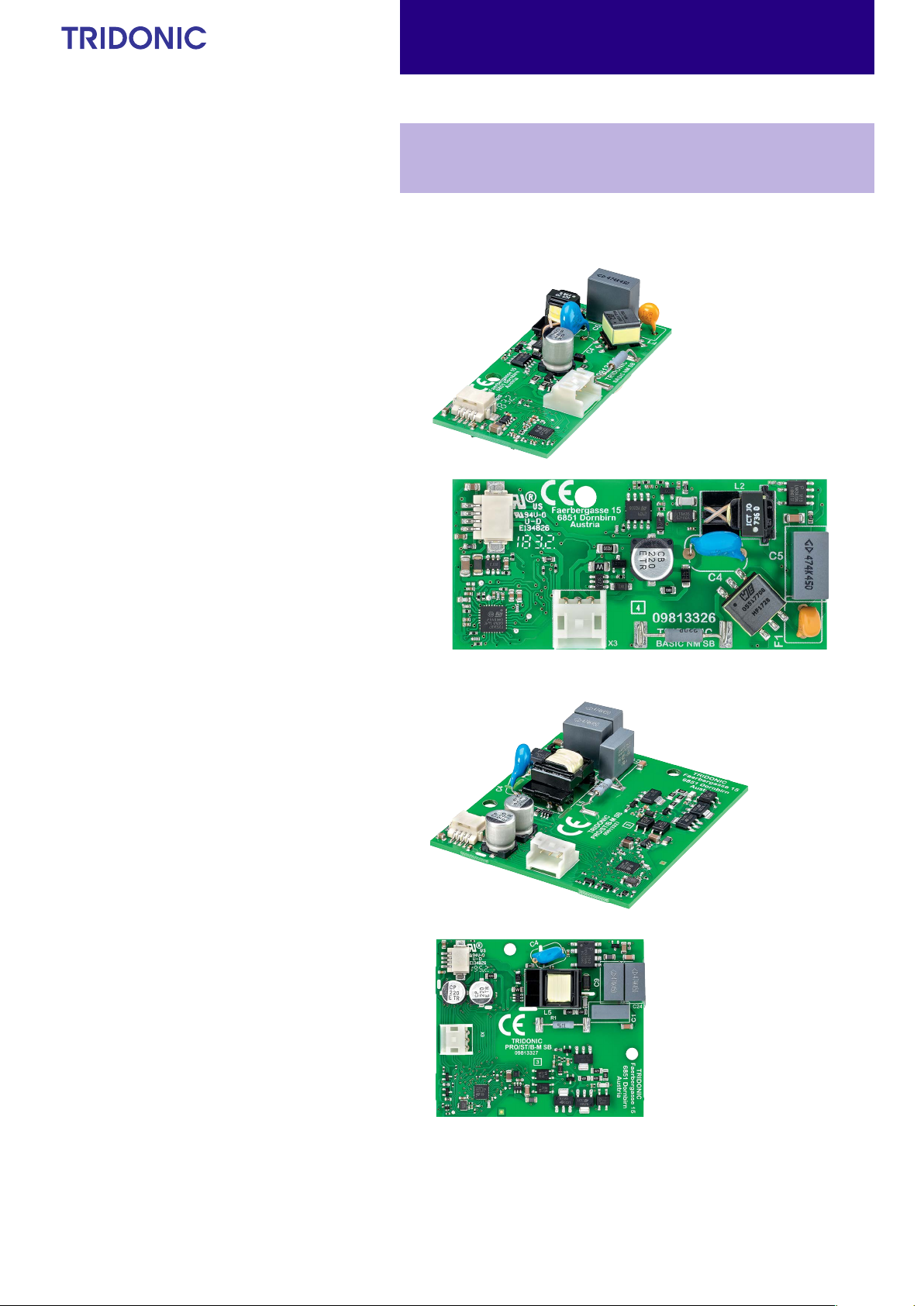
EM LED Light Engines
EM ready2apply NM 132 2 W PCB
EM ready2apply
È
Standards, page 5
EM R2A NM BASIC
Data sheet 01/21-EM088-2
Subject to change without notice. Information provided without guarantee.
EM R2A NM ST/PRO
www.tridonic.com
1
EL
73.00
Emergency lighting units
EM LED Light Engines
EM ready2apply NM 132 2 W PCB
EM ready2apply
Technical data
Rated supply voltage AC 220 – 240 V
Input voltage range AC (tolerance for
safety)
Input voltage range AC (tolerance for
performance)
Mains frequency 50 / 60 Hz
Overvoltage protection 320 V (for 48 h)
Time to light (emergency operation) < 0.5 s from detection of emergency event
Output current tolerance ± 5 %
Low frequency current ripple ± 5 %
Ambient temperature range ta +5 ... +45 °C
Max. casing temperature tc (C10) +60 °C
Mains voltage changeover threshold according to EN 60598-2-22
Nominal life-time 50,000 h
EoF
I
198 – 264 V
198 – 254 V
1
26.00±0.20
33.25±0.20
EM R2A NM BASIC
26.00±0.20
+
C10
62.50±0.20
73.00±0.20
ø
tc
ø4
±0.20
3.58±0.20
tc
C10
+
3.70±0.20
4.20±0.20
ø
22.20±0.20
EM R2A NM ST/PRO
Ordering data
Type
EM R2A BASIC NM 132 2W PCB 89800680 3 h 2 15 pc(s). 480 pc(s). 0.019 kg
EM R2A ST NM 132 2W PCB 89800681 3 h 2 15 pc(s). 480 pc(s). 0.031 kg
EM R2A PRO NM 132 2W PCB 89800682 3 h 2 15 pc(s). 480 pc(s). 0.031 kg
Article
number
Rated
duration
Number
of cells
Packaging,
carton
Packaging,
pallet
Weight
per pc.
Specific technical data
Type
Normal operation
EM R2A BASIC NM 132 2W PCB 2 3 16 mA 5 mA 2.5 W 0.6 W 0.63 – – –
EM R2A ST NM 132 2W PCB 2 3 20 mA 10 mA 2.5 W 0.6 W 0.63 – – –
EM R2A PRO NM 132 2W PCB 2 3 20 mA 10 mA 2.5 W 0.6 W 0.63 – – –
Emergency operation
EM R2A BASIC NM 132 2W PCB 2 3 – – – – 126 mA 12 V 1.50 W
EM R2A ST NM 132 2W PCB 2 3 – – – – 126 mA 12 V 1.50 W
EM R2A PRO NM 132 2W PCB
y
Number of
battery cells
2 3
Rated
duration
Mains current
(230 V, 50 Hz) non-maintained
operation
Charging Charger off Charging Charger off
– – – –
Mains power
(230 V, 50 Hz) non-maintained
operation
Typ. λ (at
230 V, 50 Hz,
charging)
Typ .
output
current
126 mA 12 V 1.50 W
Typ .
output
voltage
Output power
Data sheet 01/21-EM088-2
Subject to change without notice. Information provided without guarantee.
www.tridonic.com
2
Product description
• Bezel and lenses for the EM ready2apply PCB
• Status LED and test switch included
• Integrated LED module with heat sink
• Click-in multi lens option
• Anti-panic, escape route and spot illumination
• Simple connection with plug-in system
Emergency lighting units
EM LED Light Engines
LED+LENS KIT
General
SORIES
ACCES-
Product description
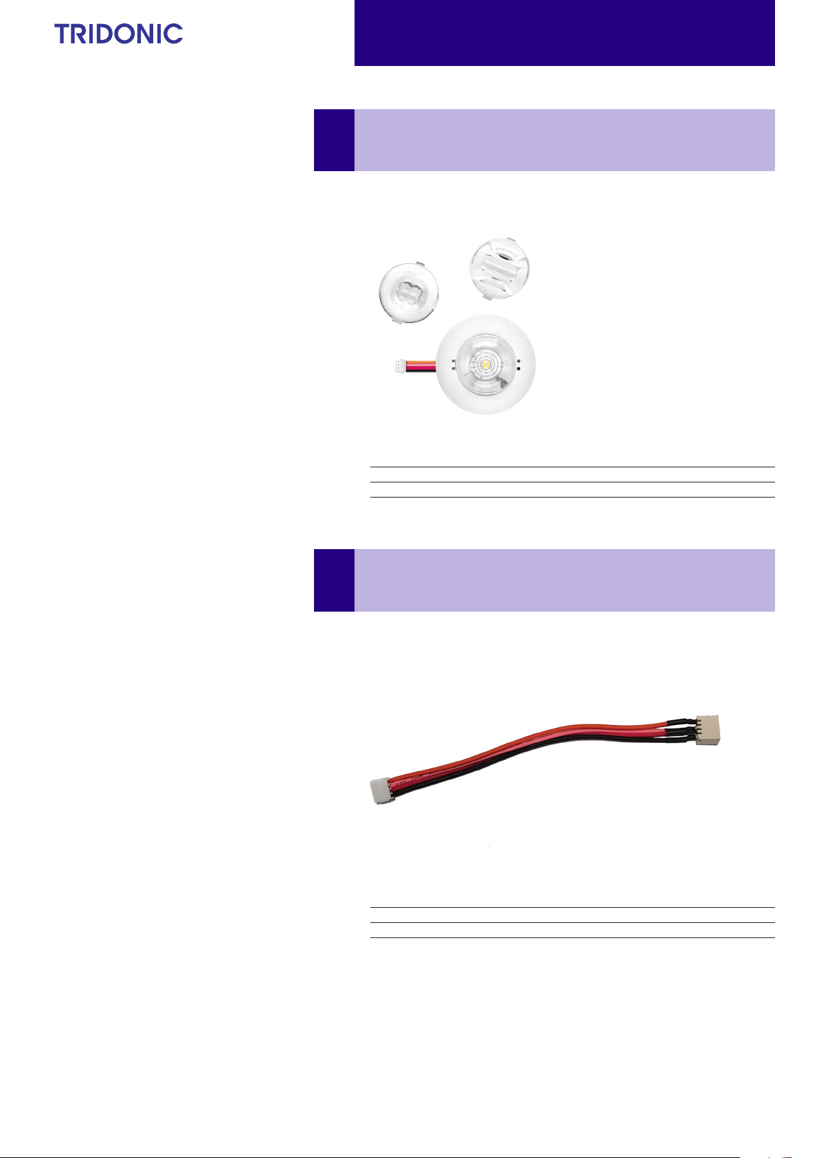
• Extension cable for EM LED+LENS KIT
• Cable length 100 mm
• 4-pole connection
Ordering data
Type Article number Packaging, carton Weight per pc.
EM R2A NM LED+LENS KIT 40mm 89800684 15 pc(s). 0.04 kg
Connection Cable EM R2A LED
General
SORIES
ACCES-
Data sheet 01/21-EM088-2
Subject to change without notice. Information provided without guarantee.
Ordering data
Type Article number Packaging, carton Weight per pc.
EXTENSION CABLE EM R2A LED 100mm 28002676 3,000 pc(s). 0.002 kg
www.tridonic.com
3

ACCES-
Product description
• High-temperature LiFePO4 cells for use with emergency lighting
units
• Up to 8-year design life
• 3-year guarantee from delivery date
Properties
• Environmental friendly technology
• High energy density
• Low profile cross-section with removable end caps
• Constant high-temperature operation
• Good charging properties at high temperature
• Electronic thermal battery management
• High energy maintenance of the charged battery
• Long shelf life
• Integrated electronics
• Safety features incorporated
• Certified quality manufacturer
• In various configurations
• Simple connection with plug-in system
• With polycarbonate fixing caps
• Suitable for emergency lighting equipment as per
IEC 60598-2-22
Emergency lighting units
EM LED Light Engines
LiFePO4 Accus 1.5 – 9.0 Ah
Lithium Iron Phosphate cells (LiFePO4)
SORIES
Ordering data
Type
LiFePO4 cells – stick, 1.5 – 9.0 Ah
Accu-LiFePO4 3.0 Ah 2A CON 28002318 1 x 2 3.0Ah 5 pc(s). 25 pc(s). 0.108 kg
LiFePO4 cells – side by side, 3.0 – 9.0 Ah
Accu-LiFePO4 3.0 Ah 2B CON 28002319 2 x 1 3.0Ah 5 pc(s). 25 pc(s). 0.100 kg
Articlenumber
Number
of cells
Capacity
Packaging,
carton
Packaging,
outer box
Weight per
pc.
Data sheet 01/21-EM088-2
Subject to change without notice. Information provided without guarantee.
www.tridonic.com
4

Emergency lighting units
12
3
EM LED Light Engines
1. Standards
according to EN 50172
EN 55015
EN 60068-2-6
according to EN 60068-2-30
EN 61000-3-2
EN 613 47-1
EN 613 47-2-7
EN 613 47-2-13
EN 61547
EN 62384
2. Thermal data
2.1 Expected life-time
Average life-time 50,000 hours under rated conditions with a failure rate of
less than 10 %. Average failure rate of 0.2 % per 1000 operating hours.
Expected life-time
Type
EM R2A
2.2 Storage conditions
ta 25 °C 30 °C 40 °C
life-time > 50,000 h 50,000 h 50,000 h
3.1 Wiring type and cross-section
Wiring PRO:
Mains (N, L): blue, brown
DALI (DA, DA): orange, orange
Wiring SELFTEST:
Mains (N, L): blue, brown
Rest: orange, orange
Wiring BASIC:
Mains (N, L): blue, brown
3.2 Lens assembly
• Wear gloves when mounting the lens
• Take care of the mounting direction of the escape route lens
• Use screwdriver for replacing/removing lens
1. + 2. Push lens clips with screwdriver via openings on both sides
3. Remove lens
• Humidity 45 % up to max. 85 %,
not condensed
(max. 56 days/year at 85 %)
• Storage time / temperature: max. 6 months at -20 °C up to +45 °C
(< 3 months at +45 °C)
Note: The devices have to be within the specified temperature range (ta)
before they are operated.
3. Installation / Wiring
DALIMains
EM R2A PCB
Indication LED + LED
EM R2A BASIC version: Green indication LED
EM R2A ST/PRO version: Green / Red indication LED
Battery
4. Mechanical data
4.1 Battery connection
Battery pack end termination
Compact 3-pole connector providing safe battery connection
4.2 Fixing of PCB
For fixing the PCB in the luminaire housing use 1 x M4 self tapping screw for
EM R2A BASIC variant and 2 x M4 self tapping screw for EM R2A ST/PRO
variants in combination with an moulded boss in polycarbonate or a washer.
Ensure that the mains connector is on the bottom side of the PCB. Therefore
fix the PCB to the luminaire housing with a spacer (made of a non-conductive material e.g. plastic).
The max. torque is 1.6 Nm.
Data sheet 01/21-EM088-2
Subject to change without notice. Information provided without guarantee.
www.tridonic.com
5

5. Electrical data
5.1 Maximum loading of automatic circuit breakers
Emergency lighting units
EM LED Light Engines
Automatic circuit breaker type C10 C13 C16 C20 B10 B13 B16 B20 Inrush current
Installation Ø 1.5 mm
EM R2A 180 260 260 260 90 130 130 130 10 A 120 μs
2
1.5 mm
2
2.5 mm
2
4 mm
2
1.5 mm
2
1.5 mm
2
2.5 mm
2
4 mm
2
I
max
5.2 Harmonic distortion in the mains supply (at 230 V / 50 Hz and 2-cell maintained charging) in %
THD 3. 5. 7. 9. 11.
EM R2A < 75 < 62 < 33 < 19 < 18 < 13
6. Functions
Functional test
Functional tests are carried out for 5 seconds on a weekly basis under the
6.1 BASIC
control of the Micro controller. Initiation and timing of these tests is set during the commissioning of the luminaire.
6.1.1 Status indication
Duration test
The indication LED is integrated in the bezel. A green LED indicates that char-
A full duration test is carried out yearly to check the capacity of the batteries.
ging current is flowing into the battery.
LED current: 9 mA
The battery is protected against operation at excessive temperatures (char-
For a full description of commissioning and test features please refer to
application notes.
ging stops and indication LED turns o when battery cell temperature < 0 °C or
> 60 °C).
Test switch
The test switch is integrated in the bezel. It can be used to to:
6.1.2 Test switch
The test switch is integrated in the bezel. To execute a function test press the
• Initiate a 5 seconds function test: press 200 ms < T < 1 s
• Execute function test as long as switch pressed: press > 1 s
• Reset selftest timer (adjust local timing): press > 10 s
test switch > 1 s.
time
6.2 SELFTEST
6.2.1 Status indication
The indication LED is integrated in the bezel. The system status is indicated
by a bi-colour LED.
LED current: 9 mA
LED indiction Status Comment
Permanent green System OK AC mode
Fast flashing green
(0,1 sec on – 0,1 sec o)
Slow flashing green
(1 sec on – 1 sec o)
Red LED on Load failure Open circuit / Short circuit / LED failure
Slow flashing red
(1 sec on – 1 sec o)
Fast flashing red
(0,1 sec on – 0,1 sec o)
Double pulsing green DALI Inhibit Switching into DALI inhibit mode via controller
Binary transmission of address
via green/red LED
Green and red o DC mode Battery operation (emergency mode)
Function test
underway
Duration test
underway
Battery failed the duration test or function
Battery failure
Charging failure Incorrect charging current
Address
identification
test / Battery is defect or deep discharged /
Incorrect battery voltage / Battery is outside of
its temperature range for charging (0 – 60 °C)
During address identification mode
6.2.2 Testing
Commissioning test
A full commissioning test is carried out automatically after permanent connection of the supply for 5 days. The easy commissioning feature will set the
initial test day and time to ensure random testing of units.
Test SwitchStatus LED
1,5 mm
Timer reset functionality
The timer for function and duration test can be set to a particular time of the
day by either pressing the test switch for longer than 10 seconds or cycling
the unswitched line supply 5 times within 1 minute. The timer adjustment
will enable the test start time to be defined manually at time in day when the
timer was reset. It will also disable the adaptive test algorithm thereby forcing the unit to perform the test at the same time rather than it being defined
by the adaptive algorithm. This function will only work provided the interval
time is greater than zero (automatic test mode enabled). The delay timer
value set when the unit was commissioned will be reloaded in order to randomise the tests between adjacent units.
Rest mode
Initiate the rest mode by applying a short pulse of between 9.5 V
22.5 V
DC in amplitude for a period of between 150 ms and 1.0 s. Apply this to
the terminals marked “Rest” after the mains supply has been disconnected
and whilst the module is in emergency operation.
Terminals are not sensitive to polarity.
After a mains reset the EM R2A ST exits the rest mode. The EM R2A ST
supports the re-light function.
Pulse/Mode Standby Emergency Rest
150 – 1,000 ms Inhibit Rest –
1,001 – 2,000 ms Cancel inhibit – re-light
DC and
Data sheet 01/21-EM088-2
Subject to change without notice. Information provided without guarantee.
www.tridonic.com
6

Emergency lighting units
EM LED Light Engines
6.3 PRO
6.3.1 Status indication
The indication LED is integrated in the bezel. System status is indicated by a
bi-colour LED and by a DALI status flag.
LED current: 9 mA
LED indiction Status Comment
Permanent green System OK AC mode
Fast flashing green
(0,1 sec on – 0,1 sec o)
Slow flashing green
(1 sec on – 1 sec o)
Red LED on Load failure Open circuit / Short circuit / LED failure
Slow flashing red
(1 sec on – 1 sec o)
Fast flashing red
(0,1 sec on – 0,1 sec o)
Double pulsing green DALI Inhibit Switching into DALI inhibit mode via controller
Binary transmission of address
via green/red LED
Green and red o DC mode Battery operation (emergency mode)
Function test
underway
Duration test
underway
Battery failed the duration test or function
Battery failure
Charging failure Incorrect charging current
Address
identification
test / Battery is defect or deep discharged /
Incorrect battery voltage / Battery is outside of
its temperature range for charging (0 – 60 °C)
During address identification mode
6.3.2 Testing
DALI Control
A DALI command from a suitable control unit can be used to initiate function and duration tests at individually selected times. Status flags are set for
report back and data logging of results.
When a DALI bus has not been connected or when a DALI bus is connected
but the DALI default DELAY and INTERVAL times have not been re-set by
sending appropriate DALI commands, then the EM R2A PRO will conduct
self-tests in accordance with the default times set within the EEPROM .
These default times are factory pre-set, in accordance with the DALI standard EN 62386-202, to conduct an automatic function test every 7 days and a
duration test every 52 weeks. Since the DELAY time is factory pre-set to
Zero, all units are tested at the same time. Test times can be changed with a
command over the DALI bus.
The DELAY and INTERVAL time values must be re-set when the emergency
system test times are to be scheduled by a DALI control and monitoring
system.
Note that once the default values have been set to Zero, tests will only be
conducted following a command from the control system. If the DALI bus is
disconnected the EM R2A PRO does not revert to self-testing mode.
Duration test
The time of day and frequency of the duration test can be set by the DALI
controller. The default setting is a duration test conducted every 52 weeks.
For 2 h operation:
The first commissioning duration test has a time of 120 minutes, subsequent through life tests are conducted for 90 minutes. When the battery is
changed or disconnected and re-connected the unit will next conduct a 120
minute test.
Test switch
The test switch is integrated in the bezel. It can be used to to:
• initiate a 5 seconds function test: press 200 ms < T < 1 s
• execute function test as long as switch pressed: press > 1 s
• reset selftest timer (adjust local timing): press > 10 s
Timer reset functionality
The timer for function and duration test can be set to a particular time of the
day by either pressing the test switch for longer than 10 seconds or cycling
the unswitched line supply 5 times within 1 minute. The timer adjustment
will enable the test start time to be defined manually at time in day when the
timer was reset. It will also disable the adaptive test algorithm thereby forcing the unit to perform the test at the same time rather than it being defined
by the adaptive algorithm. This function will only work provided the interval
time is greater than zero (automatic test mode enabled). The delay timer
value set when the unit was commissioned will be reloaded in order to randomise the tests between adjacent units.
Prolong time
Prolong time can be set by the DALI controller. This is the delay time
between return of the mains supply and the end of the emergency operation.
The default prolong time is set as 0 minutes as specified within the DALI
standard. Indicator LED will stay off for the duration of the prolong time.
Rest Mode
Rest mode can be initiated by the DALI controller. The appropriate command should be sent after the mains supply has been disconnected and
whilst the module is in emergency operation. After a mains reset the EM R2A
PRO exits the rest mode. EM R2A PRO supports the re-light command via
the DALI bus.
Max. rest mode duration: 21 days from fully charged battery
DALI Controller
DALI controllers and hardware/software solutions are available from
Tridonic. Please refer to the Lighting controls section.
Note: If the battery is connected the DALI communication is only possible
after power reset.
Commissioning
After installation of the luminaire and initial connection of the mains supply
and battery supply to the EM R2A PRO the unit will commence charging the
batteries for 20 hours (initial charge). Afterwards the module will conduct a
commissioning test for the full duration. The 20 hours recharge occurs also if
a new battery is connected or the module exits the rest mode condition. The
following automatic commissioning duration test is only performed when a
battery is replaced and fully charged (after 20 hrs) and the interval time is
not set to zero, otherwise the system is expected to perform the testing.
Functional test
The time of day and frequency of the 5 seconds function test can be set by
the DALI controller. The default setting is a 5 seconds test on a weekly basis.
Data sheet 01/21-EM088-2
Subject to change without notice. Information provided without guarantee.
www.tridonic.com
7

7. Battery data
7.1 Battery charge / discharge
EM R2A BASIC/ST/PRO 3 h
Emergency lighting units
EM LED Light Engines
Device
configuration
Article no. 89800680 / 89800681 / 89800682
Cells 2 cells
Duration
Initial 20 h
Battery charge
time
Typ. charge current
Mains power
consumption
Discharge current at 3.2 V (nominal) 625 mA
Max. charge voltage 3.55 – 3.65 V
End of discharge voltage 2.6 – 2.7 V
1
Automatic recharge when battery voltage falls below 3.4 V. Charger o (0 mA) when battery voltage exceeds 3.6 V.
Note: Battery protected against operation at excessive temperatures (charging stopped when battery cell temperature < 0 °C or > 60 °C)
Recharge 12 h
Trickle charge continuously and battery voltage controlled
Initial charge 290 mA
Recharge 290 mA
1
Trickle charge 290 mA / 0 mA
Initial charge < 1.095 W
Recharge < 1.095 W
Trickle charge < 1.095 W / 0 W
EM R2A BASIC/ST/PRO
3 h
7.2 Accu-LiFePO4
1.5 Ah
International designation 18650
Battery voltage/cell 3.2 V
Cell type 18650
Case temperature range to ensure
4 years design life +55 °C
6 years design life +45 °C
8 years design life +35 °C
Max. short term temperature (reduced life-time) 70 °C
Max. number discharge cycles 50 cycles total
Max. storage time 12 months
at +5 °C to +25 °C
Comply with UN 38.3 and IEC 62133 (safety testing) protected against over
charge, over discharge, charging at excessive temperatures, short-circuit and
over current.
8. Miscellaneous
8.1 Black Box data recording
Recording of several parameters only accessable for Tridonic.
8.2 Additional information
Additional technical information at www.tridonic.com → Technical Data
Guarantee conditions at www.tridonic.com → Services
Life-time declarations are informative and represent no warranty claim.
Data sheet 01/21-EM088-2
Subject to change without notice. Information provided without guarantee.
www.tridonic.com
8
 Loading...