

Tridonic DALI basicDIM DGC Product Manual

luxCONTROL
DALI basicDIM DGC
Product Manual

Product manual basicDIM DGC | 07-2018 | 1.9 | en
Table of Contents
c
2 / 48
...
1. Scope of documentation 3
1.1. Copyright . . . . . . . . . . . . . . . . . . . . . . . . . . . . . . . . . . . . . . . . . . . . . . . . . . . . . . . . . . . . . . . . . . . . . . . . . . . . . . . . . . . . . . . . . . . . . . . . . . . . . . . . . . . . . . . . . 3
1.2. Imprint . . . . . . . . . . . . . . . . . . . . . . . . . . . . . . . . . . . . . . . . . . . . . . . . . . . . . . . . . . . . . . . . . . . . . . . . . . . . . . . . . . . . . . . . . . . . . . . . . . . . . . . . . . . . . . . . . . . 3
2. Safety instructions 4
2.1. Intended use . . . . . . . . . . . . . . . . . . . . . . . . . . . . . . . . . . . . . . . . . . . . . . . . . . . . . . . . . . . . . . . . . . . . . . . . . . . . . . . . . . . . . . . . . . . . . . . . . . . . . . . . . . . . . 4
2.2. Dangers associated with the operation of the system . . . . . . . . . . . . . . . . . . . . . . . . . . . . . . . . . . . . . . . . . . . . . . . . . . . . . . . . . . . . . . . . . . . . . . 4
3. Product description 5
3.1. General information . . . . . . . . . . . . . . . . . . . . . . . . . . . . . . . . . . . . . . . . . . . . . . . . . . . . . . . . . . . . . . . . . . . . . . . . . . . . . . . . . . . . . . . . . . . . . . . . . . . . . . . 5
3.2. Main applications . . . . . . . . . . . . . . . . . . . . . . . . . . . . . . . . . . . . . . . . . . . . . . . . . . . . . . . . . . . . . . . . . . . . . . . . . . . . . . . . . . . . . . . . . . . . . . . . . . . . . . . . . 5
3.3. Hardware / Connections / Specifications . . . . . . . . . . . . . . . . . . . . . . . . . . . . . . . . . . . . . . . . . . . . . . . . . . . . . . . . . . . . . . . . . . . . . . . . . . . . . . . . . . . 6
3.4. System description . . . . . . . . . . . . . . . . . . . . . . . . . . . . . . . . . . . . . . . . . . . . . . . . . . . . . . . . . . . . . . . . . . . . . . . . . . . . . . . . . . . . . . . . . . . . . . . . . . . . . . . 6
4. Installation 7
5. Functions 10
5.1. Basic functions . . . . . . . . . . . . . . . . . . . . . . . . . . . . . . . . . . . . . . . . . . . . . . . . . . . . . . . . . . . . . . . . . . . . . . . . . . . . . . . . . . . . . . . . . . . . . . . . . . . . . . . . . . 10
5.2. Constant light control . . . . . . . . . . . . . . . . . . . . . . . . . . . . . . . . . . . . . . . . . . . . . . . . . . . . . . . . . . . . . . . . . . . . . . . . . . . . . . . . . . . . . . . . . . . . . . . . . . . . 23
5.3. Presence control . . . . . . . . . . . . . . . . . . . . . . . . . . . . . . . . . . . . . . . . . . . . . . . . . . . . . . . . . . . . . . . . . . . . . . . . . . . . . . . . . . . . . . . . . . . . . . . . . . . . . . . . . 27
5.4. Remote control . . . . . . . . . . . . . . . . . . . . . . . . . . . . . . . . . . . . . . . . . . . . . . . . . . . . . . . . . . . . . . . . . . . . . . . . . . . . . . . . . . . . . . . . . . . . . . . . . . . . . . . . . . 31
6. Room profiles 32
6.1. Room profile 1 Individual room . . . . . . . . . . . . . . . . . . . . . . . . . . . . . . . . . . . . . . . . . . . . . . . . . . . . . . . . . . . . . . . . . . . . . . . . . . . . . . . . . . . . . . . . . . . 32
6.2. Room profile 2 Classroom . . . . . . . . . . . . . . . . . . . . . . . . . . . . . . . . . . . . . . . . . . . . . . . . . . . . . . . . . . . . . . . . . . . . . . . . . . . . . . . . . . . . . . . . . . . . . . . . 35
6.3. Room profile 3 Corridor . . . . . . . . . . . . . . . . . . . . . . . . . . . . . . . . . . . . . . . . . . . . . . . . . . . . . . . . . . . . . . . . . . . . . . . . . . . . . . . . . . . . . . . . . . . . . . . . . . 38
6.4. Room profile 4 Restroom . . . . . . . . . . . . . . . . . . . . . . . . . . . . . . . . . . . . . . . . . . . . . . . . . . . . . . . . . . . . . . . . . . . . . . . . . . . . . . . . . . . . . . . . . . . . . . . . 41
6.5. Room profile 5 Free-standing luminaire (default) . . . . . . . . . . . . . . . . . . . . . . . . . . . . . . . . . . . . . . . . . . . . . . . . . . . . . . . . . . . . . . . . . . . . . . . . . 44
7. Status information 47
7.1. Green light Normal operation . . . . . . . . . . . . . . . . . . . . . . . . . . . . . . . . . . . . . . . . . . . . . . . . . . . . . . . . . . . . . . . . . . . . . . . . . . . . . . . . . . . . . . . . . . . . 47
7.2. Orange light Maintenance . . . . . . . . . . . . . . . . . . . . . . . . . . . . . . . . . . . . . . . . . . . . . . . . . . . . . . . . . . . . . . . . . . . . . . . . . . . . . . . . . . . . . . . . . . . . . . . 47
7.3. Red light Error . . . . . . . . . . . . . . . . . . . . . . . . . . . . . . . . . . . . . . . . . . . . . . . . . . . . . . . . . . . . . . . . . . . . . . . . . . . . . . . . . . . . . . . . . . . . . . . . . . . . . . . . . . 47
8. Reference list 48
8.1. Related documents . . . . . . . . . . . . . . . . . . . . . . . . . . . . . . . . . . . . . . . . . . . . . . . . . . . . . . . . . . . . . . . . . . . . . . . . . . . . . . . . . . . . . . . . . . . . . . . . . . . . . . 48
8.2. Downloads . . . . . . . . . . . . . . . . . . . . . . . . . . . . . . . . . . . . . . . . . . . . . . . . . . . . . . . . . . . . . . . . . . . . . . . . . . . . . . . . . . . . . . . . . . . . . . . . . . . . . . . . . . . . . . 48
8.3. Additional information . . . . . . . . . . . . . . . . . . . . . . . . . . . . . . . . . . . . . . . . . . . . . . . . . . . . . . . . . . . . . . . . . . . . . . . . . . . . . . . . . . . . . . . . . . . . . . . . . . 48

Product manual basicDIM DGC | 07-2018 | 1.9 | en
Scope of documentation
c
3 / 48
These operating instructions are valid for the basicDIM DGC.
TRIDONIC GmbH & Co KG is constantly striving to develop all its products. This means that there may be changes in form, equipment
and technology.
Claims cannot therefore be made on the basis of information, diagrams or descriptions in these instructions.
The latest version of these operating instructions is available on our home page at
http://www.tridonic.com/com/en/operating-instructions.asp
1.1. Copyright
This documentation may not be changed, expanded, copied or passed to third parties without the prior written agreement of
TRIDONIC GmbH & Co KG.
We are always open to comments, corrections and requests. Please send them to .info@tridonic.com
1.2. Imprint
Tridonic GmbH & Co KG
Färbergasse 15
6851 Dornbirn
Austria
T +43 5572 395-0
F +43 5572 20176
www.tridonic.com
...
I NOTICE
The basicDIM DGC is configured in the masterCONFIGURATOR software (V2.12. or later) and basicDIM DGC Programmer (see
"Reference list" at the end of this document).

Product manual basicDIM DGC | 07-2018 | 1.9 | en
Safety instructions
c
4 / 48
The instructions in this section have been compiled to ensure that operators and users of the basicDIM DGC from Tridonic are able to
detect potential risks in good time and take the necessary preventative measures.
The operator must ensure that all users fully understand these instructions and adhere to them. This device may only be installed and
configured by suitably qualified personnel.
2.1. Intended use
2.1.1. Proper use
Control module for the operation of DALI/DSI compatible luminaires. The device may only be used for this intended purpose.
2.1.2. Improper use
Outdoor use. Extensions and modifications to the product.
2.2. Dangers associated with the operation of the system
...
½ WARNING!
Improper use could result in injury, malfunction or damage to property.
It must be ensured that the operator informs every user of existing hazards.
½ DANGER!
Danger of electrocution
Disconnect the power to the entire lighting system before working on the lighting system!
½ CAUTION!
Risk of damage caused by condensation
Prior to commissioning the system, wait until the control device is at room temperature and completely dry!
½ CAUTION!
Risk of damage caused by humidity
Only use the control device in dry rooms and protect it against humidity!
½ CAUTION!
Electromagnetic compatibility (EMC)
Although the Tridonic control device meets the stringent requirements of the appropriate directives and standards on
electromagnetic compatibility, it could potentially interfere with other devices under certain circumstances!
Product manual basicDIM DGC | 07-2018 | 1.9 | en
Product description
c
5 / 48
3.1. General information
The basicDIM DGC is a digital controller in the comfortDIM product range that can be used to control the control gear of a DALI group
collectively.
The basic DIM DGC provides the basis for an easy-to-use and cost-effective lighting system with motion detection. When the sensor
detects movement it triggers an individually adjusted table motion detection profile in the control unit. As the amount of natural
ambient light changes the illuminance from the artificial lighting system is adjusted. The connected luminaires can be switched on and
off via momentary-action switch or remote control possible.
The DALI IN interface allows integration of the basicDIM DGC module also into a comfortDIM system.
The basicDIM DGC module has 5 preprogrammed profiles which can be selected using the basicDIM DGC Programmer. The profiles
can be adjusted to your application via the master CONFIGURATOR ( V2.12) software (see "Reference list" at the end of this
document).
If the basicDIM DGC module is used in the basic application, the CH2 can be used as control channel for controlling subordinate
basicDIM DGC modules (basic connection), so that the controlling and the subordinate basicDIM DGC modules can be programmed
and allocated to groups using the masterCONFIGURATOR software. Every single basicDIM DGC module can be allocated to only one
group and respond to the presence of up to five groups. For more detailed information please refer to the masterCONFIGURATOR
documentation (see "Reference list" at the end of this document).
3.2. Main applications
The DALI basicDIM DGC is designed for the following principal applications:
Individual offices_
Open-plan offices_
Training/presentation rooms_
Corridors, passage ways and garages
The basicDIM DGC either controls all the units on the DALI circuit or a DALI group. The basicDIM DGC is Multi-master
compatible, i.e. it can be used in conjunction with other DALI controllers in the comfortDIM product range. This allows
the basicDIM DGC to be addressed and grouped in the same way as DALI control gear and makes it easy to configure the
system. The basicDIM DGC is configured in the masterCONFIGURATOR software (V2.02. or later) (see "Reference list" at the
end of this document).
_
Product manual basicDIM DGC | 07-2018 | 1.9 | en
Product description
c
6 / 48
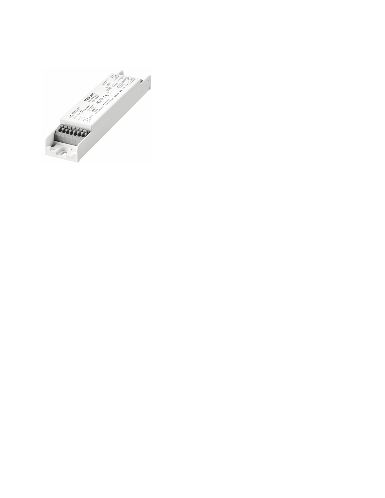
3.3. Hardware / Connections / Specifications
3.4. System description
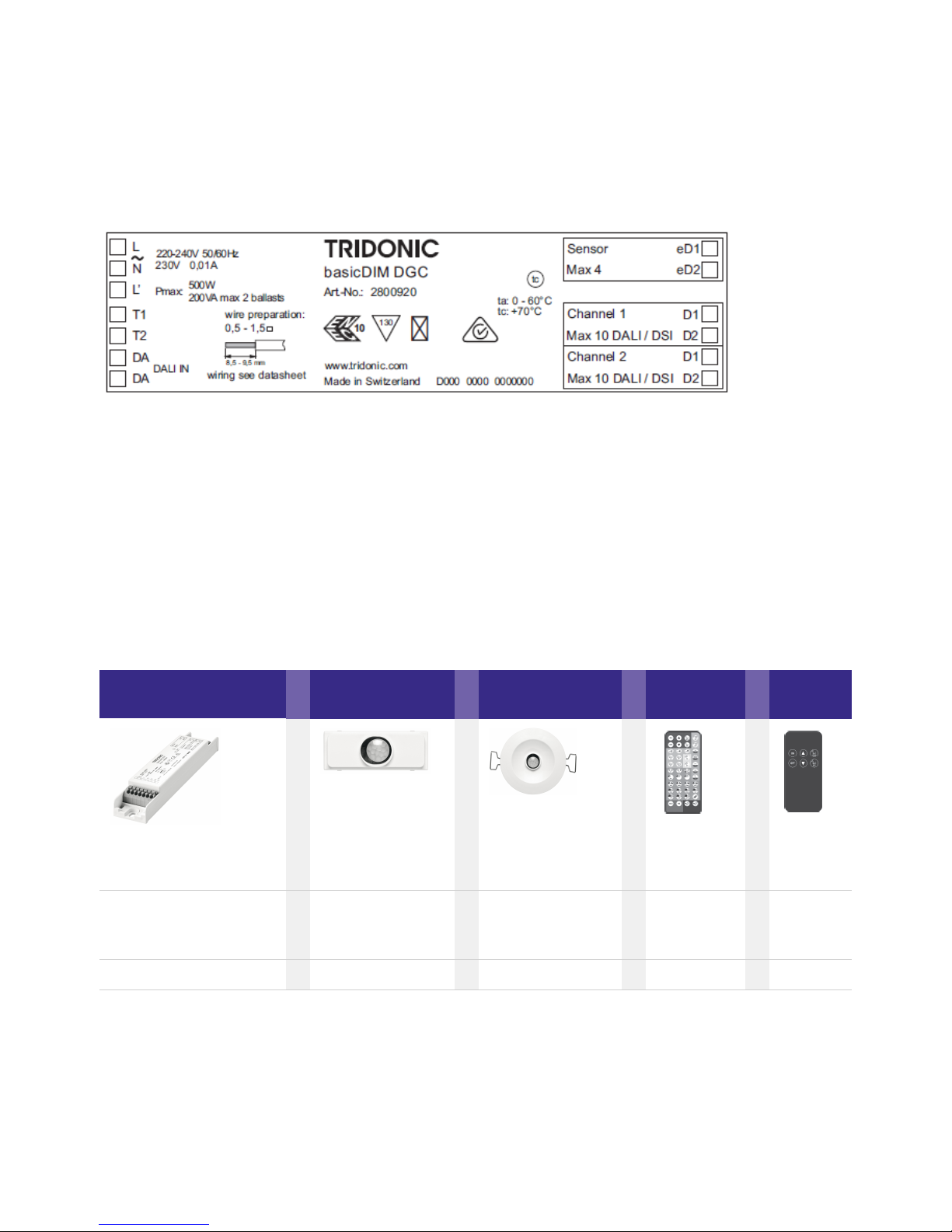
The DALI basicDIM DGC can be used as a single unit or in combination with basicDIM DGC 5DPI_14 sensors:
Digital controller
+ Sensor / Sensor +
Remote
control /
Remote
control
DALI basicDIM DGC basicDIM DGC Sensor
5DPI 14f inbuilt
basicDIM DGC Sensor
5DPI 14 rc remote
basicDIM DGC
Programmer
REMOTE-
CONTROL
IR6
(28000920) (28000933) (28000934) (28000646) (28000647)
...
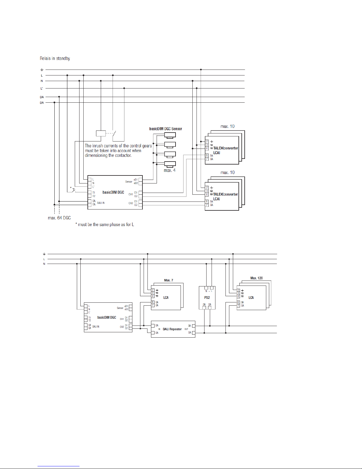
Supply: 230 V AC 50/60 Hz_
1 relay output L' (max. 500W/200VA)_
T1, T2 Terminals for the connection of two local 230 V keys_
DALI IN input_
Sensor connection for up to 4 basicDIM DGC sensors_
For up to 20 DSI or DALI ballasts (max. 10 per output channel)_

Product manual basicDIM DGC | 07-2018 | 1.9 | en
Installation
c
7 / 48
Product manual basicDIM DGC | 07-2018 | 1.9 | en
Installation
c
8 / 48
Wiring diagram basicDIM DGC with DALI PS1(2)
Use only in combination with DALI Repeater (86458401) and one of the following DALI supplies:
This combination can be used on CH1 and CH2.
DALI PS1 (24034323), 200 mA, max. 100 additional devices_
DALI PS2 (28000876), 240 mA, max. 120 additional devices_

Product manual basicDIM DGC | 07-2018 | 1.9 | en
Installation
c
9 / 48
...
I NOTICE
Installation
basicDIM DGC can be operated without sensor. For this, the motion sensor must be deactivated with the
masterCONFIGURATOR software.
_
DSI/DALI is not SELV. The installation instructions for mains voltage therefore apply._
The maximum cable length between the external switch and basicDIM DGC is 100 m._
The maximum cable length between the sensor and basicDIM DGC is 10 m._
A synchronous operation of DALI and DSI ballasts at the same control gear is not possible._
The output channels (for a cable cross-section of 1,5 m ) must not be exceeded 100 m.
2
_
If CH2 is used as link line, the maximum cable length must not exceed 100 m (at 1.5 mm ).
2
_
Any number of push to make switches may be connected in parallel to the inputs._
Do not connect standard switches to the input._
Please ensure that the detection range of the sensor lies in the lighting area of the controlled luminaires._
Heaters, fans, printers and copiers located in the detection zone may cause incorrect presence detection._
To avoid false readings, the sensor should be installed so there is no direct light from the lamp in the detection zone._
Sensor wires must be routed separately from the lamp wires and mains cables otherwise the lighting control system may
malfunction. If separate routing is not possible (for reasons of space) shielded lamp wires and mains cables must be used.
_

Product manual basicDIM DGC | 07-2018 | 1.9 | en
Functions
c
10 / 48
The DALI basicDIM DGC has the following functions and user interfaces:
5.1. Basic functions
5.1.1. PowerOn behaviour
The PowerOn behaviour determines the behaviour of the basicDIM DGC when .it is switched on and off The following commands are
transferred at PowerOn.
CH1 DALI CH1 eD CH2 DALI CH2 eD
PowerON
- -
the settings of the The adjustable parameters MIN LEVEL SET, SET MAX LEVEL are taken from basicDIM DGC.
5.1.2. Behaviour in normal operation
In normal operation the following parameters are transferred:
CH1 DALI CH1 eD CH2 DALI CH2 eD
Normal
operation
-
The eD-parameter QUERY TYPE CONTROL NUMBER checks whether an additional basicDIM DGC is connected to CH2 (which
corresponds to basic configuration).
If this is the case, the DALI IN port will be disabled.
Basic functions_
Constant light control by means of ambient light sensor_
Presence-based control by means of PIR motion sensor or presence detector_
Remote control via an infrared input for two different IR remote controls_
DTR0_
SET POWER ON LEVEL_
SET SYSTEM FAILURE LEVEL_
SET MIN LEVEL (adjustable)_
SET MAX LEVEL (adjustable)_
SET FADE TIME_
DTR0_
SET POWER ON LEVEL_
SET SYSTEM FAILURE LEVEL_
SET MIN LEVEL (adjustable)_
SET MAX LEVEL (adjustable)_
SET FADE TIME_
DAP_
QUERY LAMP
FAILURE
_
DAP_
QUERY LAMP
FAILURE
_
QUERY CONTROL TYPE
NUMBER
_
Product manual basicDIM DGC | 07-2018 | 1.9 | en
Functions
c
11 / 48
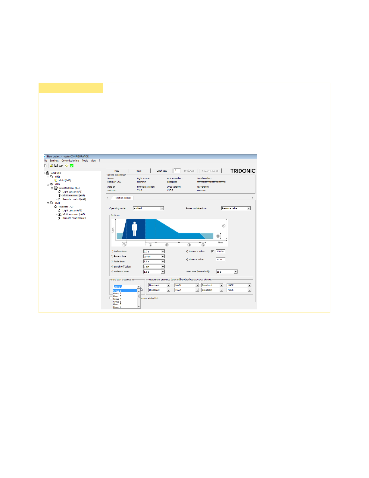
5.1.3. Mixed installation with DGC and MSensor
½ CAUTION!
Note the following, if you are using a mixed installation with DGCs and MSensors:
If the DGC is moved to group 1 (for example), it will still send its own presence as Broadcast by default.
If there is an MSensor in the same installation (for example in group 2), then group 2 will be triggered by the Broadcast signal sent
from the DGC.
To avoid this behaviour, make sure that the DGC is programmed to send its presence to the group that it is assigned to (in this
example group 1).
Product manual basicDIM DGC | 07-2018 | 1.9 | en
Functions
c
12 / 48
1.
2.
3.
5.1.4. DALI IN interface
connected to Disconnect all DGCs CH2
to Connect DALI USB CH2
configuration Switch mode of CH2
DALI IN interface is activated
The DALI IN interface allows integration of the basicDIM DGC module also into a comfortDIM or other Building Management Systems
(BMS). The following DALI commands are supported.
Supported DALI configuration commands
...
½ CAUTION!
By using the DGC in basic configuration (additional DGCs connected to CH2) DALI IN interface will be deactivated.
To activate the DALI IN interface DALI again, proceed as follows:
RESET_
STOREACTUALLEVELINTHEDTR_
STORETHEDTRASMAXLEVEL_
STORETHEDTRASMINLEVEL_
STORETHEDTRASFADETIME_
ADDTOGROUP_
REMOVEFROMGROUP_
STOREDTRASSHORTADDRESS_
ENABLEWRITEMEMORY_
TERMINATE_
DATATRANSFERREGISTER(DTR)_
INITIALISE_
RANDOMISE_
COMPARE_
WITHDRAW_
SEARCHADDRH_
SEARCHADDRM_
SEARCHADDRL_
PROGRAMSHORTADDRESS_
VERIFYSHORTADDRESS_
DATATRANSFERREGISTER1(DTR1)_
DATATRANSFERREGISTER2(DTR2)_
WRITEMEMORYLOCATION_

Product manual basicDIM DGC | 07-2018 | 1.9 | en
Functions
c
13 / 48
Reaction to DALI control commands at the DALI IN interface
DIRECT ARC POWER CONTROL (DAP)_
OFF_
UP / Down_
RECALL MAX LEVEL_
RECALL MIN LEVEL_
ON AND STEP UP_
GO TO SCENE_

Product manual basicDIM DGC | 07-2018 | 1.9 | en
Functions
c
14 / 48
Response to DALI query commands at the DALI IN interface
Command
Reaction basicDIM DGC
QUERY STATUS
According to DALI
QUERY CONTROL GEAR Response is always "Yes" (0xFF), independent of what control gear is connected to CH1/CH2
QUERY LAMP FAILURE Error bit is set if at least one connected device reports an error
QUERY LAMP POWER ON Answer is "yes" if at least one output channel is on
QUERY LIMIT ERROR According to DALI
QUERY RESET STATE According to DALI
QUERY MISSING SHORT ADDRESS According to DALI
QUERY VERSION NUMBER According to DALI
QUERY CONTENT DTR According to DALI
QUERY DEVICE TYPE According to DALI
QUERY PHYSICAL MINIMUM LEVEL According to DALI
QUERY CONTENT DTR1 According to DALI
QUERY CONTENT DTR2 According to DALI
QUERY ACTUAL LEVEL is Current nominal value of output channel 1 is answered (even if output channel 1 0% and
is output channel 2 > 0% ).
QUERY MAX LEVEL According to DALI
QUERY MIN LEVEL According to DALI
QUERY FADE TIME / FADE RATE Fade Time according to DALI Fade Rate always "8".
QUERY GROUPS 0-7 According to DALI
QUERY GROUPS 8-15 According to DALI
QUERY RANDOM ADDRESS (H) According to DALI
QUERY RANDOM ADDRESS (M) According to DALI

Product manual basicDIM DGC | 07-2018 | 1.9 | en
Functions
c
15 / 48
QUERY RANDOM ADDRESS (L) According to DALI
READ MEMORY LOCATION According to DALI
QUERY SHORT ADDRESS According to DALI
5.1.5. Switch
basicDIM DGC has two inputs (T1 and T2) for two external switches. Any number of switches can be connected in parallel to the
inputs (parallel connection of T1 and T2 possible).
Action
Reaction
Short press (<
500 ms)
ON/OFF (a short press activates lighting control, with this the switch like the AUTO key of the BasicDIM remote
control)
Long press (>
500 ms)
Dim up/down
A change in light value deactivates the lighting control temporarily. Lighting control is reactivated if the luminaire
switches on again automatically (when motion is detected) or if it is switched off and on manually.
The function can be edited with the basicDIM DGC Programmer or the masterCONFIGURATOR software (see
"Reference list" at the end of this document).
2 x short press Stores the currently measured light value as new setpoint of the lighting control (luminaire acknowledges by
flashing twice).
Depending on the profile selected, this function can be activated or deactivated. The function can be edited with
the basicDIM DGC Programmer or the masterCONFIGURATOR software (see "Reference list" at the end of this
document).
Different output channels are controlled, depending on the profile selected.
...
I NOTICE
Relay only responds to DALI command GO TO SCENE. Other commands are ignored by the Relay.
 Loading...