

Page 1
For questions or technical support call 888-422-3337 [email protected]
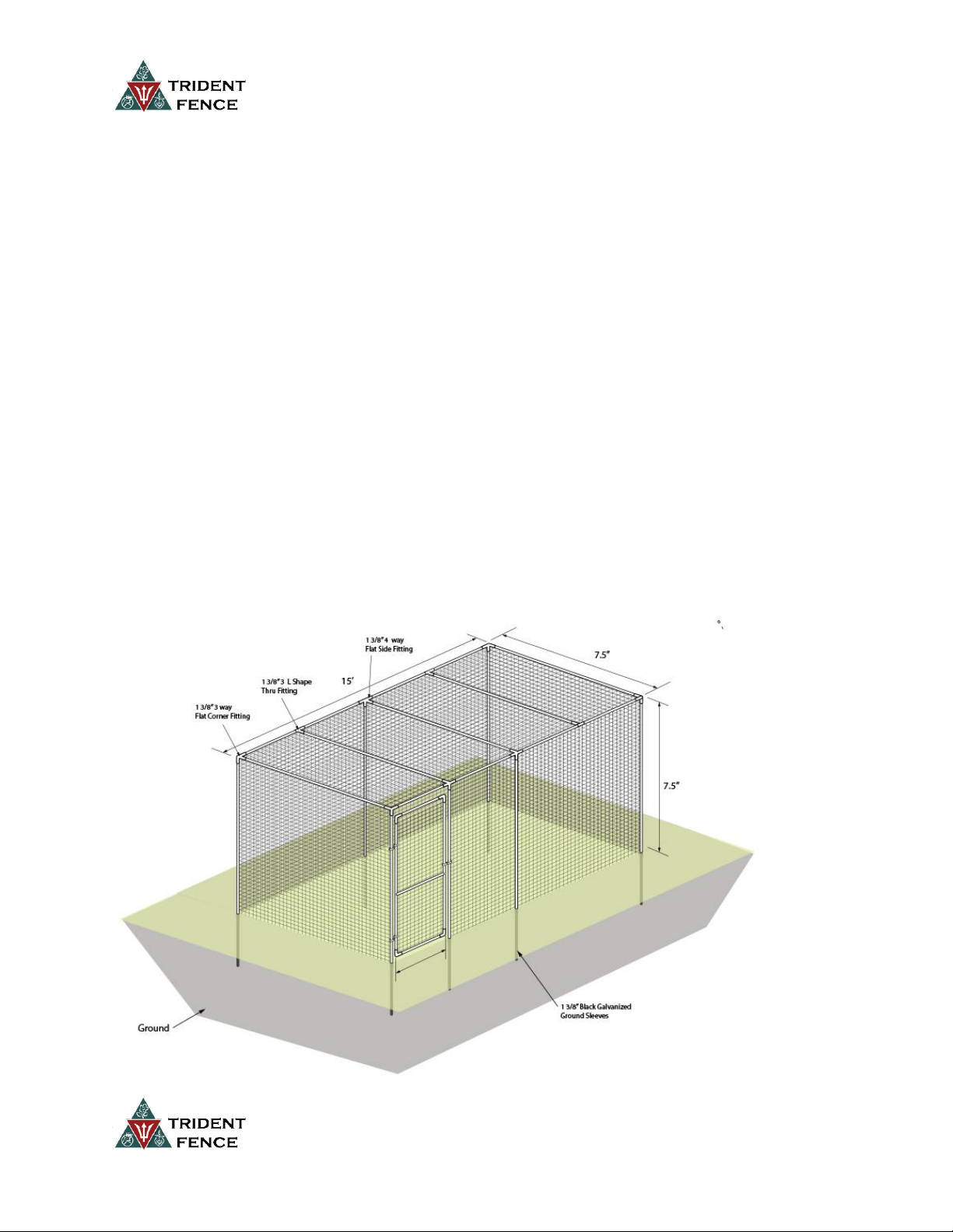
FENCE ENCLOSURE KIT WITH TOP 7.5’ x 15’
(Poly, Steel Hex, Welded)
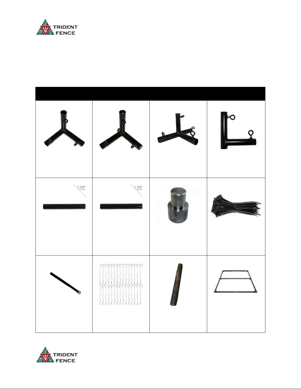
PARTS LIST
1 3/8" 3 Way Flat
Corner Fitting- Black
FP1002 Qty: 4
1 3/8" 3 Way Flat Thru
Fitting- Black
FP1007 Qty: 1
1 3/8" 4 Way Flat Side
Fitting- Black
FP1008 Qty: 2
1 3/8" L Shape Thru
Fitting- Black
FP1004 Qty: 3
1 3/8" x 87” Black
Powder Coated
Galvanized Steel Pipe
DE8353-087 Qty: 9
1 3/8" x 107 ¾” Black
Powder Coated
Galvanized Steel Pipe
DE8353-108 Qty: 7
1 3/8” Drive Cap for
Ground Sleeves
DE2810 Qty: 1
8” Heavy Duty Self
Locking Ties- 100 Pack
DE2854 Qty: 2
1 3/8” Black
Galvanized Ground
Sleeves
DE8195 Qty: 7
12” Kinked Galvanized
Ground Stakes- 30
Pack
DE2878 Qty: 1
100’ Fence Roll
(Poly, Steel Hex,
Welded)
DE1071 Qty: 1
3’ Wide Gate Assembly
Kit with Hardware
GA7003 Qty:1
Page 2
For questions or technical support call 888-422-3337 [email protected]
Step 1: Enclosure Top Assembly
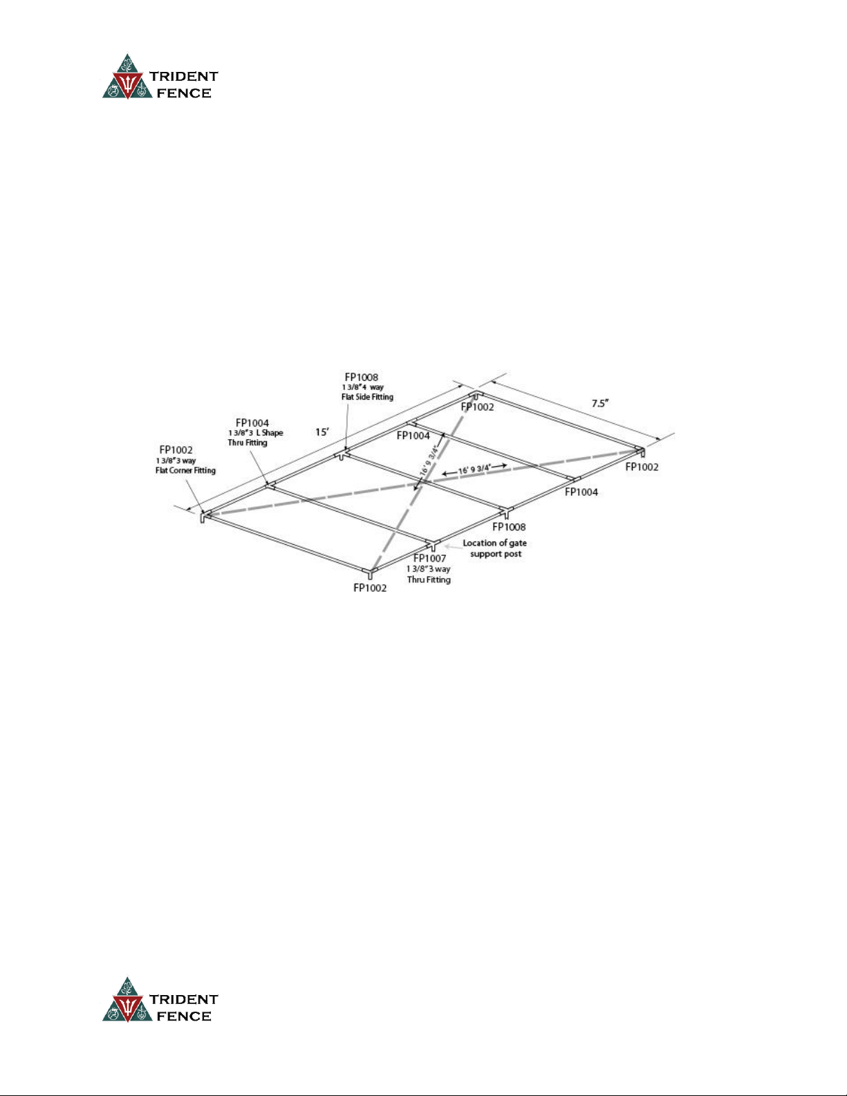
Parts Needed: (4) FP1002, (1) FP1007, (2) FP1008, (3) FP1004, (9) DE8353-087
Assemble the top frame as shown below using 87” long pipes for all connections. The FP1002 are used
on the corners. The FP1008 are used on the sides to attach the center support. The FP1004 are used to
attach the top supports. The FP1007 is used on the gate support post. Install this fitting on one of the
long sides of the enclosure 40 1/2” from the corner to the inside of the leg of the fitting that will become
the gate support post. (see diagram 1.)
DIAGRAM 1
Make sure your enclosure top is square by measuring the distances diagonally across the top. The
distance should be 16’ 9 3/4” in both directions as shown in diagram 1. If you plan on using the
assembled frame to mark the ground sleeves, move the frame into final position before squaring up the
top.
Be sure all the posts are all the way in the fittings and you have tightened all the thumbscrews.
Step 2: Ground Sleeve Installation
Parts Needed: (1) DE2810, (7) DE8195
Option 1: The finished top of the enclosure can be used to locate the correct placement for the ground
sleeves. Mark the placement for where the ground sleeves will be driven in the ground and move the
top of the enclosure to allow adequate clearance for driving the ground sleeves. Using the drive cap in
the top of each sleeve, drive the ground sleeves into the ground taking care to drive the sleeves plumb.
It is helpful to stop after every few hits and check the level of the sleeves when driving.
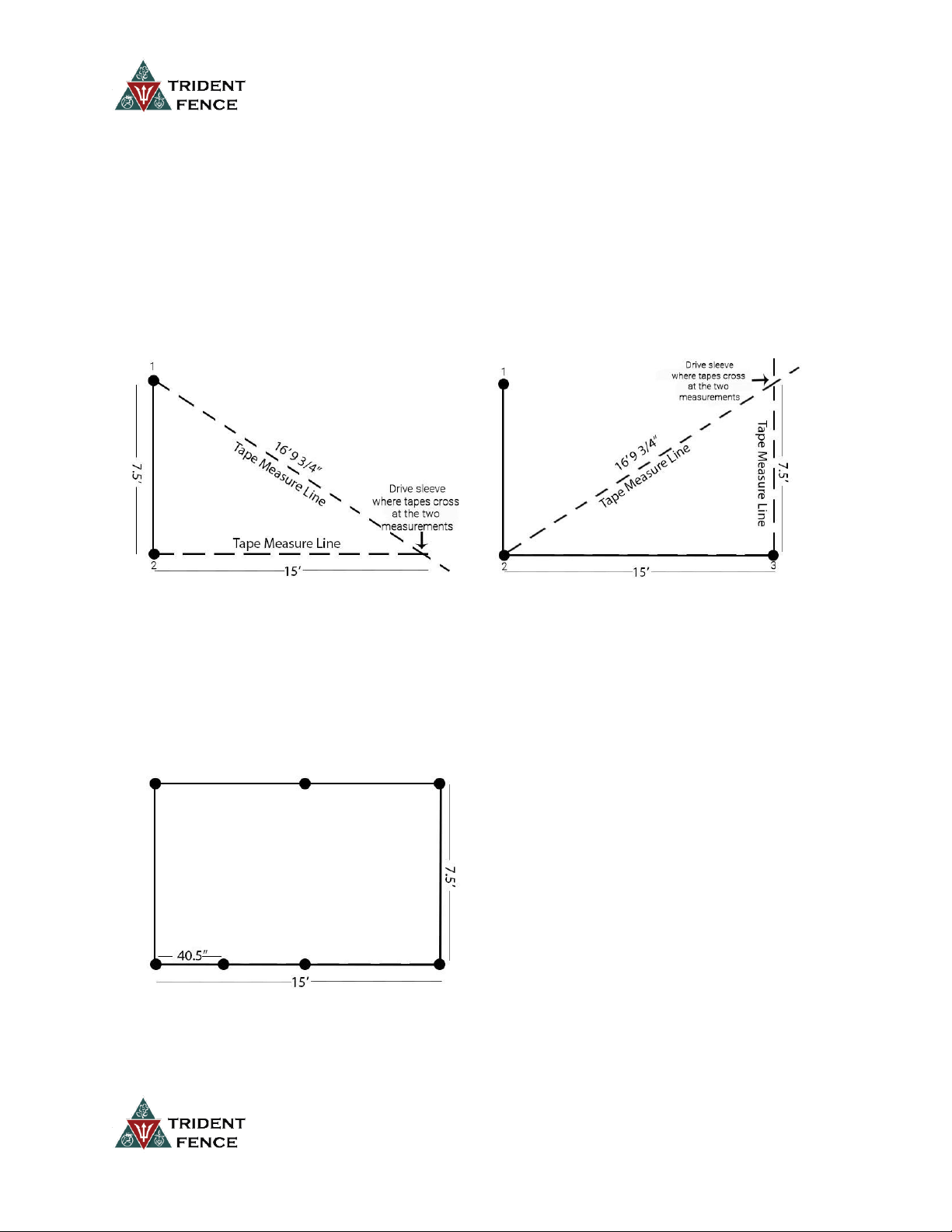
Option 2 (see diagram 2): If an existing garden bed or structure makes it impossible to mark the location
of the ground sleeves using the enclosure top you will need to make a series of measurements to ensure
Page 3
For questions or technical support call 888-422-3337 [email protected]
your sleeve placement is square. Use two tape measures to determine proper sleeve placement for the
four corners. All measurements are from the outside of the sleeve to the outside of the sleeve.
Determine the location and direction of one of the 7.5’ sides of your enclosure. Start by driving these
two sleeves into the ground. For the third corner, run two tape measures, one 15’ out from one corner
and one diagonally 16’ 9 ¾” from the other corner. Where these tapes cross at the two measurements is
where to drive the third sleeve. To determine the fourth corner, go up 7.5’ from corner 3 and diagonally
from corner 2 16’ 9 ¾”. Where these measurements cross is where to drive the fourth sleeve.
DIAGRAM 2 DIAGRAM 3
Once the corners are in place you can use a string line to determine the location of the remaining
sleeves on the 15’ sides of the enclosure. The gate latch post sleeve should be installed 40 1/2”
measuring from the outside of the corner posts to the outside of the post where the gate will be hung.
DIAGRAM 4
It will be helpful to have extra hands available to make this step easier.
Page 4
For questions or technical support call 888-422-3337 [email protected]
Step 3: Vertical Support Installation
Parts Needed: (7) DE8353-108
Slide the 7- 1 3/8" x 107 3/4" pipes into the ground sleeves
Step 4: Enclosure Top Frame Attachment
Option 1: Reassemble the top frame of the enclosure on top of the vertical support posts. It may be
possible to add the frame in sections rather than individual fittings and pipes.
Option 2: If you have enough hands, the entire frame may be dropped into place on top of the vertical
support posts.
Step 5: Assemble and Install Gate
Parts Needed: (1) GA7003
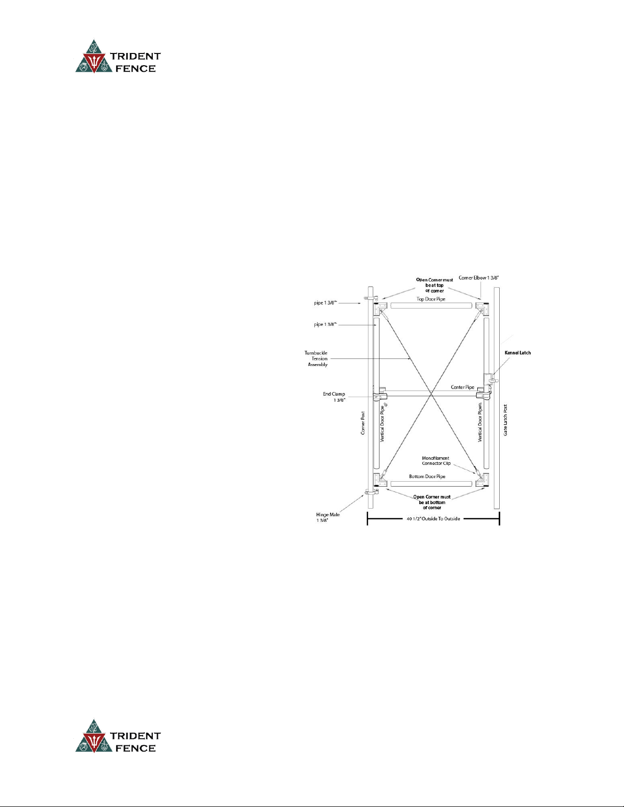
Gate Parts
(2) 33” x 1 3/8” Top/Bottom Horizontal Pipe
(1) 32” x 1 3/8” Center Horizontal Pipe
(2) 80” x 1 3/8” Vertical Gate Pipe
(2) 1 3/8” End Clamps
(2) Access Gate Turnbuckle Tension Assembly
(4) 1 3/8” Kennel Corner Elbows
(2) 1/8” Monofilament Clips
(2) 5/16” x2” Carriage Bolt
(4) 3/8” x 2” Carriage Bolt
(1) Kennel Latch
(2) 1 3/8” Kennel Hinge
(16) Self Tapping Screws
Assemble the gate using the included gate posts. The top and bottom horizontal gate frame posts will be
1 3/8" x 33". The 2 vertical gate posts are 1 3/8" x 80". Insert these posts into the 4 corner elbows
making sure the 80” post is in the side with the open end of the elbow. You should be able to see all the
way down the inside of the 80” pipe and out the other end after the elbows are installed.
Measure to find the center of your vertical sides and attach the center support post using the end
clamps and 5/16” x 2” carriage bolts.
Hook one of the turnbuckles located on the ends of the tension wire in the center hole of the corner
bracket on the top left of your gate. Fully extend the threads on the monofilament connector clip and
feed one tension wire through the opening on the clip. Loop the wire through the corner bracket on the
Page 5
For questions or technical support call 888-422-3337 [email protected]
bottom right. Feed the wire back through the connector clip. Take slack out of the wire and tighten the
connector clip securely. Repeat on other side. Measure diagonally from corner to corner to make sure
both directions are the same length. You can square up the gate if necessary by adjusting the
turnbuckles.
Install the male hinges loosely on the corner post closest to your gate support post. Attach the male
hinge at the base of the support post at the desired height and tighten the hinge. Drop gate panel onto
the male hinge and hold in place while attaching the top male hinge by sliding the male end into the
opening of the corner. Tighten down the bolts to lock the hinges in place.
Install kennel latch at the desired height on the gate panel. The latch should be installed so that it is
lifted up to open the gate.
Step 6: Attach Fence
Parts Needed: (1) DE1071, (2) DE2854, DE2878
Unroll the fence along the perimeter of the fence using zip ties to attach the fencing to the posts and
gate frame. Use approx. 7 ties per post. Run fencing along the top of the enclosure starting at one of the
7.5' wide sides and heading towards the back of the enclosure.
The entire perimeter of the enclosure base is staked down with kinked stakes every 2 feet.
 Loading...