

Page 1

i
3DImàge985
AGP
High Performance 3D/2D
GUI/Video Accelerator
User’s Guide
Page 2

i
NOTICE
The information in this document is subject to change in order to improve
reliability, design, or function without prior notice and does not represent a
commitment on the part of the company. In no event will the company be
liable for direct, indirect, special, incidental, or consequential damages
arising out of the use or the inability to use the product or documentation,
even if advised of the possibility of such damages. No part of this manual
may be reproduced or transmitted in any form or by any means without the
prior written permission of the company.
October 1997, Rev A
LIMITED WARRANTY
This product is warranted against defects in materials and workmanship
for a period of one year from the date of purchase. During the warranty
period, product determined by us to be defective in form or function will be
repaired or, at our option, replaced at no charge. This warranty does not
apply if the product has been damaged by accident, abuse, misuse, or as a
result of service or modification other than by the company.
This warranty is in lieu of any other warranty expressed or implied. In no
event shall the company be held liable for incidental or consequential
damages, such as lost revenue or lost business opportunities arising from
the purchase of this product.
Page 3

ii
TRADEMARK ACKNOWLEDGMENTS
Trident Microsystems, Inc. 1997. All rights reserved.
Trident Microsystems, Inc. 3DImàge985™ User’s Guide
Trident Microsystems, Inc. assumes no responsibility for the use of any circuit other than circuits embodied in an
Trident Microsystems, Inc. product. No other circuit patent licenses are implied.
AutoCAD and Autoshade are trademarks of Autodesk, Inc.
IBM is a registered trademark and PS/2 and OS/2 are trademarks of International Business Machines Corp.
Microsoft, Microsoft Windows, and Microsoft Word are registered trademarks of Microsoft Corp.
Pentium is a trademark of Intel Corp.
RAMDAC is a trademark of Brooktree Corporation.
3DImàge985 and TVGA are registered trademarks of Trident Microsystems, Inc.
VESA is a trademark of Video Electronics Standards Association.
All other product names or trademarks are property of their respective owners.
Copyright protection claimed includes all forms and matters of copyrightable material and information now
allowed by statutory or judicial law or hereinaffer granted, including without limitation, material generated from
the software programs which are displayed on the screen such as icons, screen display looks, etc. Reproduction
or disassembly of embedded computer programs or algorithms prohibited.
Page 4

iii
Table of Contents
1. INTRODUCTION ..........................................................................3
1.1 COMPATIBILITY .........................................................................3
1.2 CHECK LIST............................................................................... 3
1.3 FEATURES.................................................................................. 4
1.3.1 Resolution and Color Selection .........................................4
1.3.2 3D and 2D GUI Accelerator.............................................. 5
1.3.3 VESA DPMS and VESA DDC2B supported ....................... 5
1.3.4 Software MPEG Video Playback ....................................... 5
1.3.5 Virtual Screen ................................................................... 5
1.3.6 DCI and DirectDraw Supported ........................................ 6
1.3.7 Live Video Capture............................................................ 6
1.3.8 TV Out (Optional).............................................................. 6
2. ADAPTER INSTALLATION ........................................................7
2.1 ADAPTER LAYOUT ..................................................................... 7
2.2 INSTALLATION PROCEDURES....................................................... 8
2.3 CONNECTING THE DISPLAY AND OPTIONAL TV ........................... 9
3. UTILITIES AND DRIVERS INSTALLATION.......................... 10
3.1 MICROSOFT WINDOWS............................................................. 10
3.1.1 Microsoft Windows 95 Driver Installation from CD.........10
3.1.2 Microsoft Windows 95 Driver Installation from Diskette . 10
3.1.3 Microsoft Windows NT 4.0 Driver Installation................. 16
3.1.4 Microsoft Windows 3.1x Driver Installation..................... 17
3.2 LIVE VIDEO CAPTURE DRIVER .................................................. 23
3.3 OS/2 DRIVER INSTALLATION.................................................... 33
3.3.1 Displaying or Changing Screen Resolution ..................... 33
3.3.2 Screen Resolution Configuration Procedure.................... 35
3.4 DOS UTILITIES........................................................................ 37
3.5 OPTIONAL TV OUT.................................................................. 41
4. FREQUENTLY ASKED QUESTIONS (FAQ)........................... 43
5. TROUBLESHOOTING............................................................... 47
6. APPENDIX A: VIDEO MODE TABLE...................................... 48
7. APPENDIX B: PINOUT AND SYNC FREQUENCIES.............. 53
Page 5

iv
7.1 ANALOG COLOR DISPLAY PINOUTS........................................... 53
7.2 CONVERSION TABLE: PIN ADAPTERS ....................................... 54
7.3 ANALOG VIDEO SIGNALS.......................................................... 54
8. APPENDIX C: FCC COMPLIANCE STATEMENT ................ 55
8.1 FCC WARNING........................................................................55
Page 6

1
Expert Installation
The information contained in the Expert Installation section is only for
“Expert” who have had prior experience in installation of a display card
and its drivers. Please skip this entire section and read through the rest of
this user’s guide if installation of a display card and its drivers is not
familiar to you.
If your display card came with a “Display Driver CD”, please follow the
information contained in the README file located in the root directory of
the Display Driver CD for driver installation information.
If your display card came with a set of Display Driver and Utility diskettes,
please follow the information stated below for quick driver installation
information.
Windows 95 Display Driver Installation
1. ENSURE that MS Windows 95 is up and running properly.
2. INSERT the Drivers & Utilities Diskette # 2 into your floppy
drive A.
3. POSITION the mouse cursor in the wall paper area of your
Windows 95 desktop and then press the right mouse button.
4. SELECT the "Properties" selection bar.
5. SELECT the "Settings" page inside of Display Properties
windows.
6. SELECT either the “Change Display Type” or the “Advanced
Properties” selection bar, and then SELECT the “Change”
button next to Adapter Type.
7. On the “Select Device” page, SELECT the “Have Disk” button.
8. SELECT the “Browse” button to browse the directory
“A:\WIN95” of your diskette drive.
9. SELECT “OK” to start installing the driver files from the
diskette drive.
10. SELECT “OK” button to close the “SELECT DEVICE”
window.
11. CLOSE the Display Properties window and Windows 95 will
prompt you to restart Windows 95.
12. Windows 95 will be using the Trident accelerated driver once
it’s re-started.
Page 7

2
Windows NT 4.0 Display Driver Installation
1. SELECT the "Display" icon in control panel and then SELECT
the "Settings" page.
2. SELECT "Display Type..." button in the "Settings" page.
3. SELECT "Change..." button from the Adapter type section.
4. SELECT "Have Disk..." button from the Change Display page.
5. Microsoft Windows NT 4.0 will prompt you for the correct path
where the Trident drivers are located. ENTER the path
"A:\NT40" after you have inserted the Drivers & Utilities
Diskette # 3 into your floppy drive A.
6. If the driver "Trident Video Accelerator" is listed under the
Display list, SELECT the "OK" button to continue.
7. Once the driver files are copied, RESTART Microsoft Windows
NT 4.0 for the changes to take effect.
8. SELECT the desired color palette (the number of colors),
desktop area (resolution), and refresh frequency in the settings
page of Display Properties and then SELECT the "Test" button
in the same page to determine whether your selection works
properly. SELECT "Apply" to active the selected mode.
Page 8

3
1. Introduction
Thank you for purchasing this 3DImàge985 3D/2D Graphical User
Interface (GUI) accelerator adapter that supports 133MHz AGP with
sidebands and pipelining. This adapter works with Accelerated Graphics
Port (AGP) bus of your system to bring you high resolution, true color
capability, high performance, and compatibility with most software and
hardware.
1.1 Compatibility
þ This 3D/2D Graphical User Interface (GUI) accelerator adapter is
IBM VGA compatible on BIOS, register, and hardware. This adapter
works only with a Accelerated Graphics Port (AGP) bus slot.
1.2 Check List
The package you have purchased should contain the following:
þ Trident 3DImàge985 AGP 3D/2D GUI Accelerator Adapter Card
þ 3D Games sampler CD
þ One Windows 3.x Driver Diskette
þ One Driver Diskette with Windows 95 driver.
þ One Driver Diskette with Windows NT 3.5/4.0 driver
þ One Driver Diskette with DOS applications driver
þ One Live-Video Capture AVI Driver Diskette (Optional)
þ One Display Drivers and Utilities CD (Optional and replaces the
above five diskettes)
þ One Software MPEG Player Diskette (Optional)
þ One OS/2 Warp Driver Diskette (Optional)
þ S-Video television output cable (Optional)
þ 3DImàge985 User's Guide
If any of these items are missing or damaged, contact your dealer.
Important: Keep all packaging materials that accompany your adapter in
the event you need to return the product.
Page 9

4
1.3 Features
þ Supports up to 133MHz AGP with sidebands and pipelining.
þ Supports PCI 2.1 specification including 66MHz operations.
þ Supports extensive high-performance 3D functionality.
þ Accelerates the most frequently used 2D GUI/video operations
þ Supports up to 1600x1200x64k Hi-colors mode using 4MB of
SGRAM on board. Supports up to 1024x768x64k Hi-colors mode
using 2MB of video memory.
þ Supports VESA Display Power management Signaling (DPMS) and
VESA DDC 2b standards available on most of the VGA, SVGA and
multisync monitor.
þ Software MPEG playback or live video capture capable.
þ Optional connection to NTSC or PAL standard television through a
standard composite video jack or S-video jack.
þ Supports the standard IBM Feature Connector (FC) and Video Module
Interface (VMI) Host Connector for sending graphics data to an addon video controller
þ Contains drivers for the most popular operating systems and software
available today
1.3.1 RESOLUTION AND COLOR SELECTION
þ Supports up to 1024x768 in 16, 256, 32K, 64K and 16M colors non-
interlaced
þ Supports 1280x1024 in 16, 256, 32K and 64K colors non-interlaced
þ Supports 1600x1200 in 16, 256, 32K and 64K colors non-interlaced
þ 80 column text modes in 30, 43 and 60 rows
þ 132 column text modes in 25, 30, 43 and 60 rows
Page 10

5
1.3.2 3D AND 2D GUI ACCELERATOR
Accelerates the most frequently used 2D functions in today’s graphicsintensive environments plus complete 3D GUI acceleration:
þ Complete 3D primitive support
þ Texture mapping
þ Gouraud Shading for smooth shading
þ Alpha blending for transparency effects
þ Fog
þ Z-buffering at 16/32 bit-per-pixel
þ Page flipping for double and triple buffering for smooth animation
effects
1.3.3 VESA DPMS AND VESA DDC2B SUPPORTED
Supports VESA Display Power management Signaling (DPMS) which
decreases energy consumption when used with a monitor that meets the
VESA standards for power management. Supports VESA DDC 2b
standards for automatically selecting the correct display setup on a monitor
that meets the VESA DDC standard.
1.3.4 SOFTWARE MPEG VIDEO PLAYBACK
Full-motion software MPEG video playback through 3DImàge985 ’ s fast
video accelerator is available with the installation of a software MPEG
player.
1.3.5 VIRTUAL SCREEN
The Virtual Screen features takes advantage of un-used display memory by
expanding the display area into the off-screen area; this feature allows the
user to make effective use of a display screen larger than the standard
640x480, 800x600 or 1024x768 resolutions.
Page 11

6
1.3.6 DCI AND DIRECTDRAW SUPPORTED
Supports DCI for Windows 3.1x and DirectDraw for Windows 95 for
enhancement of display quality and playback performance during software
MPEG video playback. Both DCI for Windows 3.1x and DirectDraw for
Windows 95 are memory manger for video memory. Using such memory
manager for video manger, a program can manipulate video memory with
ease, taking full advantage of the blitting and color decompressing
capabilities of 3DImàge985 ’ s video hardware.
1.3.7 LIVE VIDEO CAPTURE
Live video capture is the process of accepting video data from an outside
source and writing it to the frame buffer from where it can be displayed or
stored. This process is supported by 3DImàge985 through the Feature
Connector and the Video Module Interface(VMI) Host Connector.
1.3.8 TV OUT (OPTIONAL)
The 3DImàge985 is capable of displaying all standard and some extended
VGA video modes on an NTSC or PAL TV. Resolutions up to 720x480
can be displayed on NTSC TV’s; resolutions up to 800x600 can be
displayed on PAL TV’s. Extra features are built-in to reduce line
flickering and to vertically scale the image for TV display.
Page 12
7
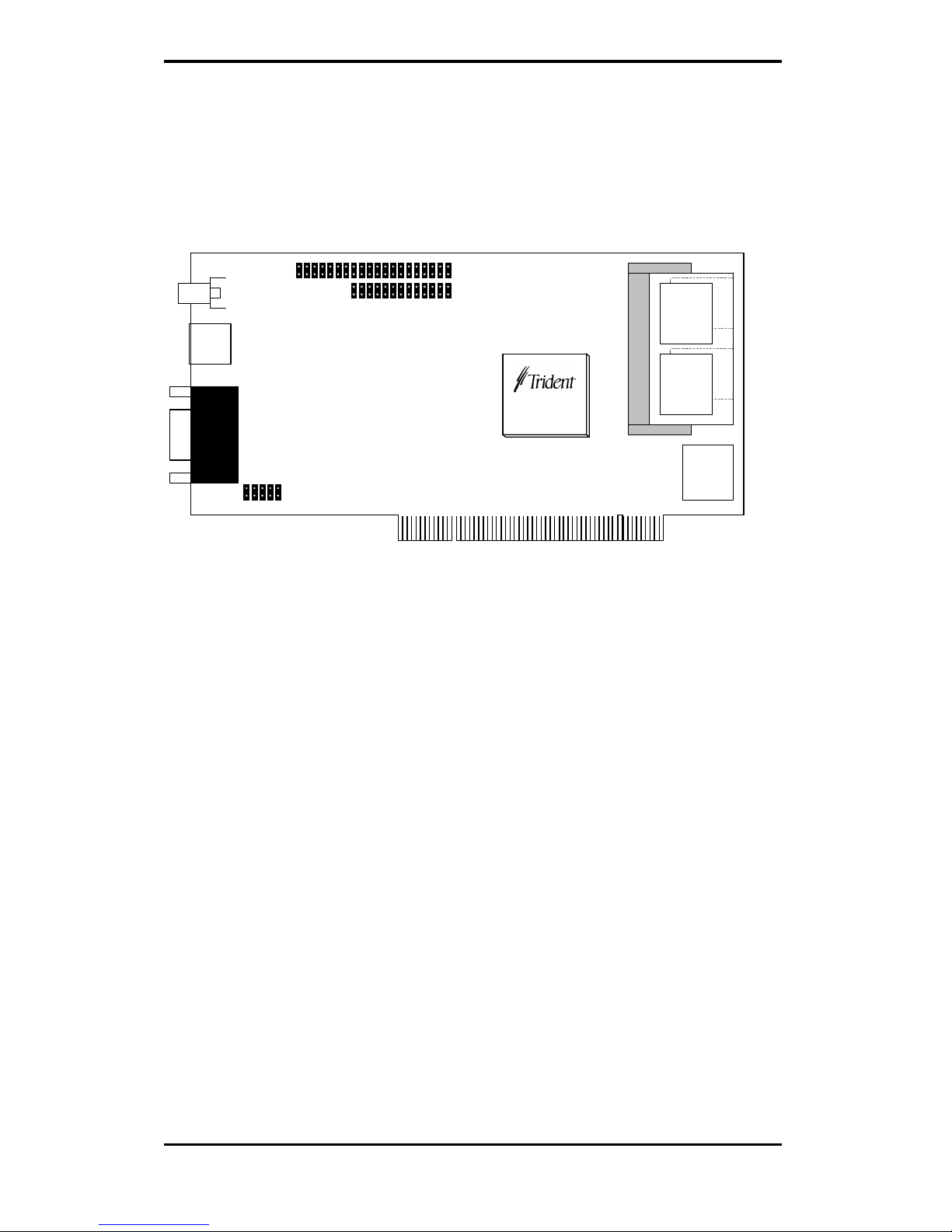
2. Adapter Installation
2.1 Adapter Layout
Composite
TV Out
S-video
TV Out
VGA
Out
CON4
CON5
VGA
BIOS
U9
U4
U3
Feature
Connector
VMI
Connector
256Kx32
SGRAM
256Kx32
SGRAM
3DImàge9850
256x32
SGRAM
256x32
SGRAM
Figure 2-1. 3DImàge985 AGP card with Output to TV
Page 13

8
2.2 Installation Procedures
To install the adapter into your system, follow these steps:
1. Turn OFF all power to your system, including any peripherals
(printer, external drives, modem, etc.).
2. Disconnect the power cord and the monitor cable from the back of
the computer.
3. Unfasten the cover mounting screws on your system and remove
the system cover. Refer to your system user manual for
instructions and to determine the location of the mounting screws.
4. Remove any graphics adapter that already exists on your
motherboard. Start by removing the screw that holds the adapter
retaining bracket in place (keep this screw, you will need it later).
Then, gently pull straight up on the adapter card itself, and
remove it from the motherboard.
5. If appropriate, you can use the expansion slot left vacant by the
existing graphics adapter you just removed. Otherwise, select an
appropriate AGP bus expansion slot for the new adapter. Refer to
your computer system manual for the location of the AGP bus
expansion slots. Remove the retaining screw that holds the slot
cover in place. Slide the slot cover out and put the screw aside
(you will need it to secure the adapter).
If you just removed an existing graphics adapter and are not going
to use that expansion slot, you can install the slot cover you just
removed from the unused expansion slot to cover the open hole.
6. Install the adapter. To install the adapter in the selected
expansion slot, carefully line up the gold-fingered edge connector
on the adapter directly above the expansion slot connector on the
motherboard. Then press the adapter into place, completely,
using only as much pressure as is safely necessary. DO NOT USE
excessive force. Use the (remaining) screw you removed to secure
the adapter retaining bracket in place.
7. Replace the computer cover. Secure the cover with the mounting
screws you removed in Step 3.
You have now completed the installation of your new graphics adapter on
your system. Before you use the system, however, please refer to the
following sections, “Connecting the Display”.
Page 14
9
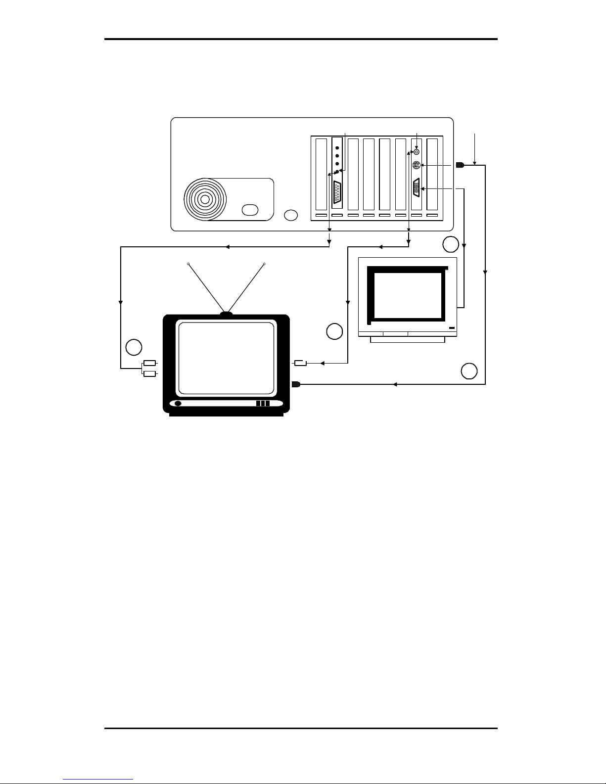
2.3 Connecting the Display and Optional TV
Fan Power Keyboard
Speaker Output Jack
(Sound Card)
Composite
TV Connector
S-Video
TV Connector
VGA
Connector
S-Video Input
(optional)
Composite
Video Input
(optional)
Audio
Input
(optional)
Color
Monitor
Television Set
3
3
1
2
Back of Computer
1. The adapter offers a standard VGA 15-pin analog connector. When
you connect your monitor to the adapter, be sure you have the right
cable and cable connector. Fixed-frequency analog monitors come
equipped with a 15-pin connector. Variable frequency analog or
analog/digital monitors may require a 9-to-15 pin cable connector.
2. If your system is equipped with a sound board, you can also connect a
Y-cable for speaker (single male mini stereo phono jack to double
male RCA jack) from the Speaker-Out jack of the sound board to the
Audio-In jack on your television set.
3. For optional TV connection, please check the back of your TV or VCR
for the presence of a S-Video connector. If such a connector is present,
you will need a S-Video cable to connect S-Video TV-Out on the
adapter to S-Video In on the TV or VCR. If such a connector is not
available, a RCA video cable is needed to connect Composite TV-Out
on the adapter to Composite Video In on the TV or VCR. S-Video
connection is recommended since it provides a higher quality display.
Page 15
10
3. Utilities and Drivers Installation
3.1 Microsoft Windows
3.1.1 MICROSOFT WINDOWS 95 DRIVER INSTALLATION FROM CD
1. ENSURE that MS Windows 95 is up and running properly
using the Trident SVGA driver that it has detected.
2. Insert the Trident Display Driver CD into your CD-ROM
drive.
3. SELECT your CD-ROM drive or TYPE in X:\SETUP (X is
the letter of your CD-ROM drive) under Start… Run of the
task bar for the Trident Display Driver CD Setup menu.
4. SELECT the "Installation" selection bar to install Windows
95 Display Driver.
5. Follow the on-screen instructions to finish Trident display
driver installation.
6. Restart Windows 95 to complete installation.
3.1.2 MICROSOFT WINDOWS 95 DRIVER INSTALLATION FROM DISKETTE
1. ENSURE that MS Windows 95 is up and running properly
using the Trident SVGA driver that it has detected.
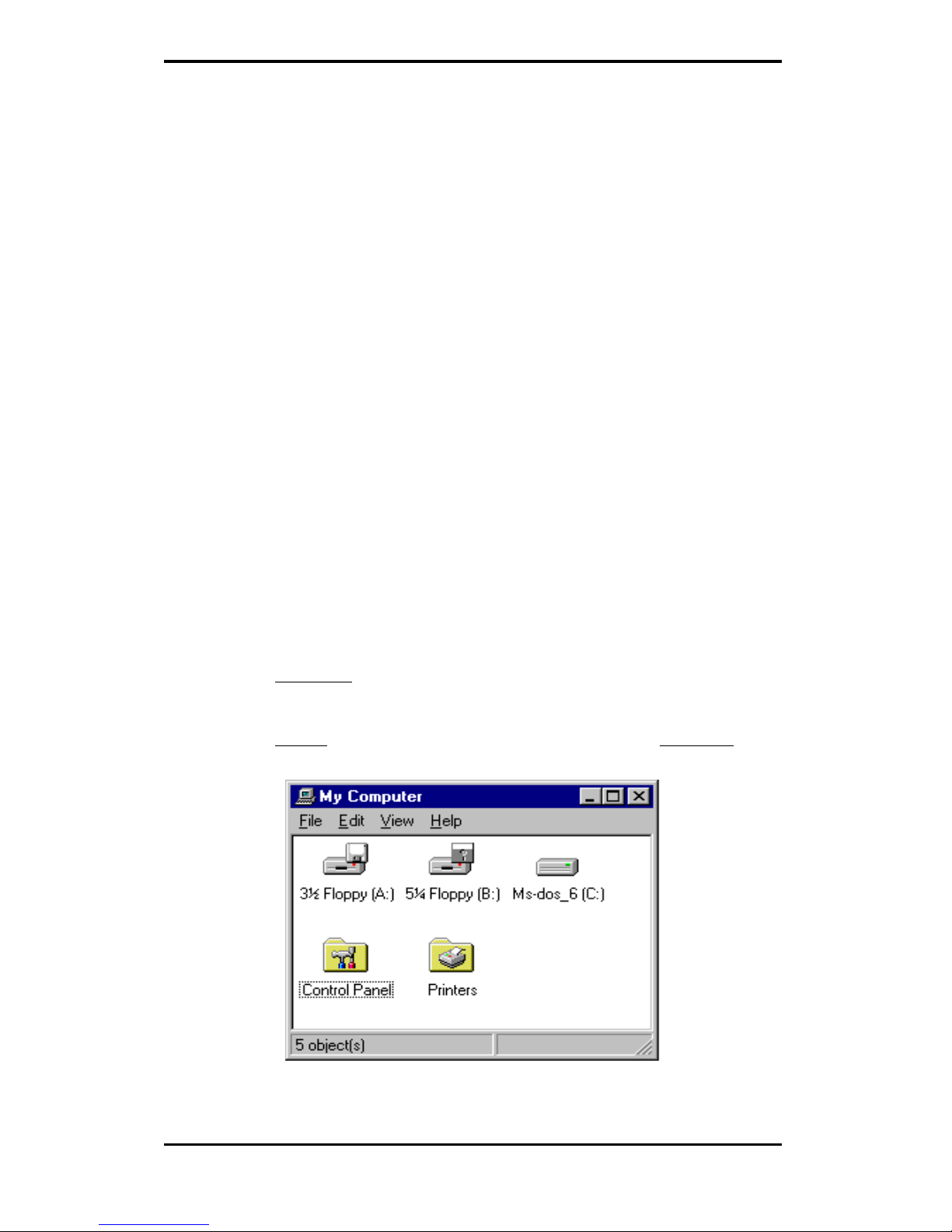
2. OPEN the “My Computer” program group and SELECT the
“Control Panel” icon as shown in Figure 3-1.
Figure 3-1.
Page 16
11
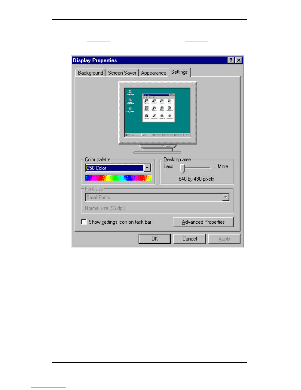
3. SELECT the “Display” icon and then SELECT the “Settings”
page (refer to Figure 3-2).
Figure 3-2.
Page 17
12
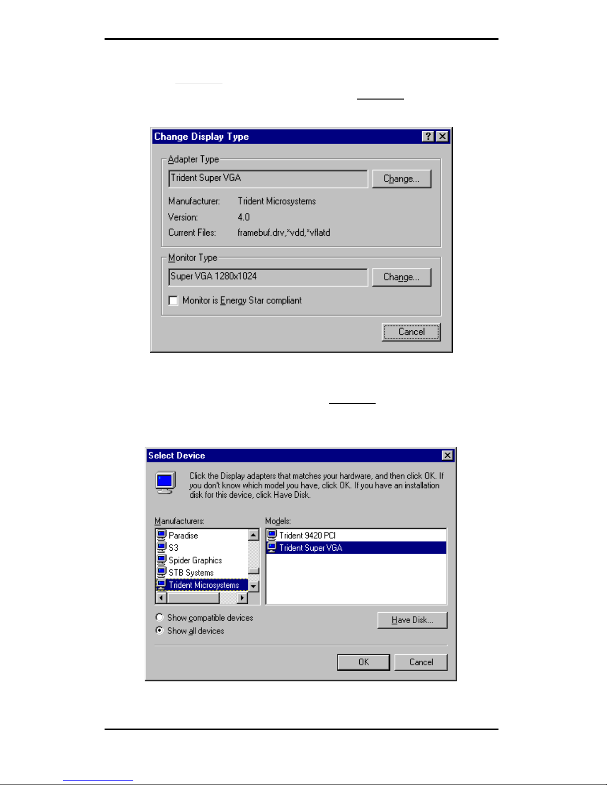
4. SELECT either the “Change Display Type” or the “Advanced
Properties” selection bar, and then SELECT the “Change”
button next to Adapter Type (refer to Figure 3-3).
Figure 3-3.
5. On the “Select Device” page, SELECT the “Have Disk”
button to install the Trident display driver from Disk 2 of the
Drivers and Utilities diskette (refer to Figure 3-4).
Figure 3-4.
Page 18
13
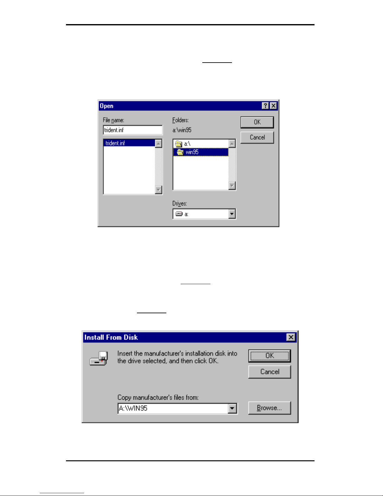
6. After the “Have Disk” button is selected, an “Install From
Disk” window will appear. SELECT the “Browse” button to
browse the directory “X:\WIN95” of your diskette drive where
X: stands for the drive letter of your diskette drive in your
system (refer to Figure 3-5).
Figure 3-5.
7. Once in this directory, the file TRIDENT.INF will appear
under file name list. SELECT “OK” to return to the “Install
From Disk” window (see Figure 3-6). Under the statement
“Copy manufacturer’s files from”, the line X:\WIN95 should
appear. SELECT “OK” to start installing the driver files from
the diskette drive.
Figure 3-6.
Page 19

14
8. After the files have been copied from the diskette drive to the
hard drive, a “Select device” window will appear as shown in
Figure 3-7. Under Models, the line “Trident Imàge 985
(AGP v21xx)” will now be listed.
Figure 3-7.
Page 20
15
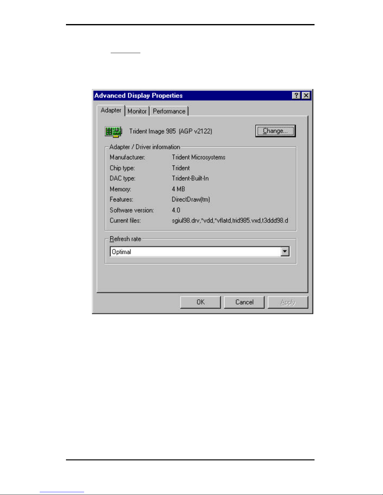
9. SELECT the “OK” button to close the “Select Device”
window and to select the “Color Palette”, “Desktop Area”,
and “Refresh Rate” of your choice under the Trident
accelerated driver (refer to Figure 3-8).
Figure 3-8.
Once the desired color palette (the number of colors), desktop area
(resolution) and refresh rate have been chosen, the Windows 95
system will be re-started using the Trident accelerated driver.
Page 21

16
3.1.3 MICROSOFT WINDOWS NT 4.0 DRIVER INSTALLATION
1. SELECT the “Display” icon in control panel and then
SELECT the “Settings” page.
2. SELECT “Display Type...” button in the “Settings” page.
3. SELECT “Change...” button from the Adapter type section.
4. SELECT “Have Disk...” button from the Change Display
page.
5. Microsoft Windows NT 4.0 will prompt you for the correct
path where the Trident drivers are located. ENTER the path
“X:\NT40” where X: is the drive where Disk 3 of the
3DImàge985 Drivers & Utilities diskette has been inserted.
6. If the driver “Trident Video Accelerator” is listed under the
Display list, SELECT the “OK” button to continue.
7. Once the driver files are copied, RESTART Microsoft
Windows NT 4.0 for the changes to take effect.
8. SELECT the desired color palette (the number of colors),
desktop area (resolution), and refresh frequency in the
settings page of Display Properties and then SELECT the
“Test” button in the same page to determine whether your
selection works properly. SELECT “Apply” to active the
selected mode.
Page 22
17
3.1.4 MICROSOFT WINDOWS 3.1X DRIVER INSTALLATION
The graphic installation program (TINSTALL) supports a simple six-step
installation procedure for the display driver setup program, the power
management program and the UNinstall program.
To use TINSTALL, follow the 6 steps below:
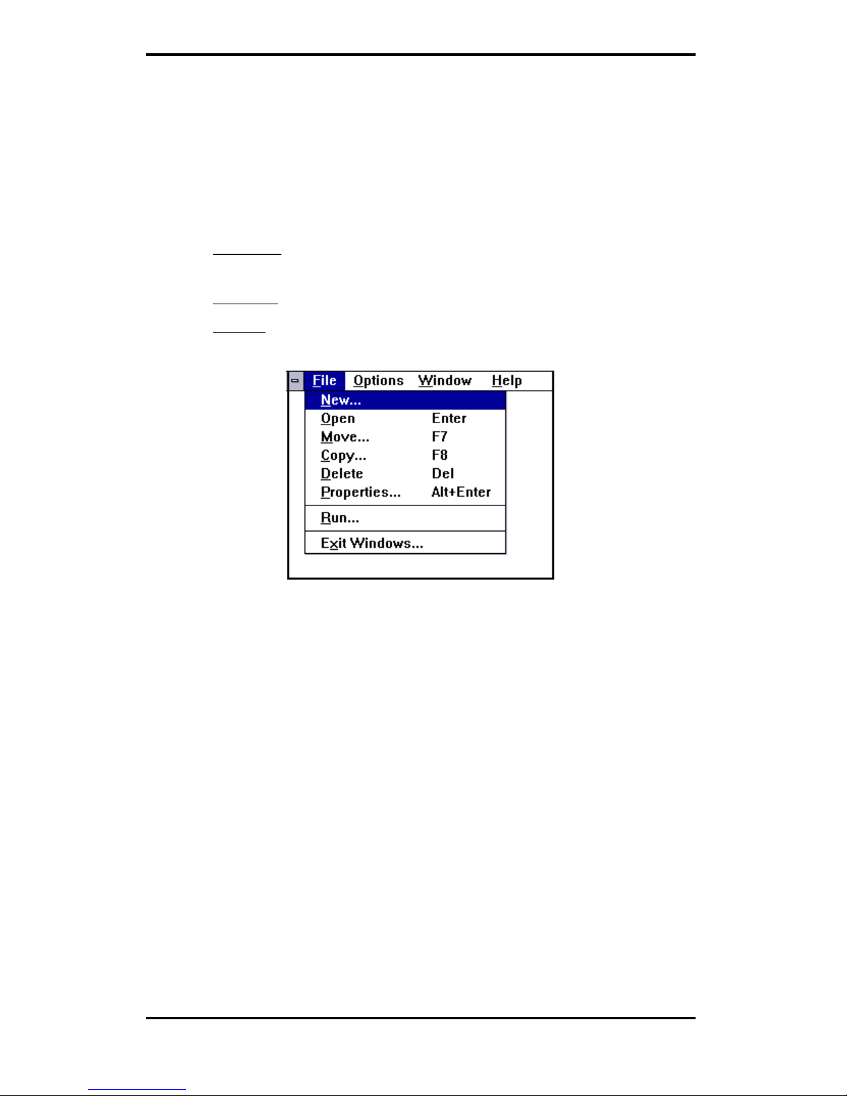
þ 1. ENSURE that MS Windows 3.1x is up and running properly,
using the standard VGA driver.
þ 2. SELECT the MAIN group in Program Manager.
þ 3. CLICK on FILE or press ALT + F (see Figure 3-9)
Figure 3-9.
Page 23

18
þ 4. CLICK on RUN or PRESS R to select command line.
þ 5. TYPE in “A:TINSTALL” (if the display driver disk is in the B
drive then TYPE in “B:TINSTALL”) and then PRESS ENTER
(see Figure 3-10).
Figure 3-10.
þ 6. A menu will appear, presenting a choice of Express or Custom
Installation.
Express installation is quick and decision free. Display drivers will be
copied into the TRIDENT.SGI directory and Utility files will be copied
into the TRIDENT.UTL directory. Once all files are copied, a program
group called DISPLAY DRIVER AND UTILITIES will be created.
Custom installation allows control over file storage and in what program
group the icons are placed. The first dialog box that appears shows the
default directory to which the display drivers will be copied. To change the
directory name select the default name, delete it and then enter the desired
directory name. Once the desired directory name is selected, continue the
installation procedure by selecting CONTINUE, or by pressing ENTER.
The next dialog box displays a summary of where files are stored. Select
CONTINUE to copy the drivers and utilities files. When all files are copied,
the program will present a choice of program groups where the icons will
be created. Create a new group to place the utility icons or select from preexisting groups (e.g. main, applications, accessories etc.).
Page 24

19
When all necessary files are copied and a group name is selected, the
TINSTALL program will create three icons:
þ a. Screen Control (Used to configure display drivers).
þ b. DPMS (Used for power management configurations).
þ c. UNinstall (Used to delete the installed TRIDENT drivers).
NOTE: Different “display driver set” versions
cannot be installed to the same
directory name.
“Display driver sets” of the same version number (e.g. US6.x ) will replace
the existing one.
3.1.4.1 SCREEN CONTROL
The Screen Control panel contains controls for setting screen resolution,
color depth, font size, refresh rates. Not all combinations of screen
resolution, color depth, font size and refresh rate are attainable.
Color depths of 16, 256, 64K, or 16.7M colors can be selected by clicking
next to the desired option. Color depth determines the number of colors
that may be simultaneously displayed on the screen. The selected color
depth determines the possible resolutions.
Screen resolutions of 640x480, 800x600, 1024x768, 1280x1024 or
1600x1200 can be selected by clicking next to the available options. The
virtual screen size is automatically adjusted to be at least as large as the
selected screen resolution.
Available refresh rates are dependent on the selected color depth and
resolution. The “Back to Default” option is used to reset the refresh rate to
the factory default value in case your monitor does not support a high
refresh rate.
Page 25

20
3.1.4.1.1 Configuring the Display Driver
þ Select the color depth first.
þ Select the resolution.
þ Select the font size (if available as an option).
þ Select the refresh rate.
þ Click on OK. If the current driver does not support the selected
configuration, Windows will have to be restarted.
Figure 3-11.
Page 26

21
3.1.4.1.2 DDC Monitor Auto Detection
If your monitor is a “PLUG & PLAY” monitor and is in compliance with
VESA DDC2 Standard, the display driver will automatically detect the
information provided by the DDC2 complaint monitor. If the display
driver is not able to correctly detect the information provided by the
monitor, a message will be displayed that allows you to:
Accept it: The display driver will save the information from the DDC2
monitor that it was able to detect.
Ignore DDC: The display driver will not save the information from the
DDC2 monitor and this monitor will not be treated as a DDC2 complaint
monitor.
Try Again: The display driver will attempt again to detect the information
provided by the DDC2 monitor.
Figure 3-12.
Page 27

22
If the display driver is able to detect the monitor successfully, the correct
information will be shown once the button “DDC Monitor” in the
Advanced page of the Screen Control panel is selected.
Figure 3-13.
Page 28
23
3.2 Live Video Capture Driver
Video Capture is the process of accepting video data from an outside
source, such as TV tuner, VCR, Laser Disc Player or a Camcorder and
writing it to the frame buffer. The data stored in the frame buffer can then
be displayed on the monitor or stored in the hard disk drive. The
3DImàge985 is capable of video capture through the Feature Connector
and the Video Module Interface (VMI) Host Connector.
The ability to capture video data is supported by the 3DImàge985 chip set;
however, additional adapter or hardware may be required to activate this
feature. Please check with your dealer to find out if this optional feature is
available on your video adapter card.
Before installation of 3DImàge985 AVI drivers, both 3DImàge985display
driver and Microsoft Video for Windows 1.1e Runtime have to be installed.
Installation procedures for 3DImàge985 display driver is in section 3.1.4 of
this guide and installation procedures as well as installation software for
Microsoft Video for Windows 1.1e can be found in the Microsoft Video for
Windows 1.1e software package which may be purchased separately.
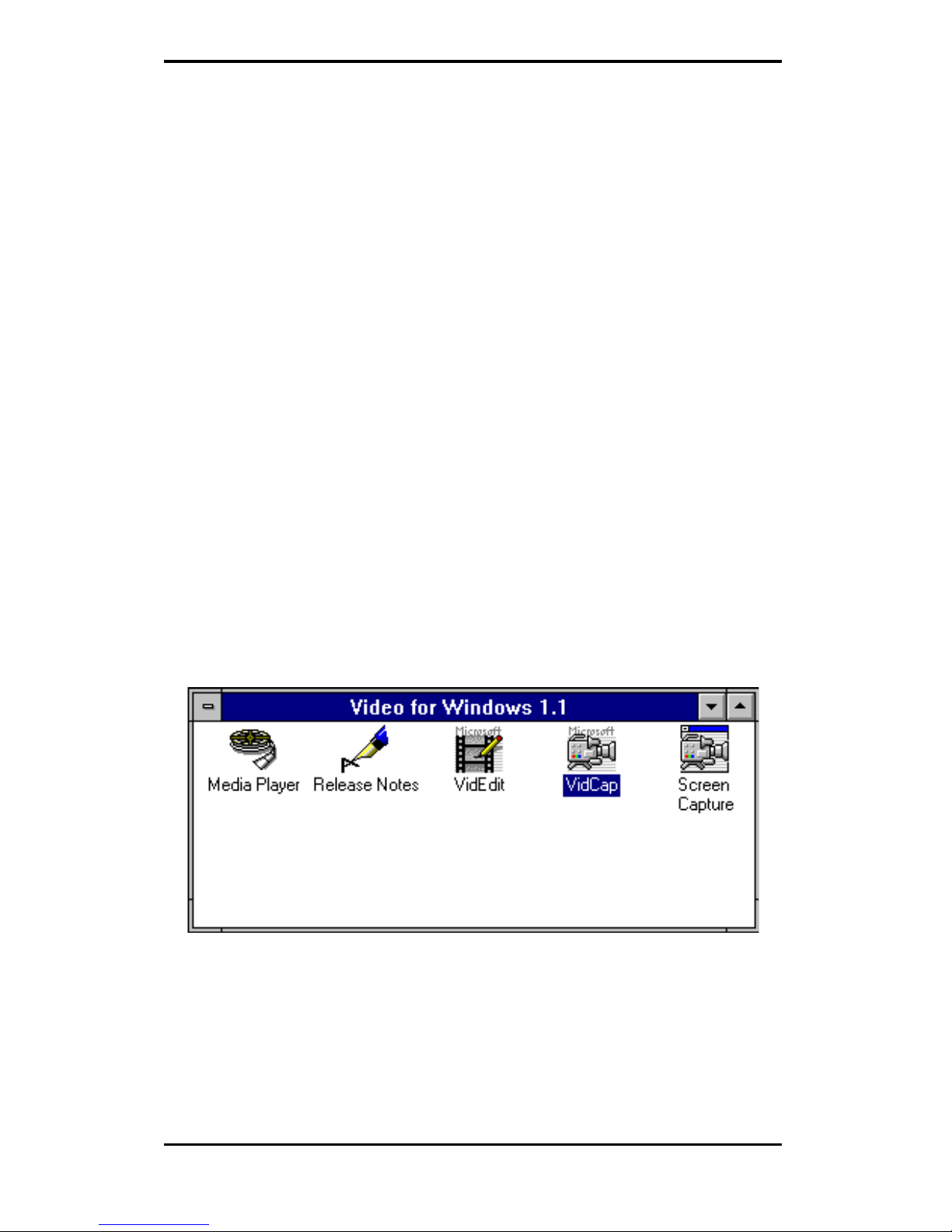
While installing Microsoft Video for Windows 1.1e, both Video Playback
and Video Tools programs have to be installed to be able to use the Video
Capture tools. Once Video for Windows 1.1e has been installed
successfully, the Video for Windows program group will display the
programs as shown in Figure 3-14.
Figure 3-14.
Page 29

24
The 3DImàge985 AVI drivers can be installed by following these steps
below:
1. SELECT the MAIN group in Program Manager.
2. CLICK on FILE or PRESS ALT + F
3. CLICK on RUN or PRESS R to select command line.
4. TYPE in “A:\AVISETUP.EXE” (change the drive letter if the
3DImàge985 AVI driver diskette is in drive B:) and then
PRESS ENTER.
Page 30

25
5. The Trident AVI Drivers Setup screen will appear. PRESS
“Continue” to start installation (See Figure 3-15).
Figure 3-15.
Page 31

26
6. The next screen will place Trident AVI Drivers in the
directory “C:\WINDOWS\AVIDRV”. Change the path only
if another directory is desired (see Figure 3-16). Click on
“Continue” to complete the installation process of Trident
AVI Drivers.
Figure 3-16.
Page 32
27
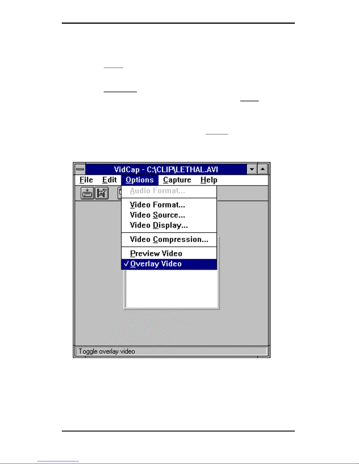
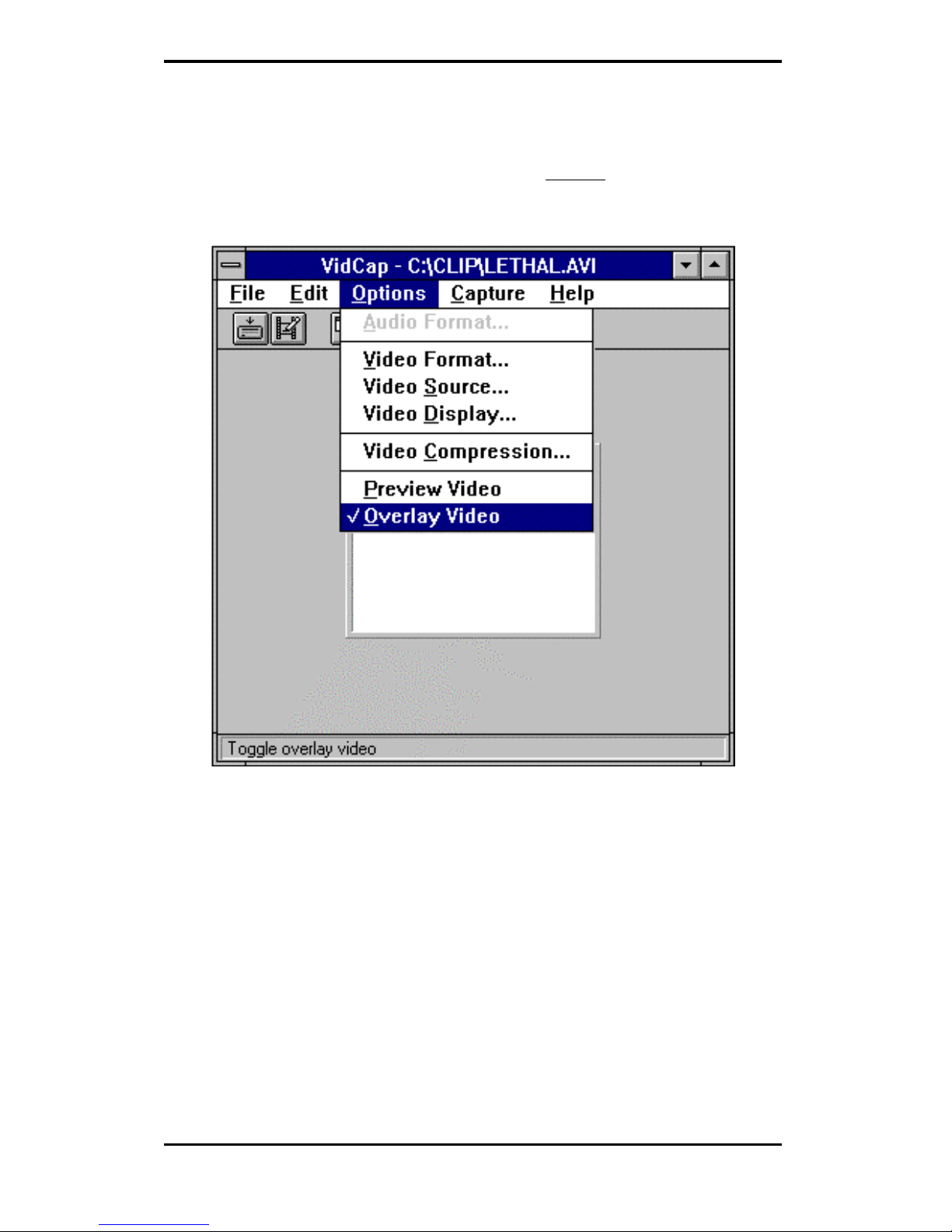
3.2.1.1 Video capture driver usage
1. OPEN the “VidCap” program in the Video for Windows 1.1e
program group.
2. TURN ON the video device that’s currently connected to the
video-in port of the video capture board and PUSH the “Play”
button on the video device to start sending video signals to
the video capture board.
3. In the VidCap program window, CLICK on “Overlay Video”
under Options (See Figure 3-17).
Figure 3-17.
Page 33

28
4. CLICK on Video Source to set the source of the video signal
(see Figure 3-18).
Figure 3-18.
5. SET video source to ”Video” to begin displaying video in the
overlay window.
Page 34
29
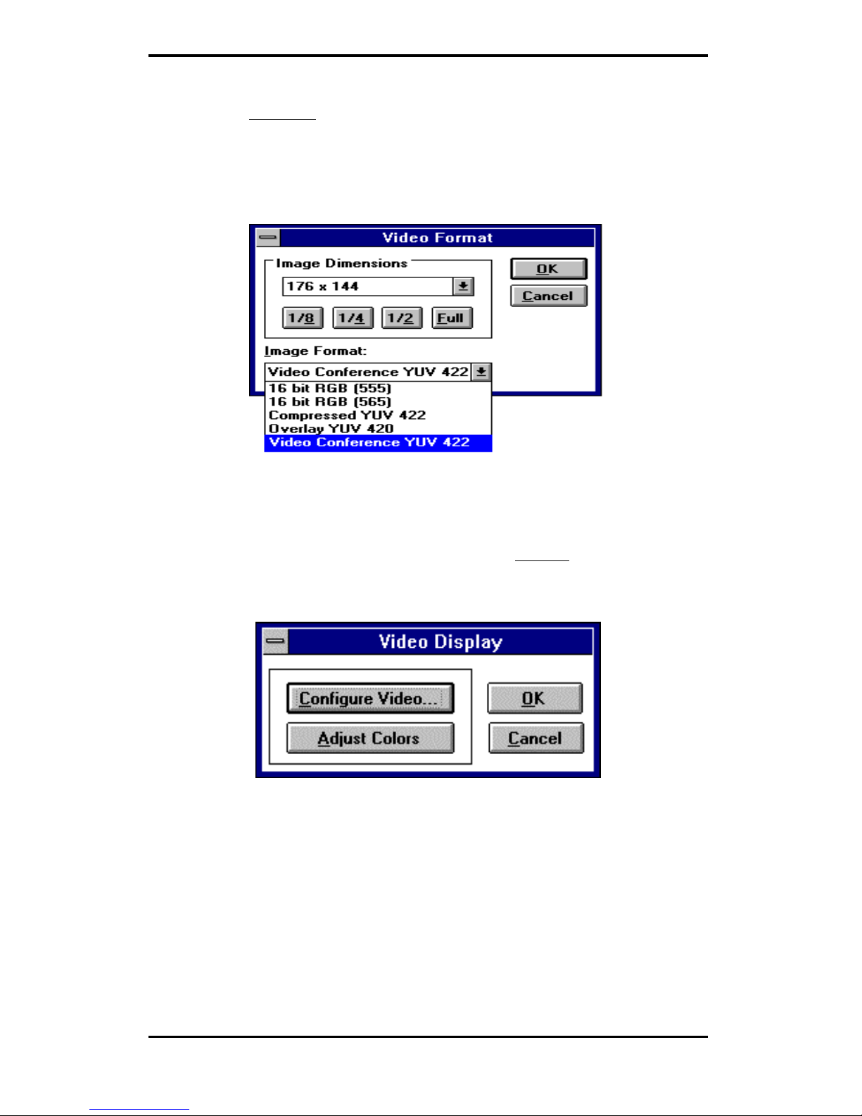
3.2.1.2 Video Overlay adjustments
1. In the VidCap program window, CLICK on “ Video Format”
under Options to set screen size (see Figure 3-19).
Figure 3-19.
Page 35
30
2. SELECT different Image Formats by clicking on one of
choices under Image format selections (see Figure 3-20).
While all five formats allow image dimensions of up to full
screen size, only “Video Conference YUV 422” image format
allows full screen size of 704x576.
Figure 3-20.
3. To configure video or adjust colors, CLICK on “ Video
Display” under Options (see Figure 3-21).
Figure 3-21.
Page 36

31
4. CLICK on the “Adjust Colors” button to make adjustments of
brightness, contrast, saturation and hue. CLICK on
“Configure Video” button to make adjustments on Overlay
Key Control, Display X/Y Offset, and Capture X/Y Offset
(see Figure 3-22).
Figure 3-22.
Page 37
32
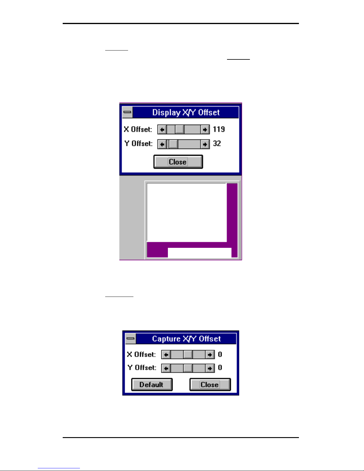
5. CLICK on “Overlay Key Control” to set VGA Color Key to a
color key value other than the default. CLICK on “Display
X/Y Offset” to adjust the video window within the overlay
window. When the video window is centered, it will
completely cover the overlay window (see Figure 3-23).
Video Window
Overlay Window
Figure 3-23.
6. SELECT ‘Capture X/Y Offset” to adjust the color within the
video window if the color does not appear correct (see Figure
3-24).
Figure 3-24.
Page 38

33
3.3 OS/2 Driver Installation
Before installing Trident display driver for the first time, the current
display type has to be VGA mode. The instructions to return to VGA
mode are in the “Recovering from an incorrect display type selection”
section of your OS/2 user’s manual.
Trident’s OS/2 display driver is installed by following these simple steps.
þ 1. PLACE the Trident OS/2 driver diskette into diskette
drive A: or diskette drive B:.
þ 2. OPEN an OS/2 full-screen or OS/2 Window session under
“Command Prompt” of the System folder.
þ 3. PRESS ‘ALT+F1’ after OS/2 shows up in the upper left hand
corner, and then SELECT ‘V’.
þ 3. SWITCH the current drive to the diskette drive where the
Trident OS/2 driver diskette was inserted.
þ 4. At the drive prompt, TYPE the following command:
“INSTALL”.
The Trident LOGO will now appear and a screen that reads “Trident
Display Drivers Setting” will appear after that.
3.3.1 DISPLAYING OR CHANGING SCREEN RESOLUTION
This Trident OS/2 Display Drivers utility supports the following
resolutions with OS/2. The required memory is shown in parentheses.
640x480x256 800x600x65K
800x600x256 1024x768x65K (2M)
1024x768x256 640x480x16.7M
1280x1024x256 (2M) 800x600x16.7M (2M)
640x480x65K
Page 39

34
The first page of the Trident Display Drivers Settings window is labeled
Screen Resolution selection page.
þ SELECT the resolution and color depth
þ ENABLE/DISABLE virtual screen
The second page is the Monitor Model selection page.
þ CLICK on Monitor tab to go to this page.
þ POINT to and CLICK on the down arrow button to show a list of
monitor models.
þ SELECT the monitor model. If you can not find your monitor's model,
SELECT "Default".
The third page is the Refresh Rate selection page.
þ CLICK on Refresh tab to go to this page.
þ The refresh rates displayed are those supported at each resolution by
the monitor specified in the Monitor Model selection page.
þ You can change the refresh rates by CLICKING on down arrow button
and then CLICKING on the desired refresh rate.
þ After the selections, CLICK on the Install button to complete the
installation.
þ REBOOT OS/2 to have this installation take effect.
Page 40

35
3.3.2 SCREEN RESOLUTION CONFIGURATION PROCEDURE
þ 1. DOUBLE-CLICK on the Video configuration folder, and then
DOUBLE-CLICK on the “Display Setting“ object.
þ 2. To change resolution and/or color depth
a) CLICK on “Screen“ tab.
b) SELECT the resolution and color depth.
c) CLICK on “Set“ button.
þ 3. To enable virtual screen
a) POINT to and CLICK “Virtual Screen” on the button
þ 4. To change refresh rate
a) CLICK on Refresh tab.
b) POINT to and CLICK on the down arrow button.
c) SELECT the refresh rate.
d) CLICK on the “Set“ button to take effect.
e) If you don't want the selected refresh rate, CLICK the
Undo button or PRESS the 'U' key to return to previous
refresh rate.
Page 41

36
3.3.2.1 Virtual Screen
Virtual screen allows the monitor to display the information of a larger
screen within the physical borders of the monitor. On some monitors the
display fonts at higher resolutions, such as 1024x768, may be too small to
read. If virtual screen is enabled for 1024x768 resolution, the display font
will be larger in 640x480 resolution or 800x600 resolution; however, the
information displayed will be that of 1024x768 resolution.
To enable virtual screen:
þ 1. SET UP the Trident display at a higher resolution, such as
1024x768.
þ 2. SHUTDOWN the system and then re-start the system.
þ 3. GO into the Video configuration folder and CLICK on the
“Display Setting“ object to select the screen resolution page.
þ 4. CHOOSE a smaller resolution such as 640x480 and CHECK
the line that says "Virtual Screen On".
þ 5. CLICK on the ‘Set‘ button and the screen will automatically
be set to physical screen size of 640x480 with virtual screen
size of 1024x768.
To return to base mode from virtual screen:
þ 1. SELECT base mode screen resolution.
þ 2. SELECT ‘Set’.
Notes:
1. To activate virtual screen, color depth has to be the same for both the
physical screen and virtual screen.
2. Virtual screen size has to be larger than physical screen size.
3. If you change the resolution, you must reboot OS/2 to have the
changes take effect.
4. If you decide to change your hardware system configuration, such as
upgrading video memory or system memory, you should
a) Change the resolution to VGA.
b) Change the hardware configuration.
c) Re-install the Trident OS/2 Display Drivers.
Page 42

37
3.4 DOS Utilities
The Utility Installation program is used to install and retrieve instructions
on:
a) Utility programs
b) Non-Windows applications display drivers.
Run the Utility Installation Program by executing the following steps:
þ 1. INSERT the Drivers and Utilities Disk #2 in the floppy drive.
þ 2. TYPE in “README” at the DOS prompt.
þ 3. A numbered list of available destination drives will be
displayed on the screen. SELECT the destination drive by
TYPING in the corresponding number; e.g., to select drive C,
type in “1” (see Figure 3-25).
Figure 3-25.
Page 43

38
4. Files and subdirectories will be expanded into the newly
created directory TVGAUTIL. A new menu will then be
displayed on the screen, showing a list of on-line instructions
(see Figure 3-26).
Figure 3-26.
þ 5. Selecting A will display the contents of all drivers in the list.
þ 6. Selecting B will display instructions on the available utility
programs.
þ 7. Selecting C will display instructions on how to install display
drivers for non-Windows applications.
3.4.1.1 SVM.EXE
SVM is a menu-driven program designed to select and test all video modes
available to the adapter.
HOW TO USE SVM
The SVM program can be executed in either of two ways: by calling up the
menu and selecting from the menu choices, or by entering the desired
mode directly with a specific command line.
Page 44
39
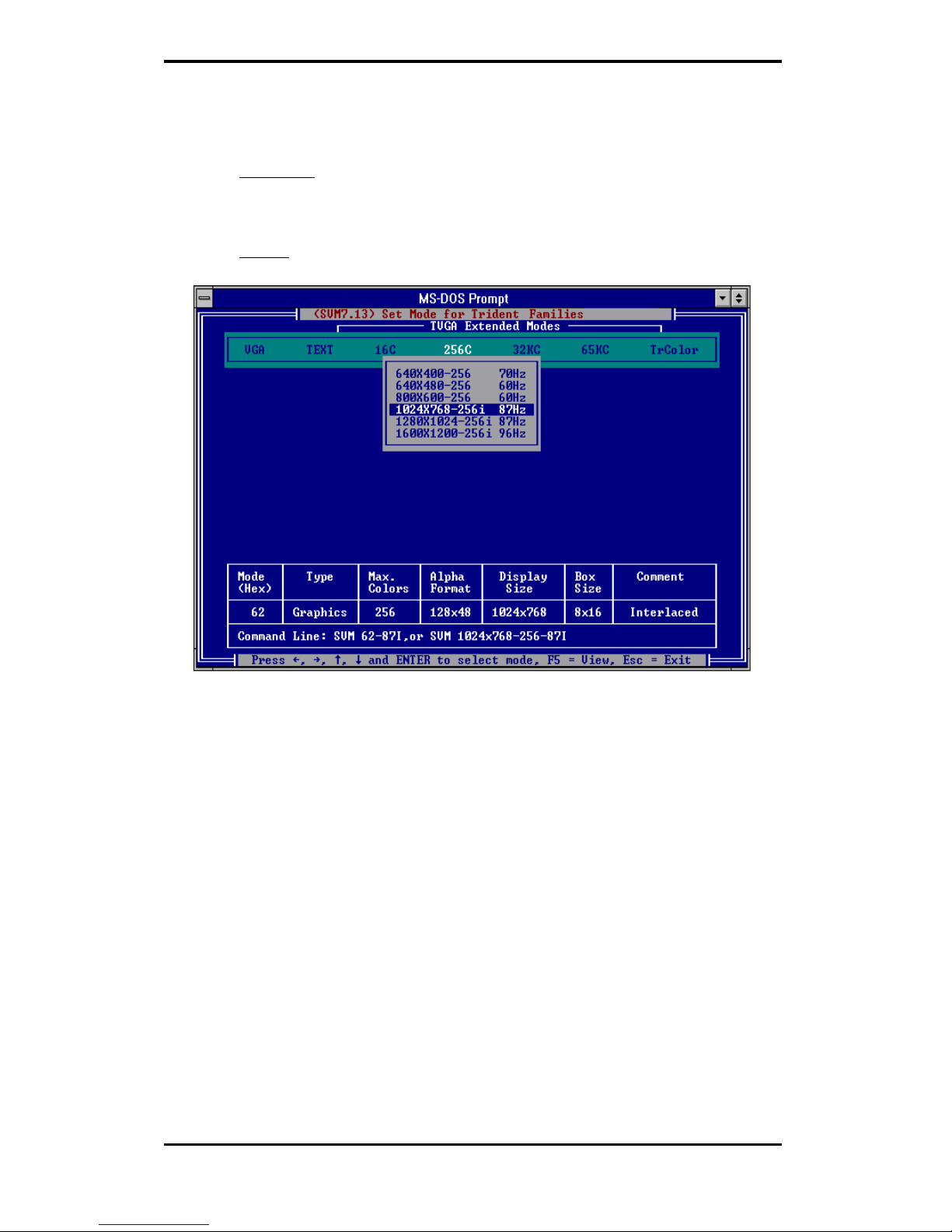
HOW TO USE SVM FROM THE MENU
þ 1. SWITCH directory to “X:\TVGAUTIL\UTILITY” where X: is
the drive where the Trident Utility and DOS
Application driver files have been copied.
þ 2. TYPE SVM to call up the menu (see Figure 3-27).
Figure 3-27.
The top bar shows the available color depths. This is traversed
through by use of the right/left arrow keys.
The program provides all the different resolutions supported by
the chip under each color depth. These resolutions are traversed
by the up or down arrow keys. The graphics adapter can be tested
for each resolution/ mode by first high-lighting the selection (e.g.
1024x768-256 colors as shown in Figure 3-27) by use of the
arrow keys, then pressing the F5 key.
The graphics adapter can be run at a selected mode by first selecting the
mode and then pressing ENTER.
Page 45

40
HOW TO USE SVM FROM THE COMMAND LINE
The SVM program may be used to select a mode directly from the
command line following two simple steps:
þ 1. SWITCH directory to “X:\TVGAUTIL\UTILITY” where X: is
the drive where the Trident Utility and DOS
Application driver files have been copied.
þ 2. TYPE in SVM [mode number] and PRESS ENTER.
For example, to run the graphics adapter in mode 62H, the command line
would be:
SVM 62 <ENTER>
Page 46

41
3.5 Optional TV Out
In Windows 95, use 'Television' control page and 'Display Device' control
page to select television only features in display properties once the display
driver for Windows 95 has been installed. The 'Television' control page
allows the user to select 'Underscan' or 'Overscan', to select 'Interlaced' or
'Non-interlaced', to adjust the 'Screen Shift' of the television display
horizontally and to select the degree of flicker reduction under Advance
control button. The 'Display Device' control page allows the user to switch
from color monitor to TV as the default display device and vice versa.
In Windows 3.x, use the Display Control program in Display Driver and
Utility Program Group to access TV display features and to switch from
color monitor to TV as the default display device and vice versa. The
Display Control program allows the user to select Underscan or Overscan,
to select interlaced or non-interlaced, to select degree of flicker reduction
and to adjust screen shift both horizontally and vertically.
In DOS, a TSR program "TVDISP" is available in the directory of
"X:\TVGAUTIL\UTILITY" (where X is the letter of your hard disk drive).
This program allows the user to select 'Underscan' or 'Overscan', to select
'Interlaced' or 'Non-interlaced', to switch from color monitor to TV as the
default display device and vice versa, to adjust the 'Screen Shift' of the
television display both horizontally and vertically, and to contract or
expand the size of screen both horizontally and vertically. More
information about the TVDISP program is available in the REAME.TXT
file of this directory.
Page 47

42
Conventional broadcast TV or VCR content provides an "Overscaned"
viewing area in order to ensure that the entire visible screen is used. The
result is that portions of the image along the border are beyond the
physical screen. The actual visual area lost is dependent on the individual
TV model. On the other hand, a PC system display content should be
within the boundaries of the physically viewable screen. This is called
underscan. When the TV is used as the display device in a PC, display
hardware needs to control the image generation circuitry to drive the
underscan timing to the TV.
Besides generating interlaced timing, hardware may have the option to
drive non-interlaced timing to the TV. A non-interlaced display will
remove much of the flicker effect but reduce the detail of the image.
The interlaced timing of a TV causes a flickering effect on the screen.
Depending on the TV standard and tube phosphor material, the severity of
flicker differs from one brand and model of TV to another. Since TV
content is almost always full-motion video or animation, flicker is not as
noticeable as it is when the screen content is stationary. Flickers are caused
by a television’s low frame rate as well as the interlacing of adjacent scans.
This flicker is most obvious when a particular scan contrasts highly with
the scans directly above and below, such as a black horizontal line on a
white background. This type of flicker can be greatly reduced by
3DImàge985's built-in flicker reduction filter.
Page 48

43
4. Frequently Asked Questions (FAQ)
Q1 What is AGP and what does it mean?
Answer
The Accelerated Graphics Port (AGP or A.G.P) is a high
performance, component level interconnect targeted at 3D graphical
display applications and is based on a set of performance
extensions or enhancements to Peripheral Component Interconnect
(PCI). A typical 3D application requires tremendous amount of
memory to render 3D scenes. AGP provides a cost-effective way of
shifting some of 3D rendering data structures into system memory
from frame buffer of 3D graphics accelerator. The 3DImàge985
supports the higher performance 2X or execute mode of AGP which
allows data structures to be executed in system memory space
without being copied into the frame buffer of 3D graphics
accelerator prior to use by the accelerator.
Q2 Why do we need 3D graphics capability in our PC?
Answer
3D technology is becoming increasingly important (and common)
not only in games, but also in other applications such as VRML,
which allows 3D scene descriptions in Web applications. 3D
technology is used for image editing, modeling, and an increasing
number of in home and business applications. In games, as well as
other applications, 3D acceleration not only allows better visual
qualities and more realistic scenery attributes than software alone,
but it also allows a higher frame rate, which translates into a more
interactive experience for the end users.
Q3 What does “Rendering Engine” mean?
Answer
“Rendering Engine” generically applies to the part of the graphics
engine that draws 3D primitives, usually triangles. In most
implementations, the rendering engine is responsible for
interpolation of edges and "filling in" the triangle.
Q4 What does the set-up engine do in a graphics controller?
Answer
A set-up engine allows drivers to pass triangles in the form of raw
Page 49

44
vertex information; whereas, most common designs force triangles
to be pre-processed for the rendering engine in terms of delta
values for edges, color, and texture.
Q5 Why does a 3D graphics chip need to have both a rendering
engine and a setup engine?
Answer
Any “3D application”, a game, VRML, or modeling package, can
benefit from 3D rendering. This is especially true of applications that
use texturing extensively; because texturing and texture filtering are
very intensive operations at the pixel level in terms of CPU
operations and demands for memory bandwidth. Without a set-up
engine in a graphics controller, the CPU has to calculate the delta
values for edges, color, and textures; the drivers need to handle ten
(10) times more extensive data. This results in slower 3D pipeline
operations between the CPU and the graphics controller.
Q6 If we use powerful CPUs, such as a Pentium™ 200, can a
standard 2D graphics card achieve 3D performance?
Answer
Yes and no. Software rendering can take advantage of "tricks"
learned by force of necessity through years of trial and error. With
such stratagems, the speed of software rendering for simple scenes
can approach that of low-level hardware 3D rendering. On the other
hand, as scenes become more complex, there are conflicts between
using the CPU for high-level game logic, geometry, lighting, and
rendering, all of which increase their demands. No current CPU or
system can perform advanced quality-enhancements (bilinear
filtering and alpha blending) in real time. Even general case texture
mapping with RGB lighting is too much for the current CPU
generation.
Q7 What does "software 3D" mean ?
Answer
Software 3D is generally used to mean using non-specific (2D)
hardware in conjunction with the CPU to render for 3D applications.
Some of these techniques allow usable 3D applications when highpowered and/or MMX™-equipped CPU's are employed along with
special-case software optimization techniques. As stated above, SW
3D can achieve credible results with today's applications, but the
rising popularity of good 3D hardware at the consumer price level is
Page 50

45
inexorably compelling the public to expect hardware level scene
enhancements and frame rates.
Q8 What is “SGRAM”?
Answer
Synchronous Graphics Random Access memory (SGRAM) is a new
and improved type of memory, custom-designed for graphics use.
Q9 What is the advantage of SGRAM as compared to ordinary
DRAM?
Answer
SGRAM is now capable of running at much higher speeds than fast
page or EDO DRAM. Also, SGRAM is able to execute a small
number of frequently executed operations, such as buffer clears,
specific to graphics applications, independently of the controller.
Q10 What is 3DImàge985?
Answer
The 3DImàge985 is one of the first of the "second generation" 3D
controllers which will catapult 3D applications of all types into the
PC mainstream by providing the feature set and performance
necessary for compelling 3D applications. It does this by combining
proven VGA, video, and graphics acceleration with an advanced 3D
rendering core including a set-up engine and a full 3D feature set.
Q11 Why should the customer choose Trident 3DImàge985 over
other alternatives?
Answer
As stated above, the 3DImàge985 is second generation. This means
that it combines the full feature sets often seen in first generation
designs with the essential elements that were missing in those
designs:
• High performance 3D achieved by innovative design
• Careful attention to system level integration
• Aggressive use of existing and recently developed technology,
such as single-cycle SGRAM memory interfaces
The 3DImàge985 represents an overall competency in all areas,
with excellence in some important ones, such as 3D and video, that
make it the best choice on the market today for both consumer and
commercial applications.
Page 51

46
Page 52

47
5. Troubleshooting
The following are some recommended steps to take if the GUI accelerator
adapter will not boot or operate properly in your system:
1. Ensure that the monitor or TV brightness and contrast controls
are properly adjusted.
2. Check to see if your monitor or TV is properly connected to the
card. Be sure your monitor's pin definitions match those of your
GUI accelerator card (See Appendix B). For TV out, ensure that
the composite signal is connected to a “Video Input” RCA jack on
the TV (or check the S-video connection). Read the TV owner’s
manual to select the proper signal jack for the display.
3. Turn the system on and confirm that the power supply is
operating properly; i.e., that the fan operates and the system
power light turns on.
4. Check to see if the card is firmly seated in its AGP bus expansion
slot. It should not be making contact with any other cards in the
system.
Note: Turn the system off before adjusting the card.
Problem: Windows hangs up during or after installing a driver.
Solution A: Reread installation procedures to be sure you have installed
the drivers correctly.
Problem: Windows color palette does not look right or colors
changing.
Solution: Most likely a defective RAMDAC, memory chip, clock chip,
or crystal. Contact your dealer to have the problem repaired.
Problem: Can't display certain modes.
Solution A: Run the SVM program (See the User's Guide for more
information on the SVM program). If the SVM program
fails, go to Solutions B, and C.
Solution B: Check to see that there is enough memory on the GUI
accelerator to run this mode. For example, to run display
mode 79H (1024x768-64K colors, refer to the tables in
Section 2), 2 MB of display memory is required.
Solution C: If Solutions A, or B do not resolve this problem, it may be
hardware related. Check the specifications of the monitor.
Page 53

48
6. Appendix A: Video Mode Table
The adapter’s video modes include all of the following:
TABLE 6-1: STANDARD VGA MODE SUPPORT
Mode
#
Resolution
-Colors
Horz
KHz
Vert
Hz
Mem
Req
Text
Res
Mode
Type
TV
Out
0h,1h 320x200-16 31.4 70 2M 40x25 Text N,P
2h,3h 640x400-16 31.4 70 2M 80x25 Text N,P
4h,5h 320x200-4 31.4 70 2M 40x25 Graph N,P
6h 640x200-2 31.4 70 2M 80x25 Graph N,P
7h 720x350-Mono 31.5 70 2M 80x25 Text N,P
Dh 320x200-16 31.4 70 2M 40x25 Graph N,P
Eh 640x200-16 31.4 70 2M 80x25 Graph N,P
Fh 640x350-2 31.4 70 2M 80x25 Graph N,P
10h 640x350-16 31.4 70 2M 80x25 Graph N,P
11h 640x480-2 31.4 60 2M 80x30 Graph N,P
12h 640x480-16 31.4 60 2M 80x30 Graph N,P
13h 320x200-256 31.4 70 2M 40x25 Graph N,P
Page 54

49
TABLE 6-2: EXTENDED VGA MODE SUPPORT
Mode
#
Resolution
-Colors
Horz
KHz
Vert
Hz
Mem
Req
Text Res Mode
Type
TV
Out
20/1h_2 864x480-32K/64K 37.3 75 2M 108x30 Graph
20/1h_1 864x480-32K/64K 31.5 60 2M 108x30 Graph
22h_2 864x480-256 37.3 75 2M 108x30 Graph
22h_1 864x480-256 31.5 60 2M 108x30 Graph
23h_2 864x480-16M 37.3 75 2M 108x30 Graph
23h_1 864x480-16M 31.5 60 2M 108x30 Graph
24/5h 1024x600-32K/64K 38.0 60 2M 128x37 Graph
26h 1024x600-256 38.0 60 2M 128x37 Graph
27h 1024x600-16M 38.0 60 4M 128x37 Graph
2Ch 320x200-256 31.6 70 2M 40x12 Graph
2Dh_4 320x240-256 43.3 85 2M 40x15 Graph
2Dh_3 320x240-256 37.5 75 2M 40x15 Graph
2Dh_2 320x240-256 37.8 72 2M 40x15 Graph
2Dh_1 320x240-256 31.4 60 2M 40x15 Graph
2Eh_3 400x300-256 53.7 85 2M 50x18 Graph
2Eh_2 400x300-256 46.8 75 2M 50x18 Graph
2Eh_1 400x300-256 37.8 60 2M 50x18 Graph
32h_5 512x384-256 68.7 85 2M 64x24 Graph
32h_4 512x384-256 60.0 75 2M 64x24 Graph
32h_3 512x384-256 56.4 70 2M 64x24 Graph
32h_2 512x384-256 48.3 60 2M 64x24 Graph
32h_1 512x384-256 35.5 87i 2M 64x24 Graph
3Bh 320x200-16M 31.6 70 2M 40x12 Graph
3Ch_4 320x240-16M 43.2 85 2M 40x15 Graph
3Ch_3 320x240-16M 37.5 75 2M 40x15 Graph
3Ch_2 320x240-16M 37.8 72 2M 40x15 Graph
3Ch_0 320x240-16M 31.4 60 2M 40x15 Graph
3Dh_3 400x300-16M 53.7 85 2M 50x18 Graph
3Dh_2 400x300-16M 46.8 75 2M 50x18 Graph
3Dh_1 400x300-16M 37.8 60 2M 50x18 Graph
3Eh_4 512x384-16M 60.0 75 2M 64x24 Graph
3Eh_3 512x384-16M 56.4 70 2M 64x24 Graph
3Eh_2 512x384-16M 48.3 60 2M 64x24 Graph
3Eh_1 512x384-16M 35.5 87i 2M 64x24 Graph
42/3h 320x200-32K/64K 31.6 70 2M 40x12 Graph
44/5h_4 320x240-32K/64K 43.2 85 2M 40x15 Graph
44/5h_3 320x240-32K/64K 37.5 75 2M 40x15 Graph
44/5h_2 320x240-32K/64K 37.8 72 2M 40x15 Graph
Page 55

50
Mode
#
Resolution
-Colors
Horz
KHz
Vert
Hz
Mem
Req
Text Res Mode
Type
TV
Out
44/5h_1 320x240-32K/64K 31.4 60 2M 40x15 Graph
46/7h_4 400x300-32K/64K 53.7 85 2M 50x18 Graph
46/7h_3 400x300-32K/64K 46.8 75 2M 50x18 Graph
46/7h_2 400x300-32K/64K 37.8 60 2M 50x18 Graph
48/9h_5 512x384-32K/64K 68.7 85 2M 64x24 Graph
48/9h_4 512x384-32K/64K 60.0 75 2M 64x24 Graph
48/9h_3 512x384-32K/64K 56.4 70 2M 64x24 Graph
48/9h_2 512x384-32K/64K 48.3 60 2M 64x24 Graph
48/9h_1 512x384-32K/64K 35.5 87i 2M 64x24 Graph
50h 640x480-16 31.5 60 2M 80x43 Text
51h 640x473-16 31.5 60 2M 80x43 Text
52h 640x480-16 31.5 60 2M 80x60 Text
53h 1056x350-16 31.3 70 2M 132x25 Text
54h 1056x480-16 31.3 60 2M 132x30 Text
55h 1056x473-16 31.3 60 2M 132x43 Text
56h 1056x480-16 31.3 60 2M 132x60 Text
57h 1188x350-16 31.3 70 2M 132x25 Text
58h 1188x480-16 31.3 60 2M 132x30 Text
59h 1188x473-16 31.3 60 2M 132x43 Text
5Ah 1188x480-16 31.3 60 2M 132x60 Text
5Bh_1 800x600-16 37.8 60 2M 100x75 Graph
5Ch 640x400-256 31.6 70 2M 80x25 Graph N,P
5Dh_4 640x480-256 43.2 85 2M 80x30 Graph
5Dh_3 640x480-256 37.5 75 2M 80x30 Graph
5Dh_2 640x480-256 37.8 72 2M 80x30 Graph
5Dh_1 640x480-256 31.4 60 2M 80x30 Graph N,P
5Eh_3 800x600-256 53.7 85 2M 100x37 Graph
5Eh_2 800x600-256 46.8 75 2M 100x37 Graph
5Eh_1 800x600-256 37.8 60 2M 100x37 Graph P
5Fh_5 1024x768-16 68.7 85 2M 128x48 Graph
5Fh_4 1024x768-16 60.4 75 2M 128x48 Graph
5Fh_3 1024x768-16 56.4 70 2M 128x48 Graph
5Fh_2 1024x768-16 48.5 60 2M 128x48 Graph
5Fh_1 1024x768-16 35.5 87i 2M 128x48 Graph
60h 720x480-256 31.4 60 2M 90x30 Graph
61h 720x480-16M 31.4 60 2M 90x30 Graph
62h_5 1024x768-256 68.7 85 2M 128x48 Graph
62h_4 1024x768-256 60.0 75 2M 128x48 Graph
62h_3 1024x768-256 56.4 70 2M 128x48 Graph
Page 56

51
Mode
#
Resolution
-Colors
Horz
KHz
Vert
Hz
Mem
Req
Text Res Mode
Type
TV
Out
62h_2 1024x768-256 48.3 60 2M 128x48 Graph
62h_1 1024x768-256 35.5 87i 2M 128x48 Graph
63h_4 1280x1024-16 91.1 85 2M 160x64 Graph
63h_3 1280x1024-16 80.0 75 2M 160x64 Graph
63h_2 1280x1024-16 63.9 60 2M 160x64 Graph
63h_1 1280x1024-16 46.4 87i 2M 160x64 Graph
64h_4 1280x1024-256 91.1 85 2M 160x64 Graph
64h_3 1280x1024-256 75.0 75 2M 160x64 Graph
64h_2 1280x1024-256 64.0 60 2M 160x64 Graph
64h_1 1280x1024-256 46.4 87i 2M 160x64 Graph
65h_2 1600x1200-16 75 60 2M 200x75 Graph
65h_1 1600x1200-16 62.5 96i 2M 200x75 Graph
66h_2 1600x1200-256 75 60 2M 200x75 Graph
66h_1 1600x1200-256 62.5 96i 2M 200x75 Graph
6Ah_1
1
800x600-16 37.8 60 2M 100x75 Graph
6Bh 640x400-16M 31.6 70 2M 80x25 Graph
6Ch_4 640x480-16M 43.2 85 2M 80x30 Graph
6Ch_3 640x480-16M 37.5 75 2M 160x60 Graph
6Ch_2 640x480-16M 37.8 72 2M 160x60 Graph
6Ch_1 640x480-16M 31.4 60 2M 160x60 Graph N,P
6Ch_0 640x480-16M 31.4 60 2M 240x30 Graph
6Dh_2 800x600-16M 53.7 85 2M 200x74 Graph
6Dh_1 800x600-16M 46.8 75 2M 200x74 Graph
6Dh_0 800x600-16M 37.8 60 2M 200x74 Graph P
6Eh_1 1024x768-16M 68.7 85 4M 128x92 Graph
6Eh_0 1024x768-16M 35.5 87i 4M 128x92 Graph
74/5h_4 640x480-32K/64K 43.2 85 2M 160x30 Graph
74/5h_3 640x480-32K/64K 37.5 75 2M 160x30 Graph
74/5h_2 640x480-32K/64K 37.8 72 2M 160x30 Graph
74/5h_1 640x480-32K/64K 31.4 60 2M 160x30 Graph N,P
76/7h _4 800x600-32K/64K 53.7 85 2M 200x37 Graph
76/7h_3 800x600-32K/64K 46.8 75 2M 200x37 Graph
76/7h_2 800x600-32K/64K 37.8 60 2M 200x37 Graph P
78/9h_5
1024x768-32K/64K
68.7 85 2M 128x96 Graph
78/9h_4
1024x768-32K/64K
60.0 75 2M 128x96 Graph
78/9h_3
1024x768-32K/64K
56.4 70 2M 128x96 Graph
78/9h_2
1024x768-32K/64K
48.3 60 2M 128x96 Graph
78/9h_1
1024x768-32K/64K
35.5 87i 2M 128x96 Graph
7A/Bh_1
1280x1024-32K/64K
91.1 85 4M 160x128 Graph
Page 57

52
Mode
#
Resolution
-Colors
Horz
KHz
Vert
Hz
Mem
Req
Text Res Mode
Type
TV
Out
7A/Bh_0
1280x1024-32K/64K
46.4 87i 4M 160x128 Graph
NOTES:
1. VESA mode. Same as 5Bh_1.
2. The "i" in the vertical frequency column denotes "interlaced". The "N"
and "P" in the TV Out column denote "NTSC" and "PAL", respectively.
Page 58

53
7. Appendix B: Pinout and Sync Frequencies
7.1 Analog Color Display Pinouts
Table 7-1 lists the GUI accelerator analog color display pinouts.
TABLE 7-1. ANALOG COLOR DISPLAY PINOUTS
PIN FUNCTION
1
Red Video
1
2
Green Video
1
3
Blue Video
1
4 Not Used
5 Ground
6 Red Return (ground)
7 Green Return (ground)
8 Blue Return (ground)
9 Key (no pin)
10 Sync Return (ground)
11 Monitor ID (not used)
12 SDA (DDC support)
13 Horizontal Sync
14 Vertical Sync
15 SCL (DDC support)
Note 1: Analog monochrome type monitors use green video
for all video input and ignore red and blue video.
Page 59

54
7.2 Conversion Table: Pin Adapters
If you will be using a 9-to-15 pin adapter cable to link your 9 pin monitor
connector to the 15 pin accelerator card connector, check Table 7-2
carefully before you install the cable. The 9-to-15 pin adapter cables are
available from a variety of sources, but they need to match the
specifications in Table 7-2 to work properly with your new card.
The adapter cable requires a D-shaped 9 pin female connector and a Dshaped 15 pin male connector.
TABLE 7-2. 9-TO-15 PIN CONVERSION TABLE
9 PIN SIGNALS PIN NO. 15 PIN SIGNALS PIN NO.
Red 1 Red 1
Green 2 Green 2
Blue 3 Blue 3
Horz Sync 4 Horz Sync 13
Vert Sync 5 Vert Sync 14
Red Ground 6 Return Red 6
Green Ground 7 Return Green 7
Blue Ground 8 Return Blue 8
Sync Ground 9 Digital Ground 10
Ground 5
7.3 Analog Video Signals
Black Level = 0 V
Full Intensity (White) Level = +0.7 V
Page 60

55
8. Appendix C: FCC Compliance Statement
This device complies with Part 15 of the FCC Rules. Operation is subject
to the following two conditions: (1) this device may not cause harmful
interference, and (2) this device must accept any interference received,
including interference that may cause undesirable operation.
This equipment has been tested and found to comply with the limits for a
Class B digital device, pursuant to Part 15 of FCC Rules. These limits are
designed to provide reasonable protection against harmful interference in a
residential installation. This equipment generates, uses, and can radiate
radio frequency energy and if not installed and used properly, in strict
accordance with the manufacturer's instructions, may cause harmful
interference to radio communications. However, there is no guarantee that
interference will not occur in a particular installation. If this equipment
does cause harmful interference to radio or television reception, which can
be determined by turning the equipment off and on, the user is encouraged
to try and correct the interference by one of more of the following measures:
þ Reorient or relocate the receiving antenna.
þ Increase the separation between the equipment and receiver.
þ Connect the equipment into an outlet on a circuit different from that to
which the receiver is connected.
þ Consult an experienced radio/TV technician for help and additional
suggestions.
The user may find the following booklet prepared by the Federal
Communications Commission helpful: “How to Identify and Resolve
Radio-TV Interference Problems.” It is available from the U.S.
Government Printing Office, Washington, D.C. 20402, Stock No. 004000-00345-4.
8.1 FCC Warning
The user is cautioned that changes or modifications not expressly approved
by the manufacturer could void the user's authority to operate the
equipment.
NOTE: In order for an installation of this product to maintain compliance
with the limits for a class B device, shielded cables and power cord must
be used.
 Loading...