

Page 1
TIER 2 ZIGBEE MULTI-SENSOR
ADVANCED POWERSTRIP+
TS1811
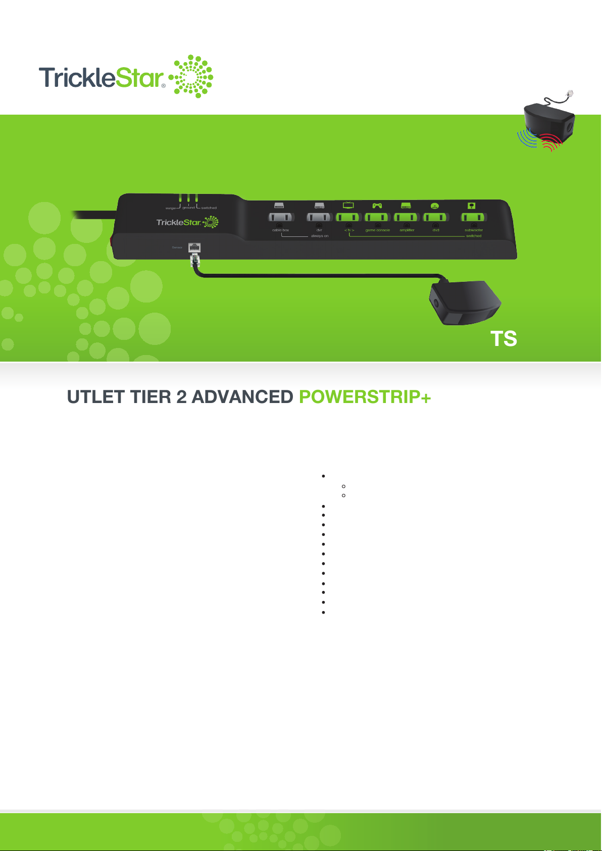
7 OUTLET TIER 2 ADVANCED POWERSTRIP+
ZIGBEE® MULTI-SENSOR
Premium quality, fireproof surge protection that reduces standby and active power waste from electronics
OVERVIEW
The Tier 2 ZigBee® Multi-Sensor Advanced PowerStrip+ (APS+)
provides premium quality surge protection and reduces the amount
of standby and active power wasted by electronics.
The APS+ is designed for use with set-top box systems.
The APS+ includes a low voltage RJ11 port which supports the
connection of a Zigbee
frequency (RF), infrared (IR), and motion.
The APS+ includes advanced power measurement and patented
auto-threshold detection. This allows the APS to accurately support
all types of televisions from old to new high efficiency types. It
provides automation to reduce wasteful standby and active power,
and it is suitable for TV/home theater applications.
In addition to standard power switching, the APS+ also supports “soft
switching” via high-level CEC commands from the multi-sensor to an
HDMI port on the TV; this feature is known as TAV-Link and will result
in placement of connected HDMI devices into a power-saving state
by high-level commands.
®
-enabled multi-sensor that senses radio
KEY FEATURES
7 Outlets
2 Always On Outlets (1 outlet transformer spaced)
5 Switched Outlets (1 outlet transformer spaced)
15A resettable circuit breaker
Auto threshold detection
Intelligently adjusts to new equipment
True RMS power sensing
72,000 Amps/1080 Joules
Ceramic surge protection
Low-voltage, optically-isolated RJ11 input
LED status indication (ground, surge status, switched)
<40dB noice filtering
Angled space saver plug
ZigBee enabled multi-sensor
CEC TAV-Link function
FIREPROOF SURGE PROTECTION
Traditional surge suppression products use standard MOV (metal oxide
varistor) components. TrickleStar Tier 2 APS+ incorporates advanced
surge protection technology. The MOVs are encased in ceramic and
are capable of suppressing more energy and dissipating heat faster
than traditional MOVs. More importantly, the ceramic casing is fireproof
and therefore is capable of preventing fire during surge conditions.
The best way to save energy is to stop wasting it.
PRODUCT WARRANTY
10-year product warranty
$20,000 connected equipment warranty
TM
www.tricklestar.com
Page 2
TIER 2 ZIGBEE
®
ADVANCED POWERSTRIP+
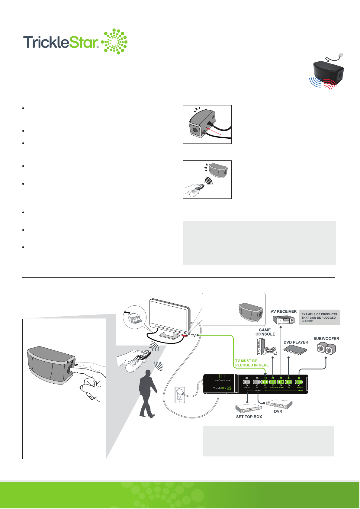
ZIGBEE® MULTI-SENSOR PAIRING DirecTV
REMOTE CONTROL
MULTI-SENSOR
®
or Comcast®
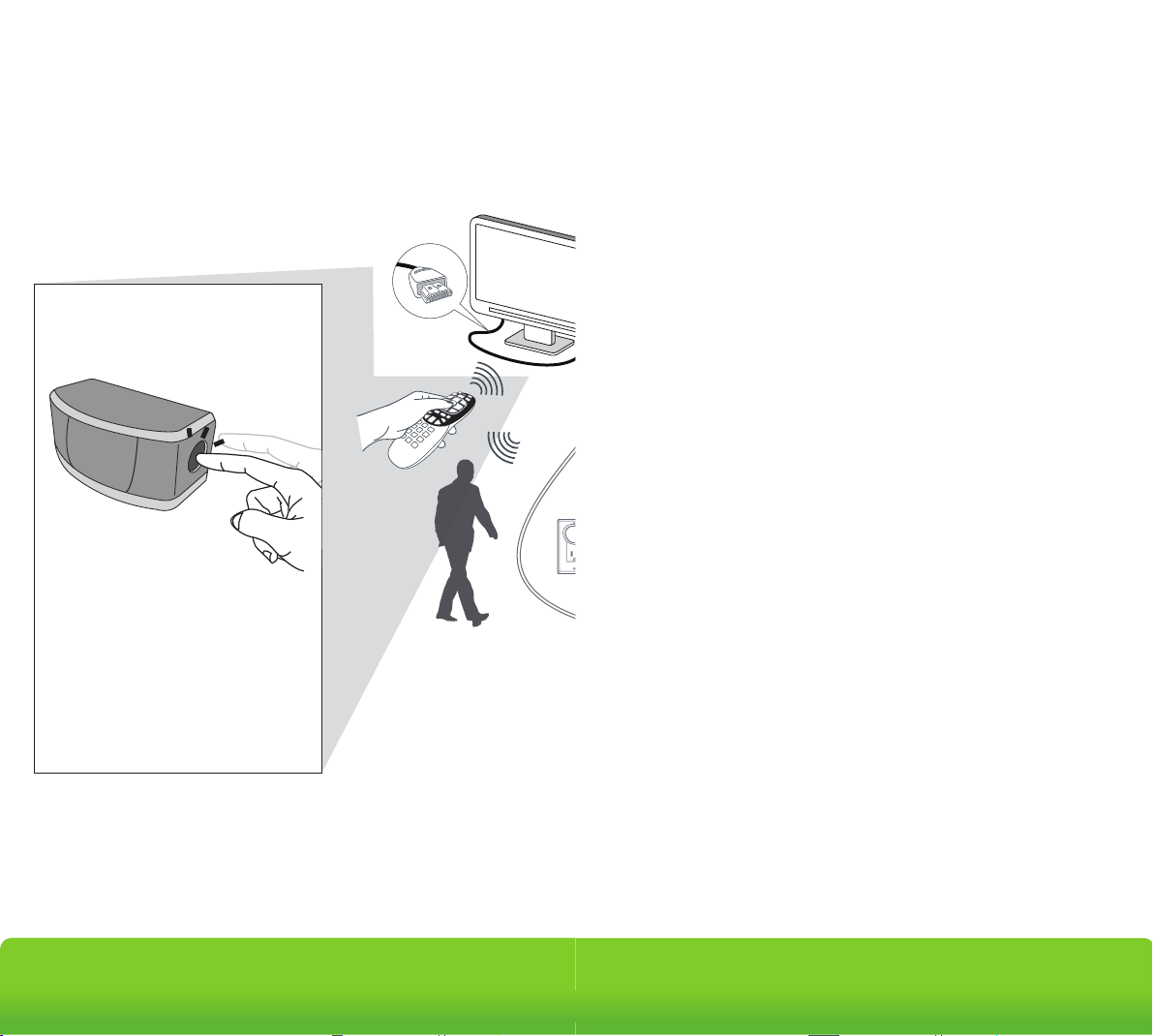
Detects ZigBee RF4CE* RF, IR remote control signals and motion.
Includes a configurable countdown timer that will switch off the
TV and peripherals if no RF, IR or motion is detected.
Status LED flashes when RF, IR or motion is detected.
Patented sensing hardware and algorithm looks for RF and IR
commands first. It then looks for motion after a period where no
RF or IR commands are detected.
Supports high level CEC* commands via TAV-Link cable to the TV
and to the peripherals for soft switch off.
TAV-Link functionality allows “smart” TVs to store their data and
settings safely before powering down. TAV-Link also allows
gaming consoles to enter an energy-saving mode earlier and
without any corruption of data.
®
Supports RF4CE pairing with DirecTV
controls (can pair up to 4 remotes).
Includes a soft chirp, piezo buzzer to warn of a pending shutdown
10 minutes prior to shutdown.
Manual on/off button.
and Comcast® remote
STEP 1
Quickly press the pinhole pairing button
located on the back of the multi-sensor to
trigger the pairing process.
A blue LED will flash for a period of 15
seconds - indicating the multi-sensor is in
pairing mode.
STEP 2
Place the RF4CE DirecTV or Comcast remote
near the sensor (within two inches) and press
the 0 key on the remote until the red LED
illuminates. Repeat with other RF4CE remote
controls (up to four).
The multi-sensor will exit pairing mode after
15 seconds if no RF button presses are
detected.
*RF4CE (Radio Frequency for Consumer Electronics) is a radio frequency
protocol for audio and video device remote controls. It provides two-way,
high-speed communications which allow remote signals to transmit
through cabinets, obstacles, walls and floors.
*CEC (Consumer Electronics Control) is the control protocol found in HDMI.
APPLICATION DIAGRAM
Programming the
Countdown Timer
RF + IR
TV REMOTE
To configure the countdown timer, press
and hold the button for 10 seconds until
the red LED illuminates. Then press:
• Once for 30 minutes
• Twice for 60 minutes
• Three times for 120 minutes
LED will flash once for 30 minutes, twice
for 60 minutes (default setting) and three
times for 120 minutes.
TAV-LINK
(for CEC function)
ZIGBEE RF, IR,
& MOTION
MULTI-SENSOR
*
-
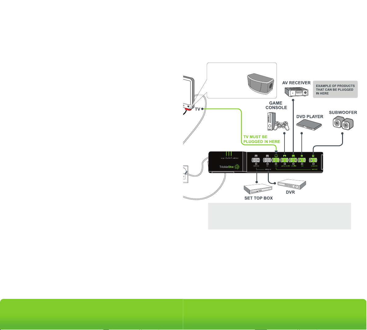
Game consoles without hard disk drives (HDD) should be
*
plugged into a switched outlet. Those with hard disk drives can
be plugged into an always-on outlet and controlled via
TAV-Link.
The best way to save energy is to stop wasting it.
TM
www.tricklestar.com
Page 3
TIER 2 ZIGBEE
Changes or modifications not expressly approved by the party responsible for compliance could void
your authority to operate the equipment.
ADVANCED POWERSTRIP+
®
MULTI-SENSOR
ELECTRICAL SPECIFICATIONS
TIER 2 APS+
FOR INDOOR USE
Operating Voltage
Output Current
Maximum Total Load
Noise Filtering
Power Consumption
RJ11
APS+ Cord Length
Outlets (7 Outlets)
120 VAC +/- 10% 60Hz
15 Amps RMS
1800W
<40dB
<1W at 120VAC, 60Hz
(in all modes of operation)
3.3V & Optically Isolated
4 ft. (1.2 meters)
2 Always ON
(1 outlet transformer spaced)
5 Switched Outlets
(1 outlet transformer spaced)
LED Status Indication
Surge Protection
Ground, Surge, Switched
72,000 Amps / 1080 Joules for all
outlets (Ceramic Surge Protection)
Input Current
15A Resettable Circuit Breaker
MULTI SENSOR
FOR INDOOR USE
Voltage
IR Detection Angle/Range
PIR Detection Angle/Range
RF Detection Range
Cord Length
Sensor Detection
3.3V
60°/Up to 16.4 ft. (5 meters)
90°/Up to 16.4 ft. (5 meters)
360°/Up 16.4 ft. (5 meters)
8 ft.
Infrared, Passive Infrared
and ZigBee RF4CE
PHYSICAL SPECIFICATIONS
Operating Temperature
Storage Temperature
Humidity
IP Rating
32° to 113° F
14° to 140° F
5 to 90% N/C
IP20
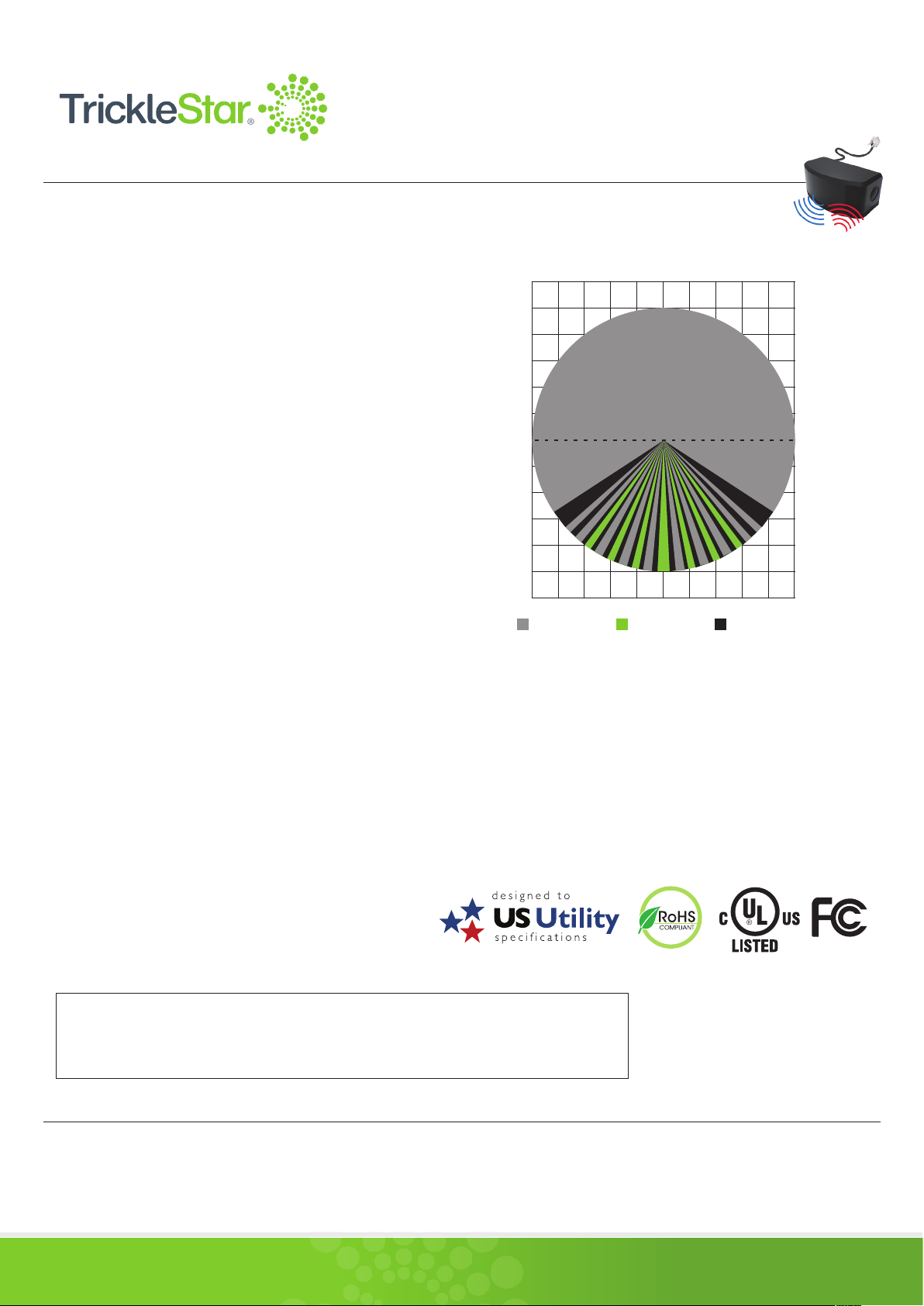
PIR & IR DETECTION PATTERN
SENSOR OPTICAL VIEW PATTERN
16.40 ft. 13.12 ft. 9.84 ft. 6.56 ft. 3.28 ft.
19.69 ft.
16.40 ft.
13.12 ft.
9.84 ft.
6.56 ft.
3.28 ft.
0
3.28 ft.
6.56 ft.
9.84 ft.
13.12 ft.
16.40 ft.
19.69 ft.
RF Detection
Range: 16.4 ft.
Degree: 360°
0 3.28 ft. 6.56 ft. 9.84 ft. 13.12 ft. 16.40 ft.
IR Detection
Range: 16.4 ft.
Degree: 60°
PIR Detection
Range: 16.4 ft.
Degree: 90°
APPROVALS
Conformity to product standards for safety and EMC
UL (US & Canada), 2002/95/EG (RoHs), 2002/96/EC (WEEE),
1999/5/EC (RTTE), FCC Approved, ZigBee Certified
ORDER INFORMATION
7 Outlet APS+, 1080 Joules,
TS1811
4 ft. Cord, Auto Threshold,
Zigbee Multi-Sensor, TAV-Link
19.69 ft.
16.40 ft.
13.12 ft.
9.84 ft.
6.56 ft.
3.28 ft.
0
3.28 ft.
6.56 ft.
9.84 ft.
13.12 ft.
16.40 ft.
19.69 ft.
This device complies with Part 15 of the FCC Rules. Operation is subject to the following two conditions:
(1) this device may not cause harmful interference, and
(2) this device must accept any interference received, including interference that may cause undesired operation.
Copyright © TrickleStar. All rights reserved.
TrickleStar® is a registered trademarks of TrickleStar Ltd. All other trademarks are the property of their respective owners. The information in this document is subject to change without notice.
TrickleStar assumes no responsibility for any errors that may appear in this document.
REV 5 Jan 2016
The best way to save energy is to stop wasting it.
TM
www.tricklestar.com
Page 4
®
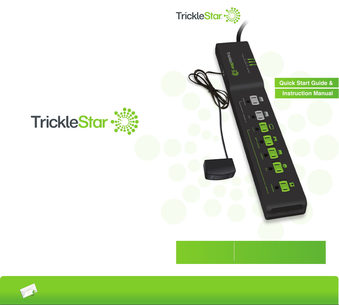
Quick Start Guide &
Instruction Manual
®
Copyright© TrickleStar LLC 2016. All rights reserved.
TrickleStar® is a registered trademark of TrickleStar Ltd. All other trademarks are the
property of their respective owners. The information in this document is subject to
change without notice.TrickleStar assumes no responsibility for any errors that may
appear in this document.
For technical support
go to www.tricklestar.com
or call 1-888-700-1098
PRODUCT INFORMATION
TS1811
7 Outlet Advanced PowerStrip+,
1080 Joules, 4 ft. Cord, Auto Threshold,
Zigbee Multi-Sensor, TAV-Link
www.tricklestar.com
Page 5
Installation
Go to: www.tricklestar.com and print our claim form and email it to
Programming the
Countdown Timer
To configure the countdown timer, press
and hold the button for 10 seconds until
the red LED illuminates. Then press:
• Once for 30 minutes
• Twice for 60 minutes
• Three times for 120 minutes
LED will flash once for 30 minutes, twice
for 60 minutes (default setting) and three
times for 120 minutes.
TAV-LINK
(for CEC function)
IR AND RF
TV REMOTE
7
Advanced
Outlet
This Product is not for use with aquariums and all other water-related products. Use only
indoors and in dry locations. The Connected Device Warranty only protects against
damage to properly connected devices where TrickleStar has determined, in its sole
discretion, that the damage resulted from an occurrence, and does not protect against acts
of God (other than lightning) such as flood, earthquake, war, vandalism, theft, normal-use
wear and tear, erosion, depletion, obsolescence, abuse, damage due to low voltage
disturbances (i.e. brownouts or sags), non-authorized program, or system devices
modification or alteration. This warranty contains the sole warranty of TrickleStar, there are
no other warranties, expressed or, except as required by law, implied, including the implied
warranty or condition of quality, merchantability or fitness for a particular purpose, and
RF + IR + MOTION
such implied warranties, if any, are limited in duration to the term of this warranty. Some
+ DIRECTV
states do not allow limitations on how long an implied warranty lasts, so the above
MULTI-SENSOR
limitations may not apply to you.
In no event shall TrickleStar be liable for incidental, special, direct, indirect, consequential
or multiple damages such as, but not limited to, lost business or profits arising out of the
sale or use of any Product, even if advised of the possibility of such damages. This
warranty gives you specific legal rights, and you may also have other rights, which may
vary from state to state. Some states do not allow the exclusion or limitation of incidental
or consequential damage, so the above limitations may not apply to you.
This warranty is valid only for the original purchaser of the product. All damage claims
against the product must be made within 15 days from the date of the occurrence and
must be accompanied by a receipt for the damaged devices or the warranty is void.
Warranty is valid in USA and Canada.
*
PowerStrip+
MAKING A WARRANTY CLAIM
Provide the following information:
• Product part number
• A list of the devices that were connected to the Product at the time of the
occurrence
• A list of the devices that were damaged during the occurrence and the extent of the
damage
• The date of the occurrence
• Where you purchased the Product
• When you purchased the Product
• A copy of original receipt
A customer service representative will then instruct you on how to forward your devices,
receipt and Product in use during the “occurrence” and how to proceed with your claim.
Game consoles without hard drives are recommended to be
*
plugged into a switched outlet.
Those with hard drives can be plugged into an always on outlet
and controlled via TAV-LINK
-
www.tricklestar.com
COPYRIGHT & DISCLAIMER
© Copyright TrickleStar Ltd. All rights reserved.TrickleStar® is a registered trademark of
TrickleStar. Any typographical, clerical or other error or omission in this document or other
documents or information issued by TrickleStar shall be subject to correction without any
liability on the part of TrickleStar without notice.
REV 5 Jan 2016
Advanced Powerstrip+
Advanced Powerstrip+
Page 6
Product Warranty
This Product is not for use with aquariums and all other water-related products. Use only
indoors and in dry locations. The Connected Device Warranty only protects against
damage to properly connected devices where TrickleStar has determined, in its sole
discretion, that the damage resulted from an occurrence, and does not protect against acts
of God (other than lightning) such as flood, earthquake, war, vandalism, theft, normal-use
wear and tear, erosion, depletion, obsolescence, abuse, damage due to low voltage
disturbances (i.e. brownouts or sags), non-authorized program, or system devices
modification or alteration. This warranty contains the sole warranty of TrickleStar, there are
no other warranties, expressed or, except as required by law, implied, including the implied
warranty or condition of quality, merchantability or fitness for a particular purpose, and
such implied warranties, if any, are limited in duration to the term of this warranty. Some
states do not allow limitations on how long an implied warranty lasts, so the above
limitations may not apply to you.
In no event shall TrickleStar be liable for incidental, special, direct, indirect, consequential
or multiple damages such as, but not limited to, lost business or profits arising out of the
sale or use of any Product, even if advised of the possibility of such damages. This
warranty gives you specific legal rights, and you may also have other rights, which may
vary from state to state. Some states do not allow the exclusion or limitation of incidental
or consequential damage, so the above limitations may not apply to you.
This warranty is valid only for the original purchaser of the product. All damage claims
against the product must be made within 15 days from the date of the occurrence and
must be accompanied by a receipt for the damaged devices or the warranty is void.
Warranty is valid in USA and Canada.
MAKING A WARRANTY CLAIM
Go to: www.tricklestar.com and print our claim form and email it to
warranty@tricklestar.com
Provide the following information:
• Product part number.
• A list of the devices that were connected to the Product at the time of the
occurrence.
• A list of the devices that were damaged during the occurrence and the extent of the
damage.
• The date of the occurrence.
• Where you purchased the Product.
• When you purchased the Product.
• A copy of original receipt.
A Customer Service Representative will then instruct you on how to forward your devices,
receipt and Product in use during the “occurrence” and how to proceed with your claim.
COPYRIGHT & DISCLAIMER
© Copyright TrickleStar Ltd. All rights reserved.TrickleStar® is a registered trademark of
TrickleStar. Any typographical, clerical or other error or omission in this document or other
documents or information issued by TrickleStar shall be subject to correction without any
liability on the part of TrickleStar without notice.
REV 17/12/15
Advanced Powerstrip+
surge ground switched
Installation
The lifetime of the product (hereafter referred to as “Product Lifetime”), is 10 years.
TrickleStar warrants to the original purchaser that for the Product Lifetime, it shall be free
of defects in design, assembly, material, or workmanship, and will repair or replace, at its
option, any defective product free of charge.
CONNECTED DEVICE WARRANTY
TrickleStar will repair or replace, at its option, any devices which are damaged by a
transient voltage surge/spike or lightning strike, (an “Occurrence”), while properly
connected through the Product to a properly wired AC power line with protective
grounding.
If applicable, the telephone line, and/or network line must be properly connected and
installed, and the antenna cable line must also be properly connected and installed, as
determined by TrickleStar at its sole discretion.
Programming The
This Connected Device Warranty is a limited warranty, subject to the limitations and
Countdown Timer
exclusions set forth herein. TrickleStar will repair or replace the damaged connected
devices, at TrickleStar’s option, an amount equal to the fair market value of the damaged
devices or the original purchase price of the devices, whichever is less, up to the maximum
of $20,000.
The fair market value of the devices shall be the current value of the devices specified in
the most recent edition of the Orion Blue Book by Orion Research Corporation, Roger
Rohrs Publisher.
TrickleStar reserves the right to review the damaged Product, the damaged devices, and
the site where the damage occurred. All costs of shipping the Product and the damaged
devices to TrickleStar for inspection shall be borne solely by the purchaser. TrickleStar
reserves the right to negotiate the cost of repairs. If TrickleStar determines, in its sole
discretion, that it is impractical to ship the damaged devices to TrickleStar, TrickleStar may
designate, in its sole discretion, a repair facility to inspect and estimate the cost to repair
Press and hold the operation On/Off
such devices. The cost, if any, of shipping the devices to and from such repair facility and
button for 10 seconds. Then press:
of such estimate shall be borne solely by the purchaser.
- Once for 30 minutes
- Twice for 60 minutes
Damaged devices must remain available for inspection until the claim is finalized.
- Thrice for 120 minutes
Whenever claims are settled, TrickleStar reserves the right to be subrogated under any
existing insurance policies the claimant may have. All above warranties are null and void
LED will flash once for 30 minutes, twice
if:
for 60 minutes (default setting) and
• The Product in use during the occurrence is not provided to TrickleStar for inspection
thrice for 120 minutes.
upon TrickleStar ’s request at the sole expense of the purchaser.
• TrickleStar determines that the Product has not been installed in accordance with the
Installation Requirements, altered in any way or tampered with.
• TrickleStar determines that the damage did not result from the occurrence or that no
occurrence in fact took place, the repair or replacement of the damaged devices is
covered under a manufacturer’s warranty.
• TrickleStar determines that the connected devices were not used under normal
operating conditions or in accordance with any labels or instructions.
• The Product is not plugged directly into a receptacle.
• The Product is “daisy-chained” together in serial fashion with other power boards,
Uninterruptible Power Supplys, other surge protectors or extension cords.
• A three-to two-prong adapter is used.
• The Product is not used indoors.
TAV-LINK
(for CEC function)
IR AND RF
TV REMOTE
7
Advanced
Outlet
ZIGBEE RF, IR, &
MOTION
MULTI-SENSOR
*
PowerStrip+
Game consoles without hard disk drives (HDD) should be
*
plugged into a switched outlet. Those with hard disk drives can
be plugged into an always-on outlet and controlled via
TAV-Link.
-
www.tricklestar.com
www.tricklestar.com
Advanced Powerstrip+
Page 7
switched
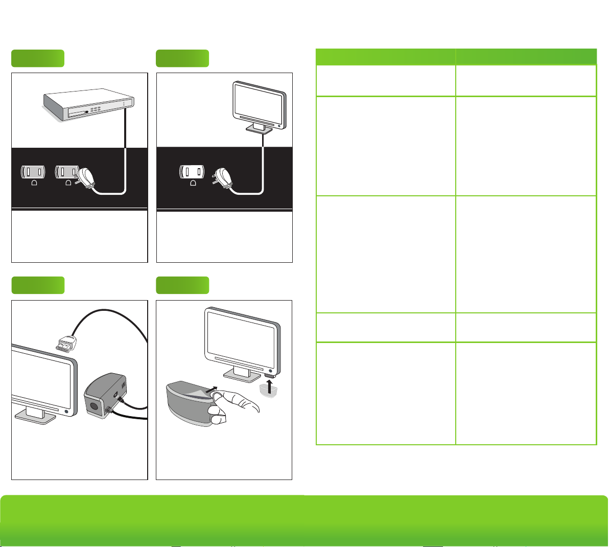
Step 7
Plug the power strip into a grounded
receptacle. The ground and surge
lights will illuminate indicating proper
grounding and surge protection is
functional.
Installation
Step 4
Plug the multi-sensor into the port on
the side of the power strip that looks
like a phone jack.
Step 3
switched
dvd
cable box
game console
amplifier
< tv >
subwoofer
The icons on the outlet strip serve
ONLY as examples of home
entertainment devices that can be
plugged into these outlets. For
example, a DVD may be plugged into
any of the four outlets as they all
operate the same.
always on
ground
surge
sensor
swiched
Advanced Powerstrip+
Advanced
PowerStrip+
Outlet
7
surge ground switched
Troubleshooting
7
Advanced
Outlet
PowerStrip+
always on
Plug in devices that should always
have power to them into the always-on
outlets. Eg. DVR and set-top boxes.
Step 5
Plug the TAV-Link cable into the HDMI
port on the TV if you have a smart TV
or HDMI connected peripherals.
- OPTIONAL
Step 2Step 1
< tv >
< tv >
TV must be plugged into this outlet.
Step 6
Remove the backing from the double
sided tape on the back of the
multi-sensor & affix to or near the TV.
Problem Solution
No power to outlets
The resettable switch must be at
the reset position.
No power at switched outlets
The multi-sensor must be
connected to the APS+ and RF or
IR signal from any remote must be
received to switch on the switched
outlets.
Alternatively, press the button on
the multi-sensor to switch on
The TV peripherals do not switch
off when the TV is off
switched outlets manually.
Make sure that the TV is plugged
into the outlet with the green TV
icon.
Make sure that the TV peripherals
are connected to the green
switched outlets (except for TV).
The switched outlets will switch off
after the TV has been switched off
for one minute.
The multi-sensor is blinking on and
off every 5 seconds
The TV keeps switching off after
30/60/120 minutes
This is a notification that your TV
will shut off in 10 minutes.
The power saving/countdown
timer shuts off the TV and
peripherals after 30/60/120
minutes if no RF/IR signal or
motion is sensed. To reset the time
for another 30/60/120 minutes,
press a button on an RF/IR remote
control or move in front of the
multi-sensor.
www.tricklestar.com
Advanced Powerstrip+
Page 8
Trouble Shooting
FAQ
No power to outlets
No power at switched outlets
The TV peripherals do not switch
off when the TV is off
The multi-sensor is blinking on and
off every 5 seconds
The TV keeps switching off after
30, 60, 120 minutes
The resettable switch must be at
the reset position.
The multi-sensor must be
connected to the APS+ and RF or
IR signal from any remote must be
received to switch on the switched
outlets.
Alternatively, press the button on
the multi-sensor to switch on
switched outlets manually.
Make sure that the TV is plugged
into the outlet with the green TV
icon.
Make sure that the TV peripherals
are connected to the green
switched outlets (except for TV).
The switched outlets will switch off
after the TV has been switched off
for 1 minute.
This is a notification that your TV
will shut off in 10 minutes.
The power saving / countdown
timer shuts off the TV and
peripherals after 30 / 60 / 120
minutes if no RF/IR signal or
movement is sensed. To reset the
time for another 30 / 60 / 120
minutes, press a button on an
RF/IR remote control or move in
front of the multi-sensor.
Problem Solution
Advanced Powerstrip+
Advanced
PowerStrip+
Outlet
7
cable box
< tv >
always on
ground
surge
sensor
swiched
7
Advanced
Outlet
PowerStrip+
What can I plug into the APS+?
Never insert any object other than a plug into the APS+ outlets.
The APS+ is designed for use with indoor AV equipment. Do not use
outdoors.
Never use the APS+ for appliances other than AV equipment, such as a
fridge, electric kettle, electric oven or microwave.
Never use the APS+ for power tools such as power drills, bench saws and
other power tools.
What AV equipment should I plug into the grey always on outlets?
Plug in Audio Visual (AV) equipment that need constant power for recording
features, timers and program guides such as:
• TiVo
• DVD recorders
• Devices with a hard disk drive (HDD)
• Digital receivers
• Set-top boxes
• Game console with a HDD
What AV equipment should I plug into the switched outlets?
The TV must be plugged into the green outlet labelled < tv >. Plug in devices
such as the following to the remaining switched outlets:
• Blu-ray, DVD and CD player
• Amplifiers
• Game consoles without a HDD
• Home theatre speaker systems
How does the APS+ save energy?
The APS+ saves energy through:
1) Master control
• All switched outlets are automatically switched off within one minute after
the TV is switched off.
2) Energy saving feature
• In TV mode all switched outlets are automatically switched off after
135 minutes if there is no RF, IR remote control signal or movement
detected.
• In music mode all switched outlets are automatically switched off after
eight hours if there is no RF, IR remote control signal or movement is
detected.
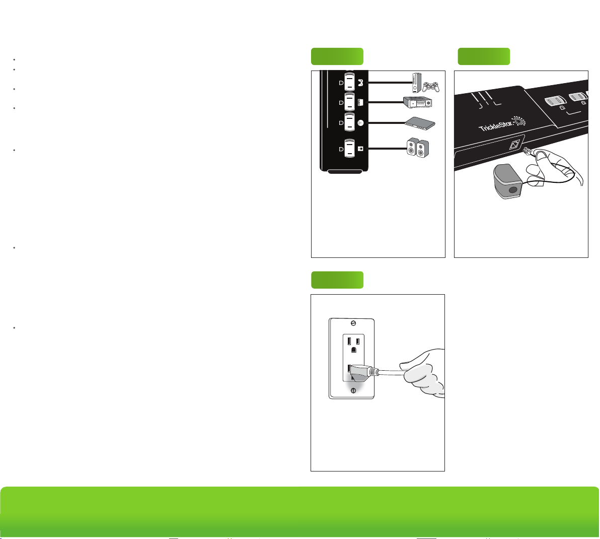
Step 3
game console
Step 4
amplifier
dvd
switched
subwoofer
The icons on the outlet strip serve
ONLY as examples of home
entertainment devices that can be
plugged into these outlets. For
example, a DVD may be plugged into
any of the four switched outlets as they
all operate the same.
Plug the multi-sensor into the port on
the side of the power strip that looks
like a phone jack.
Step 7
Plug the power strip into a grounded
receptacle. The ground and surge
lights will illuminate - indicating proper
grounding and surge protection is
functional.
www.tricklestar.com
Advanced Powerstrip+
Page 9
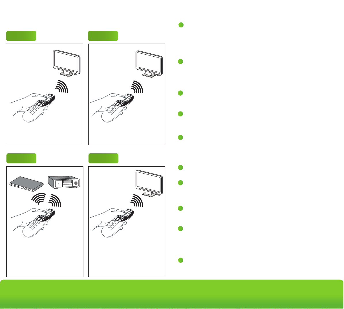
Operation - TV Mode
ON
OFF
Advanced Powerstrip+
Advanced
PowerStrip+
Outlet
7
Energy Saving
Countdown Timer Operation
For the first 15 / 30 / 60 minutes - the multi-sensor senses for RF/IR only
For the next 15 / 30 / 60 minutes - the multi-sensor senses for RF/IR signal or
movement
After 30 / 60 / 120 minutes if no RF/IR or movement has been
sensed the switched outlets willl switch off automatically.
Switched Outlets
Switch On
User Switches
TV On
15, 30, 60 min Countdown Timer
Starts
RF + IR Remote Control Button
Press Detected?
Next 15, 30, 60 min Countdown
Timer Starts
RF/IR Or Movement
Detected
TV + Peripherals
Switch Off
No
No
Yes
Yes
ALERTS START
10 min Before Countdown
Timer Expiry
Buzzer Sounds 3X
LED Flashes
Terms
IR
IR Signal Sensor
PIR Sensor
Movement
Countdown Timer
Countdown Period
LED
Buzzer
Infrared signal, transmitted by a remote control
Multi-sensor senses for an IR command
Multi-sensor uses passive Infrared sensing to
detect movement
Movement detected by PIR
Time before the switched outlets are automatically
switched off
30 minutes / 60 minutes (default) / 120 minutes
Red LED located in multi-sensor
When IR or movement is sensed, the LED will flash
Buzzer located in the multi-sensor
-
RF
Radio frequency, transmitted by a remote control
-
-
-
-
-
-
-
-
-
User Presses RF/IR
Remote Control
Press any button on TV remote control
to turn on the switched outlets.
Step 3
Use peripheral RF/IR remotes to turn
on peripherals as needed.
Step 2Step 1
Press power on TV remote control to
turn on TV.
Step 4
When done watching TV, press the
power button on the TV remote control
to switch off the TV. All switched outlets
will then automatically turn off within
one minute.
7
RF/IR + Movement Multi-Sensor
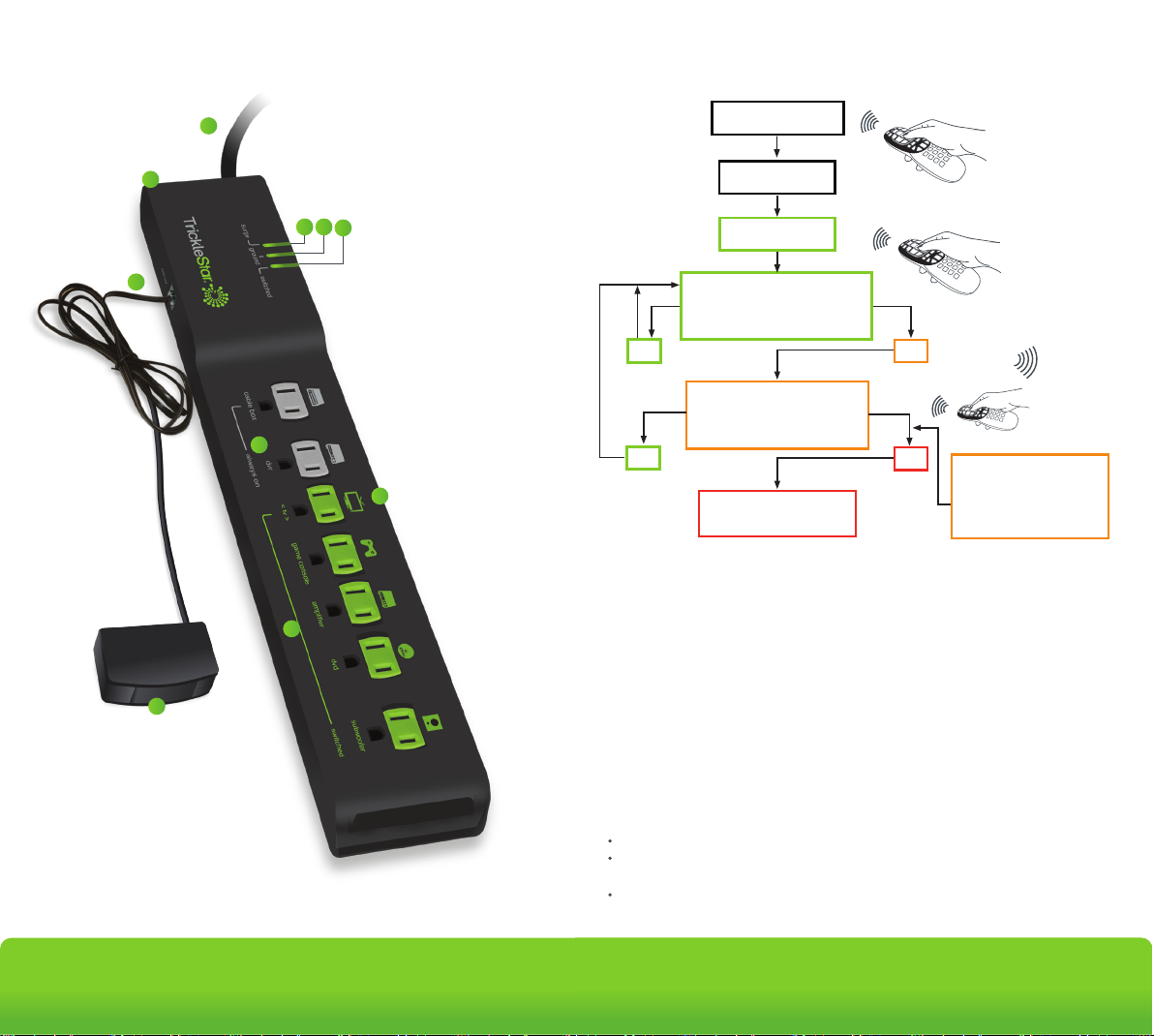
1
The Zigbee multi-sensor is connected to the powerstrip via the RJ11 port
marked “sensor.” Mount the ZigBee multi-sensor on the underside of the TV,
near the IR receiver on the TV (typically located next to the TV's power on/off
button). The multi-sensor must be located within line of sight of where you
normally use your remote controls.
Power Connection
2
The Product must only be plugged into a grounded receptacle for surge
protection to operate correctly. All connected devices should be plugged
directly into the Product. Use of an extension cord, adaptor or other powerstrip
in conjunction with the Product will void all warranties.
Sensor/RJ11 Port
3
Plug the RF/IR & motion multi-sensor into this port.
There will be a soft audible ‘click’ when the connector is inserted correctly.
Surge LED
4
When illuminated, it indicates that the surge protection is functioning normally.
If this LED illuminates red or extinguishes at any time, the Product was
sacrificed to protect your devices and must be replaced.
5
Ground LED
When illuminated, it indicates that the Product is correctly grounded.
If not illuminated, there is a grounding problem and you must contact an
electrician to properly ground the socket. Surge protection will not work with an
improperly grounded outlet.
Switched Outlets LED
6
When illuminated, it indicates that the switched outlets are receiving power.
Resettable Circuit Breaker
7
All outlets on the Product are protected. If the surge, ground, and switched
LEDs are not illuminated and/or connected devices are not receiving power,
switch the circuit breaker to activate power.
Always-On Outlets
8
Equipment that requires continuous power should be plugged into the
always-on outlets.
< tv > Outlet
9
The outlet marked <tv> is the control outlet and includes true RMS power
measurement.
IMPORTANT
THE TV MUST BE PLUGGED INTO THIS OUTLET
10
Switched Outlets
If there is no RF, IR, or motion detected, these outlets will switch off.
Advanced
Outlet
PowerStrip+
www.tricklestar.com
Advanced Powerstrip+
Page 10
4
5
Ground LED
When illuminated, it indicates that the Product is correctly grounded.
If not illuminated, there is a grounding problem and you must contact an
electrician to properly ground the socket. Surge protection will not work
with an improperly grounded outlet.
Surge LED
When illuminated, it indicates that the surge protection is functioning
normally. If this LED illuminates red or extinguishes at any time, the
Product was sacrificed to protect your devices and must be replaced.
6
7
Switched Outlets LED
When lit, it indicates that the Outlets are powered.
Resettable Circuit Breaker
Provides protection for all Outlets on the product. If no devices are
powered or LEDs lit, press the circuit breaker to activate power.
8
Always On Outlets
Outlets remain ON all the time.
9
< tv > Outlet
The Outlet includes True RMS Power Measurement outlet for TV.
IMPORTANT
THE TV MUST BE PLUGGED INTO THIS OUTLET
Switched Outlets
Switched off if there is no RF, IR or movement is detected, or if the TV is
switched off.
1
2
3
RF/IR + Movement Multi-Sensor
The ZigBee multi-sensor is connected to the powerstrip via the RJ 11 port
- marked “sensor”. Mount the ZigBee multi-sensor on the underside of the
TV, near to the IR receiver on the TV. Typically located next to the TV
power on/off button. The multi-sensor must be located within line of sight
of where you normally use your remote controls.
Power Connection
The Product must only be plugged into a grounded receptacle for surge
protection to operate correctly. All connected devices should be plugged
directly into the Product. Use of an extension cord, adaptor or other
powerstrip in conjunction with the Product will void all warranties.
Sensor/RJ11 Port
Plug the RF / IR + Movement multi-sensor into this port.
There will be a soft audible ‘click’ when the connector is inserted correctly.
Advanced Powerstrip+
Advanced
PowerStrip+
Outlet
7
Product Overview
10
2
7
3
1
7
Advanced
Outlet
PowerStrip+
4 5
Energy Saving
6
User Presses RF/IR
Remote Control
Switched Outlets
Switch On
User Switches
TV On
Yes
8
9
Yes
15/30/60 Min Countdown Timer
RF + IR Remote Control Button
Next 15/30/60 Min Countdown
Starts
Press Detected?
Timer Starts
RF/IR or Motion
Detected
TV & Peripherals
Switch Off
No
No
10 Min Before Countdown
ALERTS START
Timer Expiry
Buzzer Sounds 3X
LED Flashes
Terms
IR
IR Signal Sensor
10
PIR Sensor
RF
Motion
Countdown Timer
Countdown Period
LED
Buzzer
Countdown Timer Operation
For the first 15/30/60 minutes - the multi-sensor senses for RF/IR only.
For the next 15/30/60 minutes - the multi-sensor senses for RF/IR signal or
motion.
If no RF/IR or motion has been sensed during the 30/60/120 minute countdown
period, the switched outlets will switch off automatically.
-
Infrared signal, transmitted by a remote control
-
Multi-sensor senses for an IR command
-
Multi-sensor uses passive Infrared sensing to
detect movement
-
Radio frequency, transmitted by a remote control
-
Motion detected by PIR
-
Time before the switched outlets are automatically
switched off
-
30/60/120 minutes (default - 60 min.)
-
Red LED located in multi-sensor
-
When IR or motion is sensed, the LED will flash
-
Buzzer located in the multi-sensor
www.tricklestar.com
Advanced Powerstrip+
Page 11
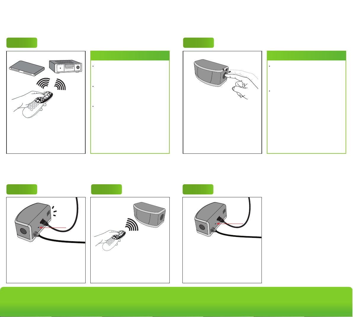
Operation - Music Mode
Operation -
Operation Countdown Timer Setting
7
Advanced
Outlet
PowerStrip+
Step 1
Step 1
Note
If the TV is not switched on at any time
in between, all switched outlets will
turn off after eight hours.
If any RF/IR signal is detected, the
countdown timer period will
automatically reset for another eight
hours.
If the TV is switched on during music
mode, the Advanced PowerStrip+ will
Press any button on AV receiver or
DVD/CD player remote control to turn
on the switched outlets.
Press power on all music related
devices to switch them on.
switch to TV mode.
Operation RF Remote Control and Pairing
To configure the countdown timer,
press and hold the button for 10
seconds until the red LED illuminates.
Then press:
• Once for 30 minutes
• Twice for 60 minutes
• Three times for 120 minutes
After countdown timer is set, the LED
will flash the number of times that
timer has been set to.
Operation Delete Paired RF Remote Control Address
Step 1 Step 2 Step 1
Note
The sensor has a default buzzer
notification that will sound three times
during the 10 minute countdown
timer period.
To disable the audible notification,
press and hold the button for 10
seconds until the red LED
illuminates, then press the button four
times. The red LED will flash four
times to confirm the countdown timer
buzzer has been disabled.
Quickly press the pinhole pairing
button located on the back of the
multi-sensor to trigger the pairing
process.
A blue LED will flash for a period of 15
seconds - indicating the multi-sensor
is in pairing mode.
www.tricklestar.com
Place the RF remote control near the
sensor (within two inches) and press
the 0 key on the remote until the red
LED on the sensor illuminates. Repeat
with other RF remote controls (up to
four).
Press and hold the pin-hole pairing
button for five seconds.
Blue LED will illuminate for one
second - indicating all paired remote
control addresses have been erased.
Advanced Powerstrip+
 Loading...