

Page 1

Visor Cooker Hood - CH 520 and CH 610
Operating and Installation Instructions
Page 2

CONTENTS
Please refer to the sections in this booklet that apply to your particular model: Page
CONTENTS 1
WARNINGS 2
GENERAL 3
INSTALLATION INSTRUCTIONS ELECTRICAL CONNECTION 4
UNPACKING 5
POSITIONING 5
WALL FITTING 5
WALL CABINET FITTING 6
DUCTING FITTING 6
OPERATING INSTRUCTIONS 7
DO’S AND DON’TS 7
MAINTENANCE AND CLEANING WORKTOP LIGHTING 8
MAINTENANCE AND CLEANING FILTERS 8
HELP US TO HELP YOU 9
TECHNICAL SPECIFICATIONS
DIMENSIONS CH520 Width cm 49.8
CH610 Width cm 59.8
Height cm 15.0
Depth cm 48.0
Depth with visor open cm 53.0
WEIGHT CH520 Gross kg 8.2
Net kg 7.2
CH610 Gross kg 8.7
Net kg 7.7
ELECTRICAL CONNECTION Voltage 220-240V ~ 50Hz
Fan 110W
Lamps 2x40W 80 W
Total Consumption 190W
PERFORMANCE Speed 1 2 3
Capacity m
3
/h 130 180 250
Capacity lt/sec 36 50 69
Pressure mmH
Noise level dbA 45 51 59
O10 1825
2
1
Page 3

WARNINGS WARNINGS
It is most important that this instruction
book should be retained with the appliance
for future reference. Should the appliance
be sold or transferred to another owner, or
should you move house and leave the
appliance always ensure that the book is
supplied with the appliance in order that
the new owner can be acquainted with the
functioning of the appliance and the
relevant warnings. Please ensure that you
have read the whole instruction book before
using the appliance and that you follow the
recommendations given.
These warnings are provided in the interest
of safety. They must be read carefully
before installing or using this appliance.
This appliance is designed to be operated by
adults. Children should not be allowed to
tamper with the controls or play with the
product.
It is dangerous to alter the specifications or
modify the product in any way.
Any installation work must be undertaken by
a qualified electrician or a competent person.
This product should be serviced by an
authorised Tricity Bendix Service Centre, and
only genuine Tricity Bendix spare parts should
be used.
Never leave frying pans unattended during use
as overheated fats and oils may catch fire.
Never do flambe cooking under this cooker
hood.
It is a possible fire hazard if the grease and
charcoal filter are not replaced as
recommended.
When used in the extraction mode the cooker
hood must not be connected to a flue which is
used for exhausting fumes from appliances
supplied with energy other than electric such
as a central heating flue or water heater.
If the room where the cooker hood is to be
used contains a fuel burning appliance such
as a central heating boiler then its flue must
be of the room sealed or balanced flue type.
If other types of flue or appliances are fitted
ensure that there is an adequate supply of air
to the room.
All installations must comply with the local
authorities requirements for the discharge of
exhaust air.
If the hood is installed for use above a gas
appliance then the provision for ventilation
must be in accordance with the Gas Safety
(Installation & Use) Regulations 1994 No.1886
and the relevant building regulations. Details
are contained in the following British Standard
Codes of Practise BS.6172 BS.5440 and
BS.6891 Current Edition.
The fan motor of this cooker hood incorporates
a thermal cut-out device which will operate if
the cooker hood is installed below the
minimum height recommended in this booklet,
or if the motor becomes overheated. If the
cut-out device is acti-vated, switch off the fan
motor and allow the cooker hood to cool.
The cut-out device will reset itself when the
fan motor has cooled significantly.
This cooker hood has been designed for
installation over an electric hotplate with a
maximum input of 7Kw or a gas hotplate
with a maximum input of 10Kw when fitted
in accordance with the heights
recommended in this booklet.
Under no circumstances should you attempt
to repair the appliance yourself. Repairs
carried out by an inexperienced person may
cause injury or more serious malfunctioning.
Refer to your local Tricity Bendix Service
Centre. Always insist on genuine Tricity Bendix
spare parts.
2
Page 4
GENERAL INFORMATION ELECTRICAL CONNECTION
This instruction book applies to the
following models:
Tricity Bendix CH520B Brown 50cm
Tricity Bendix CH520W White 50cm
Tricity Bendix CH610B Brown 60cm
Tricity Bendix CH610W White 60cm
This cooker hood is guaranteed and will
give lasting service. The guarantee is only
applicable if the hood has been installed in
accordance with the installation instructions
detailed in this booklet.
This cooker hood has been designed for
use fixed beneath a wall cabinet or directly
onto the wall using the special brackets
supplied and should be installed in
accordance with the following fitting
instructions.
The cooker hood can be used to extract
odours to the outside or to recirculate the
air within the kitchen after passing the
contaminated air through a cleansing
charcoal filter which is supplied as
standard.
The cooker hood is convertible to either
function by the movement of a change-over
slider control. This enables the cooker hood
when installed in the extraction mode, to be
converted to recircu-lation during the winter
months.
The installation instructions which follow
give instructions on how and where this
hood may be fitted. If already installed
check with the installer that all the
requirements have been met. If not then
draw these to the attention of the installer
who should be a qualified electrician or a
competent person.
Tricity Bendix disclaims all liability for any
damage or injury caused as a result of not
following the instructions contained in the
following text.
Before connecting to the mains supply ensure that
the mains voltage corresponds to the voltage on
the rating plate inside the cooker hood.
WARNING: THIS APPLIANCE MUST BE
EARTHED
This appliance is fitted with a 3 core mains supply
cable and should be permanently connected to
the electricity supply via a double-pole switch
having 3mm minimum contact gap on each pole.
A Switched Fuse Connection Unit to BS.1363 Part
4 (fitted with a 3A fuse), is a recommended mains
supply connection accessory to ensure compliance with the Safety Requirements applicable to
fixed wiring instructions.
CONNECTION TO THE MAINS POWER
SUPPLY
Any permanent electrical installation must comply
with the latest I.E.E. Regulations and local
Electricity Board regulations. For your own safety
this should be undertaken by a qualified
electrician e.g. your local Electricity Board, or a
contractor who is on the roll of the National
Inspection Council for Electrical Installation
Contracting (NICEIC).
WARNING: INCORRECT INSTALLATION
COULD AFFECT THE SAFETY OF THIS
CHIMNEY HOOD.
DISCONNECT THE HOOD FROM THE MAINS
SUPPLY BEFORE CARRYING OUT ANY KIND
OF MAINTENANCE OR CLEANING.
This appliance conforms to BS.800:1988 and
EEC Directive 87/308 regarding suppression of
radio and television interference.
Width: CH520B - CH520W 498mm
Width: CH610B - CH610W 598mm
3
Page 5

INSTALLATION INSTALLATION
UNPACKING
Care should be taken when unpacking the
cooker hood to ensure that the fixing kit,
ducting spigot, blanking plate and literature
pack are retained with the hood.
The fixing kit comprises:
1- Wall/Suspended fixing template.
2- Wall fixing brackets.
4- Plastic rawl plugs.
4- Wall/Suspended fixing screws.
2- Shakeproof washers.
2- Security nuts.
POSITIONING
When installed above an electric cooking
appliance the minimum distance between the
surface of the hob elements and the lower
grille of the cooker hood must be 65cm (25 1/
2").
When installed above a gas cooking appliance
the minimum distance between the surface of
the hob pan supports and the lower grille of
the cooker hood must be 70cm (27 1/2").
However, if you are installing above a
Tricity Bendix hob the minimum distance
between the surface of the hob elements/
pan supports and the lower grille of the
cooker hood may be reduced to 60cm (23
5/8”)
When installed above a cooking appliance with
a high level grill the minimum distance between
the upper surface of the grill and the lower
grille of the cooker hood must be 45cm (17 3/
4").
The distance between the underside of
adjoining wall cabinets and the worktop must
not be less than 40cm (15 3/4").
WALL FITTING
The cooker hood may be fitted to any rigid
vertical surface. All the fittings supplied are to
be found in a polythene bag inside the carton.
IMPORTANT: Before installation check the wall
to which the cooker hood is to be fitted for
electric cables, water pipes or gas pipes before
drilling.
If it is necessary to fix the hood to a hollow construction plaster or partition board structure
then it must be sufficiently reinforced to be quite
rigid in the area of the cooker hood mounting
brackets. The hood must not be fitted using the
key hole fixing points but with the special
brackets supplied.
Use the paper template provided to mark the
hole positions on the wall for the bracket fixing
screws.
Check the hole distances are correct with a
tape measure as stated on the template.
At this stage it is important to allow 15mm (1/
2") clear space above the cooker hood to
enable it to be hooked onto the brackets and
for subsequent removal for decorating or
servicing.
When drilling the holes for the wall fixing
brackets care must be taken to ensure that
they are quite level as there is minimal vertical
height adjustment of the fixing brackets.
The brackets should be fitted with the round
end at the bottom using the plastic rawl plugs
and screws provided.
If the brackets are to be fitted to a hollow
plaster or partition board structure then the
plastic rawl plugs provided should not be used.
Once the brackets are secured lift the hood
squarely to the wall slightly higher than the
brackets and lower the cooker hood until the
cooker hood locates onto the two brackets.
Ensure that the cooker hood is correctly
located before letting go.
Access to the two wall levelling screws and
the security fixing system will require the
removal of the lower inlet grille that supports
the grease mat filter.
To remove the lower grille press inwardly on
the two slide catches located towards either
side of the grille near the front and the grille
will open from the front. The grille pivots at
the rear. Slide the right edge of the grille
forward until it clears the guide and then
unhook the left hinge pin.
Care should be taken to fully support the grille
when removing it from the guides.
The two wall levelling screws will be visible
toward either end of the back panel, visible
when the grille has been removed. Turn the
screws clockwise to lift the front edge of the
hood and use a spirit level to check the hood
is positioned at right angles to the wall before
fitting the security system.
The wall brackets have two studs and when
the cooker hood is hung onto the brackets
the studs project through the two holes above
the levelling screws.
When the hood is level fit the two shakeproof
washers and nuts supplied to fully secure the
cooker hood.
4
Page 6

INSTALLATION Cont’d OPERATING INSTRUCTIONS
WALL CABINET FITTING
Before fitting the cooker hood beneath any
type of wall cabinet ensure it is firmly fixed to
the wall in accordance with the manufacturers
instructions.
Use the paper template provided to mark the
hole positions on the underside of the cabinet.
When marking the underside of the cabinet
the front edge of the template must be aligned
with the front edge of the cabinet carcase.
Check the distances of the holes are correct
with a tape measure as stated on the template.
The four holes are 5mm (1/4") dia.
A pad saw or similar cutter will be required to
cut the circular hole for the ducting spigot if it
is to be used.
Insert the fixing screws through the holes from
inside the cabinet. Supporting the cooker hood
tighten each screw about half way to ensure
that the cooker hood is correctly positioned
before fully tightening the screws.
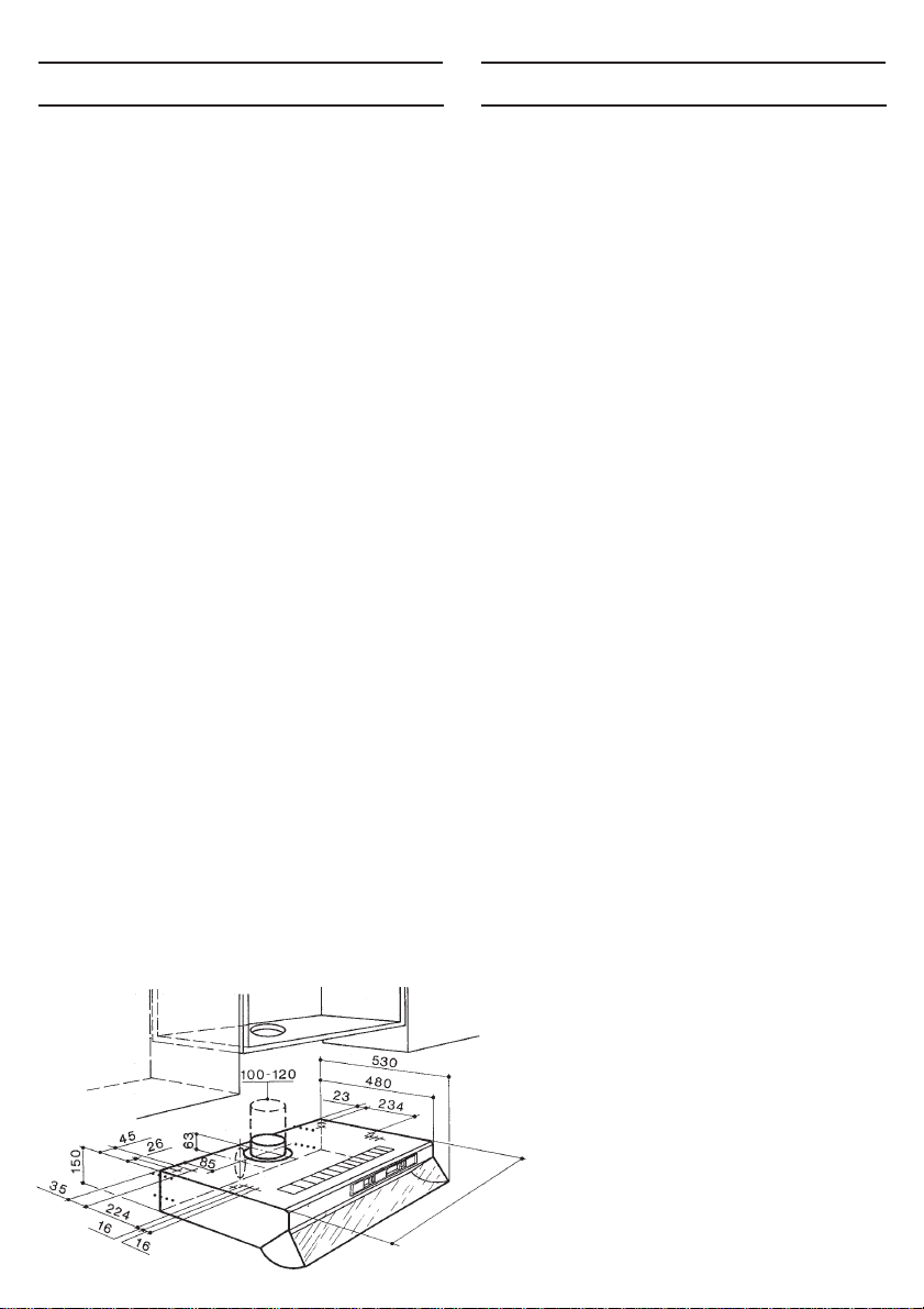
DUCTING FITTING
If the hood is to be ducted to the outside then
the blanking plate supplied must be fitted in
the aperture that will not be used.
Fit the ducting spigot into the selected aperture
and make an air tight connection.
To fit the ducting spigot and blanking plate align
the inter-locking lugs on the fitting with the
recesses in the aperture and insert turning
clockwise to lock the spigot and blanking plate
into position.
The ducting used must be 100mm (4")
diameter and be manufactured from fire
retardent material conforming to the relevant
British Standard or DIN 4102-B1.
The cooker hood functions are controlled by
two slide switches and a change-over slider
control. The two slide switches, which are
located on the right hand side in the front
fascia panel, control the fan speed and
worktop illumination.
The change-over slider control is located inside
the hood behind the inlet grille immediately in
front of the lamp assembly.
Ensure the hood is in, or wired in and the
power supply is switched on.
The switch marked with the lamp symbol and
numbered 0-1 controls the worktop lighting.
Position -1 indicates the light is operating.
The switch marked with the fan symbol and
numbered 0-1-2-3 controls the fan speed, -1
Low, -2 Normal and -3 Boost.
Position -1 Should be selected when
simmering or when using one pan.
Position -2 Should be selected for normal
cooking up to four pans.
Position -3 Should be selected when frying
or cooking food with strong odour.
In the recirculation position, slider towards the
charcoal filter, air enters the cooker hood,
passes through the grease and charcoal filter
and out through the holes in front of the casing
top panel.
To convert the hood from extraction to
recircula-tion open the metal inlet grille and
slide the change-over control to the right.
Remove the thumb screw from the motor
support. Take the charcoal filter and place it
over the motor support and secure by passing
the thumb screw through the hole in the filter
and into the captivated nut in the centre of
the motor support.
In the ducting position, slider away from the
charcoal filter, the air passes through the
grease filter and out through ducting to the
atmosphere. When the ducting position is
selected, the charcoal filter is not required.
Where flexible ducting is fitted it should not
be turned through very tight bends as this
could impair the performance of the hood. (The
maximum length of ducting including one 90
bend should be 3 metres, to be reduced by 1
metre for each 90 degree bend installed in
the duct run).
When the ducting mode is selected the
charcoal filter is not required.
NOTE: The hood is more effective when used
in the extraction (ducting) mode, therefore this
position should be selected during the warmer
o
months of the year when no room heating is
required. When the room is being heated if the
recirculation position is selected heat will not
be wasted.
To obtain the best performance it is advisable
to switch on the hood a few minutes before
you start cooking and leave it running for
approximately 15 minutes after finishing.
5
Page 7

MAINTENANCE MAINTENANCE
DISCONNECT THE HOOD FROM THE
MAINS SUPPLY BEFORE CARRYING OUT
ANY KIND OF MAINTENANCE OR
CLEANING.
WORKTOP LIGHTING
If a lamp fails to function at any time first check
that it is fully screwed into the holder.
When changing the lamp an identical
replacement must be fitted to ensure the safe
working of the cooker hood. Replacement
lamps are specified 230-240Volts 40Watt
clear cylindrical, candle, or tulip shape with
small Edison (E14) screw thread cap.
CLEANING
For your own safety and in the interests of
hygiene your cooker hood needs to be kept
clean. A build up of grease or fat from cooking
could cause a fire hazard.
Never use excessive amounts of water when
clea-ning particularly around the control panel
area.
The metal casing, lower grille assembly and glass
visor should be cleaned at least once a month
to keep it looking like new. Wipe over the hood
with a soft cloth wrung out in hot water and
containing a mild household cleaner and dry with
a soft cloth. Always wear protective gloves when
cleaning the hood.
NOTE: Never use scouring pads or abrasive
cleaners as they might scratch or damage the
surface.
CHARCOAL FILTER
The charcoal filter cannot be cleaned. It should
be replaced at least once every three months
or more frequently if the cooker hood is used
for more than three hours a day.
kept away from children as the wire clips
have sharp points.
IMPORTANT: There could be a possible fire
hazard if the grease and charcoal filters are
not replaced according to these instructions.
For replacement filters please use the order
form enclosed.
DO’S AND DON’TS
Do’s
Do have the visor open when using the hob
even if the fan on the hood is not switched
on.
Do take extra care when frying.
Do keep heating areas on your hob covered
over with pots and pans when using the hob
and cooker hood simultaneously.
Don’ts
Don’t leave naked flames under the hood.
Don’t leave frying pans unattended during use
as over heated fats and oils may catch fire.
Don’t do flambe cooking under this cooker
hood.
GREASE FILTER
The grease filter is fitted to absorb grease
and dust during cooking to help keep the
appliance clean inside.
FOAM GREASE FILTER
The foam grease filter should be cleaned at
least once a month with normal usage or more
frequently if the cooker hood is used for more
than three hours a day.
The foam filter may be washed by hand in warm
water and mild household detergent or liquid
soap or machine washed at a low 50
temperature wash. The foam filter should be
squeezed dry and not wrung dry.
To remove the grease filter open the metal inlet
grille. carefully ease out the metal retaining
clips to remove the grease filter. Please ensure
that the wire clips are handled with care and
o
C maximum
6
Page 8

HELP US TO HELP YOU
HELP US TO HELP YOU
Please determine your type of enquiry before
writing or telephoning.
SERVICE
In the event of your appliance requiring service, Tricity Bendix have an arrangement with
Electrolux Group Service.
Before calling out an engineer, please ensure
you have read the details under the heading
‘Before Calling a Service Engineer’ and have
the model number and purchase date to hand.
The telephone number and address for service
is detailed on the list headed ‘Tricity Bendix
Service Centres’.
PLEASE NOTE that all enquiries concerning
serv-ice should be addressed to your local
Customer Service Centre.
CUSTOMER CARE DEPARTMENT
FOR GENERAL ENQUIRIES concerning your
Tricity Bendix appliance, or further information
on Cookers, Cooker Hoods, Microwave Ovens,
Refrigeration or Home Laundry equipment, you
are invited to contact our Customer Care
Department.
We have fully trained Home Economists and
Advisors just a telephone call away who can
provide information and brochures.
Do not hesitate to contact us by letter or
telephone as follows:
Customer Care Department
Tricity Bendix
55 - 77 High Street
Slough
Berkshire
SL1 1DZ
BEFORE CALLING A SERVICE
ENGINEER
We strongly recommend that you carry out the
following checks on your appliance before
calling a Service Engineer. it may be that the
problem is a simple one, which you can solve
yourself without the expense of a Service call.
If our Service Engineer finds that the problem
is listed below you will be charged for the call
whether or not the appliance is under
guarantee:
- Make sure the appliance is properly wired
in and that the Connection Unit is
switched “ON”.
- Check there is power to the Connection
Unit.
- Check the fuse in the Connection Unit.
- Check the mains fuse.
Telephone: 08705 950 950 *
* calls to this number may be recorded
for training purposes.
7
Page 9

Page 10

Page 11

Page 12
Rating Plate
The rating plate is situated inside the casing on the back panel. It gives the MODEL
AND SERIAL NUMBER, which should be quoted in any communication or if the
service department is contacted.
It is advisable to make a note of these below and keep for reference before the
appliance is installed.
MAKE AND MODEL NO. SERIAL NO. DATE OF PURCHASE
CH 520 B
CH 520 W
CH 610 B
CH 610 W
PLEASE TICK V APPROPRIATE BOX
This handbook is accurate at the date of printing but will be suspended and should be disregarded if
specifications or appearance are changed in the interests of continued improvement.
Dir. 89/336/CEE
73/23/CEE
© Electrolux Household Appliances Limited 2000
4323984 03 - 280300
 Loading...