

Page 1

HM440IR
4X4 HDMI Matrix Switcher over dual CAT6
with IR Control
www.tributariescable.com
©2010 Gordon J. Gow Technologies, Inc. All rights reserved.
TRIBUTARIES® is a registered trademark of Gordon J. Gow Technologies, Inc. All other trademarks
are the property of their respective owners. As we continually strive to improve our products,
TRIBUTARIES® reserves the right to change product specifications without notice. The technical
and other information contained herein is not intended to set forth all technical and other
specifications of TRIBUTARIES® products. Additional information can be obtained on-line at
www.tributariescable.com
Gordon J. Gow Technologies, Inc.
Orlando, FL 32809
www.tributariescable.com
4X4 HDMI Switcher
10. HM440IR Specifications
Frequency Bandwidth 2.25Gbps (single link)
4X4 Matrix Inputs 4 X HDMI Inputs
4X4 Matrix Outputs 4 X Video / DDC CAT6 Outputs
EDID Standard, TV Switch
HDMI Audio Output PCM2, PCM5.1, PCM7.1, Dolby 5.1, DTS5.1,
DD+, D-TrueHD, and DTS-HD
HDMI Input Cable 1080p 8-bit (15M), 12-bit (15M)
CAT6 Cable 1080p 8-bit (45M), 12-bit (20M)
Deep Color 1080p 12-bit
Color Space RGB 24/36, YCbCr 4:4:4 24/36, YCbCr 4:22.
xvYCC
HDMI Resolution 480i - 1080p 50/60, 1080p 24, VGA - UXGA
IR in/out Yes/Yes
Power Supply 5VDC/6A, universal CE/FCC/UL Certified
Dimensions (mm) 17.25”(W) x 7”(D) x 1.75”(D)
Weight 4.75 lbs.
Operating Temperature 32F - 104F
Storage Temperature -4F - 140F
Page 2
HM440IR
6
4X4 HDMI Switcher
Table of Contents
1. Introduction .......................................................................................... 1
2. Features ................................................................................................. 2
3. Package Contents .................................................................................. 2
4. Operation Controls and Functions ....................................................... 2
4.1 Front Panel ...................................................................................... 2
4.2 Back Panel ....................................................................................... 3
5. Remote Control ..................................................................................... 4
6. RS-232 Protocol ..................................................................................... 4
6.1 RS-232 Pin Definitions ..................................................................... 4
6.2 RS-232 Commands ........................................................................... 5
7. IR Cables ................................................................................................ 5
8. RJ45 Pin Assignments ............................................................................ 5
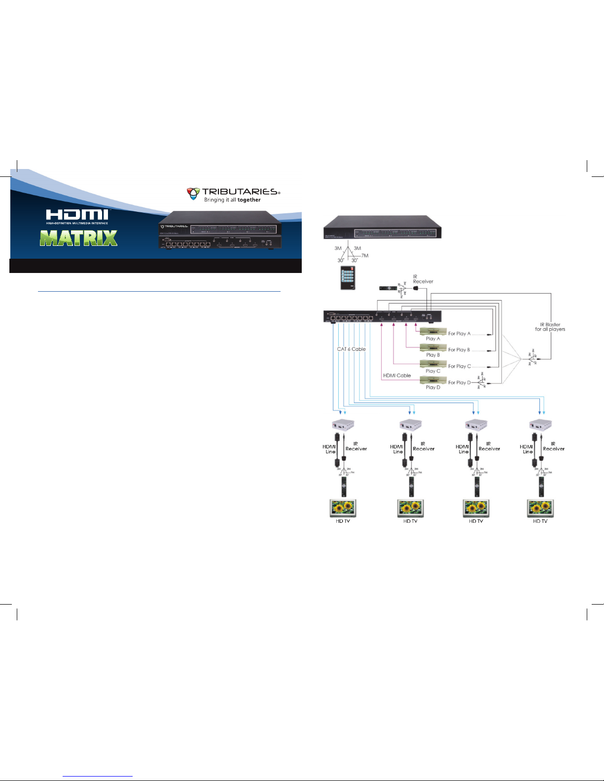
9. Connection & Installation ..................................................................... 6
10. Specifications ......................................................................... Back Cover
1
1. Introduction
Tributaries HM440IR 4X4 HDMI Matrix switch is a high performance system
that allows an IR signal to pass along with the HDMI signal over dual CAT6
cabling. The IR function provides for the control of remote source equipment.
It is compatible with HDMI v1.3 specifications, a cutting edge technology which
defines support for Deep Color (12 bits/color) video and new lossless compressed
(Dolby® TrueHD, Dolby Digital® Plus and DTS®-HD Master Audio) digital audio.
The HM440IR offers the maximum convenience in HDMI signal distribution. Each
of the four HDMI sources can be directed to any one of the four HDMI displays
allowing each display to simultaneously show a different source. The HDMI signal,
as it progresses through the system, is re-timed and level-compensated. The use
of CAT6 provides for a maximum distance of 148ft (45m) at 1080p/8-bit color. The
Tributaries HXC6R passive CAT6 repeater can be used to double the maximum
distance.
9. Connection and Installation
Page 3
2. Features
Extends 12 bit color 1080p HD up to 20 meters over dual CAT6•
Extends 8 bit color 1080p HD up to 45 meters over dual CAT6•
Supports IR signal transmission from a remote source to a display over same •
dual CAT6
Supports RS232 control and CEC bypass•
Supports new lossless compressed Digital Audio like Dolby•
®
TrueHD, Dolby
Digital® Plus and DTS®-HD Master Audio
HDMI input compensation, clock/phase adjustments and the elimination •
of jitter
Supports HDMI input and output cables up to 15 meters•
Compliant with HDMI 1.3 HDCP 1.1 and DVI 1.1 standards•
Supports xvYCC Color Space•
3. Package Contents
HM440IR HDMI 4X4 Matrix Switch with 5V/1A universal Power Supply•
Remote Control with Battery•
One IR receiver cable•
1 set of rack ears•
One HXC6IR-RX Receiver with 5V/1A universal Power Supply•
Five IR blaster cables•
Operation manual•
5
2
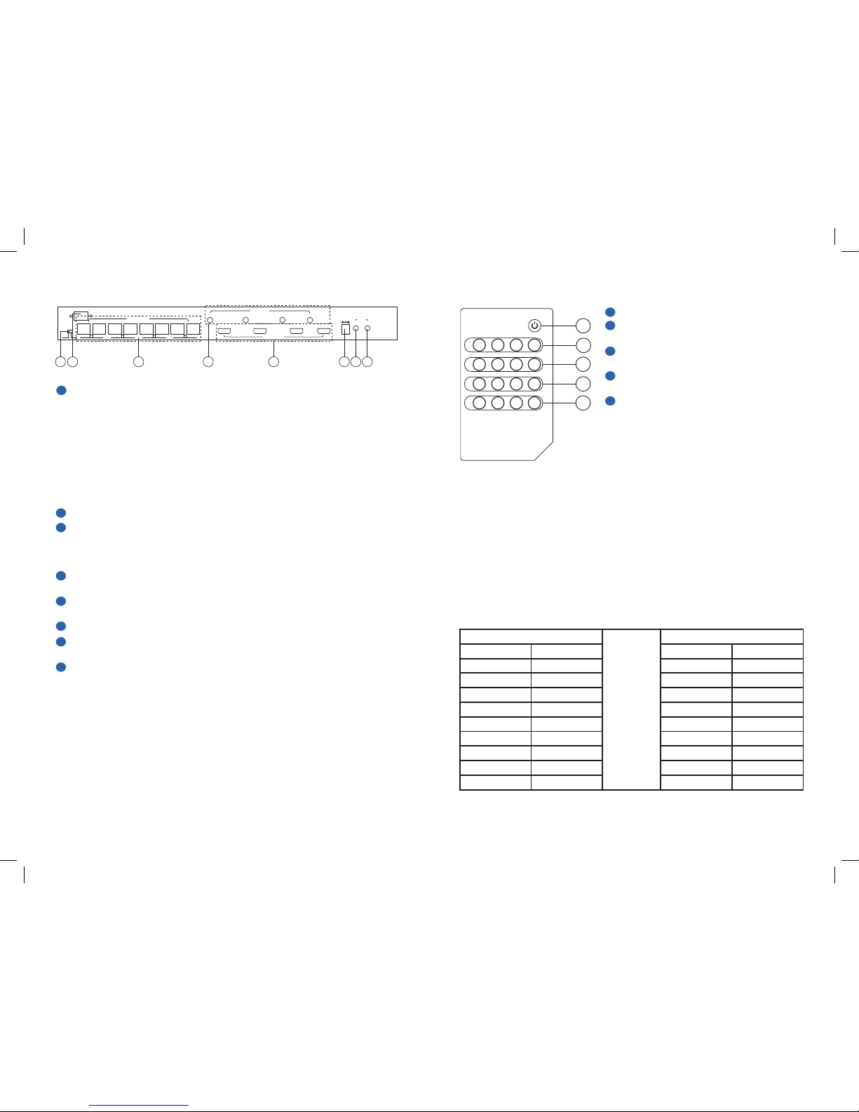
4. HM440IR Operation Controls and Functions
4.1 Front Panel
Remote Control Sensor
Power switch and indicator light: LED will illuminate when the power is on
Input selection A/B/C/D and indicator lights: Depress the HDMI OUT button to
switch to your desired source. The LED illuminates to indicate the input source
being routed to that output.
HDCP indicators: This LED will illuminate when the source chosen has HDCP
protection detected.
HDMI/DVI indicators: When the incoming signal is HDMI, this LED will
illuminate. When playing content from a DVI source, this LED will not light.
1
2
3
4
5
DDC
STD TV
VIDEO DDC VIDEO DDC VIDEO DDC VIDEO
4
4 3 2 1
3 2 1
HDMI INPUT
IR OUT
IN
DC 5V IR MAIN
OUT
CAT5 OUTPUT
2 3 4 5 6 7 81
11 1 1
POWER
IN
HDMI OUT
1
HDCP
HDMI/DVI
EDID
A
11 1 1
IN
HDMI OUT
1
HDCP
HDMI/DVIB11 1 1
IN
HDMI OUT
1
HDCP
HDMI/DVIC11 1 1
IN
HDMI OUT
1
HDCP
HDMI/DVI
D
CMLUX-4H4CAT
HDMI V1.3 to CAT6 4x4 Matrix
2 3 4 51
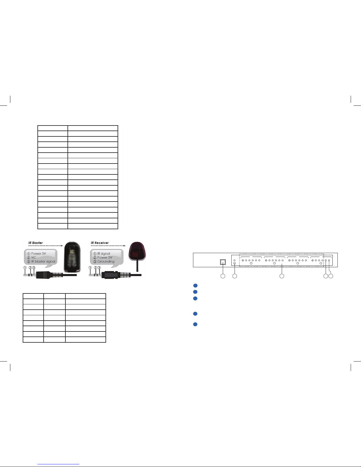
7. IR Cables
Command Action
Power 00 Power Off (standby)
Power 01 Power On
Port 11 Output A select Input 1
Port 12 Output A select Input 2
Port 13 Output A select Input 3
Port 14 Output A select Input 4
Port 21 Output B select Input 1
Port 22 Output B select Input 2
Port 23 Output B select Input 3
Port 24 Output B select Input 4
Port 31 Output C select Input 1
Port 32 Output C select Input 2
Port 33 Output C select Input 3
Port 34 Output C select Input 4
Port 41 Output D select Input 1
Port 42 Output D select Input 2
Port 43 Output D select Input 3
Port 44 Output D select Input 4
6.2 RS-232 Commands
8. RJ45 Pin Assignments
Pin Video DDC
1 TX2+ DDC Bus Clock
2 TX2- NC
3 TX1+ DDC Bus Data
4 TX0+ Power 5 volt
5 TX0- GND
6 TX1- IR IN
7 TXC+ HPD
8 TXC- NC
Page 4
4
3
4.2 Back Panel
EDID Control Switch: Default setting is TV, switch to STD to use built in EDID.
• WhenEDIDisswitchedtoTV,theunitwilldetecttherstHDMIoutput
source's EDID and record it in the unit. If the first detected output source is
DVI, it will skip onto the next source until an HDMI source is detected. The
detection priority is HDMI v1.3 > HDMI v1.2 > DVI.
• WhenEDIDisswitchedtoSTD,theunitwilluseitsbuilt-in
EDID that supports:
Video: 1080p 12-bit (max) supports xvYCC
Audio: PCM 2CH
• TheEDIDselectionwillonlybeactivatedaftertheunitisre-pluggedand
powered on.
RS-232: Connect a D-sub 9-pin cable to this port for controlling unit via RS-232.
VIDEO /DDC CAT6 Outputs: Connect the Video Input of the Receiver to the
Video output of the Transmitter using CAT6E/23AWG/solid cable. Connect the
DDC input of the Receiver to the DDC output of the Transmitter using CAT6
cable. CAT5 cable can be used for DDC only if available with the same result.
IR Out: Connect the IR blaster cables (included). Place blaster near each source
for IR signal sending
HDMI Inputs: Connect the HDMI cable from your source such as DVD player or
Set top box.
DC 5V Power: Connect the 5 volt power supply (included).
IR Main In: Connect the IR receiver cable (included). Allows signaling of source
equipment through existing remote controls.
IR Main Out: Connect the IR Blaster cable (included). Allows for IR signal to be
sent to the source equipment.
1
2
3
DDC
STD TV
VIDEO DDC VIDEO DDC VIDEO DDC VIDEO
4
4 3 2 1
3 2 1
HDMI INPUT
IR OUT
IN
DC 5V IR MAIN
OUT
CAT5 OUTPUT
2 3 4 5 6 7 81
EDID
4
5
6
7
8
5. Remote Control
HM440IR
Remote Control Console
Pin Definitions Pin Definitions
1 NC 1 NC
2 TxD 2 RxD
3 RxD 3 TxD
4 NC 4 NC
5 GND 5 GND
6 NC 6 NC
7 NC 7 NC
8 NC 8 NC
9 NC 9 NC
POWER
OUTPUT
1 2 3 4
A
OUTPUT
1 2 3 4
B
OUTPUT
1 2 3 4
C
OUTPUT
1 2 3 4
D
CR-33
2
3
4
5
1
Power: Depress to turn unit on or off
Output A: Depress 1, 2, 3 or 4 to select
desired input source for Output A.
Output B: Depress 1, 2, 3 or 4 to select
desired input source for Output B.
Output C: Depress 1, 2, 3 or 4 to select
desired input source for Output C.
Output D: Depress 1, 2, 3 or 4 to select
desired input source for Output D.
1
2
3
4
5
Baud Rate: 9600bps•
Data Bit: 8 bits•
Parity: None•
Stop Bit: 1 bit•
Flow Control: None•
6.1 RS-232 Pin Definitions
6. RS-232 Protocol
 Loading...