

Page 1
Page 2
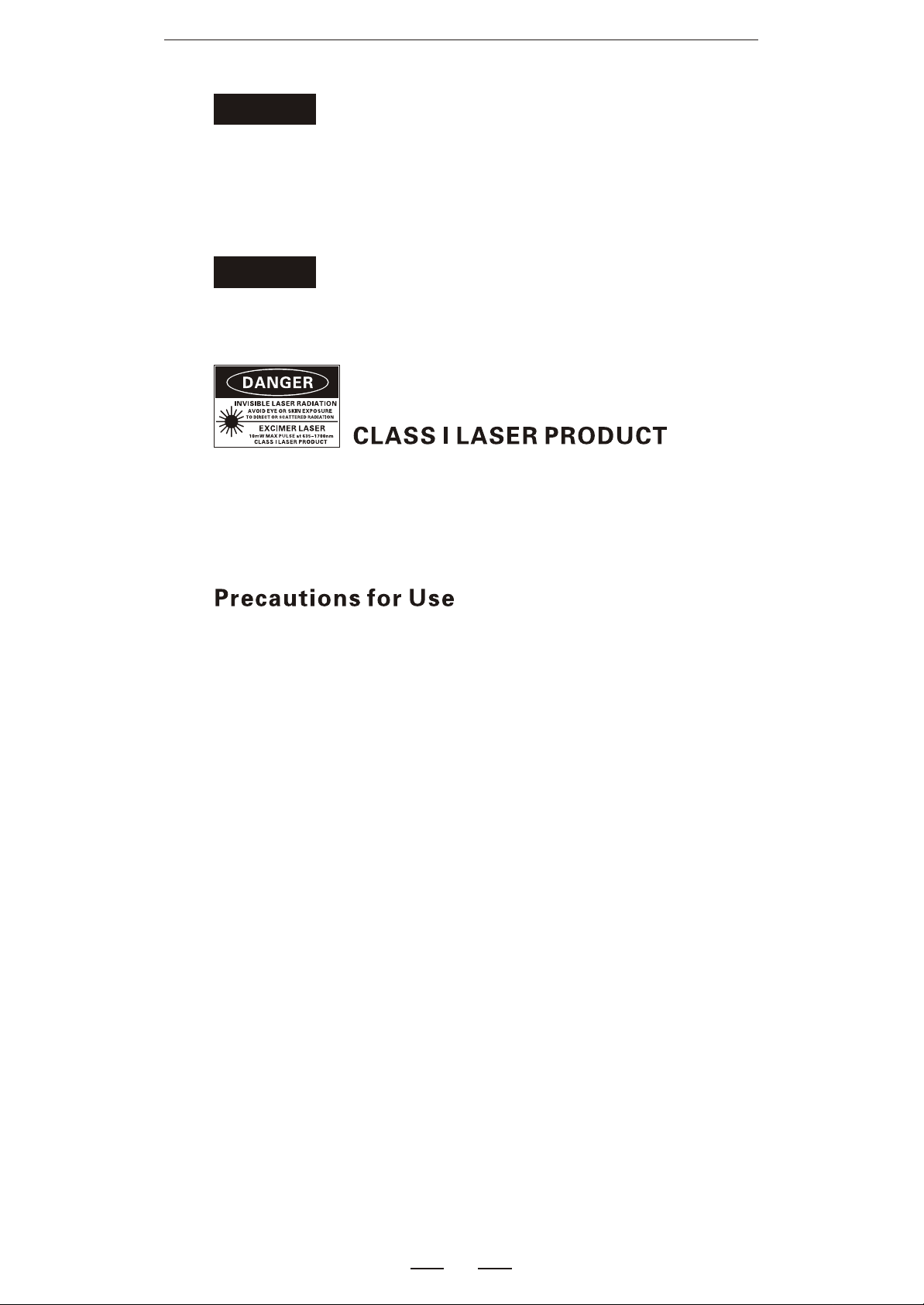
WARNINGWARNING
You are cautioned that changes or modifications not espressly approved in
this document could void yout authority to operate this equipment.
To reduce the risk of fire or electric shock,do not expose this apparatus to
rain or moisture.
To avoid electrical shock, do not open the cabinet. Refer servicing to qualified personnel only.
NOTENOTE
As the laser is harmful to the eyes, do not attempt to disassemble the cabinet.
Use batteries
At the same time, can not use different style or different capacitance batteries.
And only charge the rechargeable batteries.
Avoiding condensation problems
As much as possible, avoid sudden temperature changes. Do not attempt
to use the drive immediately after moving it from a cold to a warm location,
to raising the room temperature suddenly, as condensation may form with
in the drive. If the temperature changes suddenly while using the drive,
stop using it and take out batteries for at least an hour.
Storage
When long time no use,must take out the batteries to avoid destroying the
device.
1
Page 3
Standard
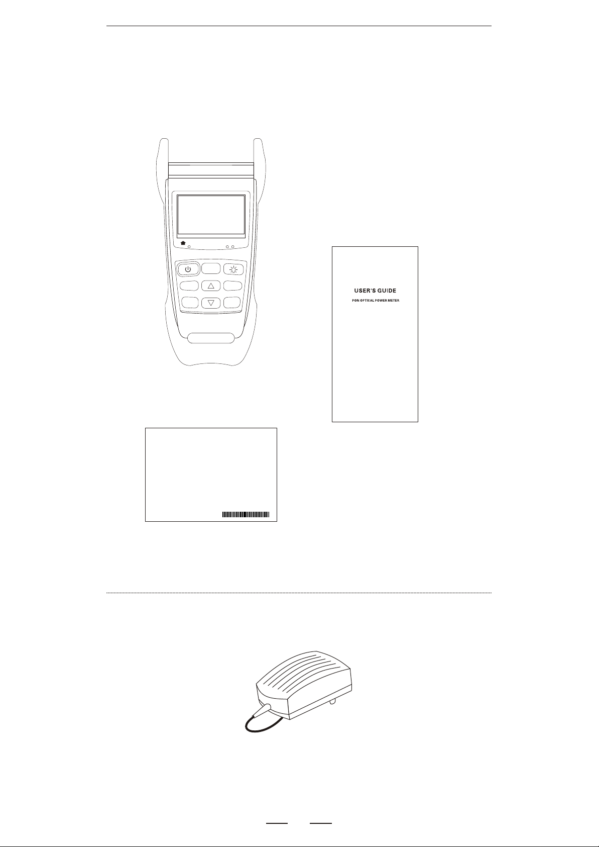
First check the accessories
()If any accessory is short please relate with the dealer ASAP
1310nm
ONT
>2S PERM
dBm/dB
Save
ReCall
CO
F/P
mode
Host
1490nm 1550nm
OLT Video
Threshold
REF/
Enter
Manual
Calibration Certificate
Optional
AC/DC Adaptor
2
Page 4
3
1
Description
19
2
16
1490nm 1550nm
CO
F/P
mode
OLT Video
Threshold
4
7
8
1310nm
ONT
>2S PERM
dBm/dB
10
13
Save
ReCall
REF/
Enter
14
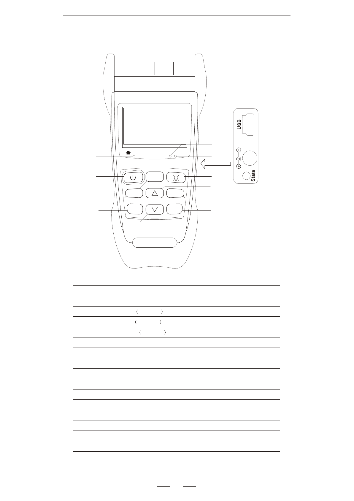
1- ONT (1310nm) input connector
2-OLT/Video (1490/1550nm) input connector
3-LCD
4-ONT warning LED 1310nm
5
6
9
11
12
15
9V1A9V
1A
17
18
5-OLT LED 1490nmwarning
6-Video LED 1550nmwarning
7-Power Key
8-F/P mode Key ( PASS, WRNG, FAIL)
9-Backlight Key
10-Unit Key ( dBm, dB )
1 1-Up Key
12-Threshold Key
13-Save Key
14-Down Key
15-REF Key / Enter Key
16-USB port
17-AC/DC port (Chargeable)
18-Battery charging LED
19- Connector of VFL or OPM
3
Page 5
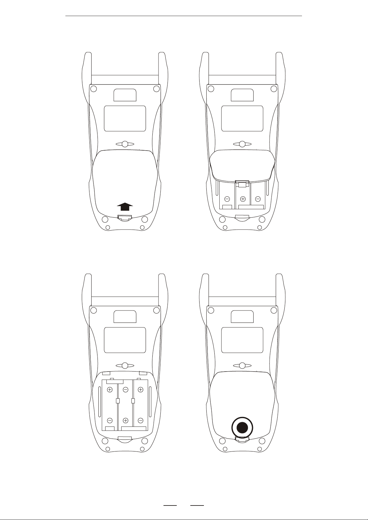
Set batteries
Warning:At the same time, can not use different style and different capacitance batteries.
1.Press and push down
2.Open the lid
3.Place the batteries
4.Close the lid and push up
4
Page 6
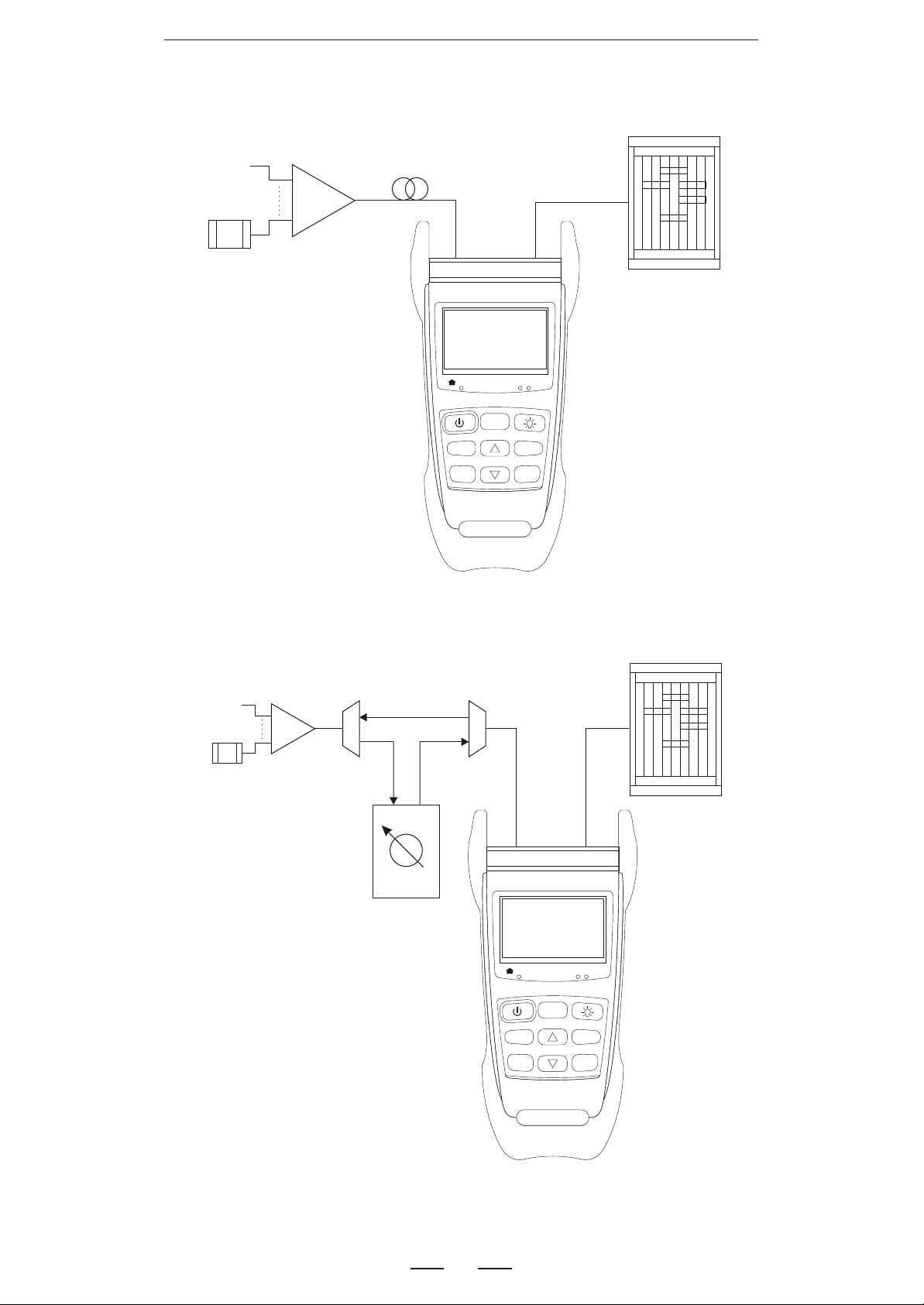
PON testing
ONT
Optical Splitter
Data Networks Analyser
IXIA/Smartbits
Fiber
mode
CO
F/P
1490nm 1550nm
OLT Video
Threshold
REF/
Enter
1310nm
ONT
>2S PERM
dBm/dB
Save
ReCall
OL T
Optical Splitter
Lamda
ONT
Demultiplexer
Data Networks Analyser
IXIA/Smartbits
1490nm
1310nm
Lamda
Multiplexer
Variable Optical
Attenuator
1310nm
ONT
>2S PERM
dBm/dB
Save
ReCall
mode
CO
F/P
1490nm 1550nm
OLT Video
Threshold
REF/
Enter
OLT
5
Page 7
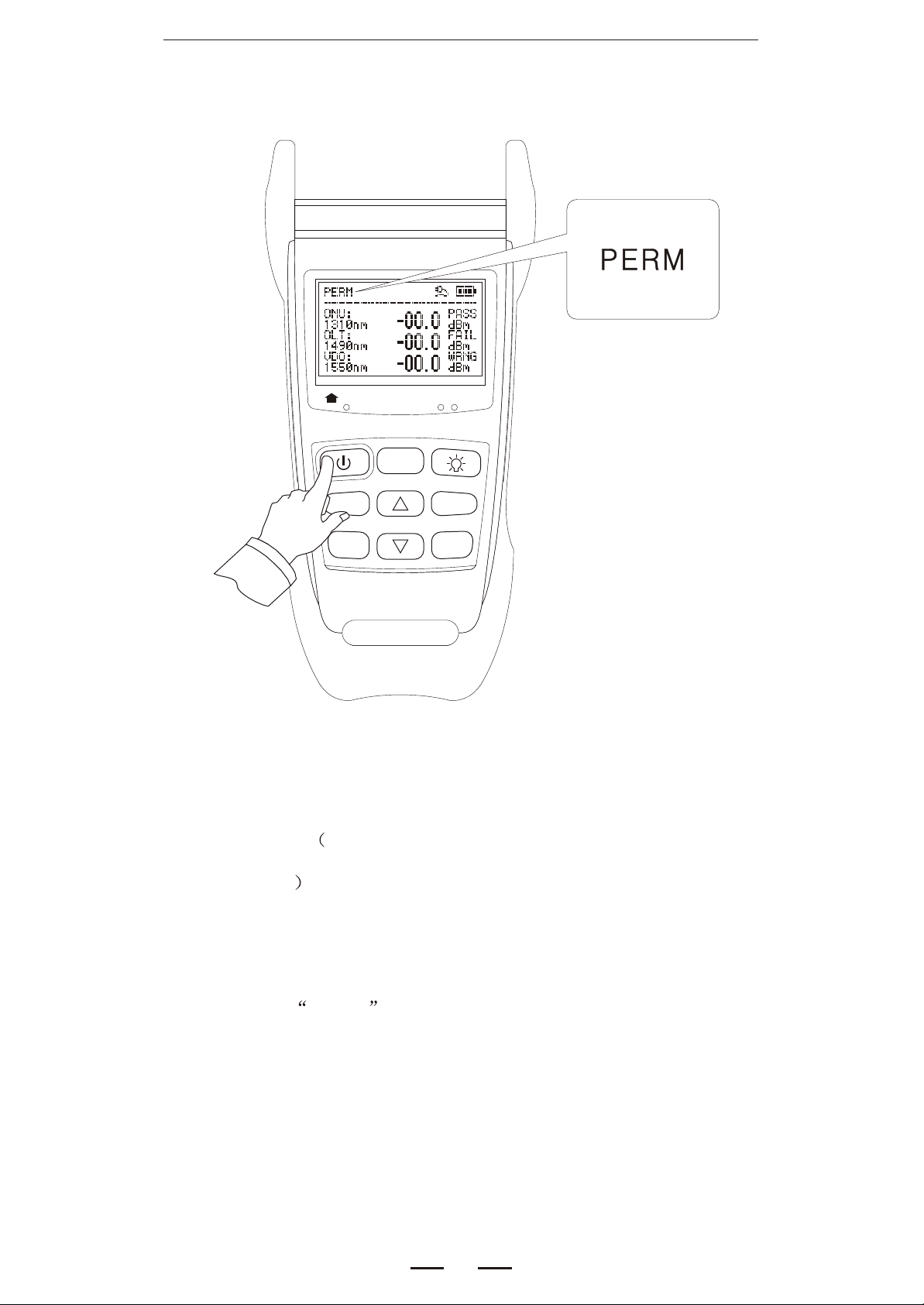
Power on/off, auto power off
1310nm
ONT
>2S PERM
dBm/dB
Save
ReCall
Press the Power key to turn on the device with auto
CO
F/P
mode
1490nm 1550nm
OLT Video
Threshold
REF/
Enter
power off. After 10 minutes no key pressed,it will auto
power off.
Press Power key for 2 seconds when turn on the
device, the auto power off will be cancelled,and the LCD
will show PERM .
Also press it to shut the device.
6
Page 8
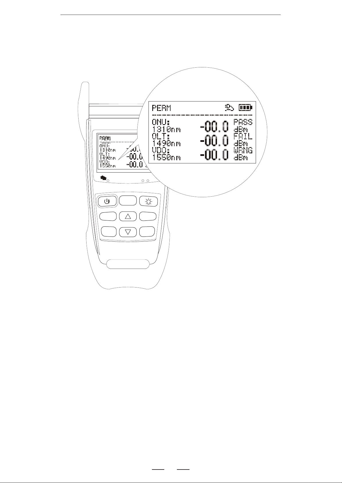
PON Test mode
1310nm
ONT
>2S PERM
dBm/dB
Save
ReCall
1490nm 1550nm
CO
F/P
mode
OLT Video
Threshold
REF/
Enter
It can test the signal of 1310,1490,1550nm and show its
power in the same time.
HI and LO mean the result is out of the test range
7
Page 9
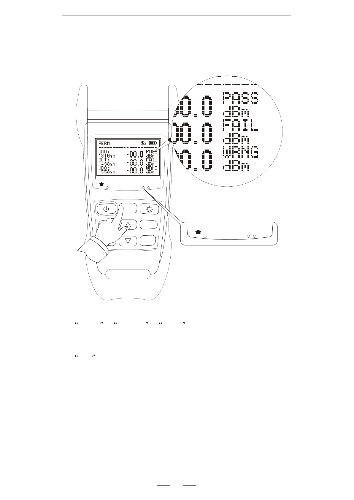
F/P Mode
1310nm
ONT
>2S PERM
dBm/dB
Save
ReCall
1490nm 1550nm
CO
F/P
mode
OLT Video
Threshold
REF/
Enter
1310nm
ONT
PASS , WRNG , FAIL :
alarm, depends on the threshold the user set
1490nm 1550nm
CO
OLT Video
F/P :
Open or close the alarm function ( PASS, WRNG, FAIL)
On LCD there are warning words beside the result
And the LED of each wavelength will turn on:
RED LED: FAIL
ORANGE LED: WRNG
GREEN LED: PASS
8
Page 10
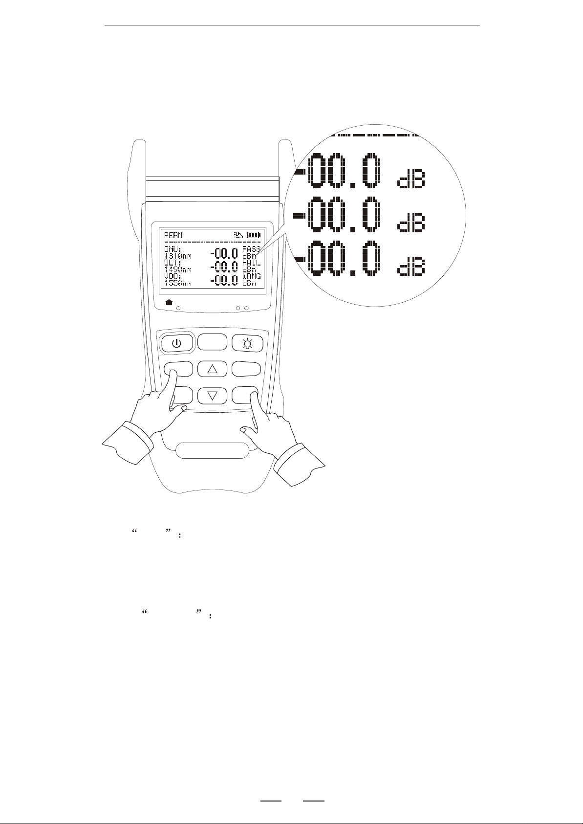
PON REF set
1310nm
ONT
>2S PERM
dBm/dB
Save
ReCall
1490nm 1550nm
CO
F/P
mode
OLT Video
Threshold
REF/
Enter
REF It will show you the reference value you stored
before, then turn the unit to dB.Keep pressing for 2 seconds,
you can save current value as reference.
dBm/dB Change the unit ( dBm, dB)
Note: The value must be in the testing range when you press
these two keys.
9
Page 11
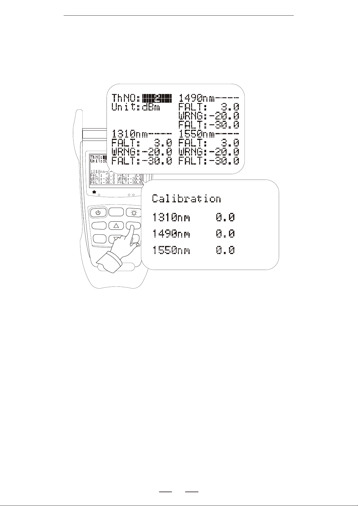
Threshold & Calibration
F/P
mode
CO
1490nm 1550nm
OLT Video
Threshold
REF/
Enter
1310nm
ONT
>2S PERM
dBm/dB
Save
ReCall
Press the "Threshold " key you can shift the interface.
The picture show the threshold set interface.
User can set these 10 threshold. Please see page 11
for details.
10
Page 12
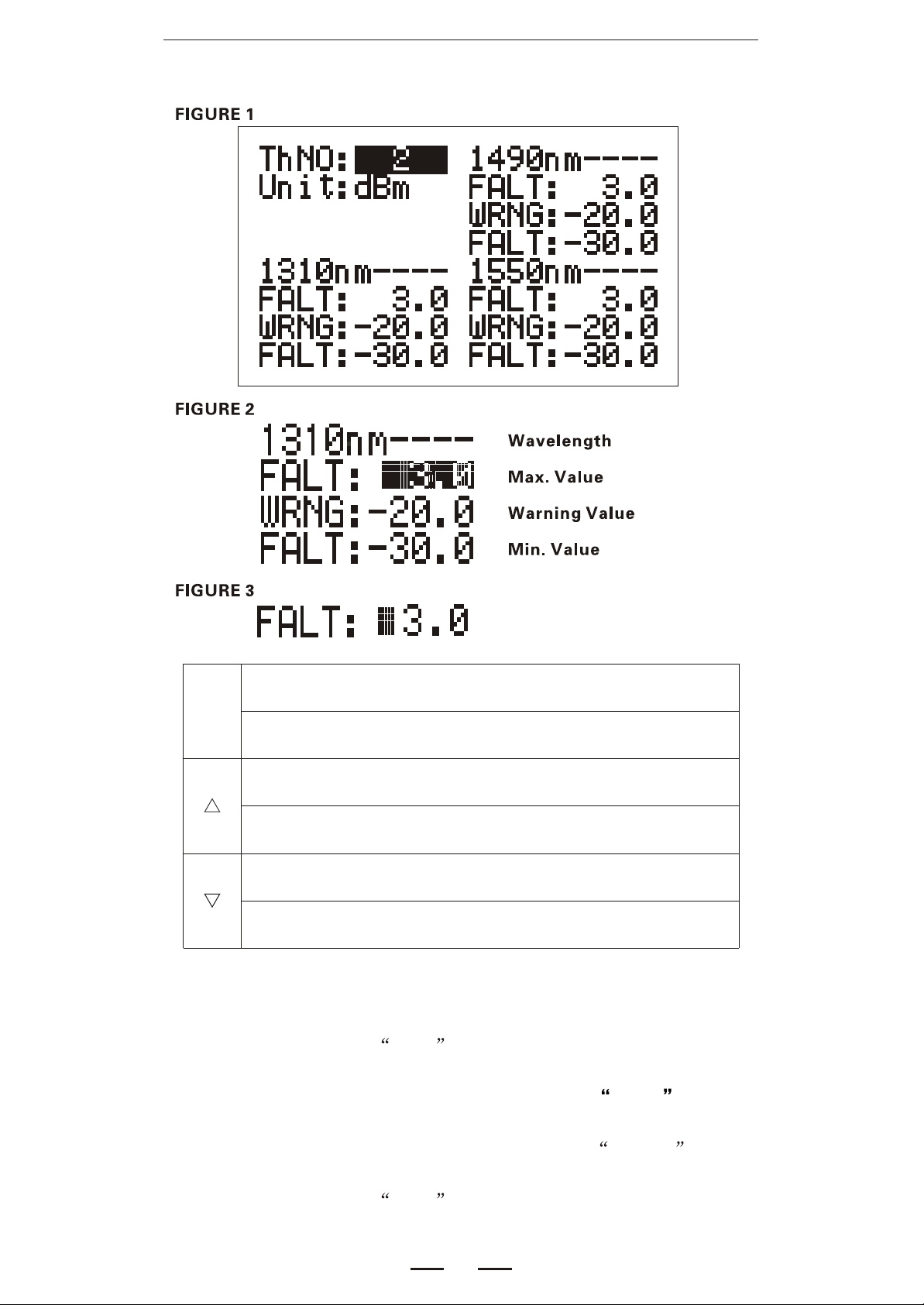
Threshold & Calibration
When the cursor is on "ThNo:" you can change the
Enter
threshold number, (see figure 1)
When the cursor is on "FALT:""WRNG""FALT:"you can
shift the cursor from each bit of the data. (see figure 2)
Move the cursor up, please note the cursor is not in one
bit of any data
Increase the bit by 1, when the cursor is in one bit of any
data (see figure 3)
Move the cursor down, please note the cursor is not in one
bit of any data
Decrease the bit by 1, when the cursor is in one bit of any
data (see figure 3)
How to understand the threshold:
1.Each wavelength has its threshold.
2.If the current value > Max. Value, the alarm of corresponding
wavelength will be FAIL .
3.If the current value < Max. Value, but > Warning Value, the
alarm of corresponding wavelength will be PASS
4.If the current value < Warning Value, but > Min. Value, the
alarm of corresponding wavelength will be WRNG
5.If the current value < Min. Value, the alarm of corresponding
wavelength will be FAIL .
11
Page 13
Threshold & Calibration
F/P
mode
CO
1490nm 1550nm
OLT Video
Threshold
REF/
Enter
1310nm
ONT
>2S PERM
dBm/dB
Save
ReCall
The followings will cause the test result differenct:
1.Different standard
2.Not standard accessories.(Lab level 0 dB adapter, 0 dB
patch cord)
3.Dirty of connector
4.More than 1 year no calibration
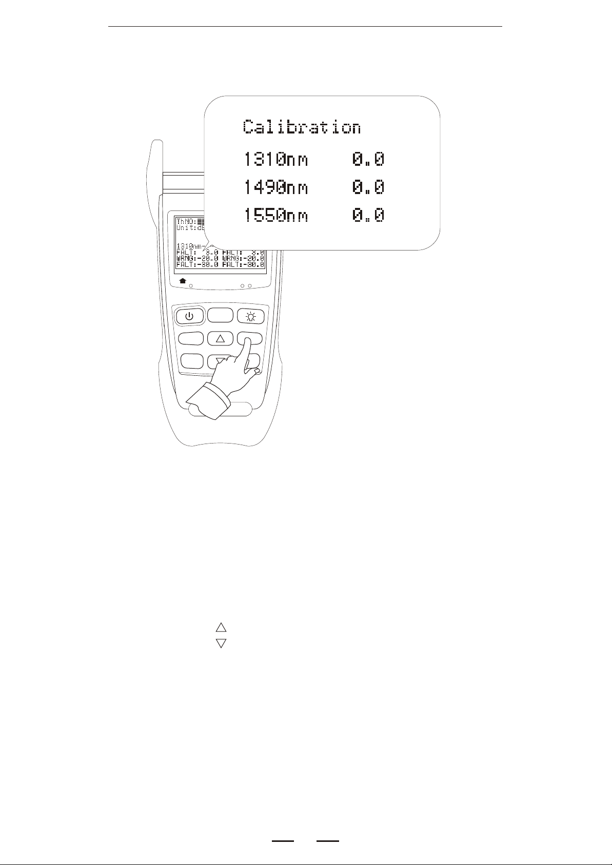
User can do easy calibration as the following steps:
Press the "TH" key to the calibration menu as the picture.
1.Press the "SEL" key to move the cursor.
2.Press the " " key to increase the value
3.Press the " " key to decrease the value
4.Press again the "TH" key to save and exit.
Please note the adjustable range of each wavelength is
from -5.0 to +5.0, if the difference is out of the range, we
suggest user send back to manufacturer to do completely
calibration.
.
12
Page 14
Data Storage
1310nm
ONT
>2S PERM
dBm/dB
Save
ReCall
1490nm 1550nm
CO
F/P
mode
OLT Video
Threshold
REF/
Enter
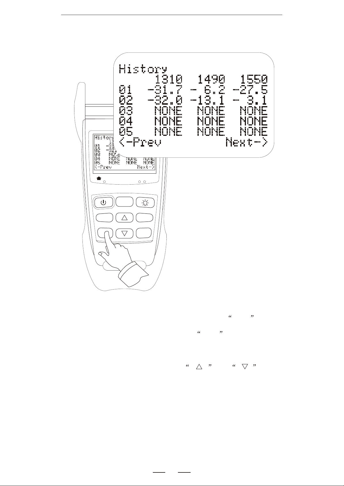
When in testing interface, user can press Save key
to save current value. And press the Save key for 2
seconds to the History interface.
In the History interface, press
to change the history page.
13
and key
Page 15
VFL Mode
OPTIONAL
1310nm
ONT
>2S PERM
dBm/dB
Save
ReCall
1490nm 1550nm
CO
F/P
mode
OLT Video
Threshold
REF/
Enter
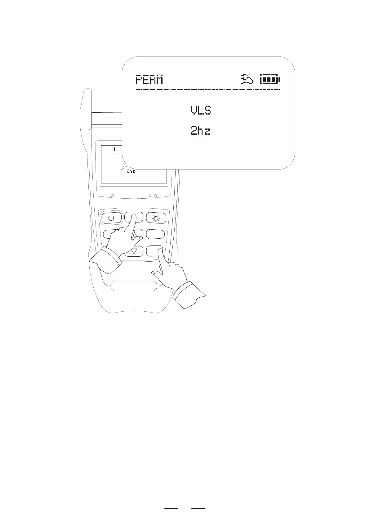
In the PON test interface, press F/P mode Key for 2
seconds, it will turn to the visual fault locator mode, press
again to return to the PON test interface.
In visual fault locator mode:
Threshold: change the light from continuous to 2Hz flash.
14
Page 16
OPM Mode
OPTIONAL
1310nm
ONT
>2S PERM
dBm/dB
Save
ReCall
1490nm 1550nm
CO
F/P
mode
OLT Video
Threshold
REF/
Enter
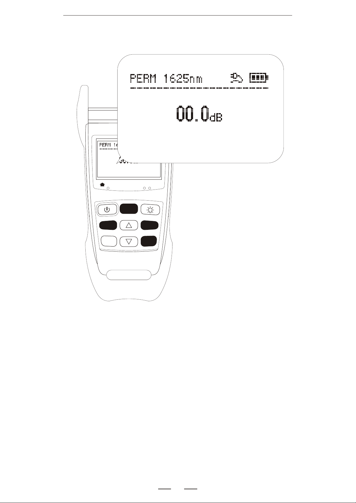
In the PON test interface, press F/P mode Key for 2
seconds, it will turn to the normal optical power meter
mode, press again to return to the PON test interface.
In normal power meter mode:
dBm/dB: change the unit, dBm, uW and dB
Threshold: change the wavelength,
850/1300/1310/1490/1550/1625
REF/Enter: press to check the REF value
press for 2 seconds to save the current value
as a new REF value
15
Page 17
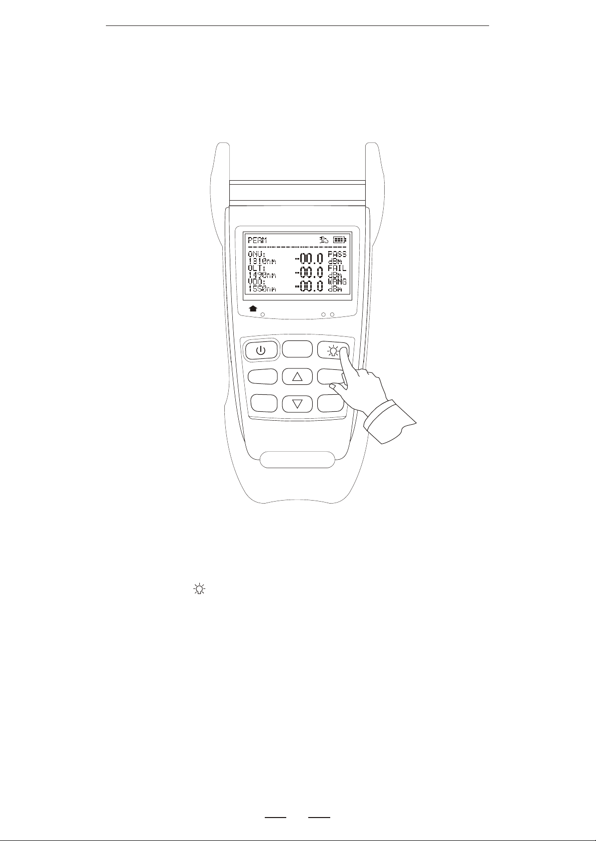
Backlight
1310nm
ONT
>2S PERM
dBm/dB
Save
ReCall
CO
F/P
mode
1490nm 1550nm
OLT Video
Threshold
REF/
Enter
Turn on or turn off the backlight
16
Page 18
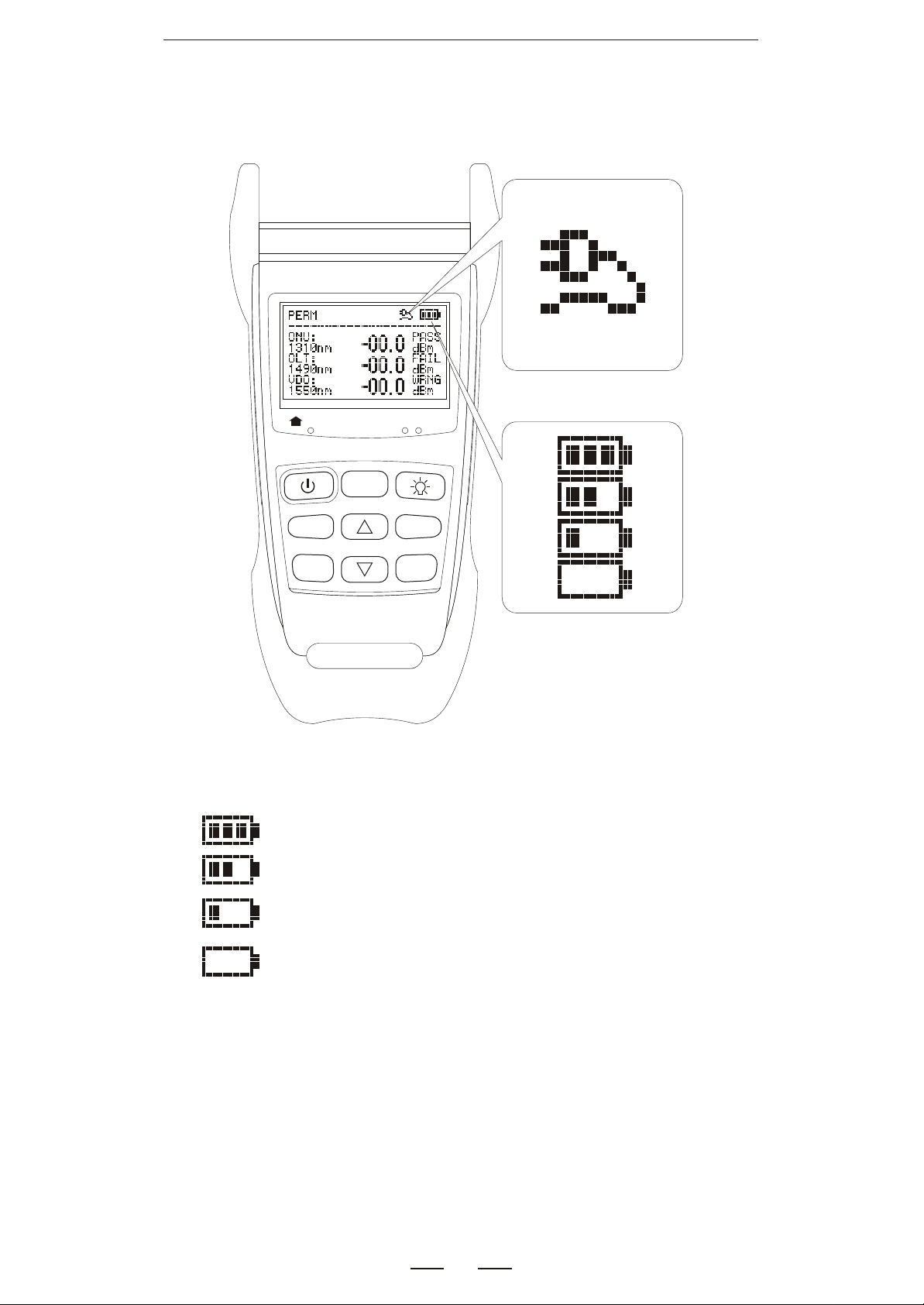
Battery energy detect
1310nm
ONT
>2S PERM
dBm/dB
Save
ReCall
1490nm 1550nm
CO
F/P
mode
OLT Video
Threshold
REF/
Enter
Remain80%---100%
Remain40%---80%
Remain20%---40%
Remain less than20%
If the energy is too low, the beep will be on and device
will auto power off.
17
Page 19

Battery charge
First you must use the rechargeable batteries. When the
energy is less than 20%, you should charge the batteries.
Long time low energy, the life of the batteries will be short.
When charging, the battery indication on LCD will flash.
After charging fully, the indication will stop flashing and show
full. Don't charge for more than 24 hours. If charging while
using the device, the time will be longer. The rechargeable
batteries must be in device when you use the AC/DC adaptor
for charging. And do not charge the non-rechargeable
batteries, or the device will be destroyed and also lose the
guarantee.
18
Page 20

Maintenance and calibration
Routine attention
1.Fiber-optical adapter should keep clean.
2.Please store the device in dry and ventilated place.
3.The long period no use , please take out the batteries.
Common malfunction
DescribedDescribed
Can not turn on
After turn on shut it
immediately
Can not charge
Display the messy
code
Operation do not
have reaction
Malfunction causeMalfunction cause
No battery
Check battery capacities
Use Non-rechargeable
batteries
Reset is incorrect
Program is disorderly
Handle wayHandle way
Check battery setting
Change battery
Change battery
Reset
Reset
19
Page 21
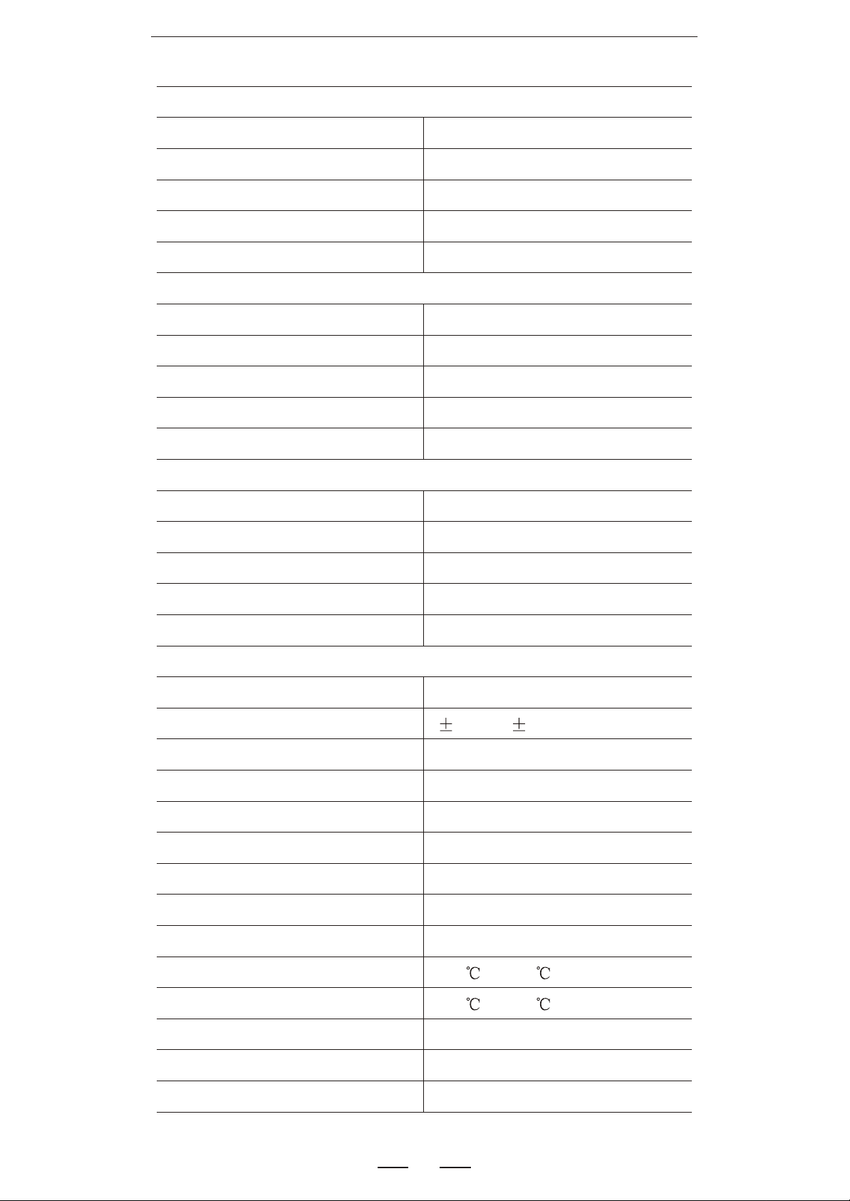
PON Detailed Parameter
Measurement of 1310nm
Pass band
Measurement range
Max. permitted input level
Isolation of 1490/1550nm
Accurate Of Burst Signal
Measurement of 1490nm
Pass band
Measurement range
Max. permitted input level
Isolation of 1310nm
Isolation of 1550nm
Measurement of 1550nm
Pass band
Measurement range
1260nm~1360nm
+10dBm~-35dBm
+15dBm
>40dB
+/-0.5dB
1480nm~1500nm
+10dBm~-50dBm
+15dBm
>40dB
>40dB
1530nm~1570nm
+25dBm~-45dBm
Max. permitted input level
Isolation of 1310nm
Isolation of 1490nm
Optic connector
Accurate
Linearity
Pass through insertion loss
Threshold sets
Data memory
Extension interface
Power supply
Battery life
Operation Temp.
+25dBm
>40dB
>40dB
SC/PC or customized
0.2dB/ 0.5dB(burst mode)
0.1dB
<1.5dB
Yes
Yes
USB
AA x 3 or AC/DC adapter
>20H
-10 ~+60
Storage Temp.
Relative humidity
Size
Weight
-20 ~+70
<95%(non-condensing)
190mm*95mm*50mm
400g
20
Page 22
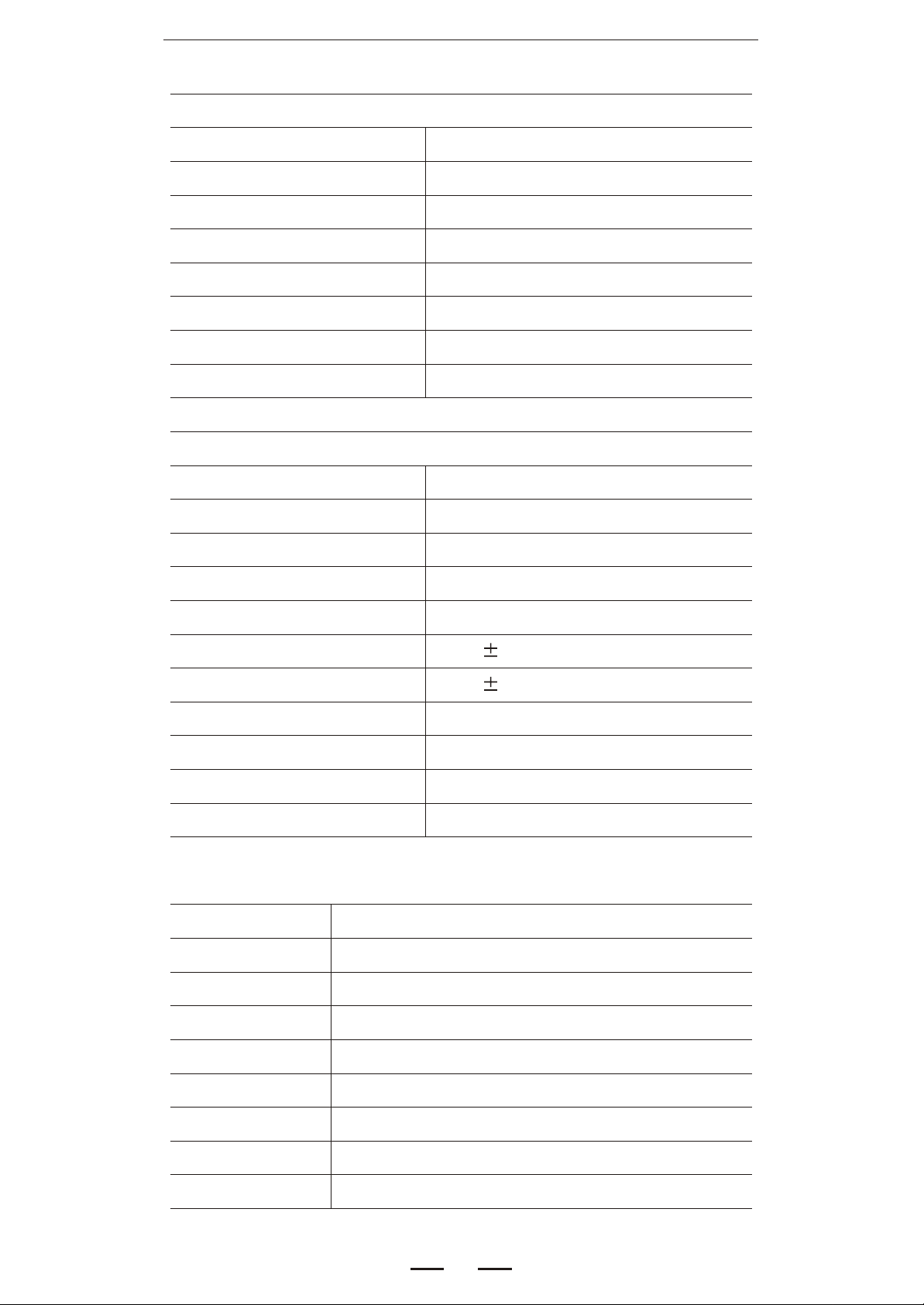
OPM/ VFL Detailed Parameter
Visual Fault Locator
Wavelength
Output Power
Option 1
Option 2
Option 3
Option 4
Option 5
Option 5Option 5
Connector
Optical Power Meter
Measurement range
Option 1
Option 2
Option 3
650nm
1mW
10mW
15mW
20mW
25mW
2.5mmUPP
-70dBm~+8dBm
-60dBm~+18dBm
-50dBm~+26dBm
Resolution
Accurate
Linearity
Detector
Connector
Range of Wavelength
Calibrated Wavelength
Model Option
Option 1
Option 2
Option 3
Option 4
Option 5
PON Power Meter
PON Power Meter + 1mW VFL
PON Power Meter + 10mW VFL
PON Power Meter + 15mW VFL
PON Power Meter + 20mW VFL
0.01dB
0.2dB
2%
InGaAs
FC/PC & 2.5mm UPP
700~1700nm
850/1300/1310/1490/1550/1625nm
Option 6
Option 7
Option8
Option 9
PON Power Meter + 25mW VFL
PON Power Meter + OPM(-60~+18dBm)
PON Power Meter + OPM (-60~+18dBm)
PON Power Meter + OPM (-50~+26dBm)
21
 Loading...