

Page 1
Model Item no.
GNS 20 339120
GNS 30 339130
Version
DE - EN
triax.com
GNS 20 - GNS 30
Betriebsanleitung - Operating instructions
Terr. Mehrbereich Verstärker
Terr. Multiband Amplifier
Page 2

Recyclinghinweis
Dieses Produkt ist nach seiner Ver wendung entsprechend den aktuellen Entsor gungs vorschriften Ihres Landkreises/
Landes/Staates als Elektronikschrott einer
geord neten Entsorgung zuzuführen.
ACHTUNG: Die Sicherheitsanforderungen
nach EN 50083-1 sind unbedingt
zu beachten.
3
Potentialausgleich, Erdung, Schutzleiter:
Für die gesamte Anlage ist ein Potentialaus gleich mittels eines mechanisch stabilen
Schutzleiters mit einem Querschnitt von min. 4
mm2 herzustellen. Eine Anschluss mög lich keit
besteht an der Potential aus gleichs schrau be
an der rechten Wandhalterung.
HINWEIS:
Das Gerät darf keinem Tropf- oder
Spritzwasser ausgesetzt werden.
Sicherheitsanforderungen
Montage
3
Montageort und Einbaulage so wählen, daß
die Konvektionskühlung des Verstärkers nicht
behindert wird:
- Montage waagrecht (senkrechte Ausrichtung
der Kühlrippen, siehe Abb. 1)
- frei an der Wand
- Einbau in einen Schrank nur bei Beachtung
der zulässigen Betriebs-Umgebungstemperatur (gemessen am Luftstrom unter
dem Verstärker)
3
Wandbefestigung
- an den Halterungen mit passenden
Schrauben (ø max. 4.8 mm)
- Abstand der Befestigungen 158 mm
Copyright © Triax
Jegliche Arten von Kopien und Verfielfältigungen nur nach Genehmigung des Urhebers
Dieses Produkt darf nur gemäß dieser Anleitung
betrieben werden. Jede andere sachwidrige
Verwendung führt zum Erlöschen des
Garantieanspruchs.
Bestimmungsgemäße und sachwidrige Verwendung
2
Page 3
Die Multibandverstärker GNS verfügen über folgen de Einstellmöglichkeiten:
Vorein-
stellung
Pegelsteller
an allen Eingängen 0...-20 dB 0 dB
Spannungsversorgung
für die angeschlossenen
terrestrischen Antennen
Eingang UHF 0 / +5 V 0 V
Eingang VHFIII 0 / +5 V 0 V
Zusammenlegen der Eingänge UHF und VHFIII,
z. B. bei Verwendung
von Kombi-Antennen off/on off
Option:
Spannungsversorgung
der zusammengelegten
Eingänge UHF + VHFIII
(mit zusätzlichem Jumper,
nicht beiliegend) 0 / +5V -
Einstellungen werden wie folgt vorgenommen:
1. Abnehmen des Gehäusedeckels (Abb. 1):
Nach Lösen der Zentralschraube (a) wird der
Deckel anhand der kleinen Halterung links (b)
nach vorne abgenom men.
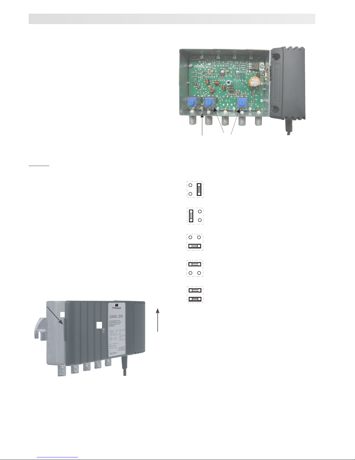
Nun sind Pegelsteller und Jumper auf der
Leiterplatte für Einstellungen zu gänglich.
Abb. 1: Gehäuse
Abb. 2: Einstellelemente
- Pegelsteller 0...-20 dB an jedem Eingang
- Stellung des Jumpers:
2. Einstellungen vornehmen:
3. Gehäusedeckel schließen:
Den Gehäusedeckel passend auf das Gehäuse
aufsetzen und ringsum andrücken, so dass die
Blechlamellen im geschlossenen Zustand von
innen gegen das Gehäuse gepresst werden.
Zentral schraube einschrauben.
Einstellmöglichkeiten
a
b
oben
keine Spannungsversorgung
für terr. Antenne
(Auslieferzustand)
+5V-Versorgung
an UHF
+5V-Versorgung
an VHFIII
keine Spannungsversorgung,
UHF + VHFIII gemeinsam an UHF-Eingang
+5V-Versorgung,
UHF + VHFIII gemeinsam an UHF-Eingang
Pegelsteller an allen
Eingängen
Jumper
3
Page 4

Technische Daten
Typ GNS 20 GNS 30
Best.-Nr. 339120 339130
Frequenzbereich
Eingang 1 - UHF 1 MHz 470...862 470...862
Eingang 2 - VHF III MHz 174...230 174...230
Eingang 3 - VHF I MHz - 47...68
- UHF 2 MHz - -
Eingang 4 - FM MHz 47...68 und -
- VHF I MHz 87,5...108 87,5...108
Option: Eingang 1 und Eingang 2
mit Jumper verbunden MHz 470...862 und 470...862 und
174...230 174...230
Verstärkung *
Eingang 1 - UHF (1) dB 22 31
Eingang 2 - VHF III dB 20 30
Eingang 3 - VHF I dB - 30
- UHF (2) dB - -
Eingang 4 - FM / VHF I dB 20 30
Pegelsteller
an allen Eingängen dB 0...-20 0...-20
Rauschmaß *
Eingang 1 - UHF (1) dB 4 4
Eingang 2 - VHF III dB 4 4
Eingang 3 - VHF I dB - 4
- UHF (2) dB - -
Eingang 4 - FM / VHF I dB 4 4
Ausgangspegel, IMA = 60 dB *
IMA 3 gem. EN 50083-5 dBµV 113 115
IMA 2 gem. EN 50083-5 dBµV 102 105
Elektrische Anschlusswerte
Versorgungsspannung (50 - 60 Hz) V~ 230 ±10% 230 ±10%
Leistungsaufnahme W 3,5 6
Umgebungsbedingungen gem. EN 60065
Betriebstemperaturbereich °C –25 … +55 –25 … +55
Schutzart II, schutzisoliert II, schutzisoliert
Schutzklasse IP 20 IP 20
MTBF (Belcore 25°C) h 300.000 300.000
Gehäuse
Gewicht kg ca. 0.68 ca. 0.68
Abmessungen B x H x T mm 150 x 80 x 50 150 x 80 x 50
HF-Anschlüsse 75 O F-Buchsen F-Buchsen
Schirmdämpfung
gem. EN 50083-2 Klasse A Klasse A
* Pegelsteller 0 dB
Triax GmbH
Karl-Benz-Str. 10
72124 Pliezhausen
Tel. +49 (0) 900 100 15 55 (49 Cent/Min.)
E-Mail: service_de@triax-gmbh.de
www.triax-gmbh.de
4
Page 5

Operating Instructions
Terrestrial Multiband amplifier
or common using the integrated jumper - e.g.
when using combination antennas.
3
Connectable +5 V remote supply to the UHF
or VHF III inputs - e.g. for supplying power to
active DVB-T antennas.
3
Level controller 0...-20 dB at each input
3
Low power consumption
3
Low-noise inputs for DVB-T
3
The die-cast housing with cooling fins reduces
the component temperature and thereby
increases both service life and reliability
3
HF connections: F sockets, molded
3
Conforms to the standards EN 60065,
EN 50083-3, EN 50083-5,
Description
GNS 20, 30 are low-noise multi-range
amplifiers with digital capability, four highly
selective range inputs and one output. For use
in all small and medium-sized common antenna
networks in which terrestrial signals must be
amplified.
High amplification and a high output level make
the GNS range of amplifiers suitable for both
DVB-T and analog antenna signals.
3
You can operate VHF III and UHF alternately
GNS 20
Order No.
339120
GNS 30
Order No.
339130
UHF VHF III - VHF I Out- GNS 20
/FM
put
UHF VHF III VHF I FM Out- GNS 30
put
5
896611-02-0112 All rights reserved. Subject to printing errors, mistakes and changes
Page 6

6
Safety Requirements
CAUTION: Observe the safety requirements
of EN 50083 -1
3
Equipotential bonding
The complete system must be provided
with equipotential bonding by means of a
mechanically stable protective conductor with
a minimum cross-section of 4 mm2. There is a
connection point at the earthing screw at the
right wall bracket.
NOTE:
The unit must not be exposed to
dripping or splashing water.
Installation
3
Choose a location and orientation that will not
impair the convection cooling of the amplifier:
•
Horizontal (cooling fins aligned vertically)
•
Uncovered on wall
•
Installed in a cabinet only in strict
conformance to the permissible ambient
operating temperature (measured in the air
stream underneath the amplifier)
3
Wall mounting
•
Fixed to brackets by appropriately sized
screws (dia. max. 4.8 mm)
•
Fixings 158 mm apart
When this product has reached the end
of its useful life, it is to be turned in for
proper disposal as electronic refuse in
compliance with the current disposal
regulations of your respective city/
country/state.
Recycling Information
This unit may only be operated as described in
these instructions. Any other form of incorrect
use shall result in all warranty claims being void.
Correct and incorrect use
Copyright © Triax A/S
Copies and reproduction is allowed only with the copyright holder‘s approval
Page 7

7
The Multiband amplifiers GNS have the following
setting possibilities:
Default
setting
Level adjuster,
at all inputs 0...20 dB 0 dB
Power supply for the
connected terrestrial
antennas
input UHF 0 / +5 V 0 V
input VHFIII 0 / +5 V 0 V
Combining the inputs
UHF and VHFIII, e.g.
when using combination
antennas off/on off
Option:
Power supply for the
combined inputs UHF
+ VHFIII (with additional
jumper, not included) 0 / +5V -
Settings are done as follows:
1. Remove the housing lid:
After slackening the central bolt (a) lift the lid
off by releasing the catch on the left-hand
side (b).
For adjustments now the level adjusters and
the jumper on the circuit board are accessible.
Fig. 1 Housing
Fig. 2 Adjuster elements
- Level adjuster 0...-20 dB at all inputs
- Position of the jumper:
2. Adjuster elements
3. close the housing lid:
Put the housing lid on the housing and press
all the way round. The sheet steel segments
will now be pressed against the inner wall of
the housing. Screw in the central screw.
Setting possibilities
a
b
above
Level adjusters at all
inputs
Jumper
no power supply
for terrestrial antenna
(Default setting)
+5V power supply
at UHF
+5V power supply
at VHFIII
no power supply
UHF + VHFIII common at input UHF
UHF + VHFIII common at input UHF
+5V power supply
Page 8

Copyright © 2016 TRIAX. All rights reserved. The TRIAX Logo and TRIAX, TRIAX Multimedia
are registered trademarks or trademarks of the TRIAX Company or its afliates.
All specications in this guide are subject to change without further notice.
TRIAX A/S | Bjørnkærvej 3 | DK-8783 Hornsyld | Denmark
triax.com/support
Technical Data
Type GNS 20 GNS 30
Order No. 339120 339130
Frequency range
Input 1 - UHF (1) MHz 470...862 470...862
Input 2 - VHF III MHz 174...230 174...230
Input 3 - VHF I MHz - 47...68
- UHF (2) MHz - -
Input 4 - FM MHz 47...68 and -
- VHF I MHz 87,5...108 87,5...108
option: input 1 and input 2
combined with jumper MHz 470...862 and 470...862 and
174...230 174...230
Gain *
Input 1 - UHF (1) dB 22 31
Input 2 - VHF III dB 20 30
Input 3 - VHF I dB - 30
- UHF (2) dB - -
Input 4 - FM / VHF I dB 20 30
Level controller
at all inputs dB 0...-20 0...-20
Noise figure *
Input 1 - UHF (1) dB 4 4
Input 2 - VHF III dB 4 4
Input 3 - VHF I dB - 4
- UHF (2) dB - -
Input 4 - FM / VHF I dB 4 4
Output level, IMR = 60 dB *
IMR 3 acc. EN 50083-5 dBµV 113 115
IMR 2 acc. EN 50083-3 dBµV 102 105
Power supply
Supply voltage (50 - 60 Hz) V~ 230 ±10% 230 ±10%
Power consumption W 3,5 6
Ambient conditions acc. EN 60065
Operating temperatur range °C –25 … +55 –25 … +55
Degree of protection II, isolated guard II, isolated guard
Protection class IP 20 IP 20
MTBF (Belcore @ 25°C) h 300.000 300.000
Housing
Weight kg ca. 0.68 ca. 0.68
Dimensions W x H x D mm 150 x 80 x 50 150 x 80 x 50
HF connections 75 O F connectors F connectors
Screening
acc. EN 50083-2 class A class A
 Loading...