

Page 1
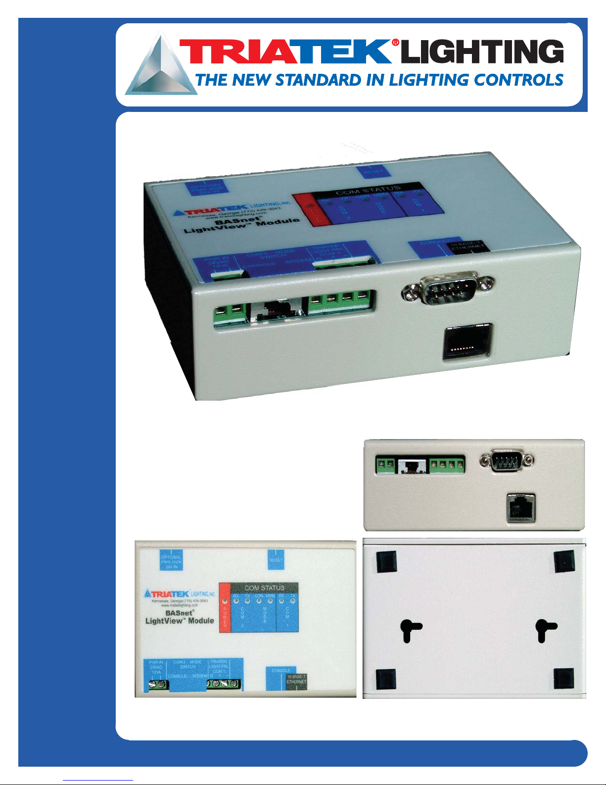
BASnet LightiView™ User’s Guide
1025 Cobb Place Blvd Suite 100 Kennesaw, GA 30144 • 800-241-9173 • www.triateklighting.com
Page 2
BASnet LightView User’s Guide
ATTENTION
This section serves as a notice of the immediate or potential dangers involved when
working with the equipment described throughout this manual. Any person involved
in installation, maintenance, or service of the equipment should first carefully
examine the equipment and read the instructions contained in this manual to ensure
that personal and/or equipment injury is avoided.
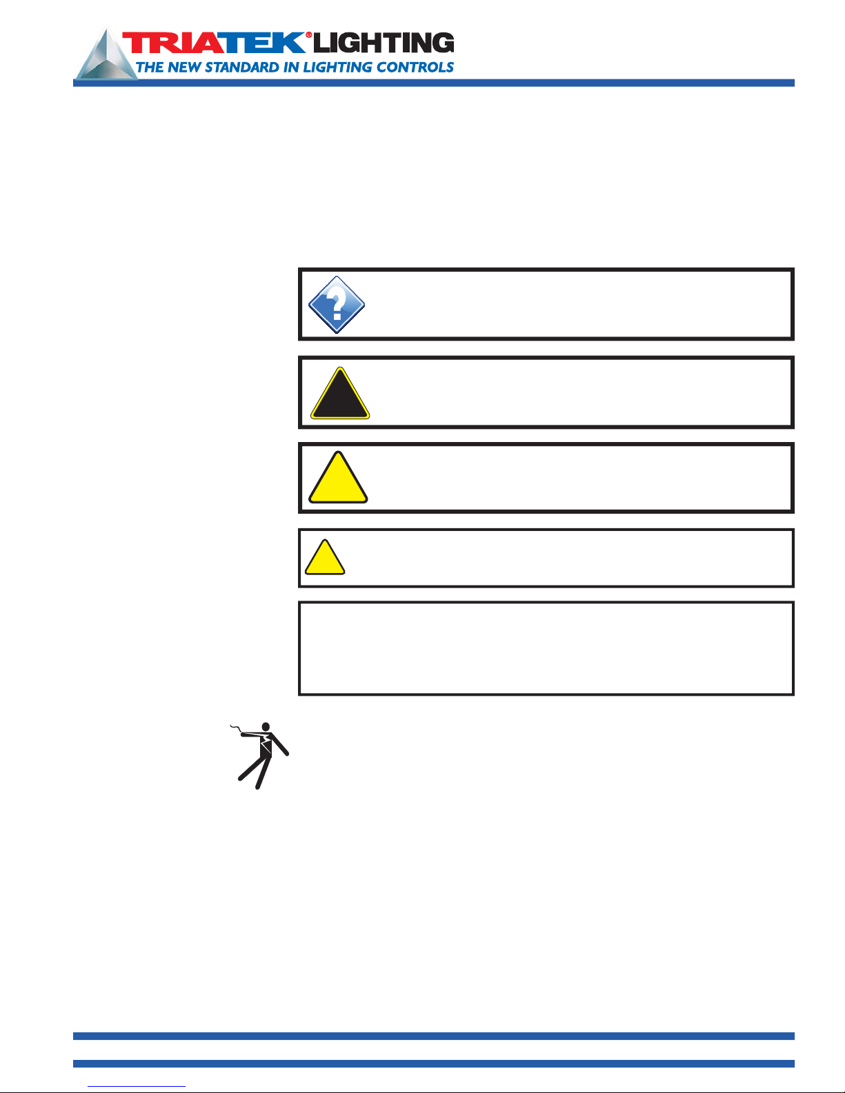
The following safety messages are used throughout this manual to alert of
immediate or potential danger to life or property:
Hint Indicates a tip or trick to help you with setting up or
controlling the BASnet LightView.
DANGER! Indicates an immediately hazardous situation
!
which, if not avoided, will result in death or serious injury.
WARNING! Indicates a potentially hazardous situation
!
which, if not avoided, can result in death or serious injury.
CAUTION: Indicates a potentially hazardous situation which, if not
!
avoided, can result in minor or moderate injury.
CAUTION: Used without the safety alert symbol, indicates a potentially
hazardous situation which, if not avoided, can result in personal or
property damage. Failure to comply with proper handling of the TRIATEK
Lighting products may void your warranty
In addition, this symbol may appear in the margin of specific portions of text as a
safety reminder. Applicable instruction steps will be listed beneath the symbol.
Disclaimer
1025 Cobb Place Blvd. Suite 100 Kennesaw, GA 30144 • 800-241-9173 • www.TRIATEKlighting.com
Instructions contained in this user’s guide should be performed only by qualified
persons in accordance with local and national codes. TRIATEK
its affiliates assume no responsibility for any consequences related to the improper
use of this manual.
®
Lighting, Inc. and
Page 2 of 4105/26/2005
Page 3

BASnet LightView User’s Guide
What’s New in LightView 3.0* ?
(*Present version is called 2.0 in BLV Users Guide.)
New Features
• Dial up modem can be connected to 232 port to serve up the BLV web pages. A selector switch is provided use the
232 port as a console or modem connection.
• Firmware upgrade flash capability. Users can receive a firmware image from TRIATEK Lighting and upload it via the
web interface.
• Import groups from LPPK. Previously, users must set up the panel groups in again in BLV even if they already existed
in the LPPK file. Now the user creates the panel groups just once in LPPK and simply imports them to BLV.
• Multi-event linking for photocells. Previously, multi-lamp lighting events for photocells were not truly linked resulting
conflicting commands sent over the network. Now photocell events can linked in setup to work together. The protocol
establishes the correct command for linked multi-lamp levels used in day lighting.
• Event log e-mail option. Users can specify sender address, destination address, and time when event logs are to be
automatically emailed. An energy manager could thus arrange for event logs from multi-sites to be sent to his office.
• Motion sensor group can be used to qualify photocell event. Previously, this could only be effectively done in
conjunction with hard wire methods to the LMB.
• Lighting groups are now sorted. Previously, the groups were placed at the top of the BLV group list page. This was
cumbersome when groups were inserted later and appeared out of numerical order. Now a new entry is inserted in its
proper order, according to panel and group number even if added later.
• TI-45-Net global commands. Previously, users needed to call in a separate user ID for each panel. Now a special
block of reserved user ID codes can be mapped to multiple panels allowing 1 call to control a BLV Area spanning
several panels.
Improvements
• Enhanced logging capability. Events log increased from 30 to 100. Command log increased from 100 to 500.
• Areas increased from 100 to 250.
• Qualifiers increased from 30 to 100.
• Area names appear at top of group-assignment-to-area page. Previously, the page did not identify which area the
groups were being assigned to.
• Ignore TI-Net override if overtaken by BLV schedule. Previously, if a TI override On was followed by BLV scheduled
ON, the TI would turn Off the circuit during the middle of the scheduled period. Now the TI Off is ignored when
superceded by a BLV schedule.
• BLV no longer automatically times out after 6 minutes of inactivity. The timeout is user adjustable.
• Data base converter. A separate program is available to convert databases made in rev’s 1.0, 2.0, 2.0a, 2.1, and
2.1.1(=3.0).
Hint:
Use the Table of Contents. It is
provided as a map to guide you
through the essential items needed
for your particular application of
LightView.
1025 Cobb Place Blvd. Suite 100 Kennesaw, GA 30144 • 800-241-9173 • www.TRIATEKlighting.com
Page 3 of 4105/26/2005
Page 4

BASnet LightView User’s Guide
What’s Was New in LightView 2.0 ?
• Daylight Savings Time - Pg 38 - When enabled by the user, this feature will automatically change BLV’s clock to Daylight
Savings Time when DST is in effect.
• Six Astronomical Events - Pg 25 - Astronomical Events allow lighting events to be scheduled based on sunrise and
sunset times forecast by LightView. This feature is ideal for scheduling outdoor lighting or appropriate indoor areas that
depend on sunlight illumination.
• Thirty Photocell Events - Pg 24 - Photocell events are used to control lights based on variable sunlight illumination
levels. Up to 30 photocells can be placed at different areas so that lighting can be controlled for daylight harvesting or
outdoor scheduling. BLV also allows specifi cation of a dead band tolerance to prevent spurious triggering of lights.
• Thirty Continuous Qualifi ers - Pg 22 - Earlier versions of LightView only qualifi ed an event once. This new feature
continuously monitors a user-specified group and detects state changes. A state change then triggers user-defi ned
actions on a list of areas. This feature is ideal for installations that require a switched input on one panel to control other
panels.
• Automatic IP Address Discovery - Pg 7- This feature is ideal for users that connect directly to an BLV module using
crossover cables. This allows users to communicate with BLV without reconfi guring their network settings. The process
is initiated by pressing a switch on BLV and then accessing any address within the computer’s subnet from Internet
Explorer. BLV will detect the address requested by Internet Explorer and reconfi gure itself to that address.
• Name up to 1000 Groups - Pg 14 - Earlier versions of LightView control up to 1000 Groups but support assigning a
23-character description to only 254 of the 1000 Groups. The ability to assign 23- character descriptions to up to 1000
Groups is useful for installations that use the “Area and Group Status” feature to override or monitor Group status of an
entire lighting network.
• LPPK with LightView - Pg 47 - LightView 2.0 now interfaces with LPPK to allow users to program all TRIATEK Lighting
panels connected to LightView over the Internet from any remote location.
• Telephone Interface with LightView - Pg 44 - LightView is configured to work with TI-4500-0-Net, TRIATEK’s telephone
override interface. Ti- 4500-0-net with LightView provides up to 8191 password–protected user ID’s and up to 6 hours
of override plus cancellation of on-going override. Voice prompts can be customized by the user.
• Documentation - LightView documentation is presented in two publications: LightView User’s Guide and LightView
Installers Guide. For basic physical installation and wiring, refer to LightView Installer’s Guide. For all other matters, refer
to this publication.
To use LightView successfully, three things must be accomplished:
1) LightView must be installed properly.
2) LightView must be set-up to communicate with a Laptop or PC.
3) Once communication is established, LightView must be programmed to control the lighting panels. Once these three
items are done, LightView can operate either “stand-alone” or remain connected to the workstation or LAN.
To Install LightView:
• Refer to publication, LightView Installation Guide.
To Set-Up LightView:
• Set an IP address in LightView compatible with the subnet of the workstation or LAN.
• Details are covered in this document’s main sections:
Setting Up BLV and Connecting to BLV.
To Program LightView:
• Define the Lighting Panel Groups
• Define the Lighting Areas
• Assign the Panel Groups to the Areas
• Schedule the Areas.
• Details are covered in this document’s main section: Programming BLV.
1025 Cobb Place Blvd. Suite 100 Kennesaw, GA 30144 • 800-241-9173 • www.TRIATEKlighting.com
Page 4 of 4105/26/2005
Page 5

Contents
BASnet LightView User’s Guide
BASnet LightView User’s Guide
What’s Was New in LightView 2.0 ? . . . . . . . . . . . . . . . . . . . . . . . . . . . . . . . . . . . . . . . . . . . . . . . . . . . 3
What’s New in LightView 3.0* ? . . . . . . . . . . . . . . . . . . . . . . . . . . . . . . . . . . . . . . . . . . . . . . . . . . . . . . 4
BASnet LightView Overview . . . . . . . . . . . . . . . . . . . . . . . . . . . . . . . . . . . . . . . . . . . . . . . . . . . . . . . . 6
BASnet LightView Ports and LEDs . . . . . . . . . . . . . . . . . . . . . . . . . . . . . . . . . . . . . . . . . . . . . . . . . . . 7
Setting Up BASnet LightView . . . . . . . . . . . . . . . . . . . . . . . . . . . . . . . . . . . . . . . . . . . . . . . . . . . . . . . 8
Automatic IP Address Discovery . . . . . . . . . . . . . . . . . . . . . . . . . . . . . . . . . . . . . . . . . . . . . . . . . . . . . 8
Confi guring BLV Using a Serial Connection . . . . . . . . . . . . . . . . . . . . . . . . . . . . . . . . . . . . . . . . . . . . . 8
Setting Up Hyperterminal . . . . . . . . . . . . . . . . . . . . . . . . . . . . . . . . . . . . . . . . . . . . . . . . . . . . . . . . 8
Setting Up Network Address . . . . . . . . . . . . . . . . . . . . . . . . . . . . . . . . . . . . . . . . . . . . . . . . . . . . . . . . 9
Setting the Password . . . . . . . . . . . . . . . . . . . . . . . . . . . . . . . . . . . . . . . . . . . . . . . . . . . . . . . . . . . . 10
Connecting to the BASnet LightView . . . . . . . . . . . . . . . . . . . . . . . . . . . . . . . . . . . . . . . . . . . . . . . . 11
Checking the version of Internet Explorer . . . . . . . . . . . . . . . . . . . . . . . . . . . . . . . . . . . . . . . . . . . . . . 11
Logging In. . . . . . . . . . . . . . . . . . . . . . . . . . . . . . . . . . . . . . . . . . . . . . . . . . . . . . . . . . . . . . . . . . . . 11
Navigating the BASnet LightView . . . . . . . . . . . . . . . . . . . . . . . . . . . . . . . . . . . . . . . . . . . . . . . . . . . . 12
Programming the BASnet LightView . . . . . . . . . . . . . . . . . . . . . . . . . . . . . . . . . . . . . . . . . . . . . . . . 13
Defi ning Groups . . . . . . . . . . . . . . . . . . . . . . . . . . . . . . . . . . . . . . . . . . . . . . . . . . . . . . . . . . . . . . . . 13
Creating Areas . . . . . . . . . . . . . . . . . . . . . . . . . . . . . . . . . . . . . . . . . . . . . . . . . . . . . . . . . . . . . . . . . 14
Creating Schedules . . . . . . . . . . . . . . . . . . . . . . . . . . . . . . . . . . . . . . . . . . . . . . . . . . . . . . . . . . . . . . 14
Event Details . . . . . . . . . . . . . . . . . . . . . . . . . . . . . . . . . . . . . . . . . . . . . . . . . . . . . . . . . . . . . . . . . . . 16
Setting the Duration of the Schedule . . . . . . . . . . . . . . . . . . . . . . . . . . . . . . . . . . . . . . . . . . . . . . . . . 16
Using Multiple Day Scheduling . . . . . . . . . . . . . . . . . . . . . . . . . . . . . . . . . . . . . . . . . . . . . . . . . . . . . 16
Using Single Day Scheduling . . . . . . . . . . . . . . . . . . . . . . . . . . . . . . . . . . . . . . . . . . . . . . . . . . . . . . . 16
Setting the Date Range . . . . . . . . . . . . . . . . . . . . . . . . . . . . . . . . . . . . . . . . . . . . . . . . . . . . . . . . . . . 17
Naming the Schedule . . . . . . . . . . . . . . . . . . . . . . . . . . . . . . . . . . . . . . . . . . . . . . . . . . . . . . . . . . . . 17
Event Options . . . . . . . . . . . . . . . . . . . . . . . . . . . . . . . . . . . . . . . . . . . . . . . . . . . . . . . . . . . . . . . . . . 17
Qualifying a Schedule . . . . . . . . . . . . . . . . . . . . . . . . . . . . . . . . . . . . . . . . . . . . . . . . . . . . . . . . . . . . 18
Photocells . . . . . . . . . . . . . . . . . . . . . . . . . . . . . . . . . . . . . . . . . . . . . . . . . . . . . . . . . . . . . . . . . . . . . 19
Astronomical Events . . . . . . . . . . . . . . . . . . . . . . . . . . . . . . . . . . . . . . . . . . . . . . . . . . . . . . . . . . . . . 20
Lighting Area Commands . . . . . . . . . . . . . . . . . . . . . . . . . . . . . . . . . . . . . . . . . . . . . . . . . . . . . . . . . 21
Adding New Areas to the Schedule . . . . . . . . . . . . . . . . . . . . . . . . . . . . . . . . . . . . . . . . . . . . . . . . . . 21
Viewing the Schedule . . . . . . . . . . . . . . . . . . . . . . . . . . . . . . . . . . . . . . . . . . . . . . . . . . . . . . . . . . . . 23
Monitoring and Overriding Areas and Groups . . . . . . . . . . . . . . . . . . . . . . . . . . . . . . . . . . . . . . . . . .24
Viewing Cause Data . . . . . . . . . . . . . . . . . . . . . . . . . . . . . . . . . . . . . . . . . . . . . . . . . . . . . . . . . . . . . 25
Viewing Graphics . . . . . . . . . . . . . . . . . . . . . . . . . . . . . . . . . . . . . . . . . . . . . . . . . . . . . . . . . . . . . . . 25
Creating Holidays . . . . . . . . . . . . . . . . . . . . . . . . . . . . . . . . . . . . . . . . . . . . . . . . . . . . . . . . . . . . . . . 26
Viewing System Log . . . . . . . . . . . . . . . . . . . . . . . . . . . . . . . . . . . . . . . . . . . . . . . . . . . . . . . . . . . . . 27
System Setup . . . . . . . . . . . . . . . . . . . . . . . . . . . . . . . . . . . . . . . . . . . . . . . . . . . . . . . . . . . . . . . . . . 27
Setting Coordinates and the Internal Clock . . . . . . . . . . . . . . . . . . . . . . . . . . . . . . . . . . . . . . . . . . . . 28
Setting IP Confi guration . . . . . . . . . . . . . . . . . . . . . . . . . . . . . . . . . . . . . . . . . . . . . . . . . . . . . . . . . . . 28
Uploading Graphics . . . . . . . . . . . . . . . . . . . . . . . . . . . . . . . . . . . . . . . . . . . . . . . . . . . . . . . . . . . . . . 29
Backup and Restoration of Data . . . . . . . . . . . . . . . . . . . . . . . . . . . . . . . . . . . . . . . . . . . . . . . . . . . . 29
Backing Up Data . . . . . . . . . . . . . . . . . . . . . . . . . . . . . . . . . . . . . . . . . . . . . . . . . . . . . . . . . . . . . . 29
Restoring Data. . . . . . . . . . . . . . . . . . . . . . . . . . . . . . . . . . . . . . . . . . . . . . . . . . . . . . . . . . . . . . . . . 30
Deleting the System Database . . . . . . . . . . . . . . . . . . . . . . . . . . . . . . . . . . . . . . . . . . . . . . . . . . . . . . 31
Telephone Override with BASnet LightView . . . . . . . . . . . . . . . . . . . . . . . . . . . . . . . . . . . . . . . . . . 31
Assigning Codes. . . . . . . . . . . . . . . . . . . . . . . . . . . . . . . . . . . . . . . . . . . . . . . . . . . . . . . . . . . . . . . . 31
Range of ID Numbers . . . . . . . . . . . . . . . . . . . . . . . . . . . . . . . . . . . . . . . . . . . . . . . . . . . . . . . . . . . . 32
Steps to Setup TI-4500-NET . . . . . . . . . . . . . . . . . . . . . . . . . . . . . . . . . . . . . . . . . . . . . . . . . . . . . . . 32
Wiring Diagram . . . . . . . . . . . . . . . . . . . . . . . . . . . . . . . . . . . . . . . . . . . . . . . . . . . . . . . . . . . . . . . . . 33
LPPK with BASnet LightView . . . . . . . . . . . . . . . . . . . . . . . . . . . . . . . . . . . . . . . . . . . . . . . . . . . . . . 34
BASnet LightView Programming Worksheets
Area and Group Assignments . . . . . . . . . . . . . . . . . . . . . . . . . . . . . . . . . . . . . . . . . . . . . . . . . . . . . 35
Holidays . . . . . . . . . . . . . . . . . . . . . . . . . . . . . . . . . . . . . . . . . . . . . . . . . . . . . . . . . . . . . . . . . . . . . . 36
Schedules. . . . . . . . . . . . . . . . . . . . . . . . . . . . . . . . . . . . . . . . . . . . . . . . . . . . . . . . . . . . . . . . . . . . . 37
Latitued and Longitude Reference . . . . . . . . . . . . . . . . . . . . . . . . . . . . . . . . . . . . . . . . . . . . . . . . . . 35
. . . . . . . . . . . . . . . . . . . . . . . . . . . . . . . . . . . . . . . . . 35
1025 Cobb Place Blvd. Suite 100 Kennesaw, GA 30144 • 800-241-9173 • www.TRIATEKlighting.com
Page 5 of 4105/26/2005
Page 6
BASnet LightView User’s Guide
BASnet LightView Overview
The BASnet® LightView™ (BLV) is a Web-based programming system that enables lighting control from an internet
browser. The browser functions to execute scheduled event commands upon pre-defined lighting areas. These areas
can be planned and designed with the use of worksheets, and they then can be entered into the module via BLV system.
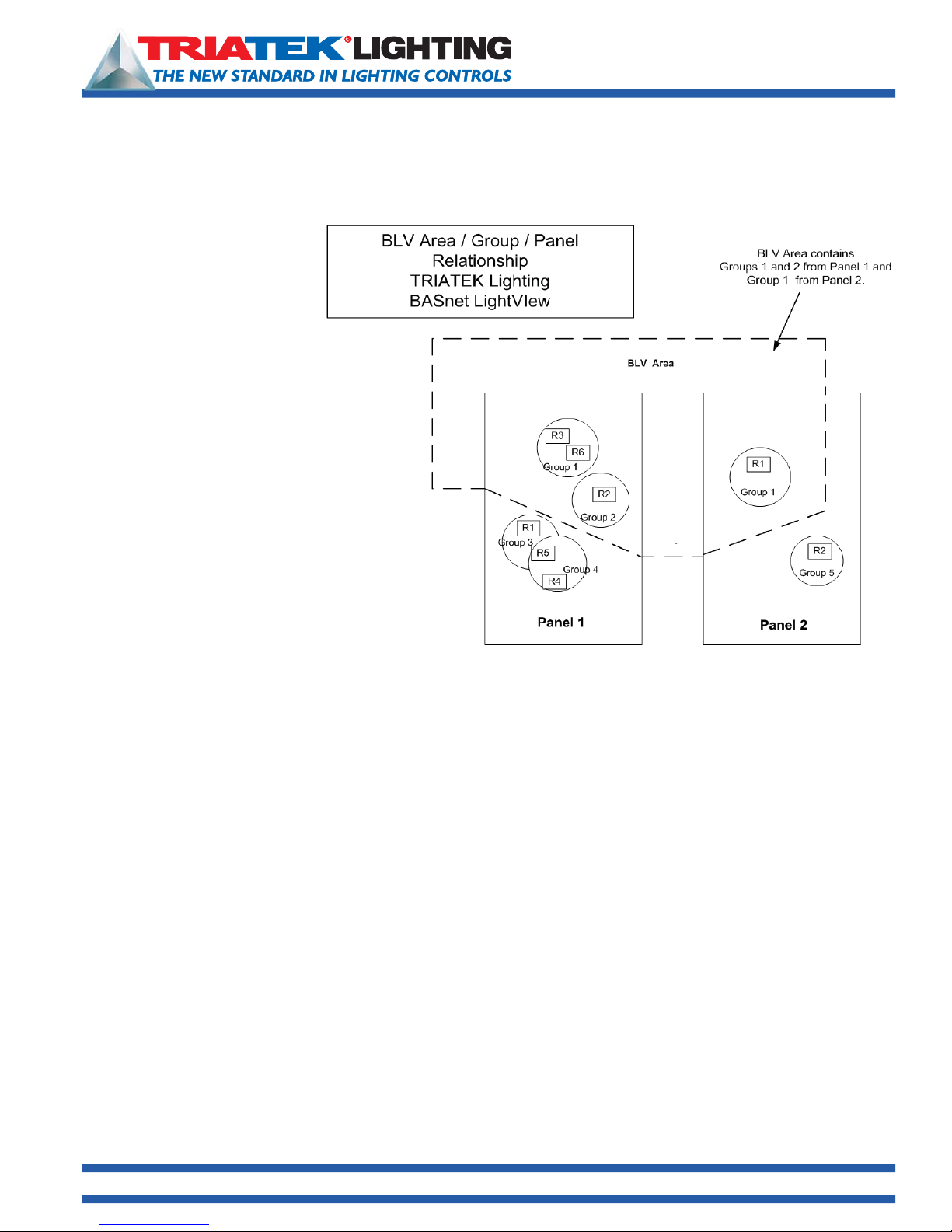
BLV’s functionality is based on
a structure that utilizes lighting
panels, groups and areas. This
structure provides a logical
and organized system. Their
relationship is defined briefly
as follows: Lighting areas are
composed of one or more lighting
groups, and lighting groups are
composed of one or more relays in
a lighting panel. Each lighting panel
employed by BLV has its own
groups assigned to it. A lighting
group never spans multiple lighting
panels. The browser can handle
schedules for up to (inclusive) 100
lighting areas, and 1000 lighting
groups. The system allows the
user to input, change and view all
information related to the lighting
areas.
A summary of the systems components and associated functionality follows:
1.) The Main Menu of links to all pages in the system.
2.) Lighting Groups Assignment where groups are assigned to panels.
3.) Lighting Area Assignment where areas are created and groups are assigned to areas.
4.) Scheduling Events where areas are given actions to perform and grouped by time the actions occur.
5.) Viewing Events of all schedules in the system.
6.) “Today’s” Event List displays the events scheduled to occur that day.
7.) Holiday List page provides addition and modification of holidays into the system.
8.) Area and Group Status displays the current ON/OFF states of the areas and groups, allows manual override of the areas
and groups, and uploaded maps can be viewed.
9.) System Setup includes system clock alteration, Network address configuration, upload maps, backup and restoration of
system database, and deletion of database.
10.) System Logs records any phenomena related to a schedule and an area including creation, modification, and qualification
of schedules and success or failure of action on areas, along with the time stamp of these phenomena.
11.) BASnet LightView is able to receive telephone override commands from TRIATEK’s TI-4500-NET telephone interface
module. See pages 31-33 for details.
12.) BASnet LightView interfaces with LPPK to allow users to program lighting panels connected to BASnet LightView over
the Internet from any remote location.
1025 Cobb Place Blvd. Suite 100 Kennesaw, GA 30144 • 800-241-9173 • www.TRIATEKlighting.com
Page 6 of 4105/26/2005
Page 7
BASnet LightView User’s Guide
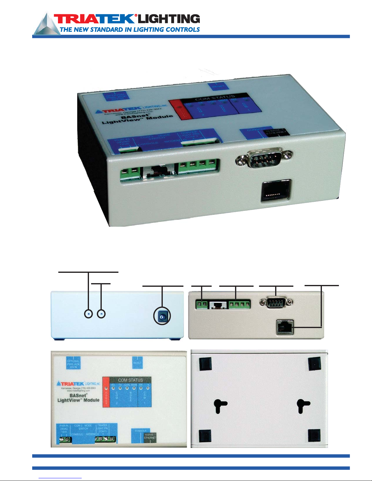
Auto IP Discovery
Reset
Optional
Power Jack
24vdc
Power
24vdc
COM1
RS-485
DB9-M
RS-232
Serial Port
RJ-45
Ethernet
Port
1025 Cobb Place Blvd. Suite 100 Kennesaw, GA 30144 • 800-241-9173 • www.TRIATEKlighting.com
Page 7 of 4105/26/2005
Page 8
BASnet LightView User’s Guide
Setting Up BASnet LightView
Automatic IP Address Discovery This feature is ideal for users that connect directly to BLV modules using crossover
cables. This allows users to communicate with BLV without reconfiguring the network settings on their laptop or
PC. LightView will configure its IP address to be compatible with the user’s laptop. Use this feature only with direct
connections to BLV.
To use Automatic IP Address Discovery:
• Determine the network IP address of the laptop or PC. Typically, right click “My Network Places” then select Properties.
• Next, select TCP/IP for the ethernet card and then click on the Properties button.
• Connect Laptop or PC to BLV using ethernet cross-over (“null modem”) CAT5 cable.
• Open Internet Explorer
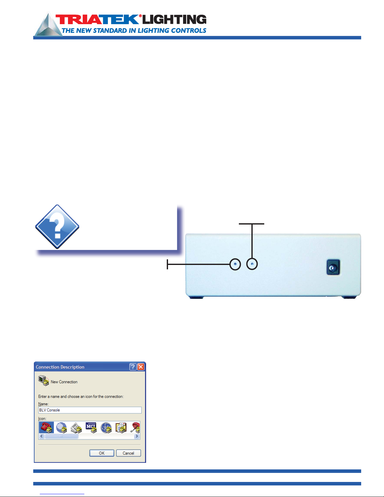
• Depress the auto discovery Switch in BLV. See diagram below.
• On the address bar at the top of the Internet Explorer page, enter an IP address within the range of the laptop’s subnet.
• LightView will reconfigure itself to an IP compatible with the laptop’s address.
Hint:
Push pin through this hole
to activate internal switch for
automatic IP discovery. Use this
feature only with direct connections
to BLV.
Reset
Auto IP Discovery
Configuring BLV Using Serial Console
When Auto IP Discovery cannot be used, set the IP via BLV’s serial console and HyperTerminal. The RS-232 serial
programming cable is used to set initial low-level system settings such as network addresses and the browser password
with a serial console program. It is not necessary to use the serial interface for any future changes of the network
addresses because the LightView Browser can be used for this purpose. (See “Setting IP Configuration” on page 28).
The browser password, however, can only be changed through the serial console interface. HyperTerminal, which comes
standard with most if not all current versions of Microsoft® Windows® is a serial console program that can be used to
change the low-level settings.
The first window that displays in HyperTerminal is the Connection Description
Setting Up HyperTerminal
In order to communicate to the BLV module, the IP, gateway, subnet mask
and name server addresses need to be changed. To change each of
these settings, firstly, run a terminal program. The example to the left uses
HyperTerminal. HyperTerminal can normally be found in Windows Accessories
under Communications.
window shown to the left. Name the connection, select an icon, and click
“OK”. In the next window shown below, select the Communications port the
RS-232 cable is connected to on the host computer, and click “OK”.
1025 Cobb Place Blvd. Suite 100 Kennesaw, GA 30144 • 800-241-9173 • www.TRIATEKlighting.com
Page 8 of 4105/26/2005
Page 9
BASnet LightView User’s Guide
Setting Up BASnet LightView
Setting Up HyperTerminal (continued)
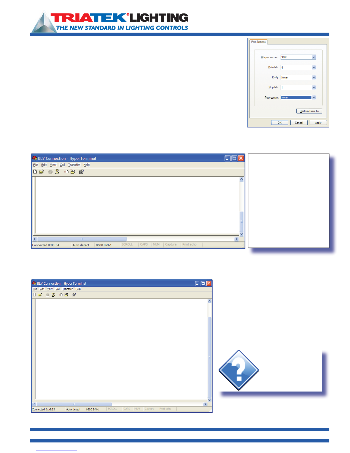
Next, specify communications port information used with the communications port is
entered in the “... Properties” window. Select the same values used below and click
“OK”. These values are required for proper communication with the BLV module. For
information concerning the meaning of each field refer to HyperTerminal documentation.
If using another terminal program, the format of the fields into which the data is entered
will be different, but the same information will need to be supplied.
Setting Network Address
After providing the proper communications port settings, the terminal window will open. The “set” command is used to
input the network settings which have associated variables. The list of variables and how the “
change the variables can be viewed by using the “
help set
set:
Usage: “set <variable> <value>”
The following variable can be set with this command:
ip - The IP address of the device (ie: w.x.y.z)
netmask - The netmask for the device (ie: 255.255.255.0)
hostname - The hostname of the device (ie: w.x.y.z)
nameserver - The nameserver for the device (ie: w.x.y.z)
help” command. Enter “help set” from the keyboard as shown below:
set” command is used to
Note: TRIATEK Lighting ships
the BLV module with default
network settings. If the module
will be installed on a LAN these
settings must be changed. The
default settings are as follows:
IP address: 192.1.1.1
Netmask: 255.255.255.0
Gateway: 192.1.1.1
Nameserver: 192.1.1.1
Based on help’s information shown above the user would, as an example, set the IP address by entering “
199.250.185.179”. Each variable listed in help is assigned values in the same manner according to the usage given. The
window below shows all network variables being set.
All current values of the network variables
can be viewed by using the “show config”
command. This command can be used
at any point during the console session. It
hostname - The hostname of the device (ie: w.x.y.z)
nameserver - The nameserver for the device (ie: w.x.y.z)
OK
set ip 199.250.185.179
IPOK
set netmask 255.255.255.0
NeOK
set gatgeway 199.250.185.2
GaOK
set nameserver 199.250.185.2
Name Servers set to: 199.250.185.2
can be used to view the settings before any
changes are made and after each and all
variables are set.
Hint:
Use the HyperTerminal
“show config” command
to display or validate the
current configuration
settings.
set ip
1025 Cobb Place Blvd. Suite 100 Kennesaw, GA 30144 • 800-241-9173 • www.TRIATEKlighting.com
Page 9 of 4105/26/2005
Page 10
BASnet LightView User’s Guide
Setting Up BASnet LightView
Setting the Password
Unlike the network variables, the password used to enter the BLV system can only be set through the RS-232 serial
connection. Not allowing the password to be changed from the browser is a security feature that keeps the password in
a single secure location, and this in turn prevents an unintended user who has not been granted access to the physical
module from changing the password from another user’s browser. It is much easier for someone to change the password
from a user’s opened browser window than actually getting access to the physical module and an RS-232 cable.
Like the network variables, the password can be set using the “set” command, however, set’s usage with the password
variable differs from the usage of set with the network variables.
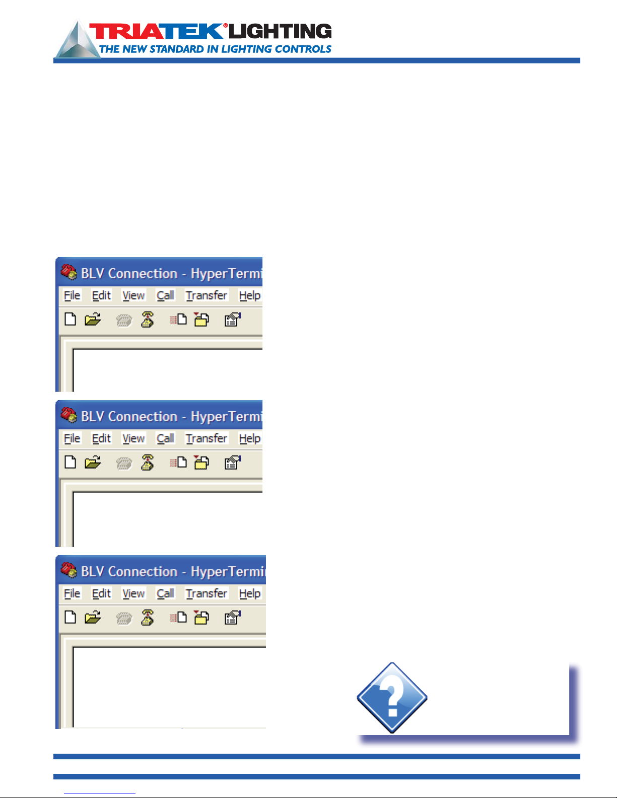
To change the password enter only “set password” and then press the Enter key on the keyboard. The program will then
bring the user through a set of prompts to change the password. The program first prompts the user for the old password:
set password
Enter old password
set password
Enter old password
Error 1001 Incorrect password
Now enter the old password and press the enter key. If the old
password is entered incorrectly it will generate an error:
Each time an error is generated, “set password” must be entered again.
The program will then compare the entered password with the actual
password. If the old password is entered correctly, the program will
report “Password Verified”, and then prompt the user to enter the new
password:
set password
Enter old password
Password verified
Enter new password
1025 Cobb Place Blvd. Suite 100 Kennesaw, GA 30144 • 800-241-9173 • www.TRIATEKlighting.com
Passwords can be a maximum length of any 9 keyboard characters.
Hint:
If the new password entered
is more then 9 characters
HyperTerminal will respond with
“ERROR 1000 9 character
password limit”
Page 10 of 4105/26/2005
Page 11
Setting Up BASnet LightView
Setting the Password (continued)
BASnet LightView User’s Guide
After entering a new password that is less than or equal to 9 characters,
the program will then request the user to reenter the new password to
verify that the new password is the intended password of the user.
set password
Enter old password
Password verified
Enter new password
Reenter new password
Password set
OK
After reentering the password correctly, the program will accept, giving
the conformation message “Password set”, and make the password
change. The user can now connect and login to the BLV.
Connecting to BASnet LightView
Checking the Version of Internet Explorer
Before running the browser ensure Microsoft® Internet Explorer
5.5 Service Pack 2 or a later version of Internet Explorer is
employed to run. This information can be found by running
Microsoft® Internet Explorer, going to “Help” in the menu bar,
and then selecting “About Internet Explorer”. See “Version” and
“Update Version” in the graphic to the right:
Hint:
Microsoft offers the Internet
Explorer brower and all
updates for free on it’s
download website.
http://www.microsoft.com/
Hint:
If the new password entered does not match
the first password HyperTerminal will respond
with “ERROR 1002 Passwords do not match”
You will need to restart the “set password”
process to proceed
1025 Cobb Place Blvd. Suite 100 Kennesaw, GA 30144 • 800-241-9173 • www.TRIATEKlighting.com
Logging In
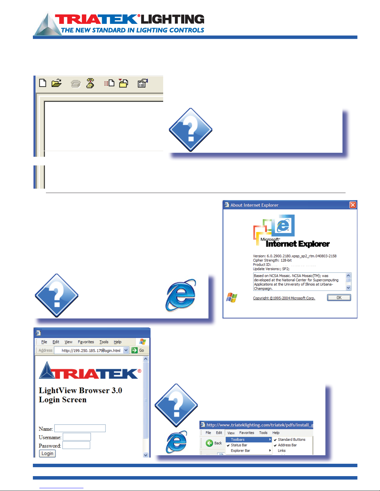
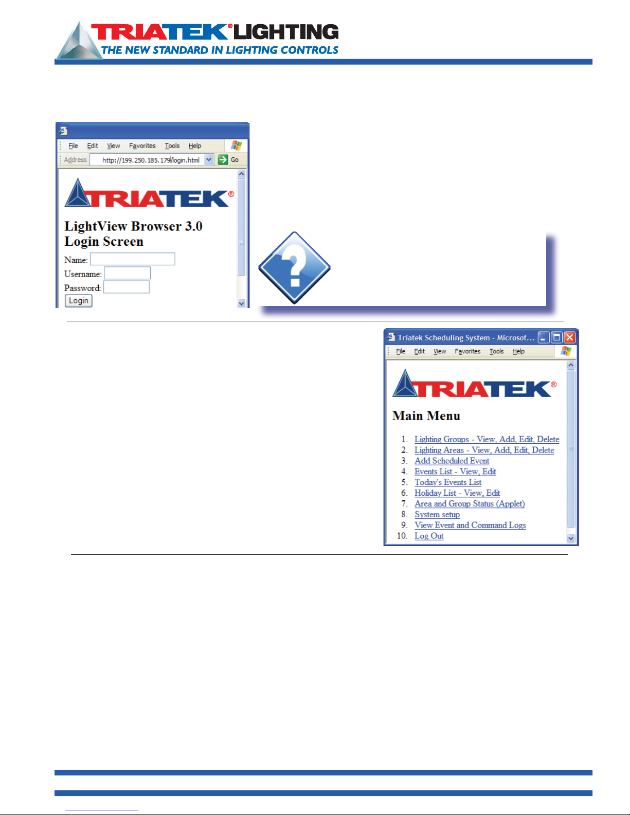
The BLV system can be reached by entering the IP address of the
LightView module in the URL window of the users internet browser and
then hitting [Enter ] on the keyboard or clicking the “Go” button on
the browser next to the address text box. The first page of the system
displayed (left) is the login page.
Hint:
If you cannot see the URL window on your
browser, you can make it visible by selecting
View Toolbars Address Bar
(make sure there's a next to "Address Bar”)
Page 11 of 4105/26/2005
Page 12
Setting Up BASnet LightView
Logging In (continued)
Navigating the BASnet LightView
BASnet LightView User’s Guide
To login, the user should enter their name or some form of identification in
the Name box. The username and password, initially are given by TRIATEK
Lighting. The user’s name is always “manager”, and the password is set to
“password”. The password should be changed by the company for security.
For instructions on how to change the password, refer to “Setting the
Password” on page 10. Enter the username and password in the text boxes
provided.
Hint:
Since the same factory default password is
provided with all BASnet LightView modules,
the installer should promptly change the
password upon installation to prevent
unauthorized access to the lighting controls.
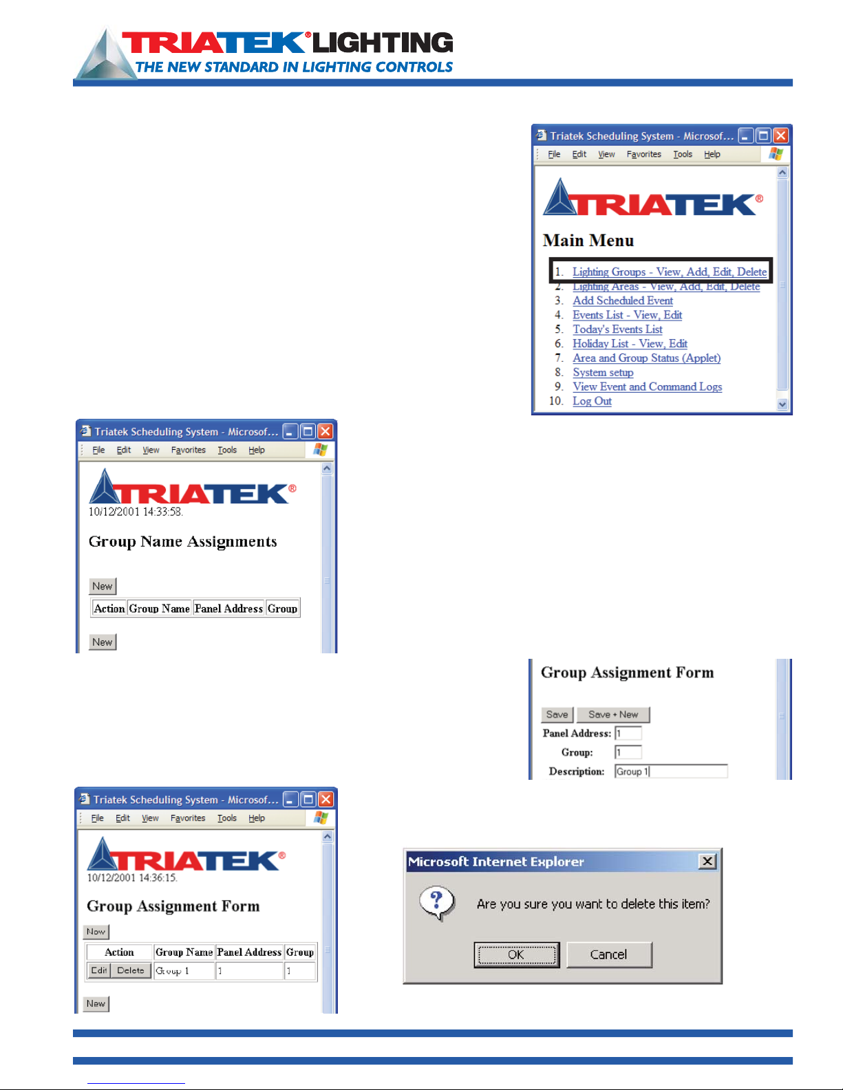
Once the username and password are given, click the ‘Login’ button. The
user is then brought to the main menu (right).
From this menu the user can reach all pages of the browser. In addition,
most pages in the system provide the capability to reach all other pages
by a menu of page links at the bottom of the page. The page menus can
be used in conjunction with the back and forward buttons to enable easy
navigation throughout the system.
1025 Cobb Place Blvd. Suite 100 Kennesaw, GA 30144 • 800-241-9173 • www.TRIATEKlighting.com
Page 12 of 4105/26/2005
Page 13
BASnet LightView User’s Guide
Programming the BASnet LightView
Defining Groups
Defining the lighting groups for each TRIATEK lighting control panel is the
fi rst step to program the browser. Each group is assigned relays using the
TRIATEK LPPK software. For instructions on how to assign relays to groups
see the “LP Controller Users Guide”.
Even though groups have already been created using LPPK they need to be
entered into BLV in order that
1) they can be controlled by BLV, and
2) they are necessary for the creation of areas. The input process involves
assigning a name to a group and the panel the group belongs to.
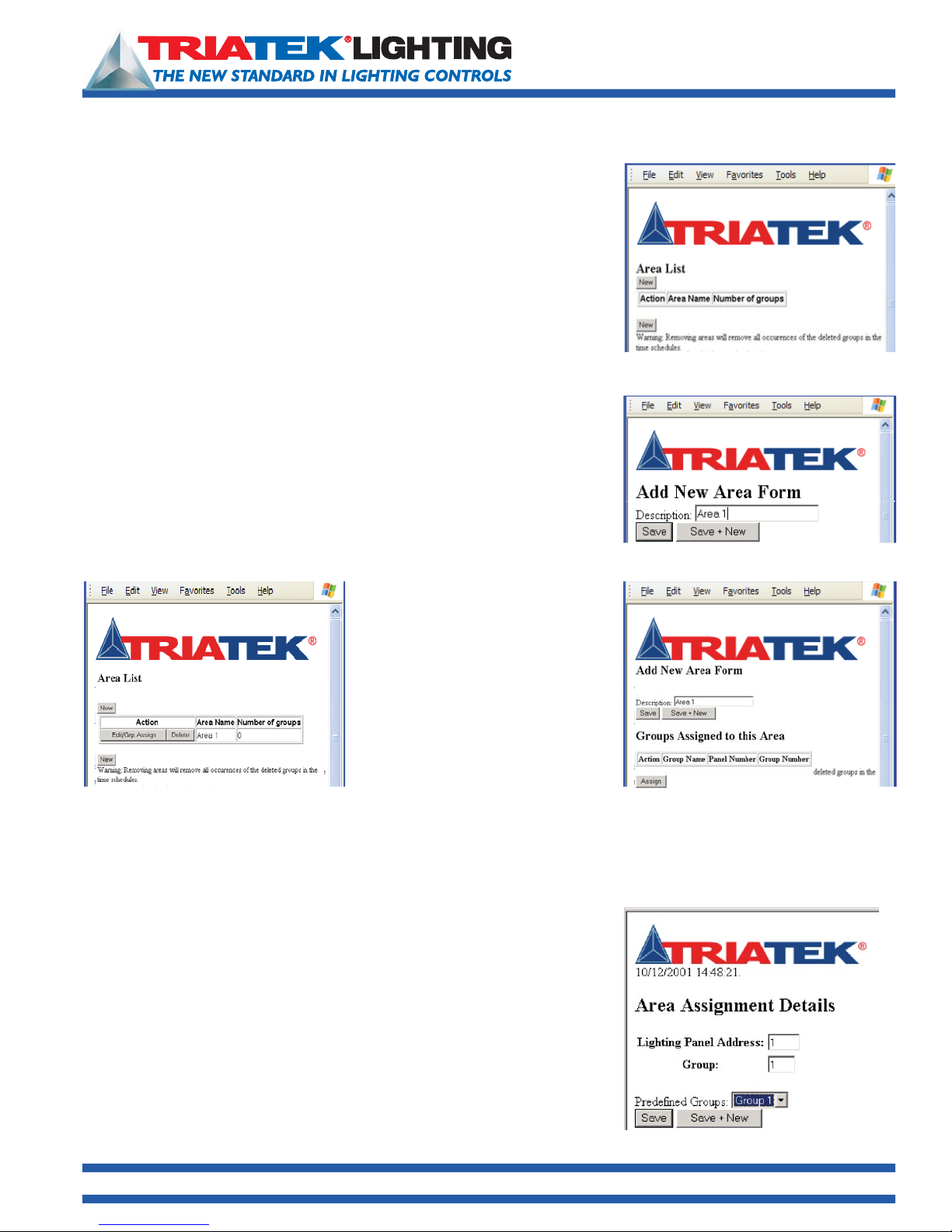
To input the defined groups with their associated panels, from the main
menu, click on ‘
Group Name Assignments’ page. From this series of pages the groups
the ‘
can be defined with their associated panels.
Lighting Groups - View, Add, Edit, Delete’. This will lead to
To begin defining, click the new button and the “Group Assignment Form”
page will appear. On this page enter the panel and group numbers in the
text boxes along with the description.
See “Naming the Schedule” on page 17 for a discussion on naming
conventions in BLV.
Group name descriptions are limited to 23 characters.
The BASnet LightView is capable of addressing up to 1000 groups.
To save this item and return to the list of group name assignments, click the
save button. If you would like to add more groups without returning to the
Group list click the ‘save + new’ button.
Once all of the groups have been assigned to the panels here, all groups
can then be viewed on the ‘
contain a list created of the recently added groups.
Group Name Assignments’ page which will now
From this page group assignments can be edited or deleted. Clicking the
delete button will bring up a confirmation window to prevent accidental
deletes.
1025 Cobb Place Blvd. Suite 100 Kennesaw, GA 30144 • 800-241-9173 • www.TRIATEKlighting.com
This feature is included in all pages of the system containing a delete option.
Page 13 of 4105/26/2005
Page 14
BASnet LightView User’s Guide
Programming the BASnet LightView
Creating Areas
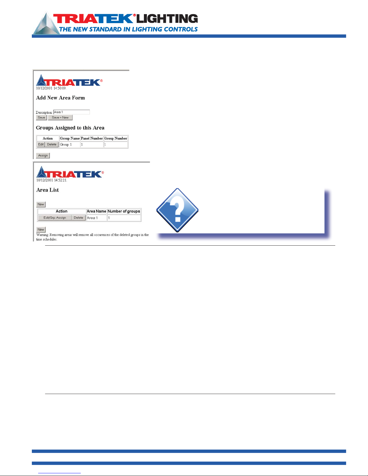
Following group assignment, areas can be created.
Areas are defined as one or more lighting groups to be controlled. Areas are
created beginning in the ‘
Area List’ page.
This page can be reached from the ‘
or simply ‘Lighting Areas’ from another page menu.
To create areas, click the new button, enter the description name in the ‘Add
New Area Form’ page, and click either the ‘Save’ button to return to the Area
List age where the newly created areas will be displayed, or the ‘Save + New’
button to name more areas.
Naming the Schedule” on page 17 for a additional information on naming
See “
conventions in BASnet LightView.
The new areas will show the area name and the number of groups that have
been assigned to area. At this point no groups have been assigned, and the
number will read 0. (example displayed below)
Lighting Areas - View, Add, Edit, Delete’ link,
The displayed areas have an edit and
delete button. The edit button at this
stage allows the user to change the
description of the area. As mentioned
previously if the user chooses to delete
the area confi rmation will be requested,
moreover, on this page a warning is
given. The warning informs the user
that deleting an area here will delete
all occurrences of that area in the BLV
system. The main concern will be the
area being deleted from the event list
which is described later.
Now these areas need groups assigned to them. Refer to the graphic above. The ‘Edit/Grp. Assign’ button enables adding
one or more of the pre-defi ned groups to an area. Click the ‘Edit/Grp. Assign’ button of an area and the ‘Add new area
form’ page will display now with a section called “
‘Assign’ button is given to assign groups to the area listed. The area description
can be edited here as well.
Click the ‘Assign’ button. The ‘Area Assignment Details’ page then appears.
Select one of the predefined groups and select ‘save’ to add only one group to
this area or ‘save + new’ to add additional groups to this area.
1025 Cobb Place Blvd. Suite 100 Kennesaw, GA 30144 • 800-241-9173 • www.TRIATEKlighting.com
Groups Assigned to this area”. Along with the column headings an
Page 14 of 4105/26/2005
Page 15
Programming the BASnet LightView
Creating Areas (continued)
The Add New Area Form will display again but now with the new group and its panel
and group number with it.
• To edit the group added to this area click the ‘
• To delete the group, click the ‘delete’ button.
Additional groups can also be added to this area by clicking the ‘Assign’ button and
repeating the previous steps.
To now save the area with its new group and return to the Area list to view all
created areas, click ‘save’. New areascan be created from this current page without
returning to the ‘Area List page’.
Click the ‘Save + New’ button to create more areas.
BASnet LightView User’s Guide
edit’ button.
Hint:
Once all groups are assigned to areas, the
Area List page with the area description and
the number of groups assigned with them will
display. A maximum of 250 areas that can be
defined.
Creating Schedules
Now that the areas with their respective groups have been created, the last series of steps involve programming the
browser to make schedules of events with the areas.
A schedule is where areas are grouped together to perform action commands at the same point of time and for the same
duration of time. A schedule is given one start and end time on which to perform the start and end action of each area
controlled in the schedule. A schedule may contain one or more areas to control, and each area in the schedule can be
assigned ON, OFF, or DO NOTHING actions.
Time in the schedules is displayed and processed as military time. A unique feature of scheduling in BASnet LightView is
that more than one area can be assigned to the same schedule. Many of our competitors require a separate schedule for
each area. When a large number of areas need to be controlled, multiple-area scheduling can prove to be a more fl exible
solution that saves time and energy because the number of programming operations performed by the user is reduced
considerably.
To create a scheduled event click the ‘Add Scheduled Event’ link if you are in the main menu or ‘Add Event’ link if on
another page in the system. Both are linked to the same page. This page has two sections: Event Details and Lighting Area
Commands.
1025 Cobb Place Blvd. Suite 100 Kennesaw, GA 30144 • 800-241-9173 • www.TRIATEKlighting.com
Page 15 of 4105/26/2005
Page 16
Programming the BASnet LightView
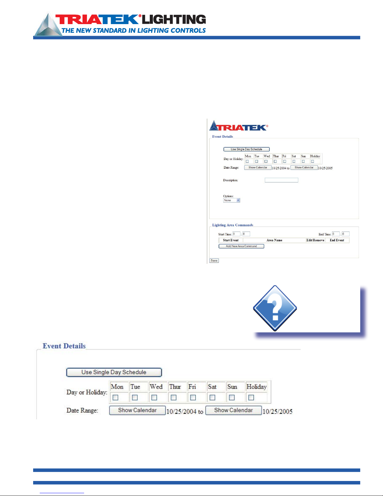
Event Details
BASnet LightView User’s Guide
To edit the group added to this area click the ‘
can also be added to this area by clicking the ‘Assign’ button and repeating the previous steps. To now save the area with
its new group and return to the Area list to view all created areas, click ‘
page without returning to the ‘Area List page’. Click the ‘Save + New’ button to create more areas.
Setting the Duration of the Schedule
The fi rst button in the Event Details section is the ‘Use Single
Day Schedule/Use Multiple Day Schedule’ button. It is a single
button that performs two functions. The ‘Use Multiple Day’
function allows the user to input multiple days in a week on
which the schedule will execute and then set a duration via the
date range. The ‘Use Single Day’ function allows the user to
schedule for one day and set the date the schedule will execute
on.
Using Multiple Day Scheduling
When the page is fi rst viewed the button reads ‘
Schedule’, and below the button is an associated row of boxes
for each day of the week and a holiday box. Click each box that
the schedule is to execute on. The Holiday box is included here
to give the user the option of controlling whether or not BLV will
execute lighting commands on a holiday. By default the system
executes no action on a holiday (See ‘Holidays’ below to learn
how to program holidays into BLV.). Clicking the holiday box here tells BLV to execute the lighting commands even if the current
day is a holiday. In order to ensure that the schedule executes on a holiday check the holiday box; otherwise, leave it blank.
edit’ button. To delete the group, click the ‘delete’ button. Additional groups
save’. New areas can be created from this current
Use Single Day
Using Single Day Scheduling
To use a single day schedule click the “Use Single Day Schedule” button.
As soon as the button is pushed the boxes for the days of the week disappear
and the button will read ‘Use Multiple Day Schedule’ as shown below.
Hint:
Single Day scheduling
is typically used only
when testing the
browser & schedule.
1025 Cobb Place Blvd. Suite 100 Kennesaw, GA 30144 • 800-241-9173 • www.TRIATEKlighting.com
Page 16 of 4105/26/2005
Page 17
BASnet LightView User’s Guide
Programming the BASnet LightView
Setting the Date Range
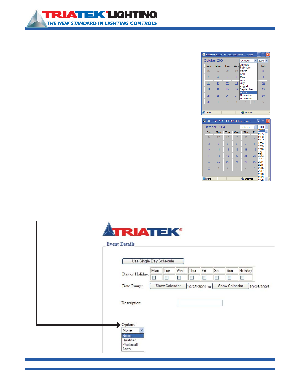
Below the “Single”/”Multiple” day section, is the date range. Single and multiple
day scheduling also affects the appearance of the date range. When single day
scheduling is selected only one day is needed, therefore one date with its calendar
button disappears, and the single date is left. The date range consists of two dates,
each with a ‘show calendar’ button. When the show calendar button is clicked a
calendar displays that allows the user to select the month, year and day desired.
Once the calendar appears, fi rst select the desired month and year. The order of
these two does not matter. Then, select the day the schedule will begin to execute.
If single day scheduling is chosen, there will only be one date in the range; this will
be the only day to select. For a multiple day schedule repeat these steps for the end
of range.
Naming the Schedule
The Schedule is named in the text box adjacent to “
Schedules can be according to the programmers needs and preference. Naming
of the schedules matches that of groups and areas, i.e., it is best to give them
meaningful names, names that describe what they are commanding. For example,
if all hallway lights are included in a schedule, an appropriate schedule description
could be simply, “all hallways schedule”. Naming the schedules also depends
on the number and complexity of the lighting areas. If only a few areas are being
programmed by only a few schedules they could be named, ‘Schedule 1, Schedule
2, etc.’ To name the schedule enter the name of the schedule into the ‘Description’
text box. The description can be a maximum of 23 characters. Selecting month and year
Description” in Event Details.
Event Options
Before creating the scheduled events for areas, consider the scheduled event options: Qualifier, Photo, and Astro. The
option chosen generally governs how the scheduled event will be activated. Use the Options button in the Event Details
box to select the feature. Select “None” if options are not to be used. Each option is explained on the following page.
Select Event Options here
1025 Cobb Place Blvd. Suite 100 Kennesaw, GA 30144 • 800-241-9173 • www.TRIATEKlighting.com
Page 17 of 4105/26/2005
Page 18
Programming the BASnet LightView
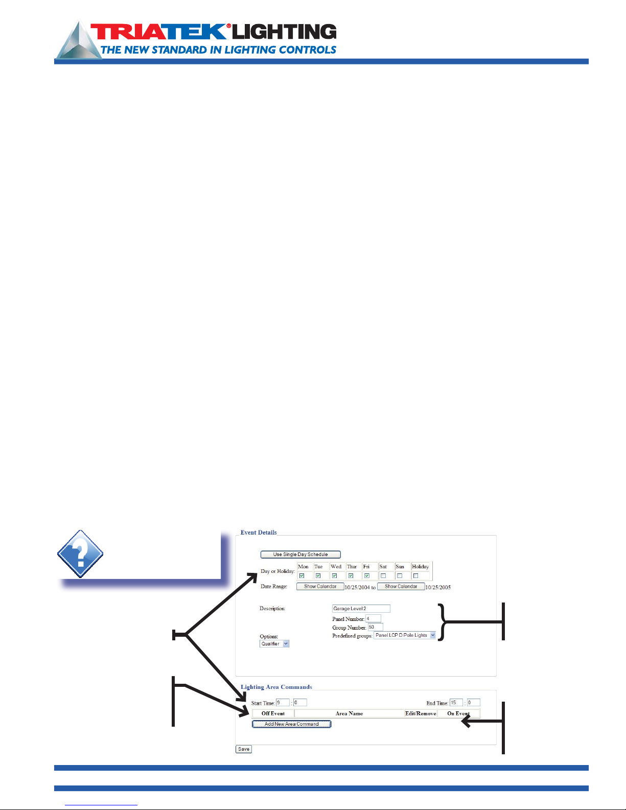
Qualifying a Schedule (Thirty Qualifiers Available)
BASnet LightView User’s Guide
Select “
schedule with a qualifi er, the user must specify a panel and group to act as the qualifier. The scheduled event will not
execute until the qualifier group changes state. i.e., the scheduled event defi nes a “window” of time and once inside
that window, the schedule continuously monitors the qualifier group to detect a state change. Only if the state change is
detected, will the scheduled event be carried out.
Switch inputs can be used to enable a qualifier. Typically, lighting panels have switch inputs assigned to groups that are
assigned to relays. Inputs from building alarm, card access, and motion detector systems are ideal inputs into the lighting
panel to enable groups for use as qualifiers. This feature is ideal for installations that require a switched input on one panel
to control groups in other panels.
Make sure that groups defined as qualifiers are not given Serial On Priority using TRIATEK Setup software, LPPK. The
Qualifier group is directly controlled only by switch, not serial, commands. However, if the Qualifi er group is setup in LPPK
with Serial-On priority enabled, switch inputs to the same group will not be able to control the group when preceded by
Serial On command.
To use qualifier:
• Go to Main Menu Add Scheduled Event Options (in Event Details Section) Qualifier.
• Enter the panel and group manually in the boxes or click the arrow and select from the predefined group list box.
• In Lighting Area Commands section of the same page, set the Start and End times for this particular event. You may set
0:00 and 24:00 for no restrictions.
• Select Add New Area Command.
• Under Area Name, select Edit, and then from pull-down box select a predefined Area.
• From Area Name box, select a predefi ned area.
• From Off Event box, select what the event will do when the qualifi er group is off. For example, if “On” is selected in the
Off Event box, then the event will turn the scheduled area on when the qualifier transitions to off state.
• From On Event box, select what the event will do when the qualifier group is
on. For example, if “Off “ is selected in the On Event box, then the event will turn the scheduled area off when the qualifier
transitions to on state.
• Click the Save button at the bottom of the page to save these settings in LightView.
Qualifier” to use the state change of a group to enable a scheduled event to act on an area. When creating a
Hint:
Remember to click “Save”
prior to closing browser
window.
Event days & times
Select what action
to perform when
the qualifi er group
is “Off”
1025 Cobb Place Blvd. Suite 100 Kennesaw, GA 30144 • 800-241-9173 • www.TRIATEKlighting.com
Qualifer group
defi ned with these
parameters
Select what action
to perform when
the qualifer group
is “On”
Page 18 of 4105/26/2005
Page 19
BASnet LightView User’s Guide
Programming the BASnet LightView
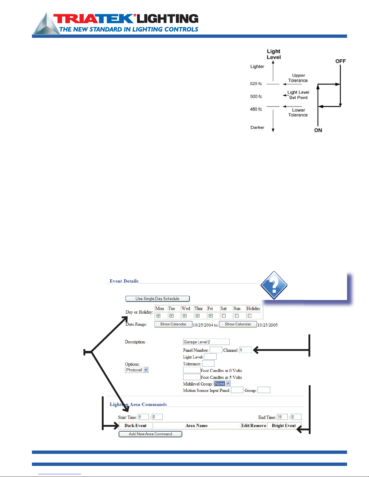
Photocell (Thirty Photocells Available)
Select the “Photocell” option to have an event control a lighting area based on
variable sunlight levels. You must have a TRIATEK Photocell connected to a lighting
panel. When creating a schedule with the photocell option, the user must set four
parameters: Panel and Channel number, Light Level, Tolerance, and Foot Candle to
volts scale. Then, the Dark and Light Events must be defi ned in the Lighting Area
Commands section of the same page.
To use the Photocell option:
• Go to Main Menu Add Scheduled Event Options (in Event Details Section) Photocell
• In the Panel and Group boxes enter the panel and group that the photocell is connected to.
• In the Light Level Box, add the Foot Candle level at which the lighting group must change state.
• In the Tolerance box, add the dead band (hysterisis) parameter. For example, if the light level is 500 foot Candles and the
tolerance 20 Foot Candles, the dead band will be between 480 and 520 Foot Candles. The light level must pass through
both limits of the dead band before the group will change state.
• In the Foot Candle-to-Volts boxes, add the Foot Candles measured at 0 volts and the Foot Candles measured at 5 volts.
• In Lighting Area Commands section of the same page, set the Start and End times for this particular event. (You may set
0 and 24 for no restrictions or enter start and end times to limit the times when the event is allowed to take place; ie, you
may need to limit the cell from turning on offi ce lights in the night.)
• Select Add New Area Command
• Under Area Name, select Edit, and then from pull-down box select a predefined Area.
• Under Dark Event, select what state the scheduled area should go to when the ambient Foot Candles are less than the
lower dead band limit: On, Off, or Do Nothing.
• Under Bright Event, select what state the scheduled area should go to when the ambient Foot Candles are greater than
the upper dead band limit: On, Off, or Do Nothing.
• Click the Save button at the bottom of the page to save these settings.
Event days & times
Select what action
to perform when the
ambient light level is less
than the light level range
Hint:
Remember to click
“Save” prior to closing
browser window.
Photocell
connection
defi ned here
Select what to
action perform
when the
ambient light
level is greater
than the light
level range
1025 Cobb Place Blvd. Suite 100 Kennesaw, GA 30144 • 800-241-9173 • www.TRIATEKlighting.com
Page 19 of 4105/26/2005
Page 20
BASnet LightView User’s Guide
Programming the BASnet LightView
Astronomical Events
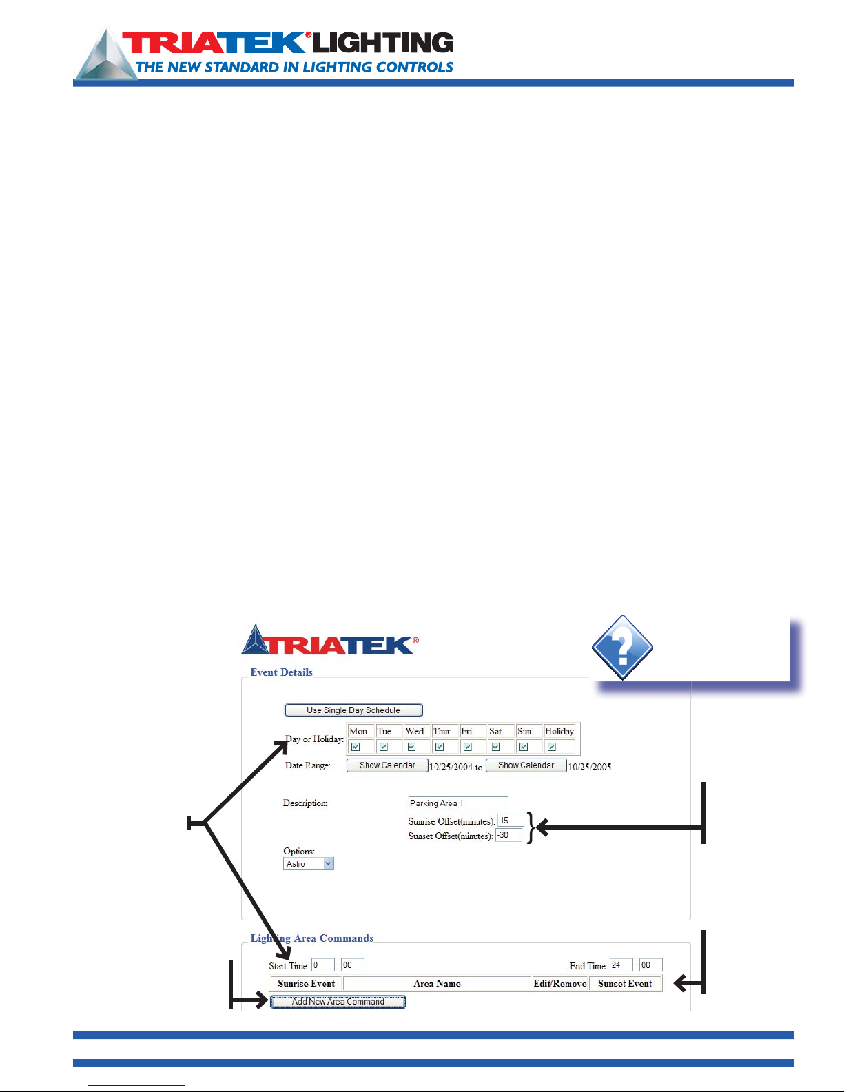
Select the “Astro” option to schedule lighting based on sunset and sunrise times. When creating a schedule with the Astro
option, the user must enter the offsets from sunrise and sunset on this page and make sure that the proper geographical
coordinates and Timezone are entered on the Set Internal Clock section of the System Setup page.
To use the Astro option:
• Go to Main Menu Add Scheduled Event Options (in Event Details Section) Astro
• In the Sunrise Offset box enter the time in minutes to offset the event from actual sunrise time.
For example: If actual sunrise time is 6:05 am, and an offset time of 15 minutes is entered, the scheduled event will
happen at 6:20 am.
• In the Sunset Offset box enter the time in minutes to offset the event from actual sunset time.
For example: If actual sunset time is 7:50 pm, and an offset time of –20 minutes is entered, the scheduled event will
happen at 7:30 p.m.
• In the Lighting Area Commands section on the same page, enter the start and end times. You may enter 0 and 24 for no
restrictions or enter start and end times to limit the scope of when the Astro events are allowed to take place.
• Select Add New Area Command
• Under Area Name, select
• Under Sunrise Event, select what state the group should go to when the Sunrise Event takes place: On, Off, or Do
Nothing.
• Under Sunset Event, select what state the group should go to when the Sunset Event takes place: On, Off, or Do
Nothing.
• Click the Save button at the bottom of the page to save these settings in the BASnet LigthtView.
Edit, and then from pull-down box select a predefi ned Area.
Go to: System Setup Set Internal Clock and verify or enter the geographical coordinates for your location. If you do not
know your coordinates, you may go to www.TRIATEKlighting.com and obtain coordinate information for your Area. See
section, Setting the Internal Clock, regarding entry of coordinates.
Hint:
Remember to click
“Save” prior to closing
browser window.
Add or subtract
offset here to
Event days & times
Select what the action
to perform when the
sunrise event occurs
the sunrise and
sunset event times
Select what the
action to perform
when the sunset
event occurs
1025 Cobb Place Blvd. Suite 100 Kennesaw, GA 30144 • 800-241-9173 • www.TRIATEKlighting.com
Page 20 of 4105/26/2005
Page 21
BASnet LightView User’s Guide
Programming the BASnet LightView
Lighting Area Commands
Note: Before continuing all areas should have already been defined. Without first defining the areas, no areas can be
added to the Schedule. See “
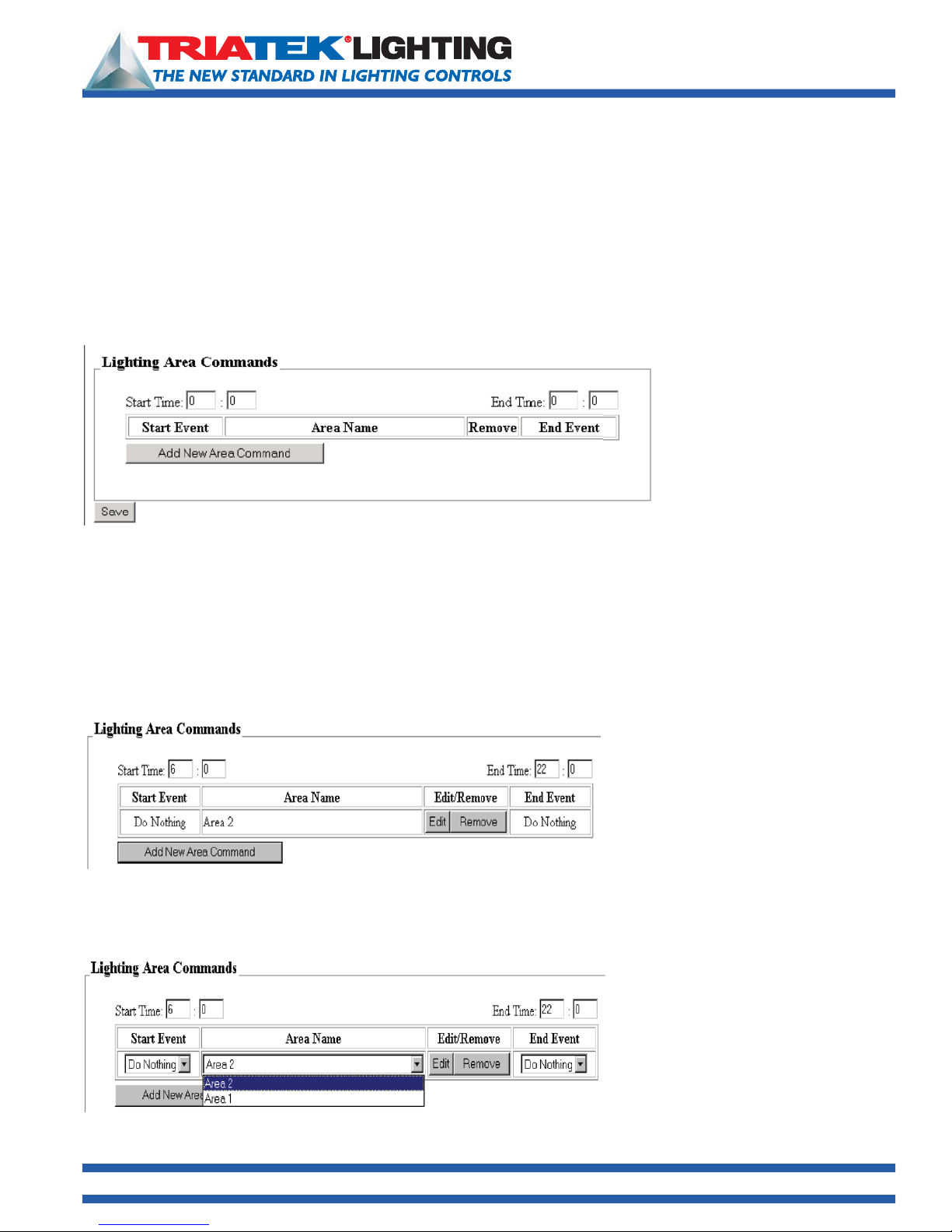
Within the ‘Lighting Area Command’ box areas are assigned to a schedule. This section contains text boxes for entering
the start time and end time for the schedule, an ‘
area selection, along with start and end action selection. A ‘Remove’ button is also included. This section of the Add Event
page is shown below: Assigning Start and End Times
In military time standard, midnight is called “twenty-four hundred hours.” Normal computer processing with military time
uses 00:00 for midnight and not 24:00. A single event’s start and end time cannot be spread over 2 days. Start and end
actions occur in the same day, and their repetition on following days is set in the Event Details box. Midnight in BLV will be
represented as 00:00. To enter the start and end times for the schedule simply click inside the test boxes and enter the
times. To create a continuous 24-hour schedule window, enter 00:00 as Start Time and 24:00 as End Time.
Creating Areas” beginning on page 14 for instructions on how to define areas.
Add New Area Command’ button, that includes text boxes for predefined
Assigning Start and End Times
The Lighting Area Commands box
first displays the start and end time
text boxes. The start and end time
for all the areas in a schedule will
be entered here. Time must be
entered as military time. The user
should note that in military time the
first hour of the day is midnight.
Adding New Areas to the Schedule
Next, in the Lighting Area Commands section, the ‘
Click the ‘Add New Area Command’ button to add a new area to the schedule.
To assign a different area to configure, and to assign start and end events click the Edit/Remove button. Text boxes will appear
that allow the user to change the start and end events and area will appear.
To change the area to confi gure for the schedule, click the arrow of the text box and select the area:
Add New Area Command’ button is used to add areas to the schedule.
A new row with area name, start and end
event headings will appear, along with
an edit/remove button. By default when the
Add New Area Command button is
clicked, the last area created will appear first
with DO NOTHING assigned for start and
end events.
1025 Cobb Place Blvd. Suite 100 Kennesaw, GA 30144 • 800-241-9173 • www.TRIATEKlighting.com
Page 21 of 4105/26/2005
Page 22
BASnet LightView User’s Guide
Programming the BASnet LightView
Lighting Area Commands (continued)
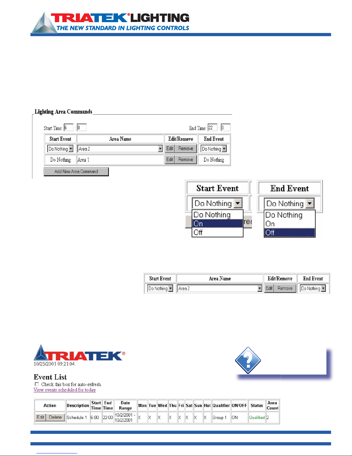
Once an area is selected to add to the schedule, it can not be selected again within the same schedule because one area
cannot be controlled twice in one schedule.
This can be verified by adding another area to the schedule:
In the working example shown through
the snap shots of this User’s Guide,
only two areas have been created.
Therefore when the Add New Area
Command button is clicked and the
area name is selected, only one area is
shown in the text box:
To assign start and end events to an area click the edit
button. The start and end events for an area are selected in
the same manner as the area name under the “
and “End Event” headings. Start and End events both have
three possible actions to execute: ON, OFF, or DO NOTHING.
Select one of the actions for the start and end event of the
selected area. See display to the right for selections.
Start Event”
Note: DO NOTHING is a unique feature because most systems require either an ON or OFF command. However, the user
may desire, for example, that switches turn lights ON in the morning and the schedule turn the lights OFF in the evening. To
accomplish this one would assign the ‘DO NOTHING’ action in the morning and OFF action in the evening.
Areas can be removed from the schedule
simply by clicking the remove button.
More areas can now be added to the current schedule or the current schedule can be saved, and a new schedule can
be created to add any remaining areas. To save the schedule without adding anymore areas click the ‘
below the Lighting Area Command box. New schedules can be created following the preceding steps.
Viewing All Schedules
Saving the current schedule brings the user to the Event List page:
Hint:
Clicking the auto-refresh
checkbox will update this
list every 10 seconds.
Save’ button just
1025 Cobb Place Blvd. Suite 100 Kennesaw, GA 30144 • 800-241-9173 • www.TRIATEKlighting.com
Page 22 of 4105/26/2005
Page 23
BASnet LightView User’s Guide
Programming the BASnet LightView
Viewing Schedules
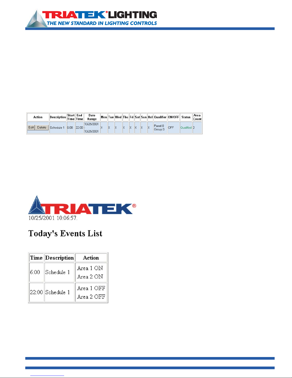
The event list displays all information pertinent to the Schedule only. No detailed information is given about groups and
areas. Only the number of areas employed in each schedule is given. Notice under the ‘Action’ heading there are ‘
and ‘delete’ buttons. The edit button allows each schedule to be edited, and the delete button deletes the Schedule. The
start and end times are also displayed along with the days of the week the events are scheduled to occur. As a part of the
days a holiday box is also shown. The event list also shows whether or not this schedule is qualified to execute. The group
used as the qualifi er is also given. The event list displays ‘
schedule is “on schedule” to execute, its entire row of information will be highlighted blue.
Once the areas in the schedule have executed, another schedule will be highlighted to show that it is the next to execute.
Once all schedules for the day have executed the fi rst schedule of the next day will be highlighted again.
Event List page also contains a link to the ‘Today’s Event List’ page. The Event List shows all created schedules; Today’s
Event List shows schedules for the current day.
Qualified’ in green and ‘Not qualified’ in red. In addition, when a
Sample “on schedule” to
execute event.
edit’
Viewing Today’s Schedules
All events scheduled for the current day are listed in ‘
Events List
This page lists current schedules, the times they execute and the
action occurring at that time. The actions display the areas for the
schedule and whether that schedule is ON, or OFF. Today’s events
are events that either have occurred or will occur.
If no events are scheduled for the current day they will not be
listed.
’ page:
Today’s
1025 Cobb Place Blvd. Suite 100 Kennesaw, GA 30144 • 800-241-9173 • www.TRIATEKlighting.com
Page 23 of 4105/26/2005
Page 24
BASnet LightView User’s Guide
Programming the BASnet LightView
Monitoring and Overriding Areas and Groups
The TRIATEK Lighting BASnet LightView enables the user to
monitor and override the current ON/OFF status of all areas and
groups scheduled in the system.
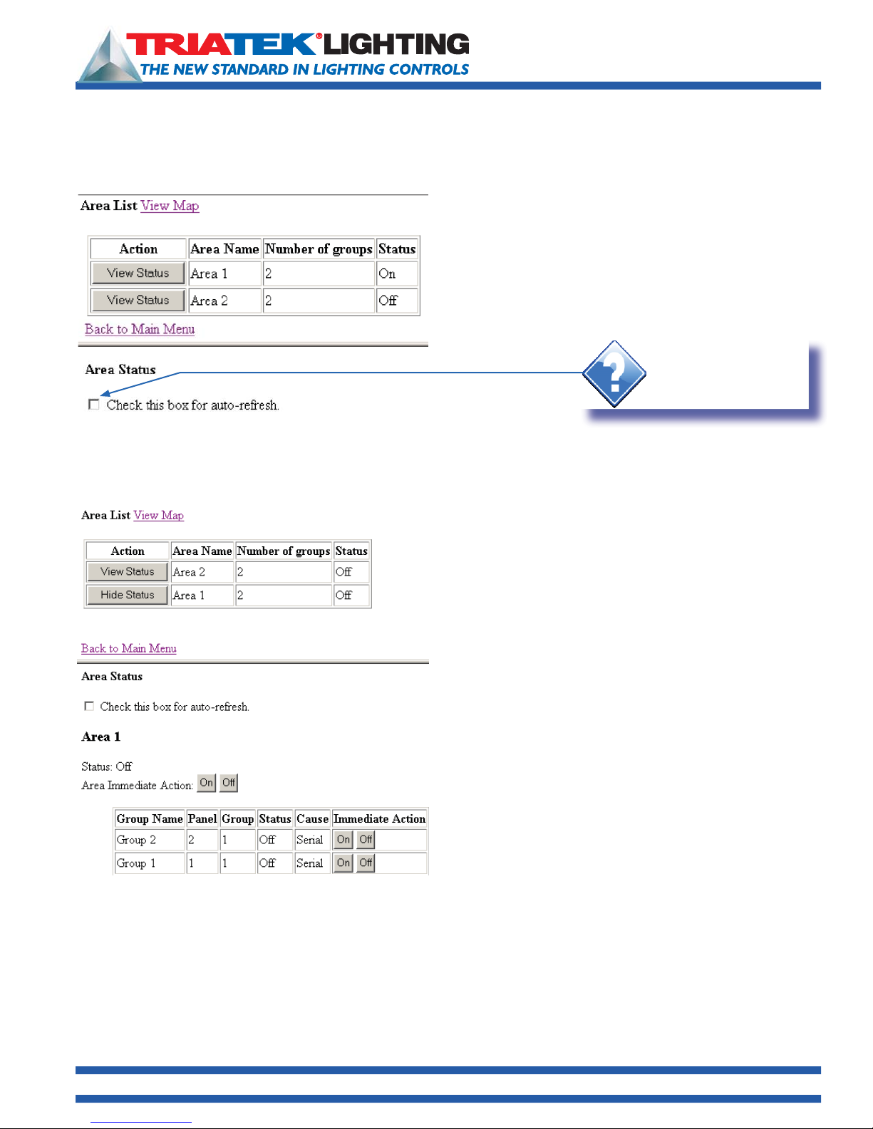
The ‘
Area and Group Status’ page shown below is used for this
purpose. The page can be reached from the ‘Area and Group
Status’ link in the main menu.
Hint:
Clicking the
checkbox will update this
list every 10 seconds.
The page utilizes a frame layout divided into two sections:
Area List at the top and Area Status at the bottom. The top section provides a list of areas with the number of groups
in each area and the ON/OFF status of each area. Detailed information for the groups in the area and immediate action
buttons or manual override buttons for the areas and groups can be accessed via the Action button. Each Action button
when clicked shows the detailed information for an area and all groups in that area in the bottom section of the page.
auto-refresh
The Action button shows hide status when the status is
displayed in the bottom section, and ‘View Status’ when no
details are shown.
Area Status fi rst provides control of the auto refresh similar
to the Event List. See “Event List” for an explanation of this
feature. This section then displays the Area description, and its
current status below it.
Below status, ON and OFF buttons are provided to send an
immediate command to the entire area. When either ON or
OFF commands are executed for the area the page will update
and its status will display the current state. The states for each
group in the area will also be updated. Their updated state is
displayed in the status column heading.
Immediate ON/OFF commands can also be executed for each
group. Their status will update accordingly.
Using the ON or OFF buttons in the Area Status section will
switch the associated relays to the ON or OFF state and hold
them in that state until the next scheduled action for that group executes, or a switch input commands the group to a
different state. If no scheduled or switch action is given, then no change will occur.
1025 Cobb Place Blvd. Suite 100 Kennesaw, GA 30144 • 800-241-9173 • www.TRIATEKlighting.com
Page 24 of 4105/26/2005
Page 25
BASnet LightView User’s Guide
Programming the BASnet LightView
Viewing Cause Data
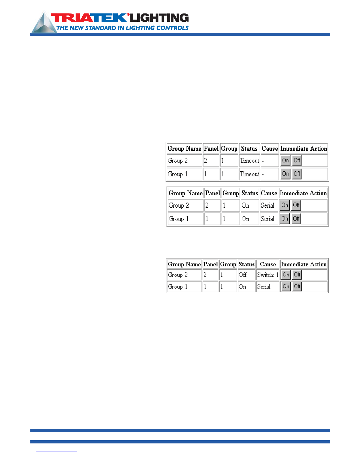
The group detail information of the Area Status frame also has a “Cause” heading. Cause data reports what caused the
lighting groups to be in their current status. Cause data can prove to be helpful information when unplanned or unexpected
lighting events occur in a building. For example, if lights were expected to be in a certain state at certain point in time,
the user can determine the source of the event that caused a group to be in that state. The cause data should be read in
conjunction with the status data. There are three possible data values that can be reported as “Cause”. They include: “-”,
“Serial”, and “Switch”. BLV sends and receives signals to and from the lighting panels via an RS-485 twisted pair network.
When this connection is broken, BLV will be unable to send and receive signal commands to and from the lighting panel.
When the connection is breached the status data will read “Timeout”, and the cause data will read “-”; the “-” indicates
there is no connection. The example shown directly below displays the Cause report generated from disconnecting the
RS-485 cable from the BLV module:
Any signals that originate with the BLV module,
including schedule commands and manual override
button commands, are included in the “Serial” cause.
Example Cause reports for a Timeout and an
immediate ON action to an area can be viewed to the
right.
Lighting panel control boards may receive switch
inputs. Switch inputs to the lighting panels generate
lighting events by any kind of lighting switch in a
building.
A switch input must be assigned to a group in order for BLV to track its event. Any switch events from inputs that are
included in groups in BLV will generate a “Switch” cause. An example of a switch input event on Group 2 is displayed below:
Notice the added number to the “Switch” report.
The number displays the number of the switch input
through which the event was executed. TRIATEK
Lighting Panel Controller boards carry up to either
16 or 24 switch inputs depending on the model. See
TRIATEK “LP Controller Users Guide” for more information. The “Switch” cause will always be reported in the form “Switch:
N”, where N is the switch input number on the TRIATEK LP Controller.
Viewing Graphics
The LightView Browser also enables uploading and viewing a graphical image. With this feature the user has on-board
access to any graphical display of the building’s lighting architecture. The map used for this purpose should be in “Portable
Network Graphics” (.png) format. The maximum size of the file is 20KB. PNG files can be produced by converting
AutoCAD and other graphical software image type files. Most software packages like the aforementioned that produce
the graphics can also convert them. Macromedia® Fireworks® Software may prove especially useful because it not only
converts images to the PNG format, but it also creates the PNG file format. When images are converted to the PNG format
the image size is reduced considerably. The example graphic shown below was originally a 867MB CAD file, that when
converted became 5.5KB png format graphic.
Refer to Upload Map under System Setup to learn how to upload the graphic. To view an uploaded graphic, click ‘View
Map’ on the ‘Area and Group Status’ page. A separate Internet Explorer window will appear to display the graphic.
1025 Cobb Place Blvd. Suite 100 Kennesaw, GA 30144 • 800-241-9173 • www.TRIATEKlighting.com
Page 25 of 4105/26/2005
Page 26
BASnet LightView User’s Guide
Programming the BASnet LightView
Viewing Graphics (continued)
In practice, the graphic used by the programmer will have more meaningful information, showing representations of the
lighting areas including their component lighting panels and groups and their status.
After the graphic is uploaded and viewed once in a login session, it will no longer need to be uploaded to be viewed again.
After viewing the map and closing the window it is displayed in, the map can be reviewed by clicking ‘View Map’ again.
The map will automatically display without uploading in consecutive viewings.
Maps can only be uploaded and viewed one map at a time. To view an addtional map, the procedure is the same.
However, uploading a new map will replace the current map loaded into the system.
Creating Holidays
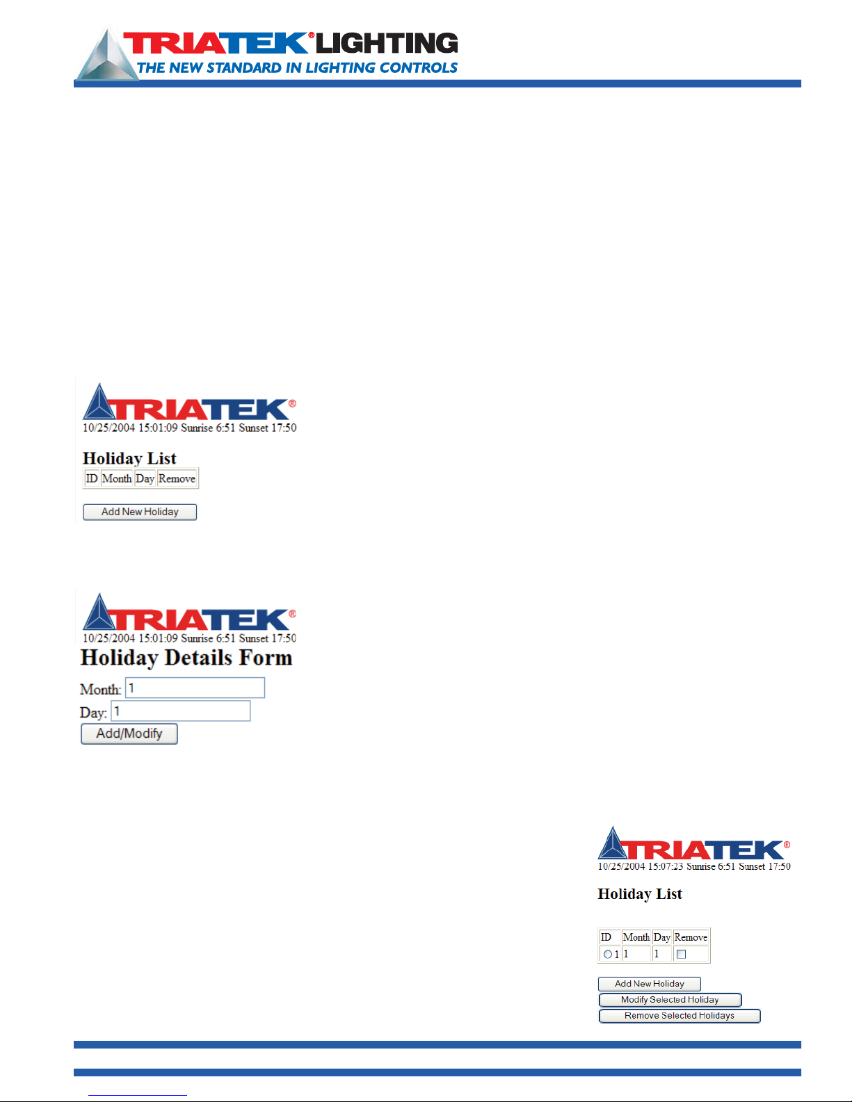
Creating a holiday in BASnet LightView tells the system not to execute scheduled
events on that day. The system can hold a maximum of 30 holidays. Holiday’s are
programmed from the ‘Holiday List’ page. To program holidays into the system go to
the ‘Holiday’ link.
The ‘Holiday List’ page is shown to the left:
The holiday page enables addition of holidays along with editing and removal of
each holiday. To begin adding holiday click the ‘Add New Holiday’ Button.
This will then cause the Holiday Details Form page to display (left):
Enter the month and day in their respective boxes and click the ‘Add/Modify’
button. This will then produce an updated Holiday List page with the new Holiday
and separate ‘Modify Selected Holidays’ and ‘Remove Selected Holidays’ buttons
added to the page.
To modify a holiday, fi rst click inside the circle under the “ID” heading for the holiday.
To remove a holiday from the list, click inside the box included under the “Remove”
heading. The selected holiday is then modifi ed or removed by clicking the ‘Modify...’
or ‘Remove...’ button.
To add a new holiday to the list, click the ‘Add New Holiday button’ and repeat the
preceding steps. To modify, click the modify button. This will bring up the ‘Holiday
Details Form’ again. Edit the holiday via the text boxes and click ‘Add/Modify’.
1025 Cobb Place Blvd. Suite 100 Kennesaw, GA 30144 • 800-241-9173 • www.TRIATEKlighting.com
Page 26 of 4105/26/2005
Page 27
Programming the BASnet LightView
Viewing System Logs
BASnet LightView User’s Guide
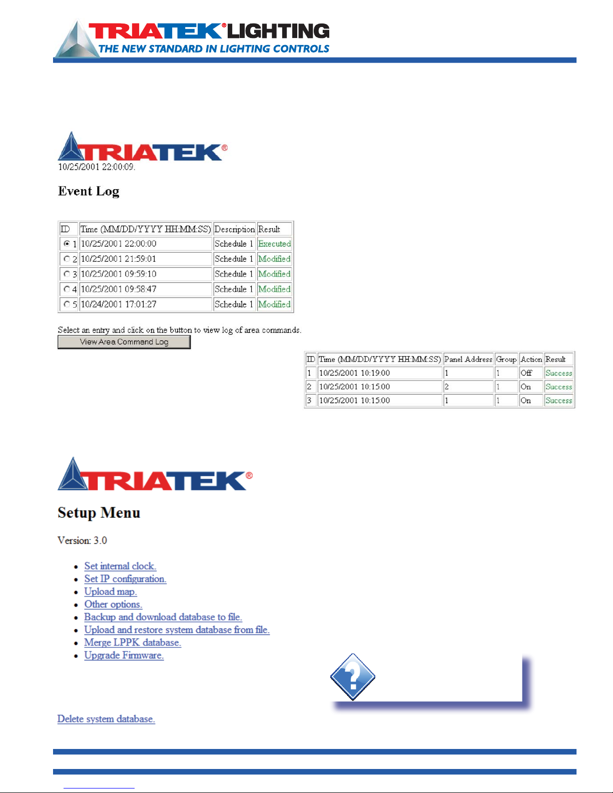
Any user modifications or command actions to areas and
groups will be recorded in the “Event Log” page. This page
lists all schedules, the time and date occurred with them and
the result of that action. Results either can be “executed” or
“modified. The page holds a maximum of 30 event logs. After
30 logs are displayed, new logs begin to replace old logs.
Below the event logs is a ‘View Lighting Area Command
Log’ button. This option enables viewing whether any action
commands to groups failed or succeeded.
Command logs can be viewed for a specifi c schedule event
log only. To view the log commands for a specifi c schedule log
select one of the schedule ID’s and then click the ‘View Area
Command Log’ button. The ‘Lighting Area Command Log’
page will display.
Logs that represent only modifi cation to areas and not
action commands will not have a command log entry.
The ‘Lighting Area Command Log’ page will display
the date, time, panel address, group number, action
performed and whether that action succeeded or failed.
The Lighting Area Command Log page holds 100 logs; its logs are replaced in the same manner as the event logs.
System Setup
The System Setup page is provided in the browser
(1) to make low level confi guration settings without having to use the
serial interface,
(2) for uploading graphics, and
(3) for performing backup and restoration of data.
Low level confi guration settings include setting the internal clock and
changing network settings.
System Setup page is shown (left):
1025 Cobb Place Blvd. Suite 100 Kennesaw, GA 30144 • 800-241-9173 • www.TRIATEKlighting.com
Hint:
Use the
option only as a last resort.
Delete system database
Page 27 of 4105/26/2005
Page 28

BASnet LightView User’s Guide
Programming the BASnet LightView
Setting Coordinates and the Internal Clock
Enter the current mm, dd and yyyy. The ability to set the internal clock is most useful for testing the operation of the
schedules, and currently the only way to stop all schedules at once is to change the time on the internal clock. Click the
Set Internal Clock’ link to enter time and date settings. All time in BLV is expressed in military time. Note: Midnight in
‘
military time is not “24:00”. Its is 00:00. See discussion of military time in the section, “
Enter the local coordinates for Latitude, Longitude and Timezone. The proper
local coordinates are necessary for the Astro feature to function properly. The
format for coordinates is Degrees.decimal (example 84.29). Latitudes above the
equator are positive and longitudes west of Greenwich are negative. A look-up
table for co-ordinates of U.S. Cities is provided at the end of this document and
also on the website at www.TRIATEKlighting.com
• In the Latitude box, enter the latitude for your location in degrees. Latitudes
north of the equator are positive.
• In the Longitude box, enter the longitude for your location in degrees.
Longitudes north of the equator are positive.
• Enter the Timezone as the Greenwich Mean Time (GMT) offset. For example,
USA EST Timezone is –5 and PST is –8.
To add sunrise and sunset offsets for a particular event, go to section on
Adding Schedule Events, Astro Option.
• The Daylight Savings (DST) adjustment is disabled by default. Enable this
feature and schedules will execute at the correct time when Daylight Savings
is in ef In the Longitude box, enter the longitude for your location in degrees
Longitudes west of Greenwich, England are negative.
• In the Timezone box, enter your local timezone. The timezone is the Greenwich Mean Time (GMT) offset. For example,
USA EST timezone is –5 and PST is –8 (GMT) offset.
• Click the Update Time button at the bottom of the page to save these settings in LightView.
Assigning Start and End Times”
Setting IP Configuration
TRIATEK ships the BLV module with default network settings.
If the browser must be moved to a different network or subnet,
the settings can be changed in System Setup. Select the ‘Set
IP Confi guration
for browser IP, Subnet mask, Gateway, and the Domain Name
Server (DNS). After all addresses have been entered click ‘update
confi guration’. The ‘Set IP Confi guration’ page is shown to the right:
It should be noted that once the confi guration changes the old IP
address for the browser can no longer be used to reach BASnet
Lightview. The URL of the new IP address must be used. This note
is included as a warning on the “Set IP Confi guration” page.
’ link, and enter the new network addresses
1025 Cobb Place Blvd. Suite 100 Kennesaw, GA 30144 • 800-241-9173 • www.TRIATEKlighting.com
Page 28 of 4105/26/2005
Page 29
BASnet LightView User’s Guide
Programming the BASnet LightView
Uploading Graphics
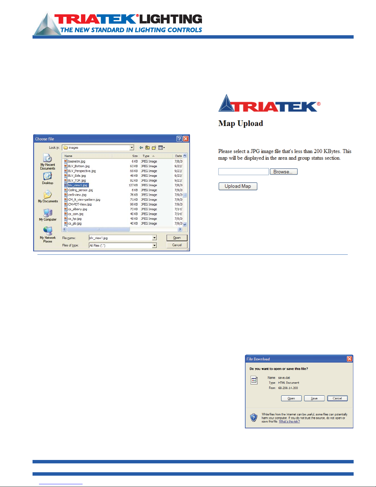
Graphic fi les can also be uploaded into the BLV system, from the ‘Map Upload’ page. This page can be reached from
System Setup by clicking the ‘Upload Map’ link. For a detailed
discussion on the use, size, and type of the graphic, see “Viewing
Graphics
type PNG and should be no more than 20KB in size. To up load the
graphic click on ‘View Map’ link. The ‘Map Upload’ page will appear:
” on page 25. Graphics to upload into BLV should be of
If you know the path of the fi le it can be entered manually into
the text box. To choose the fi le from a location on the local
machine or network, click the Choose button. Then locate
the PNG fi le to upload. Click “Open” to upload the fi le.
Once the fi le has been uploaded, the fi le can be viewed from
the ‘Area and Group Status’ page. For instructions on how to
view the map, see “Viewing Graphics” on page 25
Programming the BASnet LightView
Backup and Restoration of Data
The BASnet LightView also provides backup and restore features found in System Setup. All data saved via the browser
is stored in the Random Access Memory (RAM) on the main board, and it remains in RAM by virtue of the battery
attached underneath the module. Therefore even on a power loss to the module the data should remain intact. The main
purpose of the backup feature is to have data on a fi le that is readily accessible when data needs to be restored without
having to reprogram the module. Although this fi le initially resides in RAM on the module board it can be moved to a local
PC or to any machine on an accessible network using the backup and download function, and then it can be moved
back again to the module using the upload and restore function. The procedures for backing up database to fi le and
restoring the database from fi le is described below.
Backing up data
To back up all confi guration data select ‘Backup and download database to
fi le’ link from System Setup. Selecting this option will store a fi le named ‘save.
dat’, on the module board in RAM. Once the link is selected and the data has
been written to fi le, a fi le download window will appear that prompts the user
to either open the fi le from its current location or to save this fi le to disk.
The fi le can be opened, but it is encoded for use by BLV and not the user.
Interpreting the construction of this fi le is outside the scope of this user guide;
however, if the user would like to learn its structure it would then be possible to create this fi le without having to reenter
data into BLV. This could prove useful if the fi le is ever deleted without being backed up.
1025 Cobb Place Blvd. Suite 100 Kennesaw, GA 30144 • 800-241-9173 • www.TRIATEKlighting.com
Page 29 of 4105/26/2005
Page 30
Programming the BASnet LightView
Backing up data (continued)
BASnet LightView User’s Guide
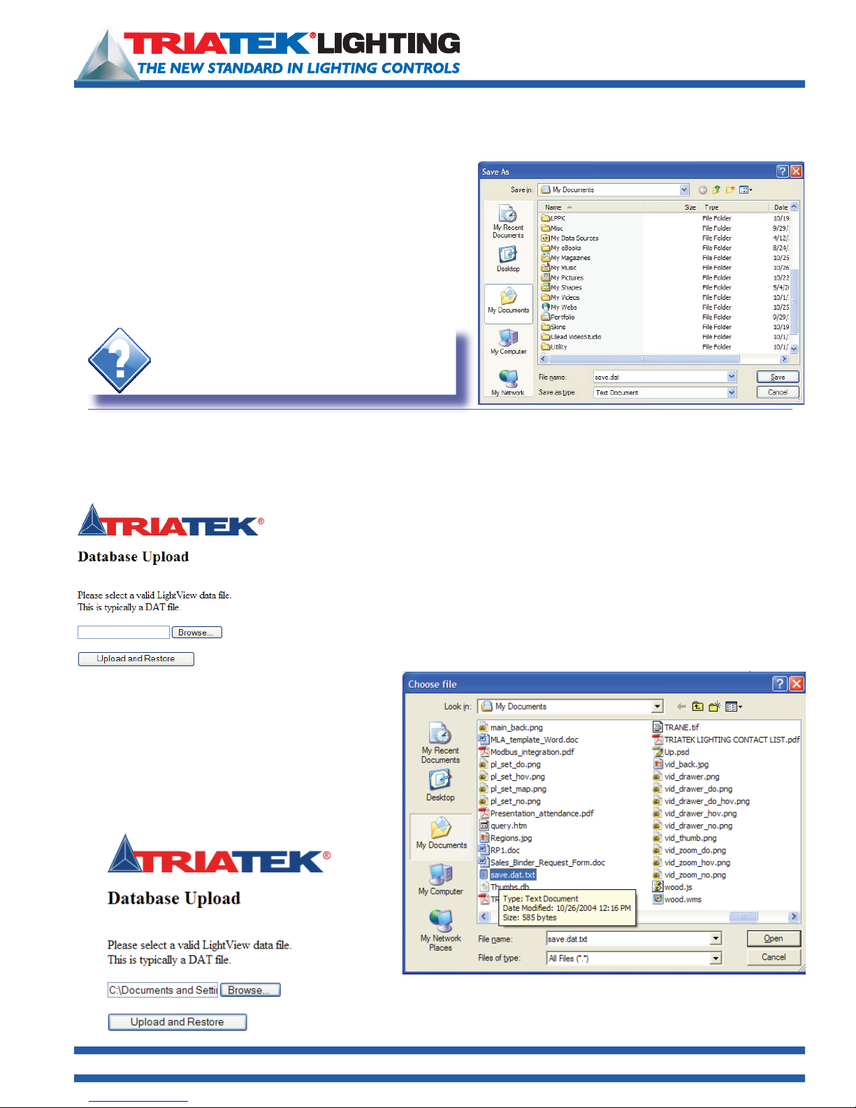
To download the fi le click, “
‘OK’ button. A ‘Save As’ window will then appear.
(Screen appearance will vary by operating system version)
Select the destination folder to save “save.dat”. In the “
as type” fi eld chose “Text Document” or “Text File”. Click the
“save” button. The fi le has now been backed up to the specifi ed
location.
Hint:
When in doubt as to where to save a file, save it
in the default directory provided.
Restoring data
Only when data has been backed up to fi le can the user restore upload and restore the database. Upload and restore
performs essentially the opposite functions as backup and download.
Save this fi le to disk”, and click the
Save
To upload and restore the database, from System Setup click the “Upload and restore
system database from fi le” link. Instead of a window appearing here, the link brings the
user to another page in the system, the “Database Upload” page.
If the user knows the path of the fi le, it can be entered directly into the text box, or
the user can browse their computer or network and select the fi le. To browse for
the fi le, click the “Browse...” button. A window titled, “Choose fi le” will appear. This
window is similar to the ‘Save As’ window used with backup and download; instead
of saving here the fi le is being chosen to upload.
Locate the fi le, select it and click “
(right):
The fi le with it’s path will appear in the text box of the
database upload page.
Now click the “
bring the user back to the Event List page, where the
uploaded and restored data will be displayed.
Upload and Restore” button. This will
1025 Cobb Place Blvd. Suite 100 Kennesaw, GA 30144 • 800-241-9173 • www.TRIATEKlighting.com
Open” as shown
Page 30 of 4105/26/2005
Page 31
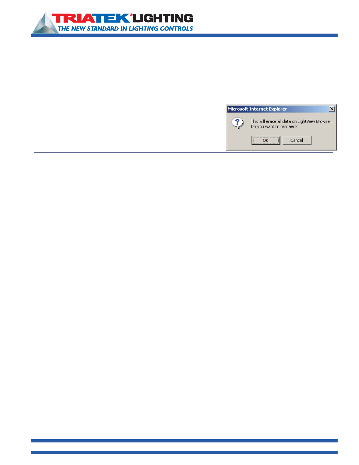
BASnet LightView User’s Guide
Programming the BASnet LightView
Deleting the System Database
TThe fi nal option in System Setup is deleting the system database. Deleting the database essentially clears the save.
dat fi le. The fi le still exists in system memory, but once deleted the fi le will contain no data. When the link is clicked a
confi rmation window will appear.
To delete the database click the ‘Delete System Database’ link on the
System Setup page. Click “OK” in the confi rmation window. The page will
then reset itself to the same form as a “bare” installation. This implies that
not only will group, area and event information be cleared, but so will all log
information. It is a good idea to always ensure there is a backup copy of the
save.dat fi le should the fi le be deleted accidentally.
Telephone Override with BASnet LightView
Overview
BASnet LightView is factory confi gured to work with TRIATEK’s TI-4500-0-Net telephone override interface. With this
option, the TI-4500-0-Net will have a unique address and sit on the RS-485 network just like a TRIATEK lighting panel
as shown below. LightView can connect to as many as 4 TI-4500-0-Net units on the same network. Addresses 252,
253, 254, 255 are reserved in LightView for this purpose. Mapping the TI Outputs to the Panel Groups in LightView It
is important to remember that a user will call the TI and enter a pre-set User ID number corresponding to the lighting
circuit for his space in the building. For this to happen, the following associations must be mapped into the system by the
installer:
1.) At each lighting panel, relays or breakers are assigned to the appropriate lighting Panel Group using LPPK.
2.) Each lighting panel is assigned a unique address on the RS-485 network using LPPK or the panel controller’s push
buttons.
3.) In the LightView module, the Panel Groups must be defi ned including the panel address 1-251, and the Panel Group.
This is done using MS Internet Explorer browser as explained in earlier sections of this BLV User Guide. The Panel
Groups are the same ones previously defi ned above, using LPPK.
Assigning the User a Telephone Override Code
Before a user’s ID# can be assigned, the installer or administrator must determine which Panel Address and Panel Group
contains the user’s lighting circuit. This number is fi xed since it is completely determined by the location of the lighting
circuit relay in its uniquely addressed panel. The installer or administrator can then use the circuit location to look up the
ID number in a special table provided by TRIATEK or calculate it by special equation provided by TRIATEK. The equation
is:
ID = [(Panel Address #) x 64] + Panel Group #.
The look-up table is provided with TI-4500-0-Net for BLV or can be found at the TRIATEK Lighting web site. Go to www.
triateklighting.com then select in succession these buttons/links:
Products BASnet LightView Module TI/BASnet ID Table.
Although the ID is completely fi xed, the option to protect access to the ID by a password can be enabled in the TI-4500.
1025 Cobb Place Blvd. Suite 100 Kennesaw, GA 30144 • 800-241-9173 • www.TRIATEKlighting.com
Page 31 of 4105/26/2005
Page 32

BASnet LightView User’s Guide
Telephone Override with BASnet LightView
Range of ID Numbers
The User ID numbers in the TI-4500-0-Net are preset to the TRIATEK lighting panel groups in LightView. The range of
Panel Groups controlled by TI/BLV is Panel address 1 Group1 through Panel address 127 Group 60. This range of 7,620
panel groups can be accessed by one TI module or spread over as many as 4 TI modules on the same RS-485 network
connected to one BLV. However, one BLV can only control up to 1000 Panel Groups. Thus, although only 1000 Panel
Groups can be defi ned by BLV, these 1000 groups may be defi ned within a range of 7,620 possible Panel Groups.
Steps to Set-up TI-4500-Net with LightView
In order to set up the override system, the following simple steps should be considered. In these steps, 3 areas are
confi gured: the TI-4500-Net, the lighting panels and the LightView module. For this application of TI-4500, insure that the
Output Hold Time in the TI Master Commands be not less than 20 seconds.
1. Refer to TI-4500 Installation Guide for the following:
a. Wiring power supply to TI-4500.
b. Battery Backup
c. Telephone Connections
d. LED Indications
e. Master Operation
(1) Output hold time must not be less than 20 sec for this application.
f. Binary outputs mentioned in the TI install guide are pre-wired into an I/O module in the TI enclosure for this
application (TI-4500-Net).
2. Refer to the wiring diagram below for the following:
a. Locate the network I/O module below the TI main board and connect it to the lighting panel RS-485 network. This
module is factory addressed at 252. (Three additional TI-4500-0-Net devices can be included on the network but
must be addressed 253-255.) Lighting panels on the network with TI-4500-0-Net must be addressed between
1-127 if they are to be commanded by the LightView for requests for telephone override. Other panels may be
addressed between 1-255.
b. Connect the RS-485 twisted pair to the LightView BASnet RS-485 port A.
3. In order for the TI-4500 to interface with the BASnet LightView browser, Lighting panel Groups and Areas must be
defi ned and assigned just as they would be in a BASnet LightView system without a TI interface. Refer to earlier
sections of the BASnet LightView User’s Guide.
4. Refer to TI/BASnet ID Tables to identify TI user ID numbers (see TI Master Operation in 1 above).
Otherwise use ID# = [(Panel Address) x 64] + Panel Group Number
a. In order to assign a particular area of lighting to the Telephone Override, the administrator must determine which
lighting panel address and panel group number the lights belong to. The lighting area to be overridden cannot be
smaller than a lighting panel group as assigned in the lighting panel program ming. (Refer to LP Controller User’s
Guide - Confi guring Outputs)
b. In addition, the lighting panel and group must also be defi ned as a “Group” in the BASnet LightView Browser.
Normally, this group is also assigned to an “Area” also defi ned in LightView.
c. The User ID referred to by the TI Install and Setup Guide actually refers to a particular building space. This number is
completely determined by the lighting panel network address and group number. The group number identifi es the
relay and circuit within that panel that is supplying the lights with power.
d. Once this number is determined, it merely needs to be assigned to the appropriate user. The system does the rest.
The user can then call the TI-4500, answer the voice prompts and obtain the desired override On of lights after
normal scheduled hours.
5. General Operation:
a. Passwords may be enabled or disabled as explained in the TI-4500 Installation Guide - Master Operation
b. Overrides may be requested in increments of 1 hour for 1 to 6 hours. A “7”will cancel the present override.
c. The system uses “Last Command Rules” logic in relation to Light Schedules in BASnet and local wall switch
commands. If an off-sweep of building lights in BASnet occurs shortly after a request of override, merely call in
again to begin a new period of telephone override.
1025 Cobb Place Blvd. Suite 100 Kennesaw, GA 30144 • 800-241-9173 • www.TRIATEKlighting.com
Page 32 of 4105/26/2005
Page 33
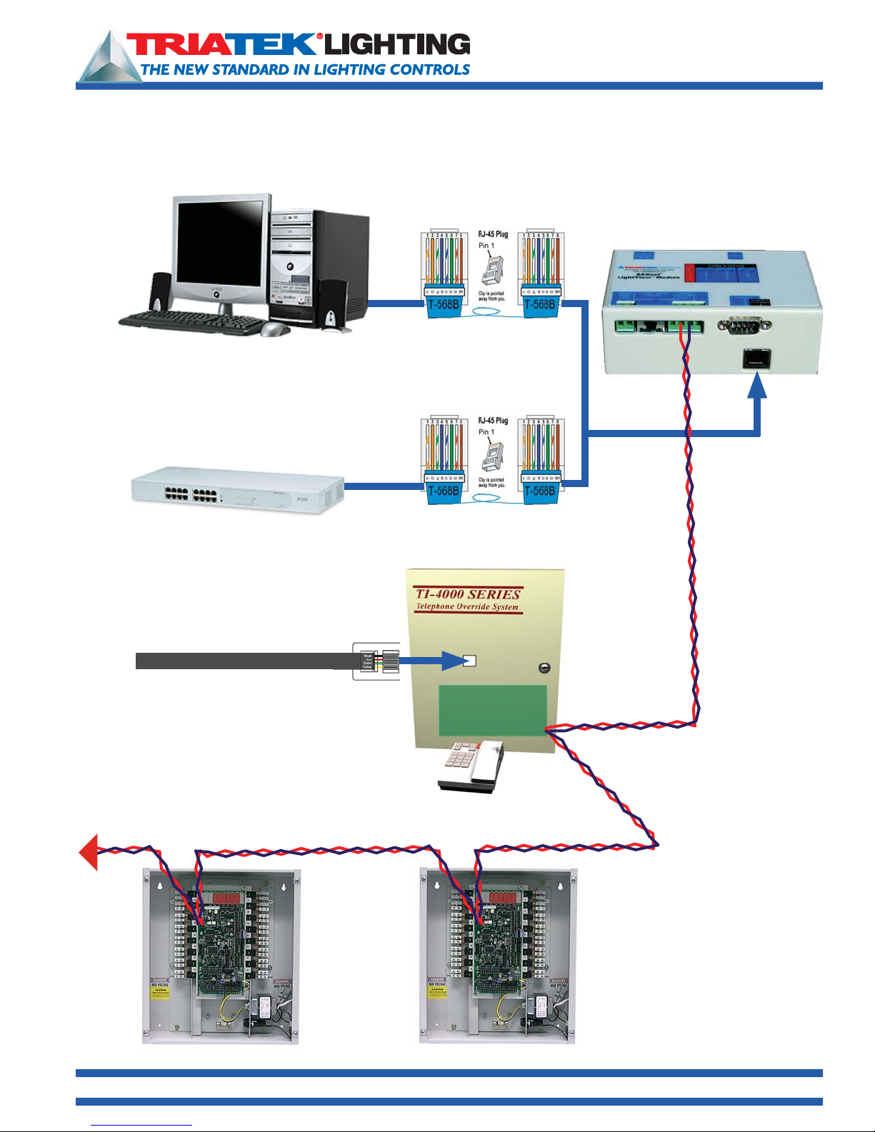
Telephone Override with BASnet LightView
Wiring Diagram - Telephone Interface with BASnet LightView
RJ-45 Crossover
Ethernet Cable
IBM Compatible PC or Laptop
RJ-45 Straight-Through
Ethernet Cable
Ethernet Hub, Router or Switch
BASnet LightView User’s Guide
CAT 5
Telephone Interface
TI-4500-NET
Address 252-255
Dedicated RJ11
Phone Line
RS-485
Address 1-251
Lighting Panel
TI-4500-Net
Lighting Main Board
Address 1-251
Lighting Panel
RS-485
1025 Cobb Place Blvd. Suite 100 Kennesaw, GA 30144 • 800-241-9173 • www.TRIATEKlighting.com
Page 33 of 4105/26/2005
Page 34
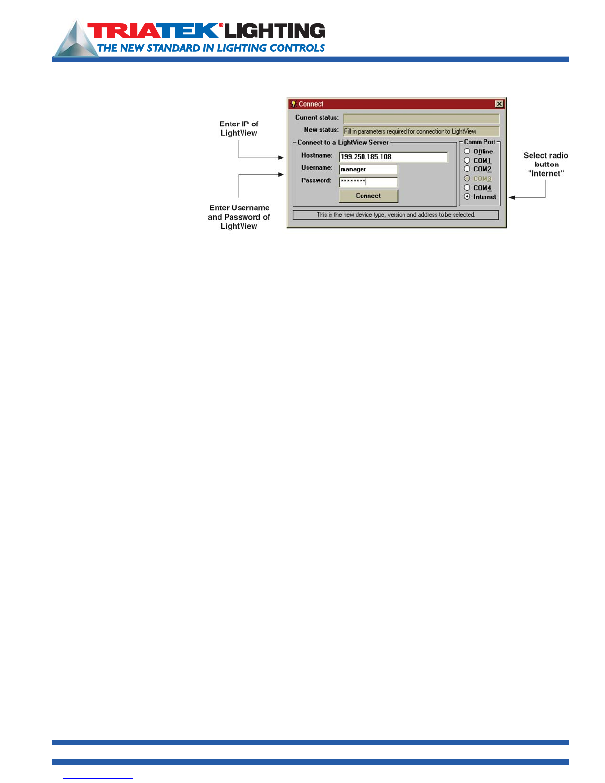
BASnet LightView User’s Guide
LPPK with BASnet LightView
BASnet LightView allows users
to program all TRIATEK panels
connected to BLV over the
Internet from any location. The
workstation must be running
version LPPK. When using LPPK
with LightView, scheduled lighting
events will still take place. During
LPPK programming activities via
LightView, response times on
LPPK may be noticeably slower,
because LightView is being shared.
To use LPPK via BASnet LightView:
• Have the PC or Laptop connected to LightView as described in section “Connecting to BLV”.
• Start LPPK and on connect screen, select radio button “Internet”.
• Still on the Connect screen, enter the IP address for LightView in the box “Hostname”
• Enter the Username and Password
• Click the Connect button
• LightView will authenticate the connection
• Continue normal programming with LPPK.
1025 Cobb Place Blvd. Suite 100 Kennesaw, GA 30144 • 800-241-9173 • www.TRIATEKlighting.com
Page 34 of 4105/26/2005
Page 35

BASnet LightView User’s Guide
BASnet LightView Programming Worksheets
BASnet Programming Worksheet - Area and Group Assignments
Area Description (23 Character limit) Group Desctiption (23 Character limit) Panel # 1-255 Group # 1-60
1025 Cobb Place Blvd. Suite 100 Kennesaw, GA 30144 • 800-241-9173 • www.TRIATEKlighting.com
Page 35 of 4105/26/2005
Page 36

BASnet LightView Programming Worksheets
BASnet Programming Worksheet - Holidays
Holiday Month Day
BASnet LightView User’s Guide
1025 Cobb Place Blvd. Suite 100 Kennesaw, GA 30144 • 800-241-9173 • www.TRIATEKlighting.com
Page 36 of 4105/26/2005
Page 37

BASnet LightView Programming Worksheets
BASnet Programming Worksheet - Schedules
ON or OFF
Do nothing,
ON or OFF
BASnet LightView User’s Guide
Schedule Area name Day of Week Start Date End Date Start Time Start Action Stop Action
Description Scheduled Mon Tue Wed Thu Fri Sat Sun Hol mm/dd/yy mm/dd/yy hh:mm Do nothing,
1025 Cobb Place Blvd. Suite 100 Kennesaw, GA 30144 • 800-241-9173 • www.TRIATEKlighting.com
Page 37 of 4105/26/2005
Page 38

BASnet LightView User’s Guide
BASnet LightView Programming Worksheets
Latitude-Longitude (decimal and degrees/minutes/seconds) of US Cities used by permission (www.realestate3d.com)
1. Use Decimal Format
2. Add Negative sign when entering a Longitude into Lightview.
Code BASnet Lat/Lon Latitude Longitude City / State
[AUO] 32.67 85.44 32 40 11 85 26 24 Auburn, AL
[BHM] 33.57 86.75 33 34 11 86 45 0 Birmingham,AL
[ANC] 61.17 150.02 61 10 11 150 1 12 Anchorage,AK
[FAI] 64.82 147.87 64 49 11 147 52 11 Fairbanks,AK
[FLG] 35.13 111.67 35 7 48 111 40 11 Flagstaff,AZ
[PHX] 33.43 112.02 33 25 48 112 1 11 Phoenix,AZ
[LIT] 35.22 92.38 35 13 12 92 22 47 LittleRock,AR
[CRQ] 33.13 117.28 33 7 48 117 16 47 Los Angles,CA
[TVL] 38.90 120.00 38 54 0 120 0 0 San Francisco,CA
[DEN] 39.75 104.87 39 45 0 104 52 12 Denver,CO
[FCS] 38.68 104.77 38 40 48 104 46 11 FortCarson,CO
[BDR] 41.17 73.13 41 10 11 73 7 47 Bridgeport,CT
[HFD] 41.73 72.65 41 43 47 72 39 0 Hartford,CT
[DOV] 39.13 75.47 39 7 48 75 28 12 Dover,DE
[IAD] 38.95 77.46 38 57 0 77 27 35 Washington/Dulles,DC
[XMR] 28.47 80.55 28 28 11 80 33 0 CapeCanaveral,FL
[EYW] 24.55 81.75 24 32 59 81 45 0 KeyWest,FL
[ATL] 33.65 84.42 33 39 0 84 25 11 Atlanta,GA
[CSG] 32.52 84.93 32 31 12 84 55 48 Columbus,GA
[HNL] 21.35 157.93 21 21 0 157 55 47 HonoluluInt,HI
[LNY] 20.80 156.95 20 47 59 156 56 59 Lanai-Lanai,HI
[BOI] 43.57 116.22 43 34 11 116 13 12 Boise,ID
[IDA] 43.52 112.07 43 31 12 112 4 11 IdahoFalls,ID
1025 Cobb Place Blvd. Suite 100 Kennesaw, GA 30144 • 800-241-9173 • www.TRIATEKlighting.com
Page 38 of 4105/26/2005
Page 39

BASnet LightView User’s Guide
BASnet LightView Programming Worksheets
Latitude-Longitude (decimal and degrees/minutes/seconds) of US Cities used by permission (www.realestate3d.com)
1. Use Decimal Format
2. Add Negative sign when entering a Longitude into Lightview.
Code BASnet Lat/Lon Latitude Longitude City / State
[ARR] 41.77 88.32 41 46 12 88 19 11 Aurora,IL
[ORD] 41.98 87.90 41 58 47 87 54 0 Chicago/O’hare,IL
[IND] 39.73 86.27 39 43 47 86 16 11 Indianapolis,IN
[DSM] 41.53 93.65 41 31 47 93 39 0 DesMoines,IA
[DDC] 37.77 99.97 37 46 12 99 58 12 DodgeCity,KS
[TOP] 39.07 95.62 39 4 11 95 37 12 Topeka,KS
[BWG] 36.97 86.43 36 58 12 86 25 48 BowlingGreen,KY
[SDF] 38.18 85.73 38 10 48 85 43 48 Louisville,KY
[BTR] 30.53 91.15 30 31 48 91 9 0 BatonRouge,LA
[MSY] 29.98 90.25 29 58 47 90 15 0 NewOrleans,LA
[BGR] 44.80 68.82 44 47 59 68 49 11 Bangor,ME
[BHB] 44.45 68.37 44 27 0 68 22 12 BarHarbor,ME
[BAL] 39.18 76.67 39 10 48 76 40 11 Baltimore,MD
[SBY] 38.33 75.50 38 19 48 75 30 0 Salisbury,MD
[BOS] 42.37 71.03 42 22 11 71 1 47 Boston,MA
[DET] 42.42 83.02 42 25 11 83 1 11 Detroit,MI
[GRR] 42.88 85.52 42 52 48 85 31 11 GrandRapids,MI
[FRM] 43.65 94.42 43 39 0 94 25 11 Fairmont,MN
[STP] 44.93 93.05 44 55 48 93 3 0 SaintPaul,MN
[GPT] 30.40 89.07 30 23 59 89 4 11 Gulfport,MS
[TUP] 34.27 88.77 34 16 12 88 46 11 Tupelo,MS
[COU] 38.82 92.22 38 49 11 92 13 12 Columbia,MO
[MKO] 35.66 95.36 35 39 35 95 21 36 Muskogee,MO
1025 Cobb Place Blvd. Suite 100 Kennesaw, GA 30144 • 800-241-9173 • www.TRIATEKlighting.com
Page 39 of 4105/26/2005
Page 40

BASnet LightView User’s Guide
BASnet LightView Programming Worksheets
Latitude-Longitude (decimal and degrees/minutes/seconds) of US Cities used by permission (www.realestate3d.com)
1. Use Decimal Format
2. Add Negative sign when entering a Longitude into Lightview.
Code BASnet Lat/Lon Latitude Longitude City / State
[BIL] 45.80 108.53 45 47 59 108 31 47 Billings,MT
[WEY] 44.65 111.10 44 39 0 111 5 59 WYellowston,MT
[ANW] 42.58 99.98 42 34 48 99 58 48 Ainsworth,NE
[OMA] 41.30 95.90 41 17 59 95 54 0 Omaha/Eppley,NE
[RNO] 39.50 119.78 39 30 0 119 46 47 Reno,NV
[HTH] 38.55 118.63 38 32 59 118 37 47 Hawthorne,NV
[CON] 43.20 71.50 43 12 0 71 30 0 Concord,NH
[ACY] 39.45 74.57 39 27 0 74 34 11 AtlanticCity,NJ
[TTN] 40.28 74.82 40 16 47 74 49 11 Trenton,NJ
[ABQ] 35.05 106.60 35 2 59 106 35 59 Albuquerque,NM
[SVC] 32.63 108.17 32 37 48 108 10 11 SilverCity,NM
[ALB] 42.75 73.80 42 45 0 73 48 0 Albany,NY
[JFK] 40.65 73.78 40 39 0 73 46 47 NewYork/JFK,NY
[AVL] 35.43 82.55 35 25 48 82 33 0 Asheville,NC
[CLT] 35.22 80.93 35 13 12 80 55 48 Charlotte,NC
[BIS] 46.77 100.75 46 46 12 100 45 0 Bismarck,ND
[FAR] 46.90 96.80 46 54 0 96 48 0 Fargo,ND
[CAK] 40.92 81.43 40 55 11 81 25 48 Canton,OH
[CVG] 39.05 84.67 39 2 59 84 40 11 Cincinnati,OH
[OKC] 35.40 97.60 35 24 0 97 35 59 OklahomaCty,OK
[TUL] 36.20 95.90 36 12 0 95 54 0 Tulsa,OK
[PDT] 45.68 118.85 45 40 48 118 50 59 Pendleton,OR
[RDM] 44.27 121.15 44 16 12 121 9 0 Redmond,OR
1025 Cobb Place Blvd. Suite 100 Kennesaw, GA 30144 • 800-241-9173 • www.TRIATEKlighting.com
Page 40 of 4105/26/2005
Page 41

BASnet LightView User’s Guide
BASnet LightView Programming Worksheets
Latitude-Longitude (decimal and degrees/minutes/seconds) of US Cities used by permission (www.realestate3d.com)
1. Use Decimal Format
2. Add Negative sign when entering a Longitude into Lightview.
Code BASnet Lat/Lon Latitude Longitude City / State
[ABE] 40.65 75.43 40 39 0 75 25 48 Allentown,PA
[CXY] 40.22 76.85 40 13 12 76 50 59 Harrisburg,PA
[PVD] 41.73 71.43 41 43 47 71 25 48 Providence,RI
[CAE] 33.95 81.12 33 57 0 81 7 12 Columbia,SC
[SPA] 34.92 81.96 34 55 11 81 57 35 Spartanburg,SC
[ABR] 45.45 98.43 45 27 0 98 25 48 Aberdeen,SD
[FSD] 43.58 96.73 43 34 48 96 43 48 SiouxFalls,SD
[CHA] 35.03 85.20 35 1 47 85 11 59 Chattanooga,TN
[TYS] 35.82 83.98 35 49 11 83 58 48 Knoxville,TN
[AUS] 30.30 97.70 30 17 59 97 41 59 Austin,TX
[DFW] 32.90 97.03 32 54 0 97 1 47 Dallas/FW,TX
[CDC] 37.70 113.10 37 42 0 113 5 59 CedarCity,UT
[PVU] 40.22 111.72 40 13 12 111 43 12 Provo,UT
[BTV] 44.47 73.15 44 28 12 73 9 0 Burlington,VT
[LYH] 37.33 79.20 37 19 48 79 11 59 Lynchburg,VA
[RIC] 37.50 77.33 37 30 0 77 19 48 Richmond,VA
[SEA] 47.45 122.30 47 27 0 122 18 0 Seattle,WA
[TIW] 47.27 122.58 47 16 12 122 34 48 Tacoma,WA
[HTS] 38.37 82.55 38 22 11 82 33 0 Huntington,WV
[MSN] 43.13 89.33 43 7 48 89 19 48 Madison,WI
[MKE] 42.95 87.90 42 57 0 87 54 0 Milwaukee,WI
[COD] 44.52 109.02 44 31 12 109 1 11 Cody,WY
[P60] 44.55 110.42 44 32 59 110 25 11 Yellowstone,WY
1025 Cobb Place Blvd. Suite 100 Kennesaw, GA 30144 • 800-241-9173 • www.TRIATEKlighting.com
Page 41 of 4105/26/2005
 Loading...