

Page 1

Triarchy®VSG6G1C
USB Vector RF Signal Generator
Operating Manual
9248 163 Street
Surrey, BC V4N 3C9
604-637-2167
info@triarchytech.com
CW signal Analog modulation GMSK modulation 8PSK Pulse modulation
NB RF noise generator Frequency sweeping Hopping with data Mod GSM signal 4FSK
Page 1 of 27
Page 2

USB Vector RF Spectrum Analyzer Operating Manual
Copyright Notice
Copyright © 2018 Triarchy Technologies, Corp. All rights reserved.
Initial Version December 2018
Documentation version 1.0
9248 163 Street
Surrey, BC V4N 3C9
604-637-2167
info@triarchytech.com
No part of this publication may be reproduced, transmitted, transcribed, stored in a retrieval system, or translated into
any language or computer language, in any form or by any means, electronic, mechanical, magnetic, optical, chemical,
manual, or otherwise, without the prior written permission of Triarchy Technologies, Corp.
Technical Support
For technical support, please call 1-604-637-2167, send email to info@triachytech.com, or visit our website at
http://www.triarchytech.com
Page 2 of 27
Page 3

Contents
1 Introduction 4
2 Getting Started 9
3 Operations 12
4 I&Q Engine 22
9248 163 Street
Surrey, BC V4N 3C9
604-637-2167
info@triarchytech.com
1.1 VSG6G1C Product Package Overview 4
1.2 USB Device Overview 4
1.3 TSG PC Application Overview 5
1.4 Electrical Requirements 6
1.5 Product internal Option unit 8
2.1 Install PC Application 9
2.2 Uninstall PC Application 10
2.3 First Working Example 10
2.4 TSG Utility keys setting 10
3.1 Single frequency without Pulse modulation 12
3.2 Single frequency with Pulse modulation 13
3.3 Frequency Sweeping without Pulse Modulation 14
3.4 Frequency Sweeping with Pulse Modulation 14
3.5 Frequency hopping with/without Pulse Modulation 15
3.6 Analog Modulation 15
3.7 Digital Modulation with I&Q Engine 16
3.8 Phase Modulation with I&Q Engine 17
3.9 Example for GSM signal output 18
3.10 Low Band 19
3.11 Pulse modulation signal output 21
3.12 Clock selection 21
3.13 I&Q sel 21
3.14 Hardcopy Operation 21
3.15 Off Line Operation 21
3.16 Flash OFF/ON Operation 22
4.1 I&Q Engine principle 22
4.2 I&Q file configuration 23
Page 3 of 27
Page 4

1 Introduction
VSG6G1C is USB RF signal generator, it plug on PC and working with PC application, then VSG6G1C will be really
RF signal generator, the RF frequency range from 100Hz to 6.1GHz for VSG6G1C model, Amplitude output range
will be -100dBm~10dBm. VSG6G1C are will very easy to use, PC application window just like front panel of
normal desktop signal generator. If PC support touch screen, operating VSG6G1C are very similar to operate
desk top signal generator.
VSG6G1C have more functions. It also can generate a lot of modulation signal with I&Q engine and Pulse
modulation. So that it can simulate a lot of wireless system.
1.1 VSG6G1C Product Package Overview
VSG6G1C product package will be:
1: USB signal generator device (25x25x100mm) one piece
2: USB Type C cable one piece
3: SMA to MMCX cable one piece
4: N to SMA adapter one piece
5: CD with PC application program and document one piece
6: 160x110x40mm product case one piece
9248 163 Street
Surrey, BC V4N 3C9
604-637-2167
info@triarchytech.com
1.2 USB Device Overview
1: RF output N connector (female) RF signal output
2: USB connector USB Type C connector interface with PC
3: IP MMCX connector I port positive Output/Input
4: IN MMCX connector I port negative Output/Input
5: QP MMCX connector Q port positive Output/Input
6: QP MMCX connector Q port negative Output/Input
7: Clock MMCX connector Clock Output/Input
8: Pulse MMCX connector Pulse signal Output
Page 4 of 27
Page 5

1.3 TSG PC Application Overview
9248 163 Street
Surrey, BC V4N 3C9
604-637-2167
info@triarchytech.com
1: utility keys
Allows user to access the system level function, Function detail will be shown on second function keys
2: Message selection keys
Click the Message selection key, the Message display area will be followed to be changed.
3: Message display area
Message display area will be shown the detail information of output signal.
Main Block Diagram is shown the how the RF vector signal generator working, how the signal output.
Freq Hopping setting will be table of hopping frequency points.
I&Q Streaming Raw Data is waveform of I&Q raw data, it will be same as real waveform signal from I&Q
port.
I&Q pattern image is shown I&Q pattern if I&Q raw data is generated based on the I&Q pattern.
I&Q constellation diagram is shown, it will be selected to depended on Raw data or I&Q pattern.
4: Status block
Status block will be shown the main parameter of output signal, such as frequency, amplitude, duty
cycle, symbol rate and working mode. Detail the information of output signal is also shown on Message
display area. (Please note: parameter can not set up from Status block, it is only display window)
5: Second functions keys
Second function keys will be extend key, it will be followed the function keys and utility key to extend
function setting to more detail. It is similar to soft key in most of equipment which is location on side of
screen. Most of parameter will be input from second function keys.
6: Function keys
Page 5 of 27
Page 6

Most of major the equipment setting will be done by Function keys. General setting for signal generator
will be:
Select mode, such as frequency selection for single, sweeping and hopping and pulse modulation
selection.
Input frequency, such as setting for signal frequency, frequency sweeping and frequency hopping
Input amplitude, such as level setting.
Input timing for pulse modulation.
Adding I&Q modulation, to setup a lot of different kind of modulation to meet each application
requirements.
7: Digital input keys
Digital input keys will input digital and units for frequency, amplitude and timing. When units key is
clicked, the commend is sending to USB dongle. This standalone input key is similar to desktop
equipment. It will be better to be used in touch screen PC without keypad.
9248 163 Street
Surrey, BC V4N 3C9
604-637-2167
info@triarchytech.com
8: USB connection area
When USB device plug in the PC, USB connection area will be shown the product model name, S/N and
connection status. When connected is shown, the device is really connected to TSG application, TSG will
fully control the USB device.
1.4 Electrical Requirements
1.4.1 Specification for Frequency
Frequency range for VSG6G1C:
Band 1 : 1MHz ~4000MHz
Band 2: 4000MHz ~6100MHz
Low Band : 100Hz ~1MHz
Frequency resolution: 1 Hz
Frequency stability: +/-0.5PPM over temperature -20~+60 degree
Frequency aging per year: +/-1PPM
Frequency reference output: 10MHz
Frequency reference input: 20MHz
Page 6 of 27
Page 7

9248 163 Street
Surrey, BC V4N 3C9
604-637-2167
info@triarchytech.com
1.4.2 Specification for power
Output level range for VSG6G1C :
Band 1: -100dBm~10dBm (Calibrated )
Band 2: -100dBm~0dBm (Calibrated)
Low band : -50dBm~0dBm (No calibrated)
Output level resolution: 0.25dB
Output level error: <1dB (@ 1GHz at 25C)
1.4.3 Specification for Pulse modulation
Pulse repeat time with single frequency: 40uS to 20s
Pulse repeat time with Sweeping and hopping: 400uS to 20s
Pulse duration time: 0.25us to 5S
Multiple pulse number: 2~250
Multiple pulse delay: 0.71us~5s (last pulse cannot be overlay with first pulse)
On/off ratio: >90dB
1.4.4 Specification for Frequency sweeping with/ without pulse modulation
Span range: 50 Hz to full span
Scan points range: 2 to 50000
Frequency step range: 1 Hz to 1GHz
Step time: Controlled by pulse repeat time 400uS to 20s
Pulse width in Pulse mode: Controlled by pulse duration time 0.25us to 10s
* If it is in “Freq sweeping w/o Pulse mod”, this parameter is no function
1.4.5 Specification for Frequency hopping with/ without pulse modulation
Frequency hopping range: 50Hz to 6.1GHz
Frequency hopping number: 2~4000
Frequency hopping times: 2500 hop/s to 0.05 hop/s
Pulse width in hopping mode: Controlled by pulse width time 0.25us to 5s
* If it is in “Freq hopping w/o pulse mod”, this parameter is no function
1.4.6 Specification for I&Q unit for analog modulation
FM modulation in Demo key: Modulation frequency range: 10Hz to 2KHz;
Modulation index 20
AM modulation in Demo key: Modulation frequency range: 10Hz to 2KHz;
Modulation index 80%
PM modulation in Demo key: Modulation frequency range: 10Hz to 2 KHz;
Modulation index 280 degrees
*Define the I&Q RAW data file, any kind of analog modulation can be achieved. Such as RF narrow band noise
signal.
1.4.7 Specification for I&Q unit for Digital modulation
MSK modulation in Demo key: Data rate rage: 20b/s to 200Kb/s;
GMSK modulation in Demo key: Data rate rage: 20b/s to 200Kb/s; BT=0.7
FSK modulation in Demo key: Data rate rage: 10b/s to 10Kb/s;
* Define the I&Q data file, study different I&Q pattern, internal I&Q engine will generate the most of digital
modulation; Such as SFSK.
1.4.8 Specification for I&Q unit for phase modulation
QPSK modulation in Demo key: Data rate rage: 200b/s to 2Mb/s;
8PSK modulation in Demo key: Data rate rage: 400b/s to 4Mb/s;
Page 7 of 27
Page 8

16QAM modulation in Demo key: Data rate rage: 800b/s to 8Mb/s;
* Define the I&Q data file, study different I&Q pattern, internal I&Q engine will generate the most of digital
modulation.
1.4.9 Specification for I&Q internal modulation
I&Q sample rate: 2KHz~2.4MHz (I&Q step count from 36000~30)
note: timer clock is 72MHz, sample rate=timer clock/step count
I&Q data buffer size: 100KB
1.4.10 Specification for I&Q external modulation
Baseband signal bandwidth: 500MHz
I&Q signal level: 0.9Vpp
I&Q reference points: 0.5V
*internal I&Q modulation IC is ADRF6755, please check ADRF6755 data sheet for detail interface.
1.4.11 Specification for Low band mode
SIN Waveform: 100Hz~1MHz
This is SW DDS, output from N connector. DDS clock is 2MHz, so that
more distortion of SIN waveform will be occurred from 300KHz ~1MHz.
Load Mod File: I&Q file will be working with Low band SIN waveform to generate any
kind of modulation
the I*Q file can be generated from I&Q engine, but keep two rule:
1: I&Q clock keep at 2MHz ( step count is 36)
2: symbol rate must be low than frequency of low band SIN waveform.
Load Raw file: Generate waveform based on the I&Q buffer file. It is Arbitrary
waveform generator with clock 2MHz.
More useful can be generated in this mode such as, DTMF, stereo FM
signal format.
AM FM PM Mod: To modulated Low band signal (from SIN waveform, modulated or
Arbitrary waveform) to RF band, to generated AM, FM and PM of RF
signal
AM index: 0~100%
FM index: 1Hz~500KHz
PM index: -18000degree~+18000 degree
note: Low band output from N connector after SIN waveform, Load Mod file, Load Raw file setting.
RF signal signal will be output from N connector after AM FM PM mod setting.
1.4.12 Specification for Pulse signal output
Pulse output level: 3.3V
Pulse repeat time: 40uS to 20s
Pulse duration time: 0.25us to 5S
Multiple pulse number: 2~250
Multiple pulse delay: 0.71us~5s (last pulse cannot be overlay with first pulse)
the output will be from “pulse” MMCX connector at rear panel.
9248 163 Street
Surrey, BC V4N 3C9
604-637-2167
info@triarchytech.com
1.5 Product internal Option unit
The product internal option will be:
A: High speed I&Q data generator:
Page 8 of 27
Page 9

it can generator up to 100MHz/B data rate I&Q signal, so that it can simulate high speed wireless system, such
as wifi, LTE, microwave relay system.
2 Getting Started
2.1 Install PC Application
Open the CD, go into the SW file folder, you can find setup.exe and Document folder, please double click to
setup.exe to start the installation.
When you finished the installation, the TSG ICON will be shown on the desk. Double click the TSA ICON.
9248 163 Street
Surrey, BC V4N 3C9
604-637-2167
info@triarchytech.com
After installation, the program file will be installed at program file folder.
C:\Program Files (x86)\Triarchy Tech\TSG Signal Generator
The application data will be generated at Document folder:
C:\Users\Username\Documents\Triarchy Tech\Signal Generator
Customer need to check the application data at document folder.
Hardcopy folder will be stored the image file which generated by hardcopy key.
Hopping folder will be stored the hopping files.
IQ Modulation folder will be stored the all the modulation file.
Setting folder will be stored the saving file, preset, and special setting can be stored in it, then using load key to
resumed the special setting.
Page 9 of 27
Page 10

9248 163 Street
Surrey, BC V4N 3C9
info@triarchytech.com
The customer can add more files into document folder, so that more modulation signal can be generated.
2.2 Uninstall PC Application
Try to find Uninstall TSG ICON, then click it to uninstall.
You also can use control panel to uninstall the TSG program.
2.3 First Working Example
When you first time to use the VSG6G1C product, you shall turn off the TSG PC application. Connecting
VSG6G1C to PC via USB cable, PC will install the USB hardware configuration with a little long time, please wait
for all the configuration is installed.
Then open the TSG PC application, the USB connection area will be shown the device model, S/N and
connection status.
604-637-2167
Connect device output to Spectrum analyzer. Then click RF off, RF output will be on.
Spectrum analyzer will be shown the signal waveform:
CW Signal output at 1GHz and 0dBm level
2.4 TSG Utility keys setting
Preset
Page 10 of 27
Page 11

When clicking the Preset key, the second function key will be shown:
Last_setting key select to ON, when TSG program turn on or USB device plug off and on, all system
setting will go to last setting.
Last_setting key select to OFF, when TSG program turn on or USB device plug off and on, all system
setting will go to preset 1 status.
Preset x (x=1~6) can be clicked, then system setting will go into the preset x status.
Preset x can be setup at Load Save key
Preset 1 is stored the default setting
Off Line
offline Off, offline function is not working
offline ON, USB device will be working at any 5V power source based on the offline setting to work.
Save Files, setup specific signal by setting function key. Then save this setting into file. More signal
setting can be saved by repeating save setting.
Load Files, load file to set the offline function.
Interval On, Interval Off and Loop will be used to setup duration and period of offline signal.
System
When clicking the System key, the second function key will shown:
Manual AMP Cal:
The value can be input, when input terminal attached the attenuator or cable will be caused path loss.
Manual AMP cal range is -10dB~+10dB
Manual Freq Cal:
This function is used for compensate of I&Q error in RF path to improve the EVM performance.
Application note will discuss this item more detail. Manual Freq Cal range is +/- 50KHz
Send Cal File to Dongle:
This function is reserved for manufacture using.
Change the dongle series number:
It need passwords to change the series number. This function is reserved for manufacture using.
Version:
Show the current TSG version number
Load Save:
When clicking the System key, the second function key will shown:
Save Setting:
To save the current setting status into file, it can be resume setting by Load setting.
If save the file into preset folder, and name as Presetx, the preset set can be updated by save setting
key.
Load Setting:
To recall the setting file by Load setting, the old setting status will be represent into current setting.
Hardcopy
Click hard copy, the image of setting will be save at document folder.
Flash ON/OFF
when Off Line is OFF, Flash On is working as last setting offline function, set Flash ON and RF ON, (Off
Line is off), the signal status will stored in USB device, last signal status will be working at any 5V source
power.
RF ON/OFF
This is selection key, the Preset 1 will set this key to RF OFF, after you connect RF output terminal with
UUT, then you can set this key to RF ON.
9248 163 Street
Surrey, BC V4N 3C9
604-637-2167
info@triarchytech.com
Page 11 of 27
Page 12

9248 163 Street
Surrey, BC V4N 3C9
604-637-2167
info@triarchytech.com
3 Operations
3.1 Single frequency without Pulse modulation
Select Mode to “Single Freq without Pulse Mod”. Click RF OFF to turn on the RF output, input frequency and amplitude
value from Frequency and amplitude function key.
Set VSG6G1C amplitude level to 0dBm at 1GHz. set RSA306 Span to 1MHz and 5MHz, RBW to 1KHz, to get spectrum
waveform.
CW Signal output at 1GHz and 0dBm level CW Signal output at 1GHz and 0dBm level
VSG6G1C amplitude level can be set to -100dBm, and amplitude setting resolution is 0.25dB So that VSG6G1 can be used
to measure receiver sensitivity level.
VSG6G1C RF frequency range from 1MHz to 6100MHz, and frequency setting resolution is 1Hz, the following image are
shown -100dBm level and 6Ghz frequency output.
CW Signal output at 1GHz and -100dBm level CW Signal output at 6GHz and 0dBm level
Page 12 of 27
Page 13

3.2 Single frequency with Pulse modulation
Select Mode to “Single Freq with Pulse Modulation”. Pulse modulation in signal frequency can be achieved narrow pulse
modulation, the minimum pulse width will be 0.25us, it can be used to simulate the radar signal and some detection device
signal. The following image are shown pulse modulation signal with 0.25us pulse width, and 40us period.
9248 163 Street
Surrey, BC V4N 3C9
604-637-2167
info@triarchytech.com
Pulse modulation output at 1GHz with 0.25us on 39.75us off Pulse modulation output at 0.25us width wide
The pulse modulation have multiple pulse function, the multiple pulse number can be from 2~250, some
transponder have multiple pulse signal format, and multiple pulse working as data information. The following
image is shown the multiple pulse modulation with 1us pulse width and 6 pulse group.
Spectrum from RSA306 RF time waveform from RSA306
When VSG6G1C is working at pulse modulation mode, it can open the I&Q modulation to add data into pulse signal, it can
simulation physical layer data frame of communication set, such as GSM, wireless key.
Page 13 of 27
Page 14

9248 163 Street
Surrey, BC V4N 3C9
604-637-2167
info@triarchytech.com
3.3 Frequency Sweeping without Pulse Modulation
Select Mode to “Freq Sweeping without Pulse Modulation”. click frequency then setup frequency at second function area. Input
Start frequency, stop frequency and step frequency for frequency sweeping setting, then click the Send to dongle. The USB dongle
will be followed to setting to work.
The step frequency is from 1Hz to 1GHz, so that the span of sweeping can be small step or large step.
The sweeping timing will be follow Pulse Mod function. The pulse period will be one step frequency. The minimum pulse period time
is 400us, but RF signal will be mute by 300us for frequency setup time.
Frequency Sweeping 3D dispaly Frequency Sweeping 2D display
3.4 Frequency Sweeping with Pulse Modulation
Select Mode to “Freq Sweeping with Pulse Modulation”. It need to setup pulse modulation parameter at “Pulse Mod” function key.
It still can add I&Q modulation into the frequency sweeping mode ( both with/without modulation), just set I&Q Sel into internal,
then select I&Q file at Analog/Digital/Phase mod functional key. The following image is shown that frequency sweeping
with/without I&Q modulation at waterfall display.
Frequency Sweeping with pulse modulation Frequency Sweeping with pulse and I&Q modulation
Page 14 of 27
Page 15

9248 163 Street
Surrey, BC V4N 3C9
604-637-2167
info@triarchytech.com
3.5 Frequency hopping with/without Pulse Modulation
Select Mode to “Freq Hopping with/without Pulse Modulation”, then click Hopping function key, it need to load file or
select Demo key. Demo1 is 300 points hopping and frequency range from 980MHz~1200MHz. It also need to setup “Pulse
Mod” key to setup hopping timing parameter. The fast hopping rate is 2500 hopping/s.
Frequency hopping without pulse modulation Frequency hopping with pulse and I&Q modulation
Frequency table of hopping Frequency hopping 3D display
3.6 Analog Modulation
First, “I&Q Sel” key shall be at Internal, then I&Q modulation can be working. Select “Analog Mod” go into Analog
modulation.
Analog modulation is using I&Q raw data file. AM/FM/PM modulation index can be changed by using these raw data files,
signal repeat frequency can be changed by setting the I&Q step count and I&Q data amount. It also can generate a lot of
modulation signal by working on the different raw data file.
Following example is narrow band RF noise signal. I&Q will be random noise data, I&Q clock will be 2MHz, so that 2MHz
bandwidth noise will at 1GHz.
When signal level set to -90~-100dBm, this device can be simulated noise generator.
RF narrow band noise is generated at 1GHz.
Page 15 of 27
Page 16

9248 163 Street
Surrey, BC V4N 3C9
604-637-2167
info@triarchytech.com
Spectrum from RSA306 I&Q Raw data from TSG I&Q constellation from TSG
There are demo AM, FM and FM key in the second function of Analog Mod , just click it, then AM/FM/PM signal will be
generated from N connector.
Demo AM index is 80%
Demo FM index is 20, if modulation frequency is 2K, deviation will be 40K
Demo PM index is 280 degree
3.7 Digital Modulation with I&Q Engine
First, “I&Q Sel” key shall be at Internal, then I&Q modulation can be working. Select “Digital Mod” go into digital modulation.
There three demo in the Digital Mod second function area, they are MSK, GMSK and FSK. The data rate can be changed by setting
I&Q step count.
More modulation signal can be archived by loading file.
GMSK signal can be generated by clicking Dome GMSK.
GMSK data rate will be 100KHz/b when step count is 72, changing I&Q step count will change GMSK data rate.
Demod I&Q vs Time from RSA306 Eye Diagram from RSA306 Trellis Diagram from RSA306
FSK signal can be generated by clicking Dome FSK.
FSK data rate will be 40KHz/b when step count is 50, changing I&Q step count will change FSK data rate.
Demod I&Q vs Time from RSA306 Eye Diagram from RSA306 Constellation Diagram from RSA306
Page 16 of 27
Page 17

Working on I&Q file,most of all digital modulation can be generated, save the I&Q file into Digital modulation sub
folder, The 4FSK file can be found at 4FSK folder. Load IQ 4FSK_1.txt file, 4FSK signal can be generated
4FSK data rate will be 40KHz/b, changing I&Q step count will change 4FSK data rate.
I&Q pattern from TSG Eye Diagram from RSA306 Constellation Diagram from RSA306
9248 163 Street
Surrey, BC V4N 3C9
604-637-2167
info@triarchytech.com
3.8 Phase Modulation with I&Q Engine
First, “I&Q Sel” key shall be at Internal, then I&Q modulation can be working. Select “Phase Mod” go into phase modulation.
There three demo in the Digital Mod second function area, they are QPSK, 8PSK and 16QAM. The data rate can be changed by
setting I&Q step count.
More modulation signal can be archived by loading file.
QPSK signal can be generated by clicking Dome QPSK.
QPSK data rate will be 4MHz/b, changing I&Q step count will change QPSK data rate.
Constellation Diagram from TSG Eye Diagram from RSA306 Constellation Diagram from RSA306
8PSK signal can be generated by clicking Dome 8PSK.
8PSK data rate will be 8MHz/b, changing I&Q step count will change QPSK data rate.
Constellation Diagram from TSG Eye Diagram from RSA306 Constellation Diagram from RSA306
16QAM signal can be generated by clicking Dome 16QAM.
16QAM data rate will be 16MHz/b, changing I&Q step count will change QPSK data rate.
Page 17 of 27
Page 18

9248 163 Street
Surrey, BC V4N 3C9
604-637-2167
info@triarchytech.com
Constellation Diagram from TSG Eye Diagram from RSA306 Constellation Diagram from RSA306
3.9 Example for GSM signal output
load I&Q file from Load Save key. More complex signal can be setting by using different function keys. After signal is generated,
Using Save key to save the setting status, the Load function can resume the signal which setup before.
Select GSM pulse signal from Setting /Demo folder
Status block will be:
GSM data rate will be 271Kb with GMSK modulation, repeat time will be 4.6ms, duration time will be 577us.
GSM signal with I@Q Mod 271K GMSK signal two pulse of GSM signal
3.10 Low Band
Page 18 of 27
Page 19

9248 163 Street
Surrey, BC V4N 3C9
604-637-2167
info@triarchytech.com
when Low band select to ON, N connector channel switch from RF channel to I&Q DAC channel. DAC channel will be directly output
to N connector, it can generate 100Hz to 1MHz signal.
The Low band output is really SW DDS, it means that I&Q file will be calculated by SW based on the input value, then DAC will be
converted I&Q file into real signal. The DDS clock is 2MHz, so that it can only generate maximum 1MHz signal, but when frequency
larger than 300KHz, SIN waveform distortion will be larger.
When select Wave_Sin, just input frequency value, after I&Q data is generated, the low frequency will be generated at N
connector. The amplitude level will be from -50dBm~0dBm, it is not calibrated. It can be setup at “Amplitude” Key.
Spectrum waveform of Low Band 10KHz signal output Time domain waveform of Low Band 10KHz signal output
when Click “Load Mod File” key in low band, it will load I&Q file to generate modulation signal based on low band
frequency which generated at “Wave_Sin”. So example, if 10KHz Sin waveform is generated by “Wave_Sin” key, load 4.8K/b
FSK I&Q file at “Load Mod File” key. The output signal will be 10KHz signal with 4.8K/b FSK modulation, two FSK frequency
will be 5.8KHz and 14.8KHz.
4.8K/b FSK signal base on 10KHz carrier
Changing the I&Q file, the more modulation signal can be get, such as MSK, BPSK, 4PSK .....
Page 19 of 27
Page 20

9248 163 Street
Surrey, BC V4N 3C9
604-637-2167
info@triarchytech.com
When click the “Load Raw File” key in low band, arbitrary signal waveform be archived based the data in the file. Several
waveform can be combined together, the Combined action could be (+),(-),(*),(/), or some kind of modulation.
There DTMF signal file can be found at Low band/Raw File folder. It is dual tune signal which used for telephone keypad.
Another waveform in the Load band/Raw File folder is FM Stereo base band signal, Stereo signal need to combine L and R
signal onto one FM modulation signal. It has one pilot signal fp, fp is 19KHz, so that (L-R) will be modulated to 38KHz.
The FM stereo signal formula will be:
(0.9*((L+R)/2+SIN(4*PI()*fp*T)*(L-R)/2)+0.1*SIN(2*PI()*fp*t))*75KHz(FM)
the Raw data file can combine with 1) L+R signal, 2) (L-R) section modulated to 38KHz, 3)19KHz pilot signal.
DFMF dual tone signal, 697Hz and 1209Hz FM stereo base band signal, (L+R), pilot and modulated (L-R)
When click the “AM FM PM Mod” key in low band, Input index of AM/FM/PM, then click Set AM/FM/PM. The low band
signal will be modulated into RF signal, N connector output will be switch back to RF channel. RF frequency and amplitude
level are setting by “Frequency” key and “Amplitude” key.
it will be easy to generate AM/FM/PM with single modulated frequency and not need to handle I&Q file, just need to input
low band frequency and index.
If modulated low band signal is from “Load Raw File” , the more complex low band signal can be generated, then modulated
it into RF signal. Stereo FM signal is one example, after load FM stereo base band signal, and set RF frequency to FM radio
channel, such as 88.9MHz, the FM radio can be received this RF signal, and play dual tone to each speaker.
FM stereo base band signal, L+R and pilot FM stereo RF signal, frequency=88.9MHz
Page 20 of 27
Page 21

3.11 Pulse modulation signal output
The Pulse port (MMCX) at rear panel can generate pulse signal, when mode setup to “Single Freq with Pulse
Mod”. The parameter of pulse can be setup at pulse mod, following IMAGE IS pulse signal output measured by
scope.
3.12 Clock selection
Internal clock reference will be 20MHz, and Main processor will be work at 72MHz, maximum the I&Q symbol
rate will be 2.4MHz ( when I*Q step count set at 30).
When clock select at internal without output, it is also default setting, clock port will be nothing.
When clock select at internal output, clock port will be output 10MHz reference clock.
When clock select at external, it need to input 20MHz reference clock at clock port.
9248 163 Street
Surrey, BC V4N 3C9
604-637-2167
info@triarchytech.com
3.13 I&Q sel
I&Q port selection will have three choice:
1: None: it will turn off any I&Q modulation, only CW signal will be output.
2: Internal: internal I&Q waveform will connect to modulation IC. TSG can setup to generate a lot of modulation.
3: External/Fast: External setup will need I&Q signal input from I&Q port, it can generate very fast modulation,
the signal bandwidth can be setup to 500MHz. Fast setup will be reserved for high speed I&Q data generator
option, it is option board for VSG6G1C, it can generate up to 100MHz data rate modulation signal.
3.14 Hardcopy Operation
Click the hardcopy, the image of setup can be store within jpg file. File can be found at document folder.
3.15 Off Line Operation
Off line function is that USB device only working at 5V not at PC TSG program, the output signal format can be stored at USB
dongle. Total 10 kind of signal can be stored, and signals will be generated with repeating and interval, The Save key is
Page 21 of 27
Page 22

used the setup the signal format into file, and Load key is used to load file and stored signal format into USB dongle.
Application note will be detail to show how it working.
3.16 Flash OFF/ON Operation
Flash ON is still off line working function, but it is only working with one signal format which last setting. When Off Lline is
off, Flash On can be working. It is just plug USB dongle with 5V power, the signal of last setting will be generated.
4 I&Q Engine
4.1 I&Q Engine principle
What is I&Q engine?
I&Q engine is to generated I&Q raw data based on input data stream and modulation format. I&Q raw data will
send to DAC to generate I&Q waveform which will be needed for I&Q modulator.
The block diagram of I&Q engine will be follow:
9248 163 Street
Surrey, BC V4N 3C9
604-637-2167
info@triarchytech.com
First, data stream will be go into S/P block, which is series to parallel section, most of modulation need this S/P
section to setup I&Q mapping.
After S/P section, the parallel data may be need to do some kind of process, such as Gray code conversion, this
section will be Data converter.
The parallel data will be mapping with I&Q data pattern to generate I&Q raw data. The mapping pattern is
depend on the modulation, a lot of text book will discuss with I&Q data pattern. Study the data pattern can be
generated a lot of different kind of modulation.
For example, 4FSK generator:
1: convert series data into 2 bits parallel data,
2: generate 4 I&Q pattern with 36 samples, which related to F1, F2, F3, F4.
Page 22 of 27
Page 23

3: mapping the I&Q pattern based on the input data stream, then generate the raw I&Q data.
4.2 I&Q file configuration
There are two kind of I&Q file which can be used by TSG program:
1: I&Q raw data file, which is only two row of I&Q raw data, I&Q raw data will send to DAC to generate I&Q
waveform.
2: Data stream file, which will input to I&Q engine to generate I&Q raw data file.
4.21 I&Q raw data file
I&Q raw data file format is very simple, only two row of data with comma in txt file, first data is Q data, second
data is I data.
I&Q data will be DAC input, the DAC will be 12 bit with 3.3V range, and DAC setup range will be 0.1~0.9V,
reference level will be 0.5V.
So that DAC input range will be 125~1125 (4095/3), the reference level of DAC will be 625.
Following data shown the PM file and data waveform:
9248 163 Street
Surrey, BC V4N 3C9
604-637-2167
info@triarchytech.com
684,233
494,275
343,388
255,543
233,702
260,838
312,938
365,1002
404,1036
417,1046
404,1036
366,1002
313,939
261,839
233,703
255,544
342,390
492,276
Page 23 of 27
Page 24

682,233
872,275
1023,388
1111,543
1133,702
1105,838
1053,938
1000,1002
961,1037
947,1047
961,1037
999,1004
1052,941
9248 163 Street
Surrey, BC V4N 3C9
604-637-2167
info@triarchytech.com
The modulation frequency will be 72MHz/(step count*I&Q sample amount)
If step count=200, and I&Q sample amount=36, modulation frequency will be 10KHz.
Any analog modulation and low frequency signal can be generated by I&Q raw data file, just define the I&Q raw
data by math formula, you can generate any kind of waveform, the working method of I&Q raw data file is same
as Arbitrary Signal Generator, but it have two channels to generate signal.
4.22 Data stream file
Data stream file will be include input data, I&Q pattern and some setting.
When you open the data stream file, you will find four section:
1: Data input
2: S/P setting
3: converter setting
4: I&Q pattern data
the file format will be shown at following:
Page 24 of 27
Page 25

9248 163 Street
Surrey, BC V4N 3C9
604-637-2167
info@triarchytech.com
Data input:
Input binary data must be followed by Binary_IN,M,
M is special parameter of MSK and GMSK, M=1, 1 bit will be related to 90 degree, M=2, 1 bit will be 180 degree.
M=n, the FSK and GFSK phase changing for 1 bit will be 90*n degree.
Total I&Q buffer date will be 100Kb, so that binary data pattern shall be less than 100Kb
S/P setting:
Two parameter (X,Y) will be setup in following format:
S/P_mode,X,Y
Y will be length of parallel data in bit.
X will be setup S/P mode.
X=1, Bypass mode, for all kind of binary modulation such as FSK, PSK and ASK.
X=2, Group mode, series to parallel conversion with group mode.
If input data is : 1100101011101000,
Y=4, date in parallel will be 1100 1010 1110 1000
I,Q data in parallel will be: 1100
1010
1110
1000
X=3, interleave mode, series to parallel conversion with interleave mode.
If input data is : 1100101011101000,
Y=4, date in parallel will be 1(11) 1(21) 0(31) 0(41) 1(12) 0 (22) 1(32) 0(42) 1(13) 1(23) 1(33) 0(43)
1(14) 0(24)0(34) 0(44)
I,Q data in parallel will be: 1111
1010
0110
0000
X=4, MSK mode. It is special setup for MSK, GMSK OQPSK, SFSK..
Page 25 of 27
Page 26

9248 163 Street
Surrey, BC V4N 3C9
info@triarchytech.com
Converter setting:
One parameter (Z) will be setup in following format:
Code convertor, Z
Z will be setup converter mode.
Z=1, Bypass mode, it means converter will do nothing, just pass through.
Z=2, Gray code mode, do gray code calculation: G(N) = (B(n)/2) XOR B(n)
Z=3, GMSK filter, if you want to generate GMSK modulation, select it.
I&Q pattern data:
The I&Q pattern data format will be:
PatternI_number,dataI1, dataI2, dataI3, dataI4, dataI5, dataI6, dataI7, dataI8, dataI9, dataI10
PatternQ_number,dataQ1, dataQ2, dataQ3, dataQ4, dataQ5, dataQ6, dataQ7, dataQ8, dataQ9, dataQ10
604-637-2167
Number length will be parameter Y, parallel data length. If Y=3, total I&Q pattern will be 8 set.
DataIn and DataQn, will be pattern data, n will be pattern amount in length.
I&Q pattern will be defined by modulation, analyze the modulation, then you can get I&Q pattern.
The following will be example of 8 set of MSK I&Q pattern:
PatternI_000,683,762,838,910,977,1037,1088,1129,1159,1177
PatternQ_000,1183,1177,1158,1128,1087,1036,977,910,837,761
PatternI_001,183,189,208,238,279,330,390,456,529,605
PatternQ_001,684,762,838,911,977,1037,1088,1129,1159,1177
PatternI_010,682,604,527,455,388,329,278,237,207,189
PatternQ_010,183,189,208,238,279,330,390,457,529,606
PatternI_011,1183,1177,1158,1128,1087,1036,976,909,836,760
PatternQ_011,681,603,527,455,388,328,278,237,207,189
PatternI_100,682,760,836,909,976,1036,1087,1128,1158,1177
PatternQ_100,183,189,207,237,278,328,388,455,527,603
PatternI_101,1183,1177,1159,1129,1088,1037,977,910,838,762
PatternQ_101,683,761,837,910,977,1036,1087,1128,1158,1177
Page 26 of 27
Page 27
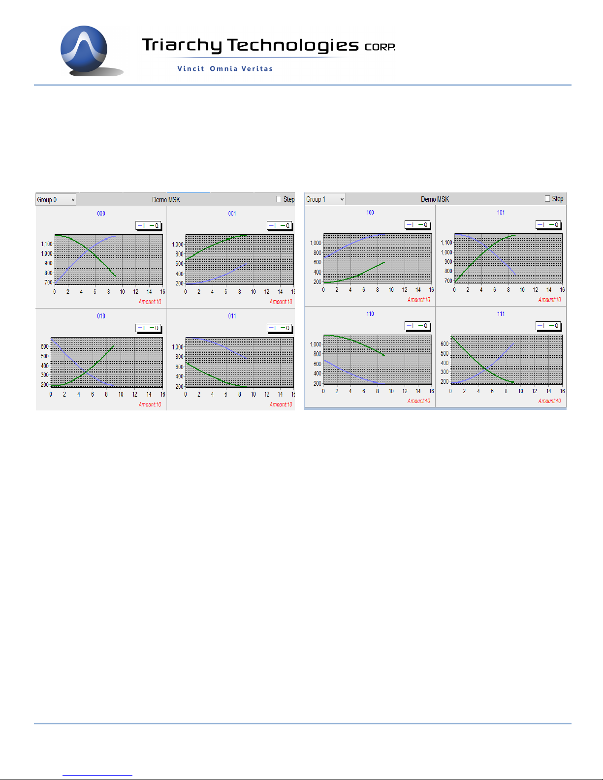
PatternI_110,683,605,529,456,390,330,279,238,208,189
PatternQ_110,1183,1177,1159,1129,1088,1037,977,911,838,762
PatternI_111,183,189,207,237,278,329,388,455,527,604
PatternQ_111,684,606,529,457,390,330,279,238,208,189
9248 163 Street
Surrey, BC V4N 3C9
604-637-2167
info@triarchytech.com
Page 27 of 27
 Loading...