

Page 1
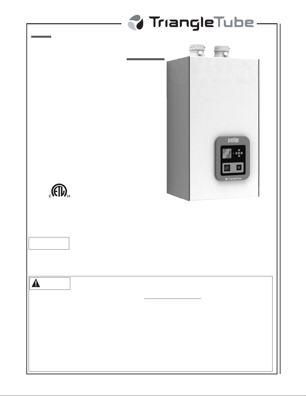
prestige
Solo 60
Solo 175
Solo 250
Solo 399
Water Boiler
* I N S T A L L A T I O N A N D M A I N T E N A N C E *
L
I
S
T
E
D
* I N S T A L L A T I O N A N D M A I N T E N A N C E *
M A N U A L
M A N U A L
NOTICE
WARNING
Warranty Registration Card must be filled out by the customer and mailed within thirty (30) days of installation in order to gain warranty coverage.
When receiving the PRESTIGE Solo unit, any claims for damage or shortage in shipment must be filed
immediately against the transportation company by the consignee.
Leave all documentation received with appliance with owner for future reference.
If the information in this manual is not followed exactly, a fire or explosion may
result causing property damage, personal injury or death.
• Do not store or use gasoline or other flammable vapors and liquids in the vicinity of
this or any other appliance.
• WHAT TO DO IF YOU SMELL GAS
- Do not try to light any appliance
- Do not touch any electrical switch; do not use any phone in your building.
- Immediately call your gas supplier from a neighbor’s phone. Follow the gas
supplier’s instructions.
- If you cannot reach your gas supplier, call the fire department.
Installation and service must be performed by a qualified installer, service agency or the
gas supplier.
FOR YOUR SAFETY
2011-50 Manual Prestige 60/175/250/399_TriMax_Revised 5/29/12
Page 2
Table of Contents
PRODUCT AND SAFETY INFORMATION
Definitions. . . . . . . . . . . . . . . . . . . . . . . . . . . . . . . . . . . . . . . . . . . . . . . . . . . 1
Product and Safety Information . . . . . . . . . . . . . . . . . . . . . . . . . . . . . . . . . . 2
SECTION I - PRE-INSTALLATION ITEMS
Code Compliance . . . . . . . . . . . . . . . . . . . . . . . . . . . . . . . . . . . . . . . . . . . . . 3
Determining Product Location . . . . . . . . . . . . . . . . . . . . . . . . . . . . . . . . . . . 3
Boiler Replacement. . . . . . . . . . . . . . . . . . . . . . . . . . . . . . . . . . . . . . . . . . . . 3
Recommended Clearances . . . . . . . . . . . . . . . . . . . . . . . . . . . . . . . . . . . . . . 3-4
Residential Garage Installations . . . . . . . . . . . . . . . . . . . . . . . . . . . . . . . . . 4
Boiler Freeze Protection Feature . . . . . . . . . . . . . . . . . . . . . . . . . . . . . . . . . 4
SECTION II - COMBUSTION AIR AND VENTING
Combustion Air Contamination . . . . . . . . . . . . . . . . . . . . . . . . . . . . . . . . . . 5
Ventilation and Combustion Air Requirements - Direct Vent . . . . . . . . . . . 6
Ventilation and Combustion Air Requirements - Category IV . . . . . . . . . . 6
Methods of Accessing Combustion Air into a Space - Category IV . . . . . . 7
- Indoor Combustion Air. . . . . . . . . . . . . . . . . . . . . . . . . . . . . . . . . . 7
- Outdoor Combustion Air . . . . . . . . . . . . . . . . . . . . . . . . . . . . . . . . 7-8
- Combination of Indoor and Outdoor Combustion Air. . . . . . . . . . 9
Combustion Air and Vent Piping . . . . . . . . . . . . . . . . . . . . . . . . . . . . . . . . . 9
Removal of an Existing Boiler from a Common Vent System . . . . . . . . . . 10
Commonwealth of Massachusetts Installation . . . . . . . . . . . . . . . . . . . . . . . 11
SECTION III - UNIT PREPARATIONS
Handling Instructions . . . . . . . . . . . . . . . . . . . . . . . . . . . . . . . . . . . . . . . . . . 12
Wall Mounting Installation . . . . . . . . . . . . . . . . . . . . . . . . . . . . . . . . . . . . . . 12
Wall Mounting Guidelines . . . . . . . . . . . . . . . . . . . . . . . . . . . . . . . . . . . . . . 12
Wall Bracket Installation - Stud Walls . . . . . . . . . . . . . . . . . . . . . . . . . . . . . 13
Wall Bracket Installation - Solid Walls . . . . . . . . . . . . . . . . . . . . . . . . . . . . 13
Boiler Mounting . . . . . . . . . . . . . . . . . . . . . . . . . . . . . . . . . . . . . . . . . . . . . . 13
SECTION IV - BOILER PIPING
General Piping Requirements . . . . . . . . . . . . . . . . . . . . . . . . . . . . . . . . . . . . 14
Pressure Relief Valve . . . . . . . . . . . . . . . . . . . . . . . . . . . . . . . . . . . . . . . . . . 14
Low Water Cut Off Device . . . . . . . . . . . . . . . . . . . . . . . . . . . . . . . . . . . . . . 14
Additional Limit Control . . . . . . . . . . . . . . . . . . . . . . . . . . . . . . . . . . . . . . . 16
Backflow Preventer. . . . . . . . . . . . . . . . . . . . . . . . . . . . . . . . . . . . . . . . . . . . 16
i
Page 3
Table of Contents
Boiler System Piping Applications. . . . . . . . . . . . . . . . . . . . . . . . . . . . . . . . 16
Expansion Tank and Makeup Water . . . . . . . . . . . . . . . . . . . . . . . . . . . . . . . 16-17
Diaphragm Expansion Tank . . . . . . . . . . . . . . . . . . . . . . . . . . . . . . . 17
Closed-Type Expansion Tank . . . . . . . . . . . . . . . . . . . . . . . . . . . . . . 17
Circulator . . . . . . . . . . . . . . . . . . . . . . . . . . . . . . . . . . . . . . . . . . . . . . . . . . . 17
Sizing Primary Piping. . . . . . . . . . . . . . . . . . . . . . . . . . . . . . . . . . . . . . . . . . 17
Domestic Hot Water System Piping . . . . . . . . . . . . . . . . . . . . . . . . . . . . . . . 17
System Piping - Zone Circulators. . . . . . . . . . . . . . . . . . . . . . . . . . . . . . . . . 17
System Piping - Zone Valves . . . . . . . . . . . . . . . . . . . . . . . . . . . . . . . . . . . . 17
Piping Component Legend . . . . . . . . . . . . . . . . . . . . . . . . . . . . . . . . . . . . . . 18
Near Boiler Piping Diagrams . . . . . . . . . . . . . . . . . . . . . . . . . . . . . . . . . . . . 19
System Piping - Through Boiler. . . . . . . . . . . . . . . . . . . . . . . . . . . . . . . . . . 20
System Piping - Radiant Heating . . . . . . . . . . . . . . . . . . . . . . . . . . . . . . . . . 20
System Piping - Special Applications. . . . . . . . . . . . . . . . . . . . . . . . . . . . . . 20
System Piping - Multiple Units Installation . . . . . . . . . . . . . . . . . . . . . . . . . 20
System Piping Diagrams. . . . . . . . . . . . . . . . . . . . . . . . . . . . . . . . . . . . . . . . 21-23
SECTION V - INSTALLING VENT / COMBUSTION AIR & CONDENSATE DRAIN
Installing Vent and Combustion Air . . . . . . . . . . . . . . . . . . . . . . . . . . . . . . . 24
Installing Condensate Drain Assembly. . . . . . . . . . . . . . . . . . . . . . . . . . . . . 24-25
SECTION VI - GAS PIPING
Gas Supply Piping Connection. . . . . . . . . . . . . . . . . . . . . . . . . . . . . . . . . . . 26
Natural Gas
Pipe Sizing -Natural Gas . . . . . . . . . . . . . . . . . . . . . . . . . . . . . . . . . 27
Natural Gas Supply Pressure Requirements . . . . . . . . . . . . . . . . . . . 27
Propane Gas
Pipe Sizing - Propane Gas . . . . . . . . . . . . . . . . . . . . . . . . . . . . . . . . 28
Propane Gas Supply Pressure Requirements . . . . . . . . . . . . . . . . . . 28
Gas Valve/Venturi Assembly . . . . . . . . . . . . . . . . . . . . . . . . . . . . . . 29
SECTION VII - INTERNAL WIRING
General Requirements. . . . . . . . . . . . . . . . . . . . . . . . . . . . . . . . . . . . . . . . . . 30
Fuse Locations . . . . . . . . . . . . . . . . . . . . . . . . . . . . . . . . . . . . . . . . . . . . . . . 30
Internal Factory Wiring Diagram . . . . . . . . . . . . . . . . . . . . . . . . . . . . . . . . . 31
SECTION VIII - EXTERNAL WIRING
Installation Compliance . . . . . . . . . . . . . . . . . . . . . . . . . . . . . . . . . . . . . . . . 32
Line Voltage Connections . . . . . . . . . . . . . . . . . . . . . . . . . . . . . . . . . . . . . . . 32
Circulator Wiring . . . . . . . . . . . . . . . . . . . . . . . . . . . . . . . . . . . . . . . . . . . . . 32-33
ii
Page 4

Table of Contents
Alarm Wiring . . . . . . . . . . . . . . . . . . . . . . . . . . . . . . . . . . . . . . . . . . . . . . . . 33
Low Voltage Connections . . . . . . . . . . . . . . . . . . . . . . . . . . . . . . . . . . . . . . . 33
Thermostat Wiring . . . . . . . . . . . . . . . . . . . . . . . . . . . . . . . . . . . . . . . . . . . . 33-34
Outdoor Sensor Wiring. . . . . . . . . . . . . . . . . . . . . . . . . . . . . . . . . . . . . . . . . 34
Domestic Hot Water Wiring . . . . . . . . . . . . . . . . . . . . . . . . . . . . . . . . . . . . . 34
Additional Boiler Limits. . . . . . . . . . . . . . . . . . . . . . . . . . . . . . . . . . . . . . . . 34
External Modulation Control . . . . . . . . . . . . . . . . . . . . . . . . . . . . . . . . . . . . 34
System Sensor Wiring. . . . . . . . . . . . . . . . . . . . . . . . . . . . . . . . . . . . . . . . . . 34-35
Cascade Wiring. . . . . . . . . . . . . . . . . . . . . . . . . . . . . . . . . . . . . . . . . . . . . . . 35
Modbus Wiring . . . . . . . . . . . . . . . . . . . . . . . . . . . . . . . . . . . . . . . . . . . . . . . 35
Zone Valve Wiring . . . . . . . . . . . . . . . . . . . . . . . . . . . . . . . . . . . . . . . . . . . . 36
Zone Circulator Wiring. . . . . . . . . . . . . . . . . . . . . . . . . . . . . . . . . . . . . . . . . 37
System Piping Wiring Diagrams . . . . . . . . . . . . . . . . . . . . . . . . . . . . . . . . . 38-39
SECTION IX - TRIMAX OPERATION
TriMax User Interface . . . . . . . . . . . . . . . . . . . . . . . . . . . . . . . . . . . . . . . . . 40
TriMax Navigation . . . . . . . . . . . . . . . . . . . . . . . . . . . . . . . . . . . . . . . . . . . . 41
Trimax Menu Structure. . . . . . . . . . . . . . . . . . . . . . . . . . . . . . . . . . . . . . . . . 42
Home Screen. . . . . . . . . . . . . . . . . . . . . . . . . . . . . . . . . . . . . . . . . . . . . . . . . 43
Status Line Messages . . . . . . . . . . . . . . . . . . . . . . . . . . . . . . . . . . . . . . . . . . 44
Main Menu . . . . . . . . . . . . . . . . . . . . . . . . . . . . . . . . . . . . . . . . . . . . . . . . . . 45
EZ Setup Menu . . . . . . . . . . . . . . . . . . . . . . . . . . . . . . . . . . . . . . . . . . . . . . . 46
Heating EZ Setup . . . . . . . . . . . . . . . . . . . . . . . . . . . . . . . . . . . . . . . . . . . . . 46-47
Domestic Hot Water EZ Setup . . . . . . . . . . . . . . . . . . . . . . . . . . . . . . . . . . . 48-49
EZ Setup Reset . . . . . . . . . . . . . . . . . . . . . . . . . . . . . . . . . . . . . . . . . . . . . . . 49
Display EZ Setup . . . . . . . . . . . . . . . . . . . . . . . . . . . . . . . . . . . . . . . . . . . . . 49
CH/DHW Operation . . . . . . . . . . . . . . . . . . . . . . . . . . . . . . . . . . . . . . . . . . 50
Boiler Information . . . . . . . . . . . . . . . . . . . . . . . . . . . . . . . . . . . . . . . . . . . . 50
Information Items . . . . . . . . . . . . . . . . . . . . . . . . . . . . . . . . . . . . . . . . . . . . . 51
Lockout History . . . . . . . . . . . . . . . . . . . . . . . . . . . . . . . . . . . . . . . . . . . . . . 52
Lockout Screen . . . . . . . . . . . . . . . . . . . . . . . . . . . . . . . . . . . . . . . . . . . . . . . 53
Manual Reset Hard Lockouts . . . . . . . . . . . . . . . . . . . . . . . . . . . . . . . . . . . . 54
Automatic Reset Soft Lockouts . . . . . . . . . . . . . . . . . . . . . . . . . . . . . . . . . . 55
SECTION X - START-UP PREPARATION
Check Boiler System Water Chemistry
Water pH Level 6.0 to 8.0 . . . . . . . . . . . . . . . . . . . . . . . . . . . . . . . . 56
Water Hardness Less Than 7 Grains. . . . . . . . . . . . . . . . . . . . . . . . . 56
Chlorinated Water . . . . . . . . . . . . . . . . . . . . . . . . . . . . . . . . . . . . . . . 56
Flush Boiler System to Remove Sediment. . . . . . . . . . . . . . . . . . . . . . . . . . 56
Cleaning of Old Boiler/System. . . . . . . . . . . . . . . . . . . . . . . . . . . . . . . . . . . 56
iii
Page 5
Table of Contents
Cleaning of New Boiler/System . . . . . . . . . . . . . . . . . . . . . . . . . . . . . . . . . . 56
Check and Test Antifreeze . . . . . . . . . . . . . . . . . . . . . . . . . . . . . . . . . . . . . . 57
Use of Antifreeze in the Boiler System . . . . . . . . . . . . . . . . . . . . . . . . . . . . 57
Filling the Boiler System . . . . . . . . . . . . . . . . . . . . . . . . . . . . . . . . . . . . . . . 57
Check Low Water Cut-Off Device . . . . . . . . . . . . . . . . . . . . . . . . . . . . . . . 57
Check for Gas Leaks. . . . . . . . . . . . . . . . . . . . . . . . . . . . . . . . . . . . . . . . . . . 58
Check Thermostat Circuit. . . . . . . . . . . . . . . . . . . . . . . . . . . . . . . . . . . . . . . 58
Inspection of Condensate Drain Assembly. . . . . . . . . . . . . . . . . . . . . . . . . . 58
SECTION XI- START-UP PROCEDURES
Final Checks Before Start-Up. . . . . . . . . . . . . . . . . . . . . . . . . . . . . . . . . . . . 59
PRESTIGE Solo Start-Up. . . . . . . . . . . . . . . . . . . . . . . . . . . . . . . . . . . . . . . 59
If PRESTIGE Solo does Not Start Correctly . . . . . . . . . . . . . . . . . . . . . . . . 59
Check the PRESTIGE Solo and System . . . . . . . . . . . . . . . . . . . . . . . . . . . 59-61
Operating Instructions. . . . . . . . . . . . . . . . . . . . . . . . . . . . . . . . . . . . . . . . . . 62
SECTION XII - OUTDOOR RESET CONTROL
Mounting the Outdoor Sensor . . . . . . . . . . . . . . . . . . . . . . . . . . . . . . . . . . . 63
Wiring the Sensor . . . . . . . . . . . . . . . . . . . . . . . . . . . . . . . . . . . . . . . . . . . . . 63
SECTION XIII - EXTERNAL MODULATING CONTROL
Wiring the Modulating Controller . . . . . . . . . . . . . . . . . . . . . . . . . . . . . . . . 64
TriMax Adjustment. . . . . . . . . . . . . . . . . . . . . . . . . . . . . . . . . . . . . . . . . . . . 64
Programming of External Modulating Control . . . . . . . . . . . . . . . . . . . . . . 64
Factory TriMax Settings . . . . . . . . . . . . . . . . . . . . . . . . . . . . . . . . . . . . . . . . 65
SECTION XIV - CHECK-OUT PROCEDURES
Check-Out Procedures . . . . . . . . . . . . . . . . . . . . . . . . . . . . . . . . . . . . . . . . . 66
SECTION XV - INSTALLATION RECORD
Installation Record . . . . . . . . . . . . . . . . . . . . . . . . . . . . . . . . . . . . . . . . . . . . 67
SECTIONS XVI - MAINTENANCE SCHEDULE
Service Technician - General . . . . . . . . . . . . . . . . . . . . . . . . . . . . . . . . . . . . 68
Owner Maintenance . . . . . . . . . . . . . . . . . . . . . . . . . . . . . . . . . . . . . . . . . . . 68
iv
Page 6

Table of Contents
SECTION XVII - MAINTENANCE PROCEDURES
Maintenance Procedures
Reported Problems . . . . . . . . . . . . . . . . . . . . . . . . . . . . . . . . . . . . . . 69
Check Surrounding Area. . . . . . . . . . . . . . . . . . . . . . . . . . . . . . . . . . 69
Inspect Burner Area . . . . . . . . . . . . . . . . . . . . . . . . . . . . . . . . . . . . . 69
Check System Piping . . . . . . . . . . . . . . . . . . . . . . . . . . . . . . . . . . . . 69
Clean Condensate Drain Assembly . . . . . . . . . . . . . . . . . . . . . . . . . 70
Check Ventilation Air Openings . . . . . . . . . . . . . . . . . . . . . . . . . . . . 70
Inspect Vent and Combustion Air Piping . . . . . . . . . . . . . . . . . . . . . 70
Check Boiler System . . . . . . . . . . . . . . . . . . . . . . . . . . . . . . . . . . . . 70
Check Expansion Tank . . . . . . . . . . . . . . . . . . . . . . . . . . . . . . . . . . . 71
Check Boiler Relief Valve . . . . . . . . . . . . . . . . . . . . . . . . . . . . . . . . 71
Inspection of Ignition Electrode . . . . . . . . . . . . . . . . . . . . . . . . . . . . 71
Check Ignition Wiring and Ground Wiring . . . . . . . . . . . . . . . . . . . 71
Check Control Wiring. . . . . . . . . . . . . . . . . . . . . . . . . . . . . . . . . . . . 72
Check Control Settings . . . . . . . . . . . . . . . . . . . . . . . . . . . . . . . . . . . 72
Perform Start-Up and Checkout Procedure . . . . . . . . . . . . . . . . . . . 72
Check Burner Flame . . . . . . . . . . . . . . . . . . . . . . . . . . . . . . . . . . . . . 72
Check Flame Signal . . . . . . . . . . . . . . . . . . . . . . . . . . . . . . . . . . . . . 73
Check Combustion Levels . . . . . . . . . . . . . . . . . . . . . . . . . . . . . . . . 73
Check Flue Gas Temperature . . . . . . . . . . . . . . . . . . . . . . . . . . . . . . 73
Clean Heat Exchanger . . . . . . . . . . . . . . . . . . . . . . . . . . . . . . . . . . . 73
Review with Owner . . . . . . . . . . . . . . . . . . . . . . . . . . . . . . . . . . . . . 74
Handling Previously Fired Combustion Chamber Insulation . . . . . 74
REPLACEMENT PARTS
Replacement Parts. . . . . . . . . . . . . . . . . . . . . . . . . . . . . . . . . . . . . . . . . . . . . 75-83
PRODUCT SPECIFICATIONS
Specifications . . . . . . . . . . . . . . . . . . . . . . . . . . . . . . . . . . . . . . . . . . . . . . . . 84-93
v
Page 7
Product & Safety Information
Definitions
The following terms are used throughout this manual to bring attention to the presence of
potential hazards or important information concerning the product.
DANGER
Indicates the presence of a hazardous
situation which, if ignored, will result in
death, serious injury or substantial
property damage.
WARNING
Indicates a potentially hazardous situation which, if ignored, can result in
death, serious injury or substantial
property damage.
CAUTION
Indicates a potentially hazardous situation which, if ignored, may result in
minor injury or property damage.
NOTICE
Indicates special instructions on installation, operation or maintenance, which
are important to equipment but not
related to personal injury hazards.
BEST PRACTICE
Indicates recommendations made by
Triangle Tube for the installers which
will help to ensure optimum operation
and longevity of the equipment
NOTICE
Triangle Tube reserves the right to modify the technical specifications and components of
its products without prior notice.
1
Page 8
Product & Safety Information
DANGER
Do not use this appliance if any part
has been under water. Immediately call
a qualified service technician to inspect
the appliance and to replace any part of
the control system which has been
under water.
WARNING
WHAT TO DO IF YOU SMELL GAS
- Do not try to light any appliance
- Do not touch any electrical switch; do
not use any phone in your building.
- Immediately call your gas supplier
from a neighbor’s phone. Follow the
gas supplier’s instructions.
- If you cannot reach your gas supplier, call the fire department.
Installation and service must be performed by a qualified installer, service
agency or the gas supplier.
WARNING
Should overheating occur or the gas
supply fails to shut off, turn OFF the
manual gas control valve external to
the appliance.
WARNING
DO NOT add cold make up water when
the boiler is hot. Thermal shock can
cause potential cracks in the heat
exchanger.
CAUTION
When servicing the boiler:
- Avoid electrical shock by disconnecting the electrical supply prior to
performing maintenance.
WARNING
Qualified Installer:
Prior to installing this product read all
instructions included in this manual and all
accompanying manuals/documents with this
appliance. Perform all installation steps
required in these manuals in the proper
order given. Failure to adhere to the guidelines within these manuals can result in
severe personal injury, death or substantial
property damage.
Homeowner:
- This product should be maintained /
serviced and inspected annually by a
qualified service technician.
- This manual is intended for use by a
qualified Installer/Service Technician.
NOTICE
Please reference the unit’s model number and the serial number from the rating label, on the backside of the control
panel when inquiring about service or
troubleshooting.
NOTICE
Triangle Tube accepts no liability for any
damage resulting from incorrect installation or from the use of components or
fittings not specified by Triangle Tube.
2
Page 9
Pre-Installation Items
SECTION I - Pre-Installation Items
Code Compliance
This product must be installed in accordance to
the following:
- All applicable local, state, national and
provincial codes, ordinances, regulations and laws.
- For installations in Massachusetts, code
requires the boiler to be installed by a
licensed plumber or gas fitter, and if
antifreeze is utilized, the installation of
a reduced pressure backflow preventer
device is required in the boiler’s cold
water fill or make up water supply line.
- For installation in Massachusetts all direct
vented appliances must comply with the
guidelines as outlined on page 11.
- The National Fuel Gas Code NFPA54/
ANSI Z 223.1 - Latest edition.
- National Electric Code ANSI/NFPA 70.
- For installations in Canada -“Installation
Code for Gas Burning Equipment”
CGA/B149.1 or B149.2 Canadian
Electrical Code Part 1 CSA C22.1.
- Standards for Controls and Safety
Devices for Automatically Fired Boilers,
ANSI/ASME CSD-1, when required.
Ensure the boiler location allows the combustion air/vent piping to be routed directly through
the building and terminate properly outside with
a minimum amount of length and bends.
Ensure the area chosen for the installation of the
PRESTIGE Solo is free of any combustible
materials, gasoline and other flammable liquids.
WARNING
Failure to remove or maintain the area
free of combustible materials, gasoline
and other flammable liquids or vapors
can result in severe personal injury,
death or substantial property damage.
Ensure the PRESTIGE Solo and its controls
are protected from dripping or spraying water
during normal operation or service.
The PRESTIGE Solo should be installed in a
location so that any water leaking from the
boiler or piping connections or relief valve will
not cause damage to the area surrounding the
unit or any lower floors in the structure.
Boiler Replacement
If the PRESTIGE Solo is replacing an existing
boiler, the following items should be checked
and corrected prior to installation:
NOTICE
The PRESTIGE Solo boiler gas manifold
and gas controls meet the safe lighting and
other performance requirements as specified in ANSI Z21.13 latest edition.
Determining Product Location
Before locating the PRESTIGE SOLO check
for convenient locations to:
- Heating system piping
- Venting
- Gas supply piping
- Electrical service
- Boiler piping leaks and corrosion.
- Improper location and sizing of the
expansion tank on the boiler heating
loop.
- If applicable, level and quality of freeze
protection within the boiler system.
Recommended Clearances
The PRESTIGE Solo is approved for zero
clearance to combustibles, excluding vent and
boiler piping.
- Boiler Piping - 1/4 inch from combustible materials.
3
Page 10
Pre-Installation Items
- Reference the appropriate vent supplement for clearance requirements.
BEST PRACTICE
To provide serviceability to the unit it is
recommended that the following clearances be maintained:
Top boiler jacket - 24 inches [610 mm].
Front - 24 inches [610 mm].
Bottom boiler piping - 24 inches [610
mm].
Rear - 0 inches
Sides - 6 inches [153 mm]
WARNING
If the clearances listed above cannot be
maintained or the enclosure in which the
boiler is installed is less than 85 cubic feet,
the space must be ventilated. See page 6
for ventilation requirements.
NOTICE
Residential Garage Installations
When installing the PRESTIGE Solo in a residential garage, the following special precautions
per NFPA 54/ANSI Z223.1 must be taken:
- Mount the unit a minimum 18 inches
[458 mm] above the floor level of the
garage. Ensure the burner and ignition
devices / controls are no less than 18
inches [458 mm] above the floor level.
- Locate or protect the unit in a manner so it
cannot be damaged by a moving vehicle.
Boiler Freeze Protection Feature
The TriMax boiler management system has a
freeze protection feature built in. This feature
monitors the boiler temperature and responds as
follows when no call for heat is present:
- 46ºF [8ºC] CH (1) & Auxiliary Boiler
Pumps ON
- 42ºF [6ºC] CH (1), Auxiliary Boiler &
System Pumps ON, Burner operates at
low fire
- 60ºF [15ºC] Freeze protection ends.
Burner & all pumps OFF after completing CH Post Pump Time.
When maintaining zero clearance or less
than recommended clearances, some
product labeling may become hidden
and unreadable.
WARNING
When installing the PRESTIGE Solo in
a confined space, sufficient air must be
provided for proper combustion and
venting and to allow, under normal operating conditions, proper air flow around
the product to maintain ambient temperatures within safe limits to comply
with the National Fuel Gas Code NFPA
54 - latest edition.
CAUTION
The boiler freeze protection feature is
disabled during a hard lockout, however
the circulators will operate.
CAUTION
The boiler freeze protection feature is
designed to protect the boiler. The boiler
should be installed in a primary/secondary piping arrangement if it is
installed in an unheated space or
exposed to water temperatures of 46ºF or
less. See Section IV for primary/secondary piping examples. See Section X
for antifreeze guides.
4
Page 11
Combustion Air Venting
SECTION II - Combustion Air and
Venting
Combustion Air Contamination
WARNING
If the PRESTIGE Solo combustion air
inlet is located in any area likely to cause
or contain contamination, or if products,
which would contaminate the air cannot
be removed, the combustion air must be
repiped and terminated to another location. Contaminated combustion air will
damage the unit and its burner system,
resulting in possible severe personal
injury, death or substantial property
damage.
WARNING
Do not operate a PRESTIGE Solo if its
combustion air inlet is located near a
laundry room or pool facility. These
areas will always contain hazardous contaminants.
Potential contaminating products
- Spray cans containing chloro/fluorocarbons
- Permanent Wave Solutions
- Chlorinated wax
- Chlorine - based swimming pool chemicals / cleaners
- Calcium Chloride used for thawing ice
- Sodium Chloride used for water softening
- Refrigerant leaks
- Paint or varnish removers
- Hydrochloric acid / muriatic acid
- Cements and glues
- Antistatic fabric softeners used in
clothes dryers
- Chlorine-type bleaches, detergents, and
cleaning solvents found in household
laundry rooms
- Adhesives used to fasten building products and other similar products
Pool and laundry products and common
household and hobby products often
contain fluorine or chlorine compounds.
When these chemicals pass through the
burner and vent system, they can form
strong acids. These acids can create corrosion of the heat exchanger, burner
components and vent system, causing
serious damage and presenting a possible threat of flue gas spillage or water
leakage into the surrounding area.
Please read the information listed below.
If contaminating chemicals are located
near the area of the combustion air inlet,
the installer should pipe the combustion
air inlet to an outside area free of these
chemicals per SECTION V of this
installation manual.
Areas likely to contain these products
- Dry cleaning / laundry areas and establishments
- Beauty salons
- Metal fabrication shops
- Swimming pools and health spas
- Refrigeration Repair shops
- Photo processing plants
- Auto body shops
- Plastic manufacturing plants
- Furniture refinishing areas and establishments
- New building construction
- Remodeling areas
- Garages with workshops
5
Page 12
Combustion Air Venting
Ventilation and Combustion Air
Requirements - Direct Vent
A Direct Vent appliance utilizes uncontamined
outdoor air (piped directly to the appliance) for
combustion.
For Direct Vent installations, involving only
the PRESTIGE Solo, in which the minimum
service clearances are maintained as listed on
page 4, no ventilation openings are required.
For Direct Vent, zero clearance installations
involving only the PRESTIGE Solo, the space
/ enclosure must provide two openings for ventilation. The openings must be sized to provide
1 square inch of free area per 1,000 BTUH of
boiler input. The openings shall be placed 12
inches from the top of the space and 12 inches
from the floor of the space.
For installations in which the PRESTIGE Solo
shares the space with air movers (exhaust fan,
clothes dryers, fireplaces, etc.) and other combustion equipment (gas or oil) the space must
be provided with adequate air openings to provide ventilation and combustion air to the
equipment. To properly size the ventilation /
combustion air openings, the installer must
comply with the National Fuel Gas Code
NFPA 54, ANSI Z223.1 for installations in the
U.S or CSA B149.1 and B149.2 for installations in Canada.
WARNING
The space must be provided with ventilation / combustion air openings properly sized for all make-up air requirements
(exhaust fans, clothes dryers, fireplaces,
etc.) and the total input of all appliances
located in the same space as the PRESTIGE Solo, excluding the input of a
Direct Vent PRESTIGE Solo which uses
combustion air directly from the outside,
thus additional free area for the openings is not required. Failure to provide
or properly size the openings could
result in severe personal injury, death or
substantial property damage.
Ventilation and Combustion Air
Requirements - Category IV
A Category IV appliance utilizes uncontaminated indoor or outdoor air (surrounding the
appliance) for combustion.
BEST PRACTICE
In order to reduce the potential risks
associated with indoor contaminates
(listed on page 5), flammable vapors and
tight housing construction (little or no
infiltration air), it is recommended to
pipe uncontaminated combustion air
directly from the outdoors to the appliance. This practice also promotes higher
system efficiency by reducing heated
indoor air from being exhausted from
the house and replaced by cold infiltration air into the house.
For installations in which the PRESTIGE Solo
shares the space with air movers (exhaust fan,
clothes dryers, fireplaces, etc.) and other combustion equipment (gas or oil) the space must
be provided with adequate air openings to provide ventilation and combustion air to the equipment. To properly size the ventilation / combustion air openings, the installer must comply
with the National Fuel Gas Code NFPA 54,
ANSI Z223.1 for installations in the U.S or CSA
B149.1 and B149.2 for installations in Canada,
as referenced in this section of the manual and
titled Methods of Accessing Combustion Air
into a Space.
WARNING
The space must be provided with ventilation / combustion air openings properly sized for all make-up air requirements
(exhaust fans, clothes dryers, fireplaces,
etc.) and the total input of all appliances,
including the PRESTIGE Solo when
located in the same space. Failure to provide or properly size the openings could
result in severe personal injury, death or
substantial property damage.
6
Page 13
Combustion Air Venting
Methods of Accessing Combustion Air Into A
Space - Category IV
Indoor Combustion Air
NOTICE
The methods listed in this section for
accessing Indoor Combustion Air
assume that the infiltration rate is adequate and not less than .40 ACH. For
infiltration rates less than .40 ACH, reference the NFPA 54 National Fuel Gas
Code for additional guidance.
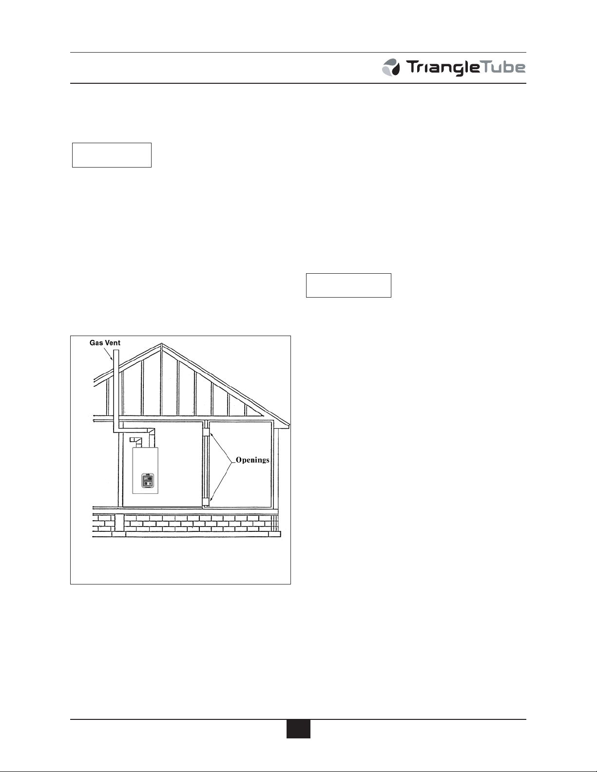
Opening Size and Location
Openings used to connect indoor spaces shall
be sized and located in accordance with the
following see Fig. 1:
The minimum dimension of air openings shall be not less than 3 inches.
- Combining spaces in different stories.
The volumes of spaces in different stories shall be considered as communicating spaces where such spaces are connected by one or more openings in
doors or floors having a total minimum
free area of 2 sq. in./1000 Btu/hr of
total input rating of all gas utilization
equipment.
Outdoor Combustion Air
BEST PRACTICE
Isolating the combustion appliance room
from the rest of the building and bringing in uncontaminated outside air for
combustion and ventilation is always
preferred.
Fig. 1:
All Combustion Air from Adjacent
Indoor Spaces Through Indoor
Combustion Openings
- Combining spaces on the same story.
Each opening shall have a minimum
free area of 1 sq. in./1000 Btu/hr of the
total input rating of all gas utilization
equipment in the space, but not less than
100 sq. inches. One opening shall commence within 12 inches of the top, and
one opening shall commence within 12
inches of the bottom of the enclosure.
Opening Size and Location
The minimum dimension of air openings shall
be not less than 3 inches
Openings used to supply combustion and ventilation air shall be sized and located in accordance with the following:
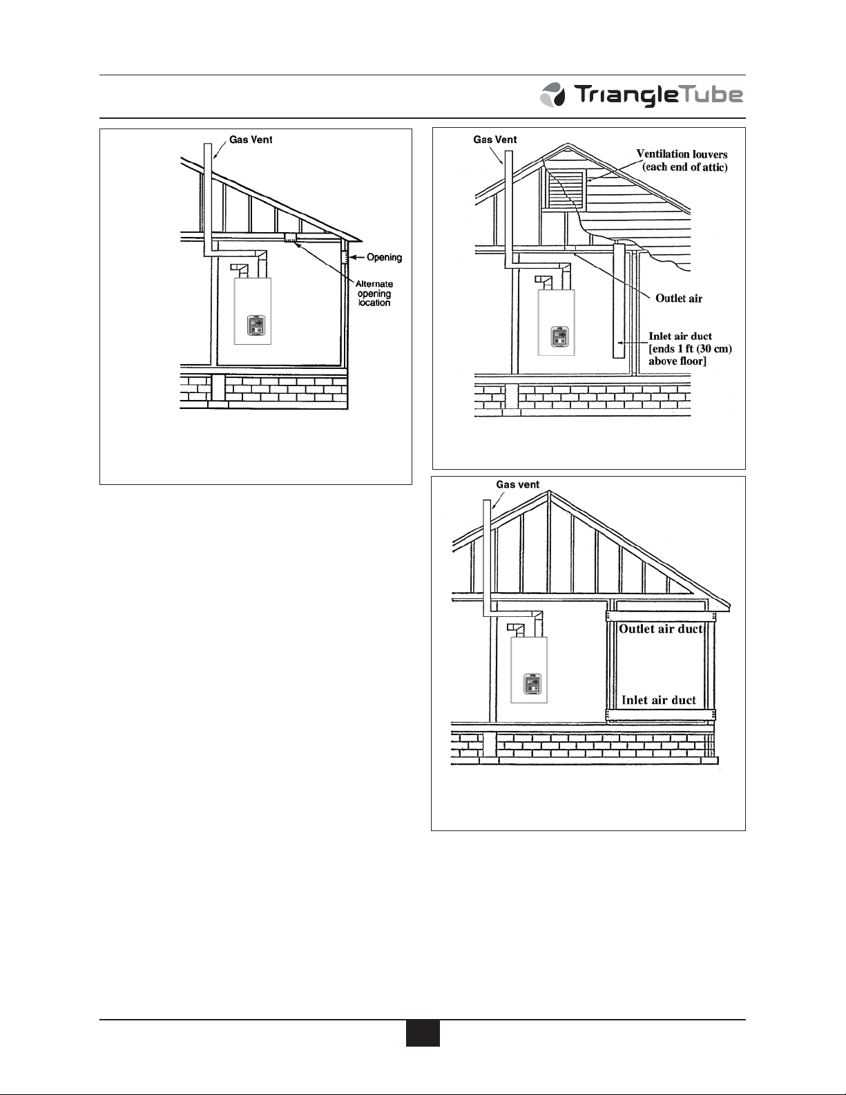
One Permanent Opening Method. See Fig. 2
One permanent opening, commencing within 12
in. of the top of the enclosure, shall be provided.
The equipment shall have clearances of at least 1
inch from the sides and 6 in. from the front of the
appliance. The opening shall directly communicate with the outdoors or shall communicate
through a vertical or horizontal duct to the outdoors or spaces that freely communicate with the
outdoors and shall have a minimum free area of
the following:
- 1sq. in./3000 Btu/hr of the total input
rating of all equipment located in the
enclosures, and
7
Page 14
Combustion Air Venting
Fig. 2:
All Combustion Air from Outdoors
Through One Permanent Air
Opening
- Not less than the sum of the areas of all
vent connectors in the space.
Two Permanent Openings Method.
Two permanent openings, one commencing
within 12 in. of the top and one commencing
within 12 in. of the bottom of the enclosure,
shall be provided. The openings shall communicate directly, or by ducts, with the outdoors
or spaces that freely communicate with the outdoors, as follows:
- Where directly communicating with the
outdoors or where communication to the
outdoors is through vertical ducts, each
opening shall have a minimum free area
of 1 sq. in./4000 Btu/hr of total input rating of all equipment in the enclosure.
See Fig.3.
Fig. 3:
Fig. 4:
All Combustion Air from Outdoors
Through Ventilated Attic
All Combustion Air from Outdoors
Through Horizontal Ducts
- Where communicating with the outdoors is through horizontal ducts, each
opening shall have a minimum free
area of not less than 1 sq.in./2000
Btu/hr of total input rating of all equipment in the enclosure. See Fig. 4.
8
Page 15
Combustion Air Venting
Combination of Indoor and Outdoor
Combustion Air
Indoor Openings: Where used, openings connecting the interior spaces shall comply with
the Indoor Combustion Air section on page 7.
Outdoor Opening(s) Location. Outdoor opening(s) shall be located in accordance with the
Outdoor Combustion Air section.
Outdoor Opening(s) Size. Outdoor opening(s) shall
be calculated in accordance with the following:
- The ratio of the interior spaces shall be
the available volume of all communicating spaces divided by the required
volume.
- The outdoor size reduction factor shall
be 1 minus the ratio of interior spaces.
- The minimum size of outdoor opening(s) calculated in accordance with the
above outdoor air section multiplied by
the reduction factor. The minimum
dimension of air openings shall not be
less than 3 in.
DANGER
Do not install the PRESTIGE Solo into a
common vent with other gas or oil appliances. This may cause flue gas spillage or
appliance malfunction, resulting in possible severe personal injury, death or substantial property damage.
Combustion Air and Vent Piping
The PRESTIGE Solo requires a Category IV
venting system, which is designed for pressurized venting and condensate.
The PRESTIGE Solo is certified per ANSI
Z21.13 as a Category IV or Direct Vent (sealed
combustion) appliance. A Category IV appliance utilizes uncontamined indoor or outdoor
air (surrounding the appliance) for combustion.
A Direct Vent appliance utilizes uncontaminated outdoor air (piped directly to the appliance)
for combustion.
BEST PRACTICE
In order to reduce the potential risks
associated with indoor contaminates
(listed on page 5), flammable vapors
and tight housing construction (little or
no infiltration air), it is recommended
to pipe uncontaminated combustion air
directly from the outdoors to the appliance. This practice also promotes higher
system efficiency by reducing heated
indoor air from being exhausted from
the house and replaced by cold infiltration air into the house.
NOTICE
Install combustion air and vent pipe as
detailed in the PRESTIGE Solo Vent
Supplement included in the boiler
installation envelope. Refer to optional
vent kit instructions for addition vent
installation instructions.
DANGER
Verify installed combustion air and vent
piping are sealed gas tight and meet all
provided instructions and applicable
codes, failure to comply will result in
severe personal injury of death.
9
Page 16
Combustion Air Venting
Removal of an Existing Boiler from a
Common Vent System
BEST PRACTICE
When an existing boiler is removed from a
common venting system, the common venting
system is likely to be too large for proper
venting of the remaining appliances. At the
time of removal of an existing boiler, the following steps shall be followed with each
appliance remaining connected to the common venting system placed in operation,
while the other appliances remaining connected to the common venting system are not
in operation.
1. Seal any unused openings in the common
venting system.
2. Visually inspect the venting system for
proper size and horizontal pitch and determine there is no blockage or restriction,
leakage, corrosion and other deficiencies
which could cause an unsafe condition.
5. Test for spillage at the draft hood relief
opening after 5 minutes of main burner
operation. Use the flame of a match or candle, or smoke from a cigarette, cigar or pipe.
6. After it has been determined that each
appliance remaining connected to the common venting system properly vents when
tested as outlined above, return doors, windows, exhaust fans, fireplace dampers, and
any other gas-burning appliance to their
previous condition of use.
7. Any improper operation of the common
venting system should be corrected so the
installation conforms with the National
Fuel Gas Code, ANSI Z223.1/NFPA 54
and/or CAN/CGA B149, Installation codes.
When resizing any portion of the common
venting system, the common venting system should be resized to approach the minimum size as determined using the appropriate tables in Part II of the National Fuel
Gas Code ANSI Z223.1/NFPA 54 and/or
CAN/CGA B149, Installation codes.
3. Insofar as is practical, close all building
doors and windows and all doors between
the space in which the appliances remaining connected to the common venting system are located and other spaces of the
building. Turn on clothes dryers and any
appliance not connected to the common
venting system. Turn on any exhaust fans,
such as range hoods and bathroom
exhausts, so they will operate at maximum
speed. Do not operate a summer exhaust
fan. Close fireplace dampers.
4. Place in operation the appliance being
inspected. Follow the lighting instructions.
Adjust thermostat so appliance will operate
continuously.
DANGER
Do not install the PRESTIGE Solo into a
common vent with other gas or oil appliances. This may cause flue gas spillage or
appliance malfunction, resulting in possible severe personal injury, death or substantial property damage.
10
Page 17

Combustion Air Venting
Commonwealth of Massachusetts Installations Only
For direct-vent appliances, mechanicalvent heating appliances or domestic hot
water equipment, where the bottom of the
vent terminal and the air intake is installed
below four feet above grade the following
requirements must be satisfied:
1. If there is not one already present, on
each floor level where there are bedroom(s), a carbon monoxide detector
and alarm shall be placed in the living
area outside the bedroom(s). The carbon monoxide detector shall comply
with NFPA 720 (2005 Edition).
2. A carbon monoxide detector shall also
be located in the room that houses the
appliance or equipment and shall:
a. Be powered by the same electrical cir-
cuit as the appliance or equipment such
that only one service switch services
both the appliance and the carbon
monoxide detector;
b. Have battery back-up power;
c. Meet ANSI/UL 2034 Standards and
comply with NFPA 720 (2005 Edition);
and
d. Have been approved and listed by the
Nationally Recognized Testing
Laboratory as recognized under 527
CMR.
3. A Product-approved vent terminal must
be used, and if applicable, a Productapproved air intake must be used.
Installation shall be in strict compliance
with the manufacturer’s instructions. A
copy of the installation instructions
shall remain with the appliance or
equipment at the completion of the
installation.
4. A metal or plastic identification plate
shall be mounted at the exterior of the
building, four feet directly above the
location of vent terminal. The plate
shall be of sufficient size to be easily
read from a distance of eight feet away,
and read “Gas Vent Directly Below”.
NOTICE
Installer must provide tag identification
plate and ensure the lettering meets code
requirements.
For direct-vent appliances, mechanicalvent heating appliances or domestic hot
water equipment, where the bottom of the
vent terminal and the air intake are installed
above four feet above grade the following
requirements must be satisfied:
1. If there is not one already present, on
each floor level where there are bedroom(s), a carbon monoxide detector
and alarm shall be placed in the living
area outside the bedroom(s). The carbon monoxide detector shall comply
with NFPA 720 (2005 Edition).
2. A carbon monoxide detector shall:
a. Be located in the room that houses the
appliances or equipment;
b. Be either hard wired or battery powered
or both; and
c. Shall comply with NFPA 720 (2005
Edition)
3. A Product-approved vent terminal must
be used, and if applicable, a Productapproved air intake must be used.
Installation shall be in strict compliance
with the manufacturer’s instructions. A
copy of the installation instructions
shall remain with the appliance or
equipment at the completion of the
installation.
11
Page 18
Unit Preparations
SECTION III - Unit Preparations
Handling Instructions
The PRESTIGE Solo is generally easier to
handle and maneuver once removed from the
shipping carton.
To remove the shipping carton:
CAUTION
Use care not to drop, bump or rotate the
boiler upside down, as damage to the
boiler will result.
1. Remove any shipping straps and open the
side of the shipping carton.
2. Slide the unit with the foam inserts out of
the carton.
3. Discard all packing materials.
Wall Mounting Installation
Wall Mounting Guidelines
1. The wall-mounting bracket is designed for
stud spacing of 12 inch or 16 inch on centers. For unconventional stud spacing, a
solid / secure mounting surface must be
provided for installation of the bracket.
2. For applications using wood studs, install
the bracket using the lag screws provided
with the boiler. Ensure both lag screws are
installed securely in the studs.
3. For applications using metal studs, install
the bracket to the studs using 3/16” toggle
bolts and washers.
4. DO NOT mount or attempt to mount the
wall bracket to hollow sheet rock or lath
walls using anchors. Only install boiler to
studs or equivalent wood structure.
5. For applications using solid walls (rock,
concrete, brick, cinder block, etc.), install
the wall bracket using anchors (double
expansion shields) and bolts with washers
provided with the boiler.
The PRESTIGE Solo should be wall mounted
using the bracket provided with the boiler. The
PRESTIGE Solo is not designed for floor
installation. If floor installation is required an
optional floor stand is available through
Triangle Tube.
NOTICE
The wall used for mounting the PRESTIGE Solo must be vertically plumbed
and capable of supporting a minimum
130 pounds [59 kg] for the PRESTIGE
Solo 60, 175 pounds [80 kg] for PRESTIGE Solo 175/250 and 250 pounds [115
Kg] for PRESTIGE Solo 399. Failure to
comply with these requirements could
result in personal injury, death or substantial property damage.
6. The boiler is too heavy and bulky for a single person to lift and attempt to mount; a
minimum of 2 people is required for
mounting the boiler.
NOTICE
Use extreme care not to drop the boiler
or cause bodily injury while lifting or
mounting the boiler onto the bracket.
Once mounted verify that the boiler is
securely attached to the bracket and
wall. Failure to comply with the above
guidelines could result in property damage, personal injury or death.
12
Page 19

Unit Preparations
PRESTIGE Solo 60/175/250 Stud Walls Installation
1. Locate the studs in the general area of the
boiler placement.
2. Place the wall-mounting bracket on the
wall centering the mounting slots with the
stud centers and ensuring the upper edge of
the bracket is away from the wall.
3. Level the bracket, while maintaining it’s
centering with the studs and use a pencil to
mark the location of the mounting slots.
4. Remove the bracket from the wall and drill
1/4” diameter hole by 3” deep positioned in
the center of each mark. For applications
using metal studs and 3/16” toggle bolts,
drill the required clearance hole.
5. Reposition the bracket onto the wall and
align mounting slots/holes. Insert the two
lag screws provided (or toggle bolts for
metal studs) through the mounting
slots/holes and loosely tighten.
Wall Bracket Installation - Solid Walls
1. Locate the general area of the boiler placement.
2. Place the wall-mounting bracket on the
wall ensuring the upper edge of the bracket
is away from the wall.
3. Level the bracket and use a pencil to mark
the location of the mounting slots on the
wall.
4. Remove the bracket from the wall and drill
a 5/8” diameter hole by 1-3/8” deep positioned in the center of each mark.
5. Install the anchors (provided) flush or
slightly recessed in the drilled holes with
threaded side facing down.
6. Reposition the bracket on the wall and
align mounting slots/holes. Insert the two
bolts (provided) through the mounting
slots/holes and loosely tighten.
7. Level bracket and tighten bolts securely.
6. Level bracket and tighten screws (bolts for
metal studs) securely making sure not to
over-tighten to avoid damaging drywall or
plaster.
PRESTIGE Solo 399 Stud Walls Installation
1. To distribute the weight of the boiler evenly when mounting onto a stud wall it is recommended to use the PRESTIGE Solo
Wall Frame kit.
2. When using the wall frame to mount the
boiler reference the kit installation instructions and ensure the frame is securely fastened to the wall.
3. If the structure of wall is questionable, in
supporting a minimum weight of 250
pounds [115 kg.], it is recommended to use
the optional floor stand.
Boiler Mounting
1. Obtain assistance in lifting the boiler onto
the wall bracket.
2. Install the boiler making sure the boiler
mounting lip located along the upper edge
of the rear jacket panel engages the wallmounting bracket. Ensure the boiler is
seated properly and is secure.
13
Page 20
Boiler Piping
SECTION IV - Boiler Piping
General Piping Requirements
- All plumbing must meet or exceed all local,
state and national plumbing codes.
- Support all piping using hangers. DO NOT
support piping by the unit or its components.
- Use isolation valves to isolate system components.
- Install unions for easy removal of the
PRESTIGE Solo from the system piping.
WARNING
Use a two wrench method when tightening piping onto the boiler connections.
Use one wrench to prevent the boiler
piping from turning / twisting. Failure
to support the boiler piping and connections in this manner could cause damage
to the boiler and its components.
Pressure Relief Valve
1. The PRESTIGE Solo is supplied with a 30
psi pressure relief valve and must be piped
using the PRV connection as shown in Fig.
5 page 15.
2. To avoid potential water damage to the surrounding area or potential scalding hazard
due to the operation of the relief valve, the
discharge piping:
- Must be connected to the discharge out-
let of the relief valve and directed to a
safe place of disposal.
- Length should be as short and direct as
possible. The size of the discharge line
should not be reduced, maintain the
same size as the outlet of the relief valve.
- Should be directed downward towards
the floor at all times. The piping should
terminate at least 6 inches [153 mm]
above any drain connection to allow
clear visibility of the discharge.
- Should terminate with a plain end, not
with a threaded end. The material of
the piping should have a serviceable
temperature rating of 250ºF or greater.
- Should not be subject to conditions
where freezing could occur.
- Should not contain any shut-off valves
or obstructions. No shut-off valve
should be piped between the boiler and
relief valve.
WARNING
Failure to comply with the guidelines on
installing the pressure relief valve and
discharge piping can result in personal
injury, death or substantial property
damage.
Low Water Cutoff Device
- The PRESTIGE Solo is equipped with a factory installed pressure switch type Low Water
Cut Off device.
- The minimum operating system pressure
allowable with this device is 10 psig.
- Check local codes if a Low Water Cutoff
Device is required. If so, determine if this
device meets the requirements of the local
codes.
NOTICE
The PRESTIGE Solo control system also
senses the system water temperatures
entering and exiting the heat exchanger
to provide protection against low water
conditions Where local codes and jurisdiction do not accept a pressure device
for low water protection, the jurisdictions may accept these PRESTIGE Solo
integral control functions as a means of
providing low water protection.
14
Page 21
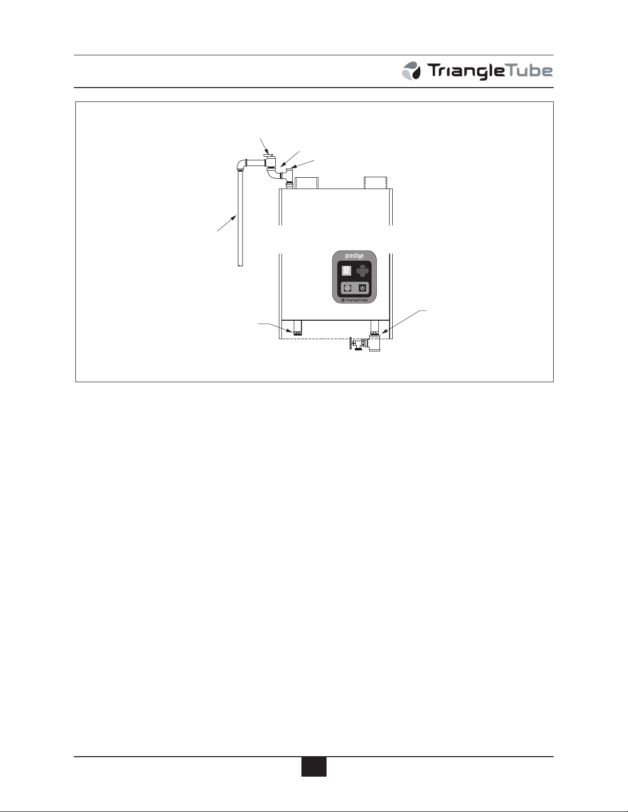
Boiler Piping
Boiler Return Connection
with Tee Fitting and
Boiler Drain Valve
Boiler Supply
Connection
Pressure Relief Valve
(Supplied with Boiler)
3/4" Street Elbow
Air Vent
Drain Piping Directed
to a Suitable
Place of Drainage
Fig. 5: Pressure Relief Valve and Boiler Drain Valve Installation
15
Page 22
Boiler Piping
Additional Limit Control
If a separate LWCO device is required by certain local jurisdictions or when the boiler is
installed above the system piping, the following guidelines must be followed:
- The LWCO device must be designed
for water installations, electrode probetype is recommended.
- The LWCO device must be installed in
a tee connection on the boiler supply
piping above the boiler.
- Wiring of the LWCO device to the PRESTIGE Solo is done directly onto the low
voltage terminal strip, reference Fig. 19
page 31 for available terminals for an
external limit (manual or auto reset).
If the installation is to comply with ASME or
Canadian requirements, an additional high
temperature limit may be needed. Consult
local code requirements to determine compliance. The limit should be installed as follows:
Boiler System Piping Applications
BEST PRACTICE
It is recommended on all piping applications to utilize a primary/secondary piping
arrangement as a means to provide freeze
protection of the boiler, which is an integral
function of the boiler control. Maintain the
minimum boiler flow rate, see Graphs 2
through 7 on pages 91 through 93. For
other piping arrangements, consult the
Engineering Department at Triangle Tube
or consult other approved/recognized
design arrangements.
BEST PRACTICE
On piping applications utilizing a single
zone or other recognized piping design
arrangements, it is recommended that the
installer uses flow/check valves with
weighted seats at or near the appliance to
prevent gravity circulation.
- Install the limit in the boiler supply piping between the boiler and any isolation
valve.
- Maximum set point for the limit is
194ºF.
- For wiring of the limit reference Fig. 19,
page 31, using the external limit/manual
reset terminals on the low voltage terminal strip. This will provide a "hard"
lockout requiring a manual reset of the
control.
Backflow Preventer
- Use a backflow preventer valve in the
make-up water supply to the unit as
required by local codes.
Expansion Tank and Makeup Water
Ensure the expansion tank is properly sized for
the boiler volume (3 gallons [12 L] for the
PRESTIGE Solo 60, 5 gallons [19 L] for the
PRESTIGE Solo 175/250, 7 gallons [26 L] for
PRESTIGE Solo 399) and the system volume
and temperature.
CAUTION
Undersized expansion tanks will cause
system water to be lost through the pressure relief valve and cause additional
makeup water to be added to the system.
Eventual boiler heat exchanger failure
can result due to this excessive makeup
water addition.
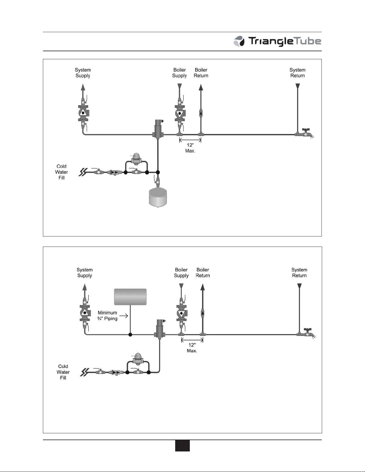
The expansion tank must be located as shown
in Fig. 7 and Fig. 8 on page 19 when using a
primary/secondary piping arrangement or as
per recognized design methods. Refer to the
expansion tank manufacturer instructions for
additional installation details.
16
Page 23
Boiler Piping
Connect the expansion tank to an air separator
only if the air separator is located on the suction side (inlet) of the system circulator.
Always locate and install the system fill connection at the same location as the expansion
tank connection to the system.
Diaphragm Expansion Tank
Always install an automatic air vent on the top
of the air separator to remove residual air from
the system.
Closed-Type Expansion Tank
It is recommended to pitch any horizontal piping
upwards toward the expansion tank 1 inch per 5
feet of piping. Use 3/4” piping for the expansion
tank to allow air within the system to rise.
CAUTION
DO NOT install automatic air vents on a
closed-type expansion tank system. Air
must remain in the system and be
returned to the expansion tank to provide an air cushion. An automatic air
vent would cause air to be vented from
the system resulting in a water-logged
expansion tank.
Circulator
Domestic Hot Water System Piping
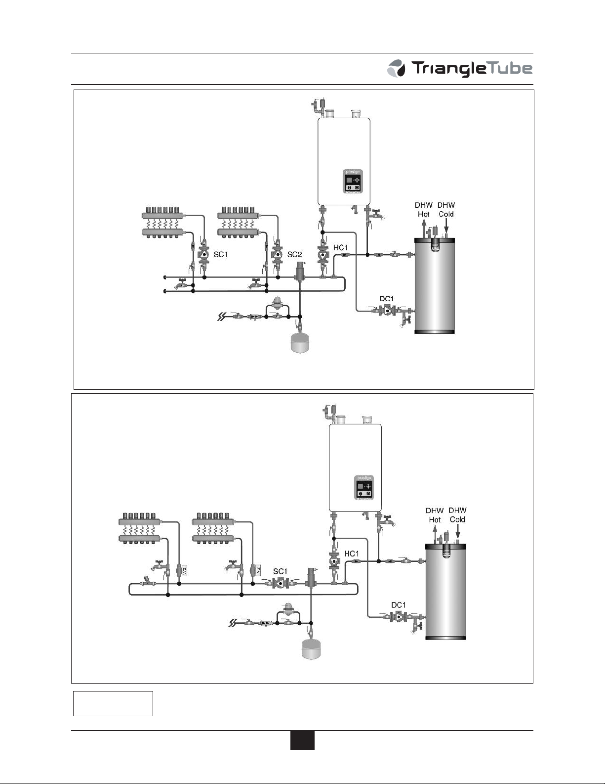
See Fig. 9 through 12, page 21-22 for recommended piping to a DHW system. This recommended piping configuration ensures priority is
given to the production and recovery of the DHW.
The piping for the DHW is separate from the
boiler system piping and does not require a primary / secondary piping configuration.
To wire the DHW circulator to the boiler control
module, reference Section VIII - External Wiring.
System Piping - Zone Circulators
Connect the PRESTIGE Solo to the system
piping as shown in Fig. 9 page 21 when zoning
with zone circulators.
The installer must provide a separate circulator
for each zone of space heating as well as the
boiler circulator.
NOTICE
To ensure an adequate flow rate through
the PRESTIGE Solo, the boiler supply and
return piping size must be a minimum of 1
inch for the PRESTIGE Solo 60, 1-1/4 inch
for the PRESTIGE Solo 175/250 and 1-1/2
inch for the PRESTIGE Solo 399.
The PRESTIGE Solo requires an external circulator to provide circulation through the boiler. The
circulator when wired directly to the PRESTIGE
Solo will allow for domestic hot water priority and
to provide circulation for the freeze protection feature of the boiler control. See Graphs 2 through 7
on pages 91 & 93 for pressure drop and minimum
flow rate through the boiler.
Sizing Primary Piping
See Fig. 9 through 13, pages 21 - 23, for recommended piping arrangements based on various applications. Size the piping and system
components required in the space heating system, using recognized design methods.
System Piping - Zone Valves
Connect the PRESTIGE Solo to the system piping as shown in Fig. 10 page 21 when zoning
with zone valves. The primary / secondary piping
ensures that the boiler loop has sufficient flow.
NOTICE
To ensure an adequate flow rate through
the PRESTIGE Solo, the boiler supply
and return piping size must be a minimum of 1 inch for the PRESTIGE Solo 60,
1-1/4 inch for the PRESTIGE Solo
175/250 and 1-1/2 inch for the PRESTIGE
Solo 399.
17
Page 24
Boiler Piping
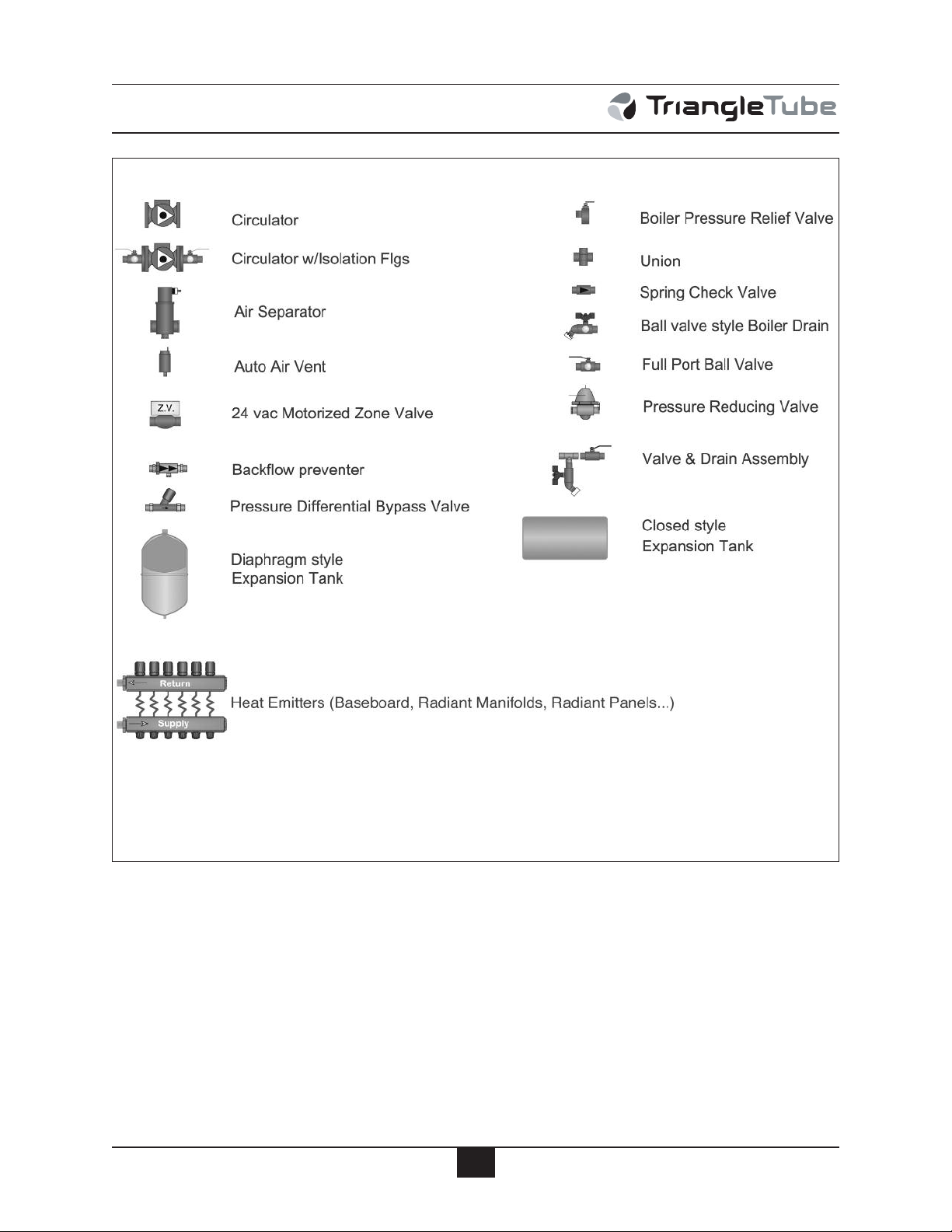
Fig. 6: Piping Component Legend
18
Page 25
Boiler Piping
Fig. 7: Near Boiler Piping - Diaphragm Expansion Tank
Note: Pitch horizontal pip-
ing upwards (1” of pitch
per 5 ft of piping) towards
expansion tank.
Fig. 8 : Near Boiler Piping - Closed Type Expansion Tank
19
Page 26
Boiler Piping
System Piping - Through Boiler
In new or retrofit applications in which
primary/secondary arrangement is not utilized, the
PRESTIGE Solo allows this flexibility due to a
lower boiler pressure drop, see Graphs 2 through
7 on pages 91 through 93.
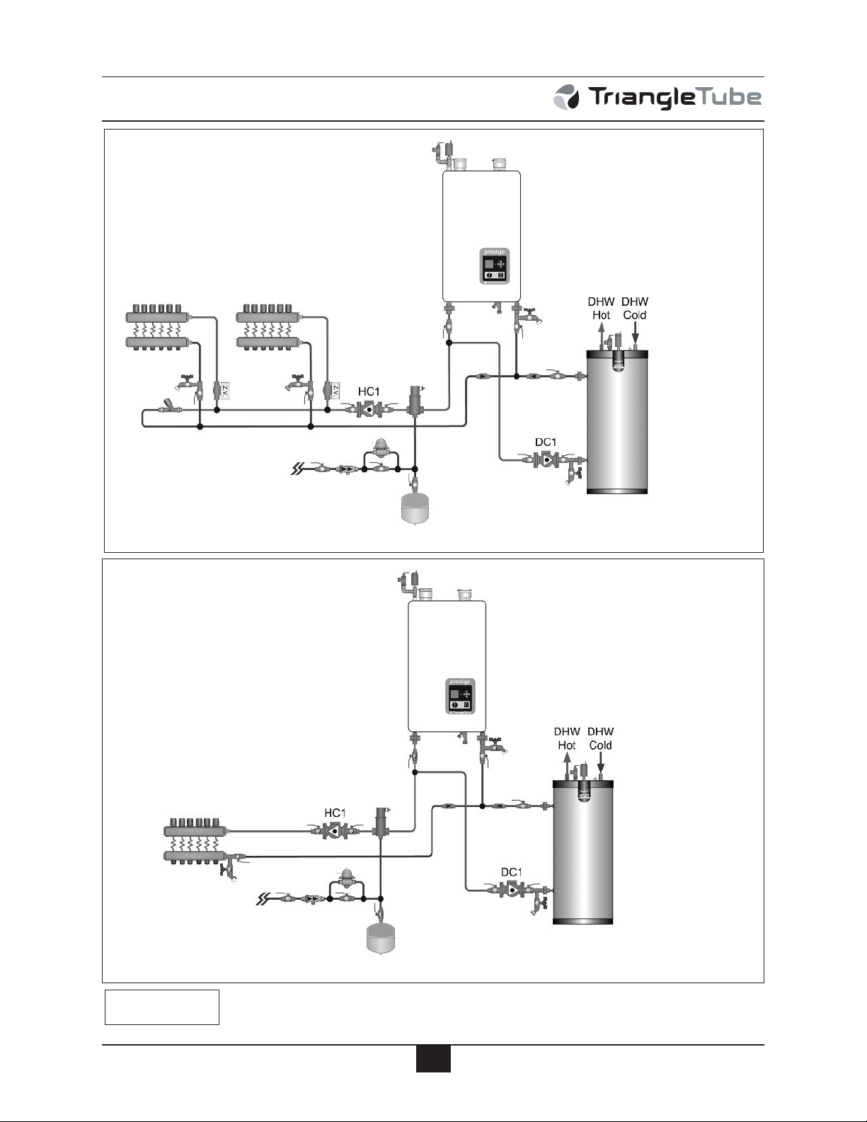
Figure 11, page 22 illustrates a multiple zone
valve system with a single system/boiler circulator. A by-pass loop with a pressure differential
valve must be installed on the system piping.
Figure 12, page 22 illustrates a single zone utilizing the boiler circulator as the system circulator.
System Piping - Radiant Heating
The heat exchanger design of the PRESTIGE
allows operation in a condensing mode. This
feature requires no regulation of the return
temperature back to the boiler in radiant heating applications.
The design and construction of the PRESTIGE
heat exchanger allows the installation of the boiler on systems with non - oxygen barrier tubing.
NOTICE
To ensure an adequate flow rate through
the PRESTIGE Solo, the boiler supply
and return piping size must be a minimum of 1 inch for the PRESTIGE Solo 60,
1-1/4 inch for the PRESTIGE Solo
175/250 and 1-1/2 inch for the PRESTIGE
Solo 399.
NOTICE
The addition of the high temperature limit
is important if the PRESTIGE is connected to a domestic hot water system, which
requires a high primary supply water
temperature.
System Piping - Special Application
If the boiler is used in conjunction with a
chilled water/medium system, the boiler and
chiller must be piped in parallel. Install
flow/check valves to prevent the chilled medium from entering into the boiler.
CAUTION
DO NOT install a SMART tank along
with the PRESTIGE in systems with
non-oxygen barrier tubing. Failure to
comply could result in premature failure
of the SMART tank.
The boiler water supply temperature can be
maintained by the PRESTIGE, eliminating
the need for a mix system to achieve the
desired temperature.
It is recommended for the installer to install a
high temperature limit to ensure that the primary supply temperature does not exceed the
maximum allowable temperature for the radiant tubing.
Size the system piping and circulator to provide the flow needed for the radiant system.
If the boiler is used to supply hot water to the
heating coils of an air handler where they may
be exposed to chilled air circulation, install
flow/check valves or other automatic means
to prevent gravity circulation of the boiler
water during cooling cycles.
System Piping - Multiple Units Installation
Use a balanced manifold system as the primary / secondary connection to the space heating
piping as shown in Fig. 13 page 23.
Maintain a minimum of 6 inches [153 mm] of
clearance between units to allow for servicing.
For the space heating piping refer to the applications mentioned in this manual or use recognized design methods.
20
Page 27
Boiler Piping
Note: Reference Fig. 23, page 38 for
Prestige Wiring.
Fig. 9: System Piping - Zoning with Zone Circulators
Note: Reference Fig. 24, page 38 for
Prestige Wiring.
Fig. 10: System Piping - Zoning with Zone Valves
NOTICE
The boiler system piping shown must be a “closed” system to avoid any
oxygen contamination and potential failure of the outer tank of the Smart.
21
Page 28
Boiler Piping
Note: Reference Fig. 25, page 39 for
Prestige Wiring.
Note: Verify CH circulator is
properly sized to overcome the
system pressure drop and provide adequate flow through the
boiler system.
Fig. 11: System Piping - Multiple Zone Valve with Single System/Boiler Circulator
Note: Reference Fig. 26, page 39 for
Prestige Wiring.
Note: Verify CH circulator is properly sized to
overcome the system pressure drop and provide adequate flow through the
boiler system.
Fig. 12: System Piping - Single Zone System with Single System/Boiler Circulator
NOTICE
The boiler system piping shown must be a “closed” system to avoid any
oxygen contamination and potential failure of the outer tank of the Smart.
22
Page 29
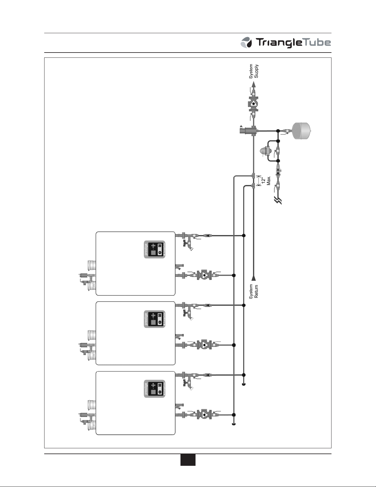
Boiler Piping
Note: Consult the PRESTIGE
TriMax Control Supplement for
information on wiring and con-
figuring the boilers using the
built-in Cascade function
23
Fig. 13: Multiple PRESTIGE Solo Boiler Piping - Primary / Secondary
Page 30
Installing Vent/Combustion Air & Condensate Drain
SECTION V - Installing Vent /
Combustion Air & Condensate Drain
Installing Vent and Combustion Air
DANGER
The PRESTIGE Solo must be vented
and supplied with combustion air as
shown in the PRESTIGE Solo Vent
Supplement, included in the boiler
installation envelope. Refer to optional
vent kit instructions for additional vent
installation instructions. Once installation is completed, inspect the vent and
combustion air system thoroughly to
ensure systems are airtight and comply
with the instructions given in the venting
supplement and are within all requirements of applicable codes. Failure to
comply with the installation requirements on the venting and combustion air
piping will cause severe personal injury
or death.
WARNING
Ensure the condensate drain assembly
contains the plastic seated ball. Do not
install the condensate drain assembly if
the ball is lost or missing, replace the
entire assembly.
3. Remove the compression nut and rubber
seal from the drain outlet.
4. Using 3/4” x 2’ flexible PVC tube provided, slide the compression nut and rubber
seal over the pipe
NOTICE
The use of 3/4” PVC or CPVC pipe is
also acceptable. If 3/4” pipe is used
deburr and chamfer pipe to allow mating onto the drain assembly.
5. Thread the rubber seal into the compression nut to ease installation of the pipe to
the drain assembly.
Installing Condensate Drain Assembly
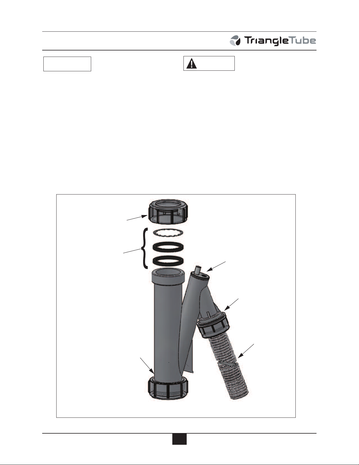
1. Locate the condensate drain assembly and
install as shown in Fig. 14 page 25.
NOTICE
The installer may want to fill the condensate trap with water prior to assembling on the unit.
2. Remove the retaining nut, metal washer
and rubber seals from the condensate drain
assembly and slide over the heat exchanger
condensate drain nipple. Make sure to
place the metal washer on top of the rubber
seals. Connect the condensate drain assembly to the retaining nut and tighten. Hand
tight only!
6. Seat the pipe onto the drain assembly and
tighten the compression nut. Hand tight
only!
NOTICE
The installer may opt to using 13/16" ID
tubing in lieu of rigid piping.
NOTICE
The drain line materials must be an
approved material by the authority having jurisdiction. In absence of such
authority, PVC and CPVC piping must
comply with ASTM D1785 or D2845.
The cement and primer used on the piping must comply with ASME D2564 or
F493. For installations in Canada, use
CSA or ULC certified PVC or CPVC
pipe, fittings and cement/primer.
7. Continue the pipe from the drain assembly
to a floor drain or condensate pump.
24
Page 31
Installing Vent/Combustion Air & Condensate Drain
Flexible Tubing
(or 3/4 PVC/
CPVC Piping
to Drain)
Compression
Nut with Rubber Seal
Fill Plug
with Vaccum
Break Port
Condensate
Drain Assembly
Retaining Nut
(Hand Tight Only)
Place the Metal Washer
and (2) Rubber Gaskets
in this Order for Proper
Seal.
NOTICE
When selecting and installing a condensate pump, ensure the pump is approved
for use with condensing boilers and furnaces. The pump should be equipped
with an overflow switch to prevent property damage from potential condensate
spillage.
8. The PRESTIGE Solo will typically produce
a condensate that is considered slightly
acidic with a pH content below 3.0. Install
a neutralizing filter if required by authority
having jurisdiction.
CAUTION
The condensate drain must remain filled
and unobstructed and allow unrestricted
flow of condensate. The condensate
should not be subject to conditions
where freezing could occur. If the condensate is subjected to freezing or
becomes obstructed , it can leak, resulting in potential water damage to the boiler and surrounding area.
Fig. 14: Condensate Drain Assembly
25
Page 32
Gas Piping
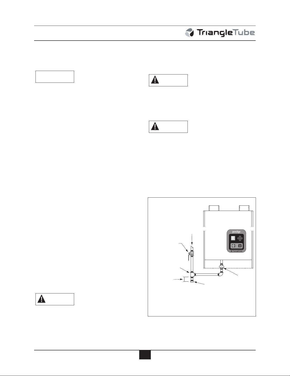
Sediment
Trap Min.
Length of 3"
Union Fitting
Cap
Tee Fitting
External Manual
Gas Shut Off
Valve (Must Be
Within 6' of the
Boiler)
Gas Flow
SECTION VI - Gas Piping
Gas Supply Piping Connection
NOTICE
The gas supply piping must be installed
in accordance to all applicable local,
state and national codes and utility
requirements.
1. Install a 1/2” NPT for PRESTIGE Solo 60,
3/4” NPT for PRESTIGE Solo 175/250 or
1” NPT for PRESTIGE Solo 399 pipe
union at the factory supplied gas nipple, for
ease of service.
2. Install a manual shutoff valve in the gas
supply piping as shown in Fig. 15. For
installations in Canada the installer must
tag and identify the main shutoff valve.
3. Install a sediment trap (drip leg) on the gas
supply line prior to connecting to the PRESTIGE Solo gas train as shown in Fig. 15.
7. Use pipe dope compatible with natural and
propane gases. Apply sparingly only to the
male threads of pipe joints so that pipe
dope does not block gas flow.
WARNING
Failure to apply pipe dope as detailed
above can result in severe personal
injury, death or substantial property
damage.
WARNING
Use a two-wrench method of tightening
gas piping near the unit and its gas piping connection. Use one wrench to prevent the boiler gas line connection from
turning and the second to tighten adjacent piping. Failure to support the boiler gas piping connection could damage
the gas line components.
4. Support the gas piping using hangers. Do
not support the piping by the unit or its
components.
5. Purge all air from the gas supply piping.
6. Before placing the PRESTIGE Solo into
operation, check and test all connections
for leaks.
- Close the manual shutoff valve during
any pressure test with less than 13”w.c..
- Disconnect the PRESTIGE Solo and its
gas valve from the gas supply piping
during any pressure test greater than
13”w.c..
WARNING
Do not check for gas leaks with an open
flame. Use a gas detection device or bubble test. Failure to check for gas leaks
can cause severe personal injury, death
or substantial property damage.
Fig. 15: Recommended Gas Supply Piping
26
Page 33
Gas Piping
NATURAL GAS
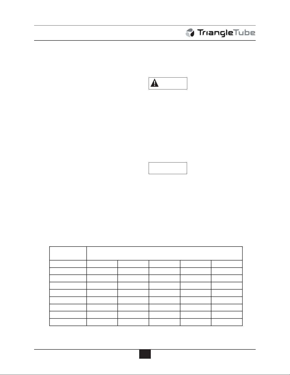
Pipe Sizing - Natural Gas
Refer to Table 1 for schedule 40 metallic pipe
length and diameter requirements for natural
gas, based on rated PRESTIGE Solo input
(divide by 1,000 to obtain cubic feet per hour).
- Table 1 is based on Natural Gas with a specific gravity of 0.60 and a pressure drop
through the gas piping of 0.30”w.c..
- For additional gas piping sizing information, refer to ANSI Z223.1. For Canadian
installations refer to B149.1 or B149.2.
Natural Gas Supply Pressure Requirements
1. Pressure required at the gas valve inlet
supply pressure port:
- Maximum 13”w.c. at flow or no flow
conditions to the burner.
- Minimum 5”w.c. during flow conditions
to the burner. Must be verified during
start up and with all other gas appliances
operating within the building.
2. Install 100% lockup gas pressure regulator
in the gas supply line if inlet pressure can
exceed 13”w.c at any time. Adjust the lockup pressure regulator for 13”w.c maximum.
WARNING
DO NOT adjust or attempt to measure
gas valve outlet pressure. The gas valve
is factory-set for the correct outlet pressure. This setting is suitable for natural
gas and propane and requires no field
adjustment. Attempts by the installer to
adjust or measure the gas valve outlet
pressure could result in damage to the
valve, causing potential severe personal
injury, death or substantial property
damage.
NOTICE
The natural gas orifice requirements are:
PRESTIGE Solo 60: 0.204” (5.2 mm)
PRESTIGE Solo 175: None Required
PRESTIGE Solo 250: None Required
PRESTIGE Solo 399: 0.339” (8.6 mm)
Table 1: Gas Piping Sizing - Natural Gas
Length of Pipe in
Feet
SCH 40 1/2" 3/4" 1" 1-1/4" 1-1/2"
10 132 278 520 1050 1600
20 92 190 350 730 1100
30 73 152 285 590 890
40 63 130 245 500 760
50 56 115 215 440 670
75 45 93 175 360 545
100 38 79 150 305 460
150 31 64 120 250 380
Capacity of Schedule 40 Metallic Pipe in Cubic Feet of Natural Gas Per
Hour (based on 0.60 specific gravity, 0.30" w.c. pressure drop)
27
Page 34
Gas Piping
PROPANE GAS
Pipe Sizing - Propane Gas
Contact the local propane gas supplier for recommended sizing of piping, tanks and 100%
lockup gas regulator.
Propane Gas Supply Pressure Requirements
1. Adjust the propane supply regulator provided by the gas supplier for 13”w.c. maximum pressure
2. Pressure required at the gas valve inlet supply pressure port:
- Maximum 13”w.c. at flow or no flow
conditions to the burner
- Minimum 5”w.c. during flow conditions
to the burner. Must be verified during
start up and with all other gas appliances
operating within the building.
WARNING
Prior to start up, ensure the unit is set to
fire propane. Check the rating label for
the type of fuel. Check the gas valve for
propane conversion label. If there is a
conflict or doubt on the burner set up,
remove the gas valve and check for the
propane orifice, see Fig. 16 or 17, page
29. Failure to ensure proper burner
setup could result in severe personal
injury, death or substantial property
damage.
NOTICE
The propane orifice requirements are:
PRESTIGE Solo 60: 0.120” (3.1 mm)
PRESTIGE Solo 175: 0.221” (5.6 mm)
PRESTIGE Solo 250: 0.250” (6.3 mm)
PRESTIGE Solo 399: 0.264” (6.7 mm)
WARNING
DO NOT adjust or attempt to measure
gas valve outlet pressure. The gas valve
is factory-set for the correct outlet pressure. This setting is suitable for natural
gas and propane and requires no field
adjustment. Attempts by the installer to
adjust or measure the gas valve outlet
pressure could result in damage to the
valve, causing potential severe personal
injury, death or substantial property
damage.
28
Page 35
Gas Piping
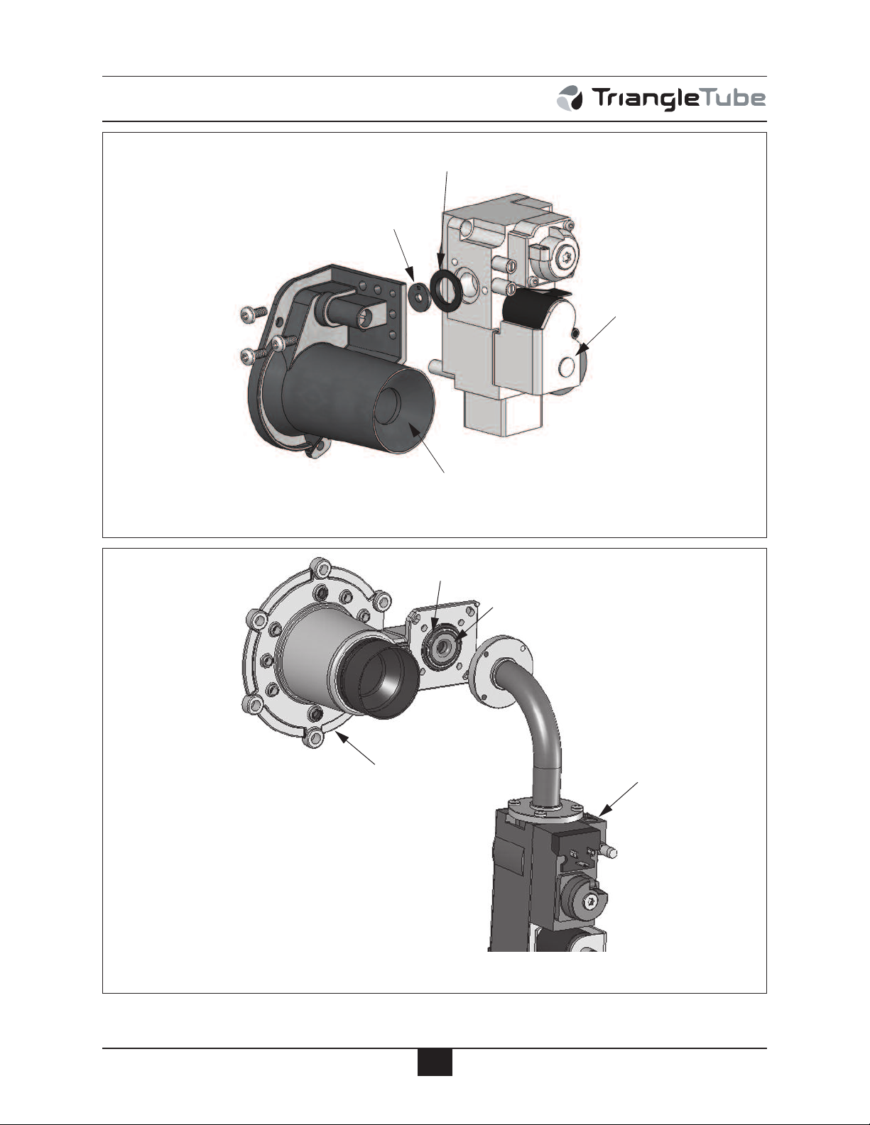
Gas Valve
Orifice
Gaskets
Venturi
Venturi
Orifice
Gas Valve
Gasket
Gas Valve
Fig. 16: Gas Valve / Venturi Assembly - PRESTIGE Solo 60/175/250
Fig. 17: Gas Valve / Venturi Assembly - PRESTIGE Solo 399
29
Page 36
Internal Wiring
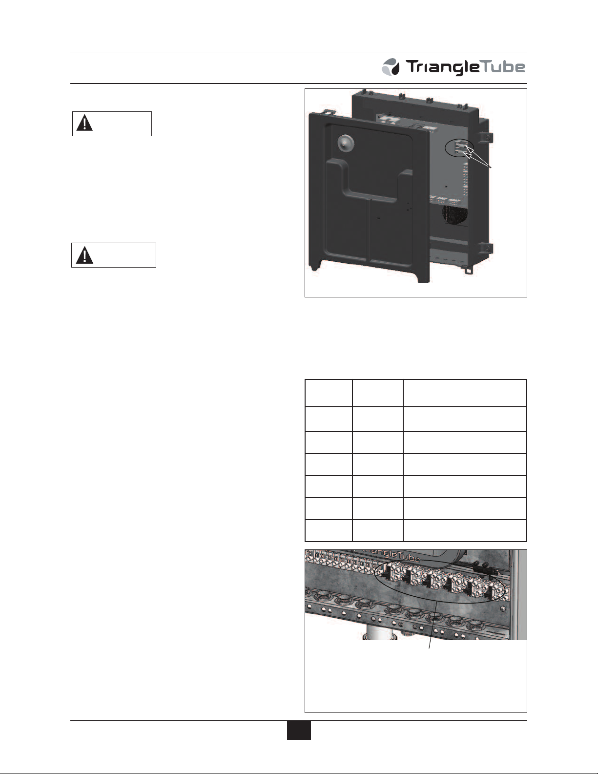
Location
of Fuses
TriMax Line Voltage
Fuse Location
SECTION VII - Internal Wiring
WARNING
ELECTRICAL SHOCK HAZARD. For
your safety, disconnect electrical power
supply to the unit before servicing or
making any electrical connections to
avoid possible electric shock hazard.
Failure to do so can cause severe personal injury or death.
CAUTION
Prior to servicing, label all wires before
disconnecting. Wiring errors can cause
improper and dangerous operation.
Verify proper wiring and operation after
servicing.
General Requirements
- Wiring must be N.E.C Class 1.
Fig. 18: TriMax Control Module Fuse Location
Additional fuses are also located on the line
voltage terminals as shown in Fig. 18A and
Fig. 19.
TriMax Line Voltage Fuses
- If original wiring as supplied with the unit
must be replaced, use only Type T 194ºF
[90ºC] wire or equivalent as a minimum.
- The PRESTIGE must be electrically
grounded as required by National
Electrical Code ANSI/NFPA 70 - latest edition and / or the Canadian Electrical Code
Part 1, CSA C22.1, Electrical Code.
Fuse Locations
The TriMax control module contains 2 internal
replaceable 5A fuses as shown in Figure 18.
Fuse Size Terminals Purpose
2.5A 23,24,25 CH2 /System Pump
2.5A 26,27,28 Auxiliary Boiler Pump
2.5A 29,30,31 DHW Pump / Diverter Valve
2.5A 32,33,34 CH1 Pump/Diverter Valve
8.0A 35,36,37 Power Supply
2.5A 38,39,40 Alarm
Fig. 18A: Fuse Location on the line voltage Terminals
30
Page 37
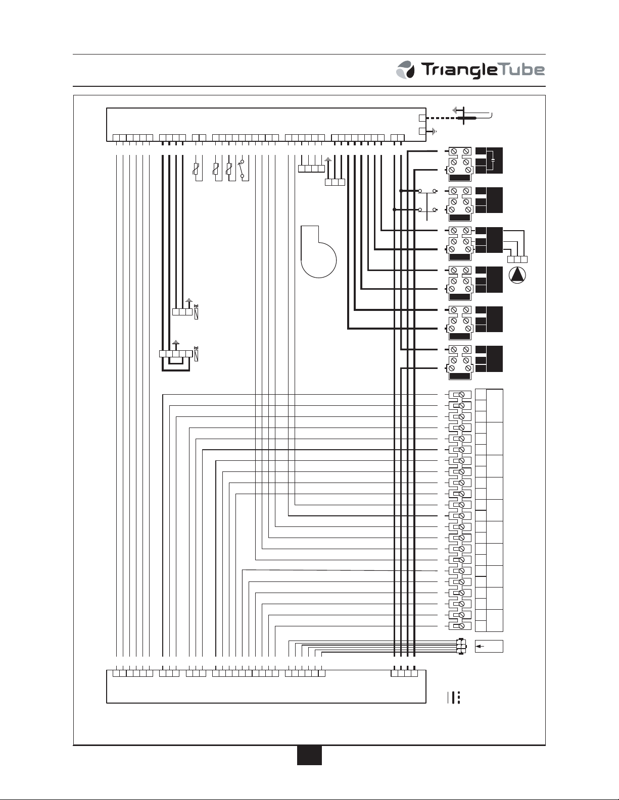
Internal Wiring
1 2
CH1
Thermostat
3 4
CH2
Thermostat
5 6
Outdoor
Sensor
7 8
DHW
Aquastat
or Sensor
9 10
Manual
Reset
Limit
11 12
Auto
Reset
Limit
13 14
+ -
Modulation
Signal
15 16
System
Sensor
17 18 19
Cascade
Master
20 21 22
A B G
Modbus
25
L G N
CH2 Pump /
System Pump
23 24
37
L G N
Power Supply
35 36 40
Alarm
38 39
Cascade
Slave
31*
L G N
DHW Pump /
*Diverter Valve
29* 30
Circulator Terminals
28
L G N
Auxiliary
Boiler Pump
26 27
Circulator factory
wired on Prestige
Solo 110 only.
14711
428125136
5
1
65432
1
G
N
L
X00
X01
X11
X13
X14
X02
X15
TriMax
Control
Module
On / Off
Switch
65432
1
3291054168
7
6
3
1
4
18732
9
X03
X04
X07
X05
X01
TriMax
Display
Module
543
X06
2
94837
2105
71268
3
2
1
3
2
563
4
Flue Temperature Sensor
Supply Temperature Sensor
Return Temperature Sensor
LWCO
BKBKBK
BK
BK BK BK BK W W V V BR BR O O BL BL R R W W W BR Y GY BK BK BK BK BK RW W W W W R
WWWWW
W
W
W
V
V
BR
BR
O
O
BL
BL
R
R
WWW
BR
Y
GY
YYYYY
Y
R
R
BK
BK
BK
R
BL
WBKWBKWBKWBKWBKW
O
BL
BL
R
R
Y
Y
WBKW
BK
YYYYY
Y
O
124
5
321
Blower
Power Terminals
Blower
Blower
Signal Terminals
GND
5
Gas Valve
(All except Solo 399)
V1
V1GV2
V2
GND
Gas Valve
(Solo 399 only)
1
3
GND
F00
GND
GND
Ignitor
Notes:
1. If any of the original wire supplied with the appliance must be replaced, it must be replaced with the same
type or its equivalent.
2. All 120 VAC field wiring to the boiler shall have a minimum size of 14 AWG with a temperature rating of at
least 194°F [90°C].
Wire Legend
- Low Voltage
- Line Voltage
- Ignition Cable
Wire Color Legend
BK – Black
W – White
GR – Green
BL – Blue
R – Red
O – Orange
V – Violet
Y – Yellow
BR – Brown
GY - Gray
Prestige Solo Internal Wiring
34
L G N
CH (1) Pump /
*Diverter Valve
32* 33
Fig. 19: Prestige Solo Boiler Factory Wiring
31
Page 38
External Wiring
SECTION VIII- External Wiring
Installation Compliance
All field wiring made during installation must
comply with:
- National Electrical Code NFPA 70 and any
other national, state, provincial or local
codes or requirements.
- In Canada, CSA C22.1 Canadian Electrical
Code Part 1, and any other local codes.
WARNING
ELECTRICAL SHOCK HAZARD.
Before making any electrical connections to the PRESTIGE, disconnect electrical power supply at the service panel.
Failure to comply can cause severe personal injury or death.
Circulator Wiring
1. Reference Table 2 to determine the appropriate circulator connections required. The
circulator connections used will depend on
the systems piping layout.
Table2: Circulator Operation Default Setting
Auxillary
Boiler
Pump
ON ON
System
Pump
OFF
(Note 2)
CH 1 or
CH 2 Call
DHW Call
CH (1)
Pump
ON
OFF
(Note 1)
DHW
Pump
OFF
(Note 1)
ON ON
Note 1: Domestic Hot Water Priority can be
disabled in the Installer Menu
which allows the CH (1) and DHW
circulators to operate at the same
time. Consult the PRESTIGE
TriMax Control Supplement for
more information.
NOTICE
The line voltage terminals are located on
the right set of terminals 23 through 40.
The low voltage terminals are located on
the left set of terminals 1 through 22.
Line Voltage Connections
1. Connect a dedicated 120 VAC/15A service
to the line voltage terminal strip on the
wiring panel below the PRESTIGE control
module, as shown in Fig. 19, page 31.
2. Route the incoming 120 VAC power wire
through the provided openings in the bottom jacket panel.
3. The unit is provided with a service switch
located on the front panel, check local code
requirements for compliance.
NOTICE
If local electrical codes or conditions
require an additional service switch, the
installer must provide and install a fused
disconnect or 15 amp (minimum) service
switch.
Note 2: The system circulator can also be
enabled during a DHW Call in the
Installer Menu. Consult the PRESTIGE TriMax Control Supplement for
more information.
NOTICE
Each circulator is individually fused with a
2.5A fuse located in the terminal strip. The
total combined amp draw of the CH (1),
DHW, and Auxiliary Boiler Circulators
must not exceed 4 amps at any time for the
Solo 60, 175, or 250. The total combined
amp draw of the CH (1), DHW, and
Auxiliary Boiler Circulators must not
exceed 3 amps at any time for the Solo 399.
Use an isolation relay to lower the total combined amp draw if exceeding these limits.
2. Connect the CH circulator to the line voltage terminal strip on the wiring panel
below the PRESTIGE control module, as
shown in Fig. 19 on page 31. The CH circulator is enabled during a CH 1 or CH 2
call. This circulator is used to supply heat
to the central/space heating loop.
32
Page 39
External Wiring
3. Connect the DHW circulator to the line
voltage terminal strip on the wiring panel
below the PRESTIGE control module, as
shown in Fig. 19 on page 31. The DHW
circulator is enabled during a DHW call.
This circulator is used to supply heat to an
indirect hot water heater.
4. Connect the Auxiliary Boiler circulator to
the line voltage terminal strip on the wiring
panel below the PRESTIGE control module, as shown in Fig. 19 on page 31. The
auxiliary boiler circulator is enabled during
a CH or a DHW call. This circulator is typically used in retrofit applications where
the CH and DHW systems are connected to
a common boiler supply.
5. Connect the System circulator to the line
voltage terminal strip on the wiring panel
below the PRESTIGE control module, as
shown in Fig. 19 on page 31. The system
circulator is enabled during a CH1 or CH2
call with the factory default TriMax settings. This circulator is typically used to
circulate water in the secondary CH loop
when zoning with zone valves.
Low Voltage Connections
NOTICE
Line and Low Voltage wiring should be
separated to prevent possible electrical
noise on the low voltage circuits. Line
and Low Voltage wiring should use separate electrical knockouts on the PRESTIGE cabinet and should remain separated inside the PRESTIGE.
NOTICE
CH and DHW call connections to the
PRESTIGE require a dry contact with no
external voltage present. Ensure no external voltage is present on each set of wires
before connecting to the PRESTIGE. If
external voltage is present, the use of an
isolation relay is required to prevent damage to the TriMax controller.
Thermostat Wiring
Alarm Wiring
The alarm contact closes whenever the
Prestige is in a soft or hard lockout. This
dry contact can be connected to an external
monitoring system or other indicator to alert
the operator that the Prestige is locked out.
1. Connect the external monitoring device to
the line voltage terminal strip on the wiring
panel below the PRESTIGE control module, as shown in Fig. 19 on page 31.
NOTICE
The alarm contact is fused with a 2.5A
fuse located in the terminal strip. An isolation relay is required if the external
monitoring device draws more than 2.5A.
The TriMax control has two thermostat call inputs
for multiple zone / temperature systems. This
allows each call to have its own outdoor reset
curve and maximizes the efficiency of the system.
WARNING
Simultaneous CH1 and CH2 calls will
result in the PRESTIGE operating at the
highest target temperature. The use of a
mixing device on the lower temperature
zones such as the Triangle Tube Optima
Series SMV Control may be required to
protect the lower temperature zones
from damage.
1. Connect the room thermostat or dry contact
end switch to the low voltage terminal strip
on the wiring panel below the PRESTIGE
control module, as shown in Fig. 19 on
page 31.
33
Page 40

External Wiring
2. Follow thermostat manufacturer’s instructions for proper installation. Thermostat
should be located on an inside wall away
from any heat or cold influences such as
drafts, lights, fireplaces, etc.
3. Set the thermostat anticipator (If applicable) as follows:
- Set for 0.2 amps when wired directly to
the PRESTIGE.
- Set to match the electrical power
requirements of the connected device
when wired to zone relays or other
devices. Refer to the relay manufacturer’s specifications and the thermostat
instructions for additional information
on anticipator setting.
NOTICE
The use of power stealing thermostats
which draw their power from the PRESTIGE can lead to erratic or unpredictable operation. Honeywell T87 series
thermostats are excluded from this
notice since they are designed to operate
with the TriMax control.
Additional Boiler Limits
Additional boiler limits (High Limit, LWCO,
etc.) can be wired into either the Manual Reset
Limit or Auto Reset Limit terminals of the
PRESTIGE. These limit connections will provide a “hard” lockout requiring a manual reset
of the PRESTIGE or a “soft” lockout in which
the PRESTIGE will automatically reset when
the limit resets.
NOTICE
Manual Reset Limit and Auto Reset
Limit connections to the PRESTIGE
require a dry contact with no external
voltage present. Ensure no external voltage is present on each set of wires before
connecting to the PRESTIGE. If external voltage is present, the use of an isolation relay is required to prevent damage
to the TriMax controller.
1. Remove the factory installed jumper wire
on the Manual Reset or Auto Reset terminals that will accept the additional boiler
limit.
Outdoor Sensor Wiring
The Outdoor Reset function and Warm
Weather Shutdown (WWSD) features require
the connection of the included outdoor temperature sensor. See page 63 for outdoor sensor
installation and setup.
Domestic Hot Water Wiring
The Domestic Hot Water terminals can accept
either a call from an aquastat (switch) or temperature sensor. Use of the included indirect
water heater sensor is recommended.
1. Connect the DHW aquastat or temperature
sensor to the low voltage terminal strip on
the wiring panel below the PRESTIGE control module, as shown in Fig. 19 on page 31.
2. Connect the additional boiler limit to the
low voltage terminal strip on the wiring
panel below the PRESTIGE control module, as shown in Fig. 19 on page 31.
External Modulation Control
The PRESTIGE firing rate can be controlled by
an external modulating boiler controller. See
page 64 for external modulation signal wiring
and setup.
System Sensor Wiring
An optional system temperature sensor can be
placed on the central heating loop to control the
temperature in the central heating loop instead
of the boiler loop. When connected, the PRESTIGE will automatically modulate to maintain
the target temperature in the central heating
loop. The boiler supply temperature sensor
will continue to be used as a high temperature
limit.
34
Page 41

External Wiring
CAUTION
Locate the system temperature sensor
where it can accurately measure the supply temperature to the heating system.
Inaccurate system temperature readings
could lead to overheating or under heating resulting in property damage.
Cascade Wiring
The TriMax control includes the ability to
operate up to six boilers together as one without the need for external controllers. Consult
the PRESTIGE TriMax Control Supplement
for more information.
Modbus Wiring
1. Connect the system temperature sensor to
the low voltage terminal strip on the wiring
panel below the PRESTIGE control module, as shown in Fig. 19 on page 31.
The TriMax control includes the ability to
communicate with building management systems (BMS) through a Modbus interface.
Consult the PRESTIGE TriMax Control
Supplement for more information.
35
Page 42
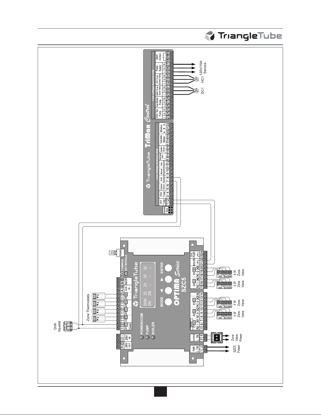
External Wiring
Fig. 20: Multiple Zone Field Wiring Using Zone Valves
36
Page 43
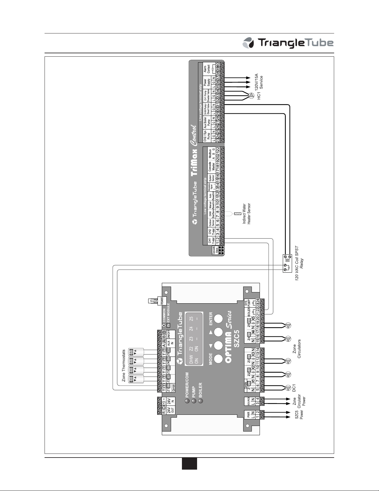
External Wiring
Fig. 21: Multiple Zone Field Wiring using Zone Circulators
37
Page 44
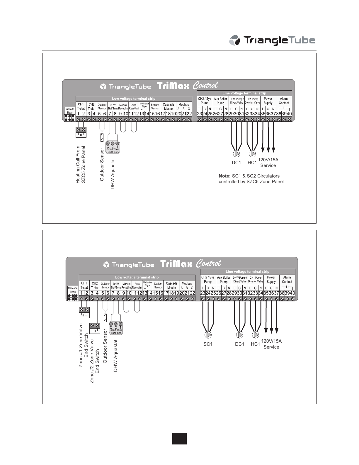
External Wiring
Note: Reference Fig. 9, page 21 for
System Piping.
Fig. 23: Prestige Wiring - Zoning with Zone Circulators
Note: Reference Fig. 10, page 21 for
System Piping.
Fig. 24: Prestige Wiring - Zoning with Zone Valves
38
Page 45
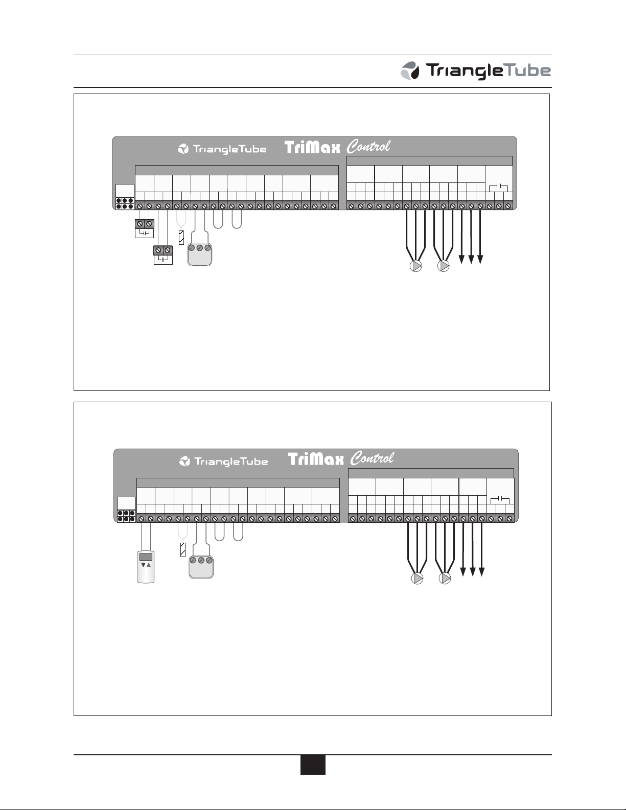
External Wiring
DHW Aquastat
Outdoor Sensor
Zone #2 Zone Valve
End Switch
Zone #1 Zone Valve
End Switch
DC1
HC1
120V/15A
Service
C21
Smart Tank
Snap Set
CH1
T-stat
5
Low voltage terminal strip
Cascade
Slave
CH2
T-stat
Outdoor
Sensor
DHW
Stat/Sens
Manual
Reset/lmt
Auto
Reset/lmt
Modulation
Signal
+ -
System
Sensor
Cascade
Master
Modbus
A B G
CH2 / Sys
Pump
L G N
Aux Boiler
Pump
L G N
DHW Pump /
Divert Valve
L G N
CH1 Pump
Diverter Valve
L G N
Power
Supply
L G N
Alarm
Contact
Line voltage terminal strip
1 2 34 6 7 8 910111213141516171819202122 232425262728293031323334353637383940
DHW Aquastat
Outdoor Sensor
Room Thermostat
DC1
HC1
120V/15A
Service
C21
Smart Tank
Snap Set
CH1
T-stat
5
Low voltage terminal strip
Cascade
Slave
CH2
T-stat
Outdoor
Sensor
DHW
Stat/Sens
Manual
Reset/lmt
Auto
Reset/lmt
Modulation
Signal
+ -
System
Sensor
Cascade
Master
Modbus
A B G
CH2 / Sys
Pump
L G N
Aux Boiler
Pump
L G N
DHW Pump /
Divert Valve
L G N
CH1 Pump
Diverter Valve
L G N
Power
Supply
L G N
Alarm
Contact
Line voltage terminal strip
1 2 34 6 7 8 910111213141516171819202122 232425262728293031323334353637383940
68
Note: Reference Fig. 11, page 22 for
System Piping.
Fig. 25: Prestige Wiring - Multiple Zone Valve with Single System/Boiler Circulator
Note: Reference Fig. 12, page 22 for
System Piping.
Fig. 26: Prestige Wiring - Single Zone System with Single System/Boiler Circulator
39
Page 46
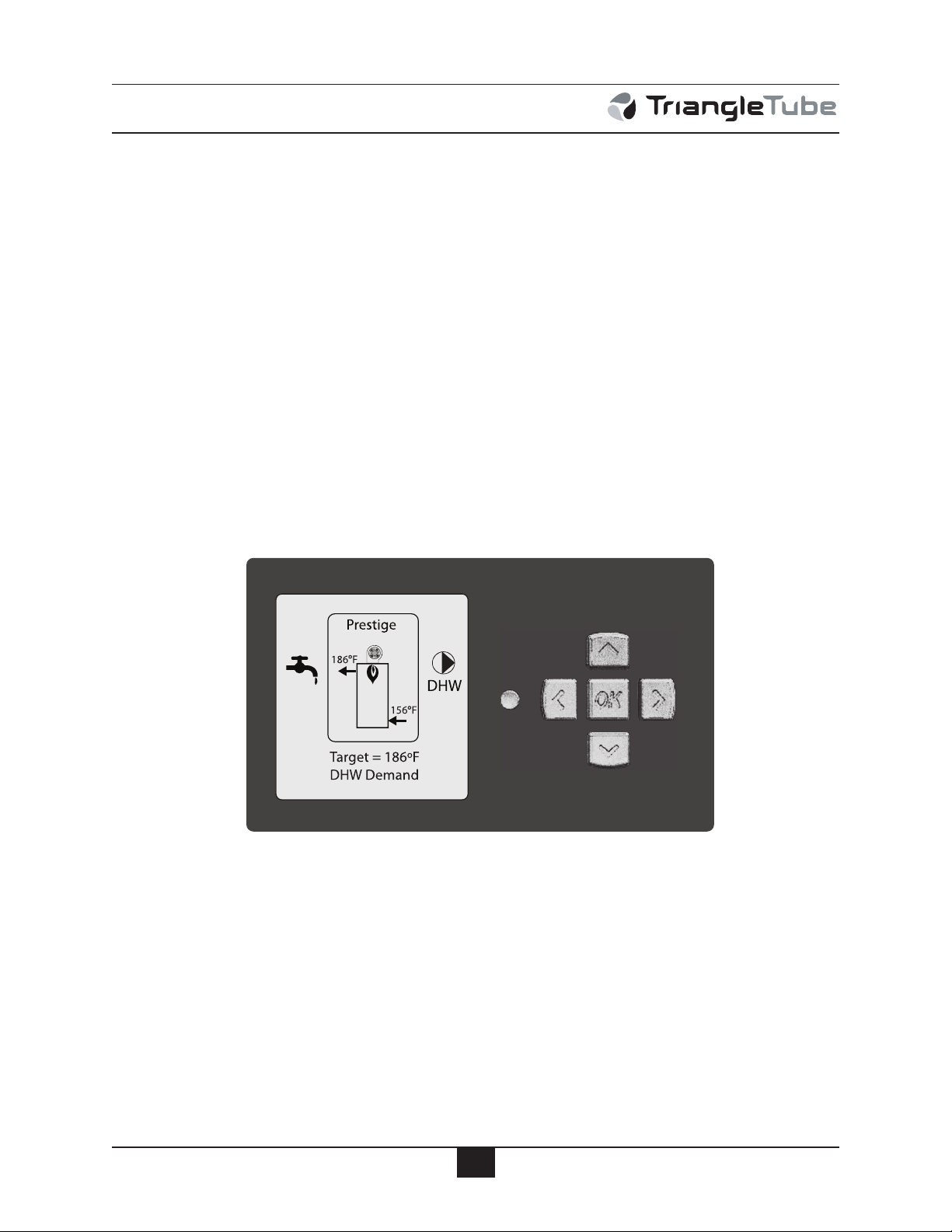
TriMax Operation
SECTION IX- TriMax Operation
The TriMax Boiler Management System is designed to be flexible yet easy to use. TriMax monitors and controls the Prestige to provide heat as efficiently as possible. TriMax includes many
advanced features which previously were not available in the Prestige.
• Two central/space heating (CH) call inputs with separate outdoor reset curves.
• Domestic Hot Water (DHW) call input with optional priority.
• EZ Setup feature allows the installer to quickly customize TriMax for each installation.
• Cascade function allows up to six Prestige boilers to operate together in a single heating system.
• Modbus interface for integrating with building management systems.
All TriMax features are easy to use through a graphical display where information is presented
either graphically or in plain English, so code charts are not required. Figure 30 shows a TriMax
display example of the Prestige fired for a domestic hot water demand.
Fig. 30: TriMax User Interface
40
Page 47
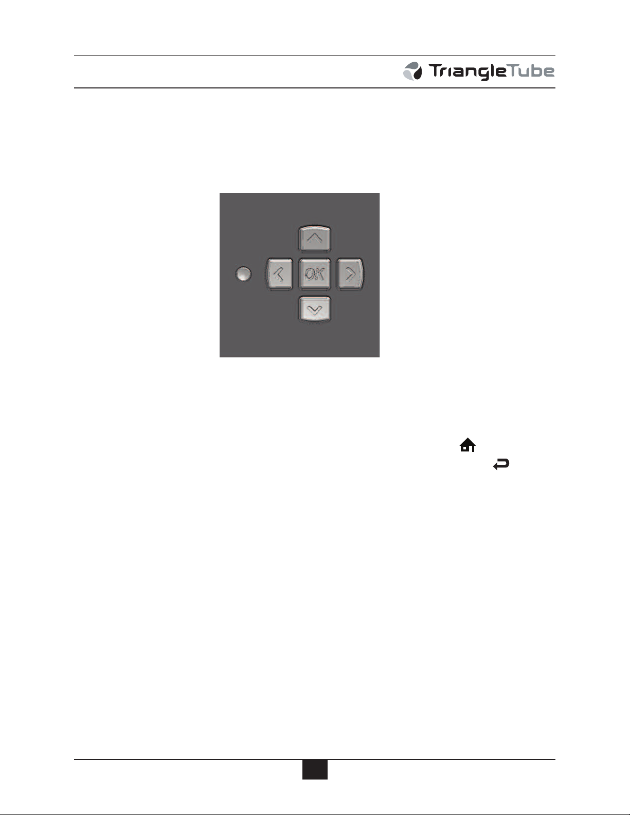
TriMax Operation
TriMax Navigation
Navigation is performed through four arrow buttons UP, DOWN, LEFT, RIGHT with a center
OK button for making selections and entering information. The INSTALLER button (the small
round button) provides the installing contractor with full access to all available features after
entering a password. Reference the TriMax Control Supplement for Installer level functions.
Figure 31 – TriMax Navigation Buttons
The Main Menu can be entered from the Home Screen by pressing the OK button. The menu
system utilizes icons to represent each selection. The current selected menu is displayed as a
reversed image with a text description shown at the top of the display. Menus can be entered by
highlighting the desired icon and pressing the OK button. The Home Screen icon at the bottom of each screen returns to the Home Screen when selected. The Previous Screen icon at
the bottom of each screen returns to the previous screen when selected.
41
Page 48
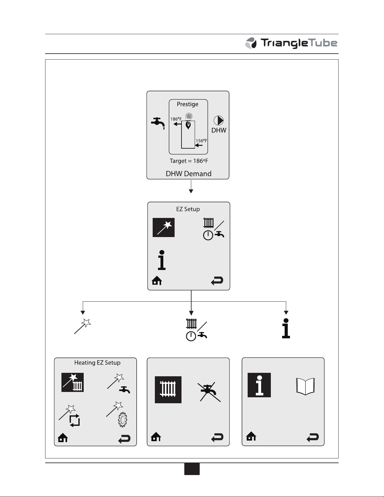
TriMax Operation
a
b
c
d
e
f
b
b
b
b
a
b
c
d
e
f
b
b
a
b
c
d
e
a
b
c
d
e
f
b
b
b
b
a
b
c
d
e
f
b
b
a
b
c
d
a
b
c
d
e
f
b
b
b
b
a
b
c
d
e
f
b
b
a
b
c
d
e
a
b
c
d
e
f
b
b
b
b
a
b
c
d
e
f
b
b
f
b
g
a
b
c
d
Boiler Information
Boiler Information MenuCH/DHW Operation Menu
EZ Setup Menu
Main Menu
Home Screen
Heating Enabled
TriMax Menu Structure
42
Page 49
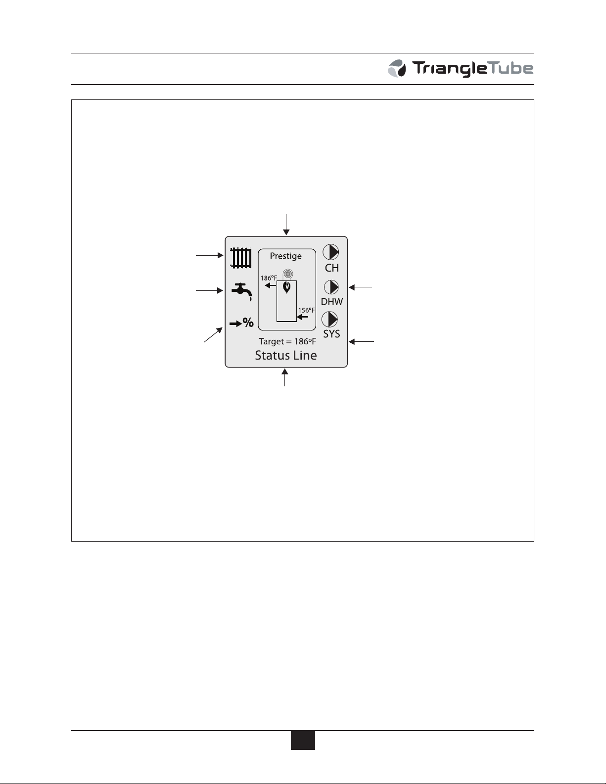
TriMax Operation
The status line displays the current operating state of the Prestige.
See page 44 for a list of all Status Line Messages.
The radiator icon indicates that a
central heating call has been received.
A small number 1 or 2 indicates
which CH calls are active.
Circulator icons indicate which
circulators are currently powered.
The faucet icon indicates that a
domestic hot water call has been
received.
The percentage icon indicates that
an external modulation call has
been received.
This line provides basic information.
The user can press the LEFT or RIGHT
arrow buttons to view Target, Supply,
Return, Domestic and Outdoor
Temperatures.
The Prestige is represented in the center of the Home Screen. Basic operating
information such as supply and return temperatures are displayed as well as
current burner status. A flame symbol is displayed when the unit is fired. The
flame size changes to indicate the current firing rate.
1
2
Home Screen
The Home Screen presents status information in a very user friendly way so that the current
state of the boiler can be quickly accessed.
The screen backlight will illuminate when any button is pressed and remain illuminated for five
minutes. Press the UP or DOWN buttons to turn on the backlight while at the Home Screen
without making any changes.
The screen contrast can be adjusted at the Home Screen by pressing and holding the OK button then pressing and holding the LEFT arrow along with the OK button. The contrast can
then be increased by pressing the UP button or decreased by pressing the DOWN button while
holding in the OK button and LEFT arrow. All buttons must be released and the procedure
performed again to switch between increasing and decreasing contrast.
43
Page 50
TriMax Operation
Status Line Message Description
Standby Indicates that the Prestige is ready to respond when a demand is received.
CH Demand A central heating call has been received.
DHW Demand A domestic hot water call has been received.
CH / DHW Demand
DHW Priority
Priority Timeout
External Demand An external modulation call has been received.
Slave Operation
Status Line Messages
Central heating and domestic hot water calls are being received simultaneously. Both calls are being satisfied simultaneously because domestic hot
water priority has been disabled.
Central heating and domestic hot water calls are being received simultaneously. Domestic hot water call is being satisfied first because it has priority
over central heating calls.
Central heating and domestic hot water calls are being received simultaneously. The domestic hot water priority time limit has been exceeded.
Priority will now switch back and forth between central heating and domestic hot water calls until one call is satisfied.
The Prestige is responding to a call from the master Prestige boiler in a cascade system.
Manual Operation The burner or circulators have manually been enabled in the Installer Menu.
CH Burner Delay The burner will not fire until the call blocking time has elapsed.
DHW Burner Delay The burner will not fire until the call blocking time has elapsed.
The burner is not fired because the supply/system water temperature
CH Setpoint Reached
DHW Setpoint Reached
CH Post Pump
DHW Post Pump
Freeze Protection
Boiler Protection
exceeds the setpoint. The central heating circulator continues to operate
and the burner will fire again once the supply/system water temperature
drops below the setpoint.
The burner is not fired because the supply/system water temperature
exceeds the setpoint. The domestic circulator continues to operate and the
burner will fire again once the supply/system water temperature drops
below the setpoint.
The central heating circulator is running to remove heat from the Prestige at
the completion of a call.
The domestic hot water circulator is running to remove heat from the
Prestige at the completion of a call.
The burner is fired because the freeze protection feature has been activated.
Freeze protection will end once the supply/system water temperature is
raised to 60ºF [16ºC].
The burner firing rate is being reduced because of an excessive difference
between the boiler supply and return temperatures. The firing rate will
begin increasing once the temperature difference is less than 45ºF [25ºC].
Lockout Description The lockout which currently has the Prestige shut down is displayed.
44
Page 51
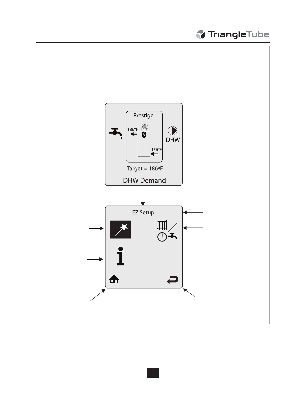
TriMax Operation
Press OK Button
The EZ Setup menu can
be accessed by selecting
this icon.
The CH / DHW Operation
Menu can be accessed by
selecting this icon.
Currently selected menu
The Boiler Information
Menu can be accessed
by selecting this icon.
The Home Screen icon at
the bottom of each screen
returns to the Home Screen
when selected.
The Previous Screen icon at the
bottom of each screen returns to
the previous screen when selected.
Main Menu
The Main Menu can be entered from the Home Screen by pressing the OK button. The menu
system utilizes icons to represent each selection. The currently selected menu is displayed
as a reversed image with a text description shown at the top of the display. Menus can be
entered by highlighting the desired icon and pressing the OK button.
45
Page 52
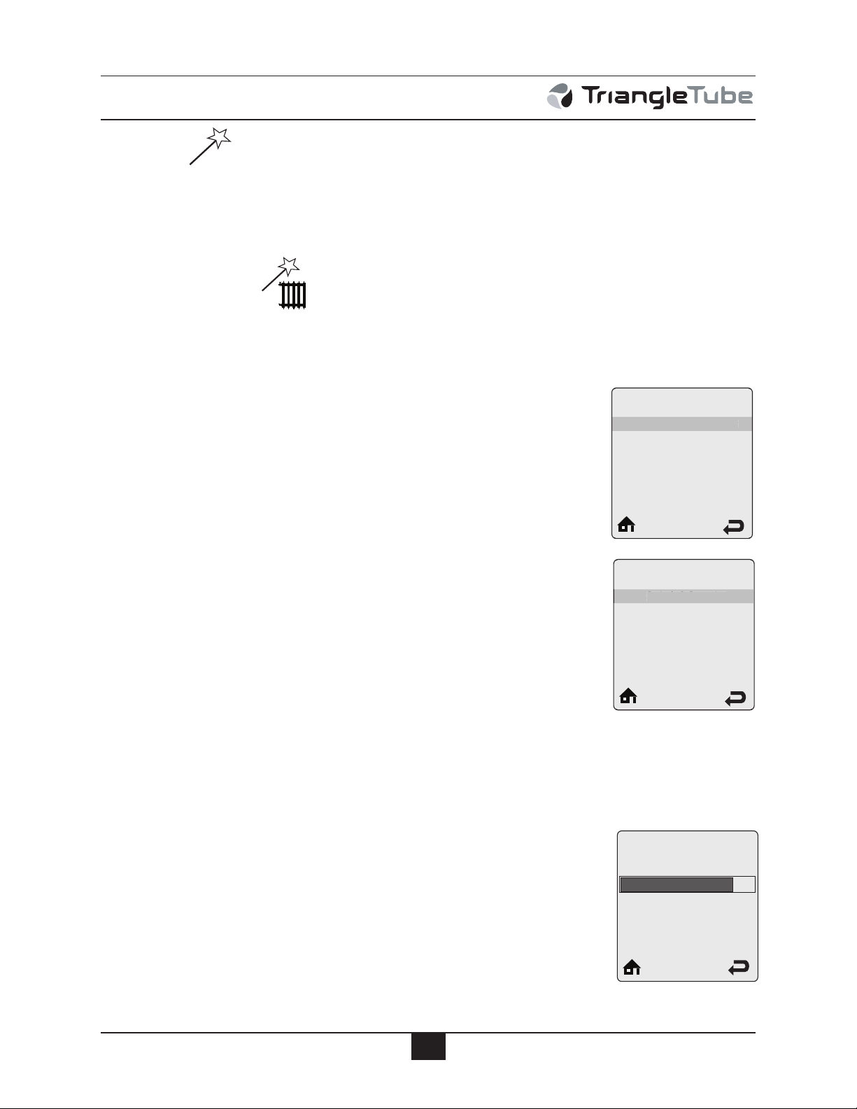
TriMax Operation
Select CH Demand
Switch & Outdoor Reset
Constant & Outdoor Reset
Constant & Setpoint
0-10V Modulation Signal
Switch & Outdoor Reset
Select CH Demand
Switch & Setpoint
Constant & Setpoint
0-10V Modulation Signal
OR
Switch & Setpoint
68ºF
194ºF
180ºF
CH1 Setpoint
EZ Setup
Navigation: Home Screen>Main Menu>EZ Setup
The EZ Setup menus provide a simple way to quickly customize the
TriMax for each installation. EZ Setup prompts the user to make selections
which allows the Prestige to be setup very quickly without searching
through long lists of settings and manually making adjustments.
Heating EZ Setup
Navigation: Home Screen>Main Menu>EZ Setup>Heating EZ Setup
Heating EZ Setup allows the installer to quickly customize the central heating settings for the application.
Select CH Demand Default: Switch & Outdoor Reset
Select CH Demand prompts the installer to select how a CH Demand is generated. Press the UP or DOWN buttons to select the CH Demand type then
press the OK button to store the setting. The Select CH Demand options are:
• Switch & Outdoor Reset – This option is only displayed when the
outdoor temperature sensor is connected. A central heating call from a
thermostat or zone panel will enable the Prestige and the setpoint will
vary with the outdoor temperature for central heating calls.
• Switch & Setpoint - This option is only displayed when the outdoor
temperature sensor is not connected. A central heating call from a thermostat or zone panel will enable the Prestige and the setpoint will be
fixed for central heating calls
• Constant & Outdoor Reset - This option is only displayed when the
outdoor temperature sensor is connected. The Prestige will maintain setpoint without an external call from a thermostat or zone panel. The setpoint will vary with the outdoor temperature for central heating calls.
• Constant & Setpoint - The Prestige will maintain setpoint without an
external call from a thermostat or zone panel. The setpoint will be fixed
for central heating calls.
• 0-10V Modulation Signal – This option allows the Prestige firing rate
to be controlled by an external control system.
CH1 Setpoint Default: 180°F [82°C]
CH1 Setpoint prompts the installer to enter the fixed setpoint for a CH1
heating call when a Setpoint option is chosen in Select CH Demand. Press
the LEFT or RIGHT buttons to adjust the CH1 Setpoint then press the
OK button to store the setting.
CH2 Setpoint Default: 140°F [60°C]
CH2 Setpoint prompts the installer to enter the fixed setpoint for a CH2
heating call when a Setpoint option is chosen in Select CH Demand. Press
the LEFT or RIGHT buttons to adjust the CH2 Setpoint then press the
OK button to store the setting.
46
Page 53
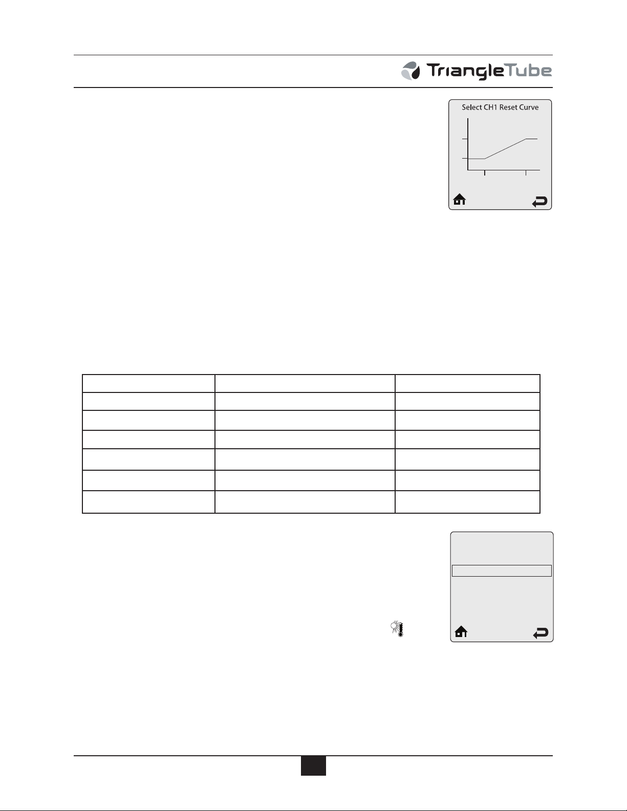
TriMax Operation
180ºF
120ºF
64ºF
0ºF
Current Settings
Off 78ºF
Off
Set Warm Weather
Shutdown Temperature
Select CH1 Reset Curve Default: Finned Tube Baseboard
Select CH1 Reset Curve prompts the installer to select an outdoor reset curve
for a CH1 heating call when an Outdoor Reset option is chosen in Select CH
Demand. Outdoor reset curve presets are available to cover most applications. The outdoor reset curve can also be adjusted to any desired settings in
the Installer Menu. Press the UP or DOWN buttons to select the outdoor
reset curve appropriate for the type of heating system then press the OK but-
ton to store the setting.
Select CH2 Reset Curve Default: Low Mass Radiant
Select CH2 Reset Curve prompts the installer to select an outdoor reset curve
for a CH2 heating call when an Outdoor Reset option is chosen in Select CH
Demand. Outdoor reset curve presets are available to cover most applications. The outdoor reset curve can also be adjusted to any desired settings in
the Installer Menu. Press the UP or DOWN buttons to select the outdoor
reset curve appropriate for the type of heating system then press the OK but-
ton to store the setting.
Table 3: Outdoor Reset Preset Selections
Preset Minimum Setpoint Maximum Setpoint
Low Mass Radiant 80ºF [27ºC] 140ºF [60ºC]
High Mass Radiant 80ºF [27ºC] 120ºF [49ºC]
Cast Iron Baseboard 100ºF [38ºC] 170ºF [77ºC]
Finned Tube Baseboard 120ºF [49ºC] 180ºF [82ºC]
Radiators 120ºF [49ºC] 170ºF [77ºC]
Fan Coil 140ºF [60ºC] 180ºF [82ºC]
Set Warm Weather Shutdown Temperature Default: OFF
Warm Weather Shutdown prompts the installer to enter an optional outdoor
temperature at which to disable the central heating function. The Prestige
will continue to respond to a domestic hot water call or a 0-10V
Modulation Signal when the outdoor temperature exceeds the Warm
Weather Shutdown Temperature setting. Press the LEFT or RIGHT buttons to adjust the Warm Weather Shutdown Temperature then press the OK
button to store the setting. The Warm Weather Shutdown icon is displayed on the home screen when the outdoor temperature reaches the
Warm Weather Shutdown Temperature.
47
Page 54
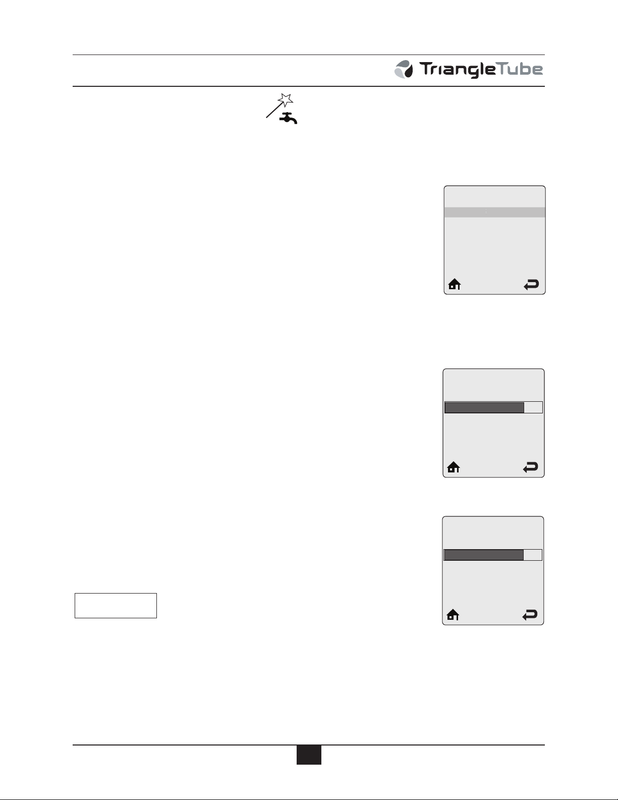
TriMax Operation
Select DHW Demand
Switch
Sensor
Switch
96ºF
194ºF
186ºF
Boiler
DHW Setpoint
68ºF
150ºF
140ºF
DHW
Storage Setpoint
Domestic Hot Water EZ Setup
Navigation: Home Screen>Main Menu>EZ Setup>DHW EZ Setup
Domestic Hot Water EZ Setup allows the installer to quickly customize the
domestic hot water settings for the application.
Select DHW Demand Default: Switch
Select DHW Demand prompts the installer to select the type of device which
will generate a DHW call. Press the UP or DOWN buttons to select the
DHW Demand type then press the OK button to store the setting. The Select
DHW Demand options are:
• Switch – A domestic hot water call from an aquastat or dry contact
switch will enable the Prestige with a fixed setpoint for a domestic hot
water call.
• Sensor – This option requires the use of Indirect Water Heater Sensor
PSRKIT22. The Prestige will monitor the DHW storage temperature
and generate a domestic hot water call when the temperature drops
below the DHW Storage Setpoint by 6ºF [3ºC].
Boiler DHW Setpoint Default: 186°F [86°C]
Boiler DHW Setpoint prompts the installer to enter the fixed boiler setpoint
temperature during a Domestic hot water call when the Switch option is chosen in Select DHW Demand. Press the LEFT or RIGHT buttons to adjust
the Boiler DHW Setpoint then press the OK button to store the setting.
DHW Storage Setpoint Default: 140°F [60°C]
DHW Storage Setpoint prompts the installer to enter the domestic hot water
storage setpoint temperature when the Sensor option is chosen in Select
DHW Demand. Press the LEFT or RIGHT buttons to adjust the DHW
Storage Setpoint then press the OK button to store the setting.
NOTICE
The Boiler DHW Setpoint will automatically be set 46°F [25°C]
higher than the DHW Storage Setpoint setting.
48
Page 55
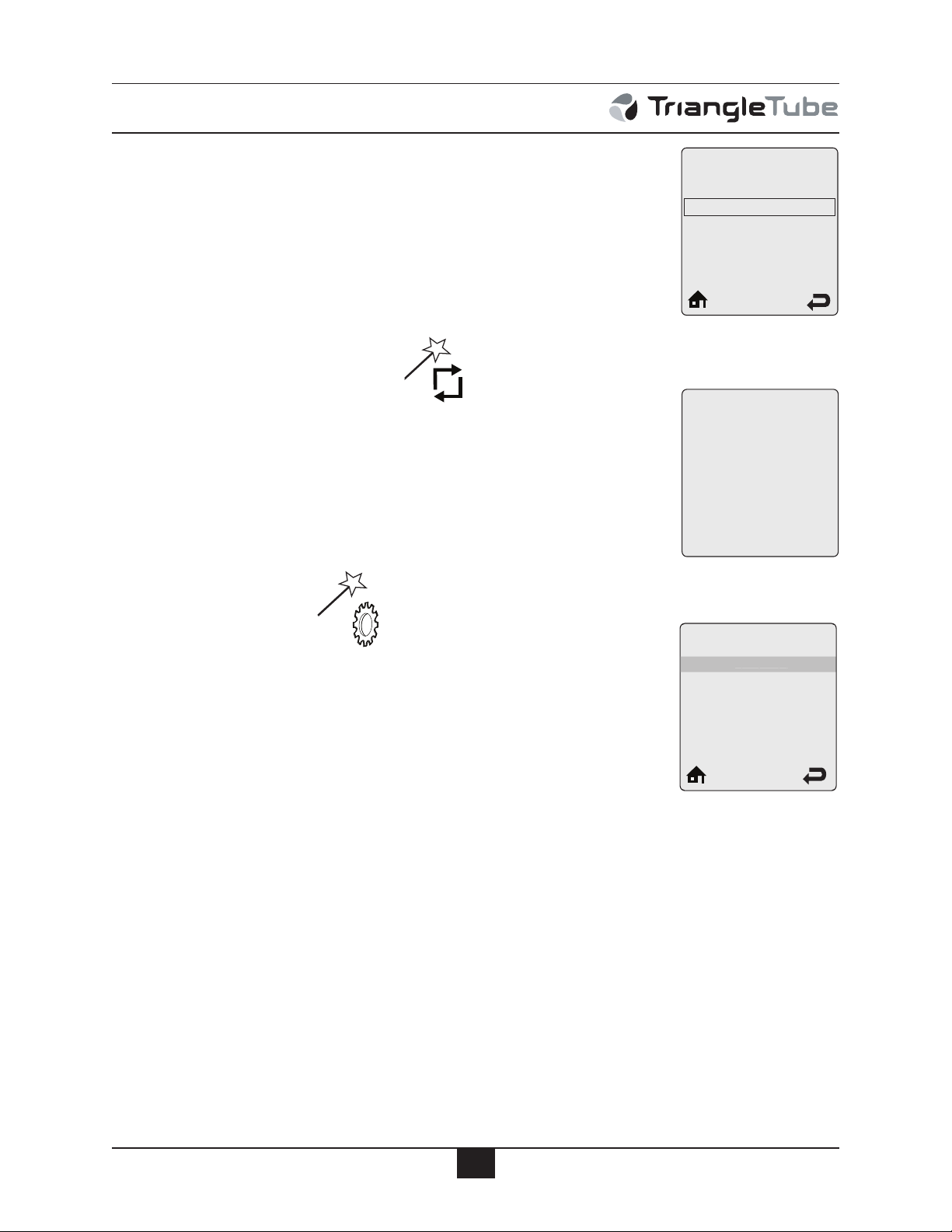
TriMax Operation
Off
60 min.
Off
DHW Priority Timeout
EZ Setup Reset
Press OK button
to restore factory settings.
Any other button
to keep current settings.
Select Units
Fahrenheit
Celsius
Fahrenheit
DHW Priority Timeout Default: Off
DHW Priority Timeout prompts the installer to enter an optional time limit
that a domestic hot water call has priority over a central heating call. Press
the LEFT or RIGHT buttons to adjust the DHW Priority Timeout then press
the OK button to store the setting.
EZ Setup Reset
Navigation: Home Screen>Main Menu>EZ Setup>EZ Setup Reset
EZ Setup Reset allows the installer to reset all EZ Setup settings back to
the original factory defaults. Follow the onscreen instructions to reset all
EZ Setup settings back to the original factory defaults.
Display EZ Setup
Navigation: Home Screen>Main Menu>EZ Setup>Display EZ Setup
Display EZ Setup allows the installer to select the type of temperature
units displayed as well as the language used for all text. Press the UP or
DOWN buttons to select then press the OK button to store the setting.
49
Page 56
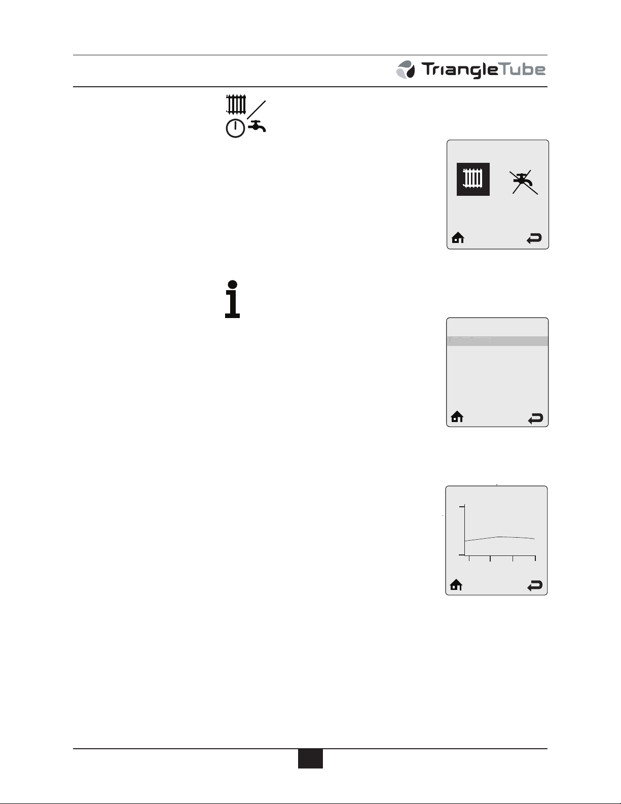
TriMax Operation
Heating Enabled
Boiler Information
Boiler Status
Heating Call
DHW Call
Boiler Firing Rate
Flame Ionization Current
Boiler Setpoint
Standby
No
No
0%
OuA
__
Boiler Status
Standby
194
68
-24.00
-16.00 -8.00
0.00
Boiler Setpoint
CH/DHW Operation
Navigation: Home Screen>Main Menu>CH / DHW Operation
CH / DHW Operation provides a simple way to disable either the central
heating or domestic hot water functions of the Prestige. Operation can be
enabled and disabled by selecting the central heating or domestic hot water
icon then pressing the OK button to toggle between enabled and disabled.
An icon with an X through it indicates that function has been disabled. The
disabled icon is also displayed on the home screen when a function has
been disabled.
Boiler Information
Navigation: Home Screen>Main Menu>Boiler Information>Boiler
Information
Boiler Information provides real time operating information of the
Prestige. Each line contains an information item followed by its current
value. Six information items are displayed on the screen at one time. Press
the UP or DOWN buttons to scroll through additional information items.
See page 51 for a list of all information items.
Boiler Information Logging
Some information items include a logging function which records one sample every 12 minutes to produce a graph of the last 24 hours. Select the information item in Boiler Information then press the OK button to view its
graph. The following items have a logging function:
• Boiler Firing Rate
• Flame Ionization Current
• Boiler Setpoint
• Boiler Supply Temperature
• Boiler Return Temperature
• Boiler Flue Temperature
• Outdoor Temperature
• DHW Storage Temperature
• External Modulation Signal
50
Page 57
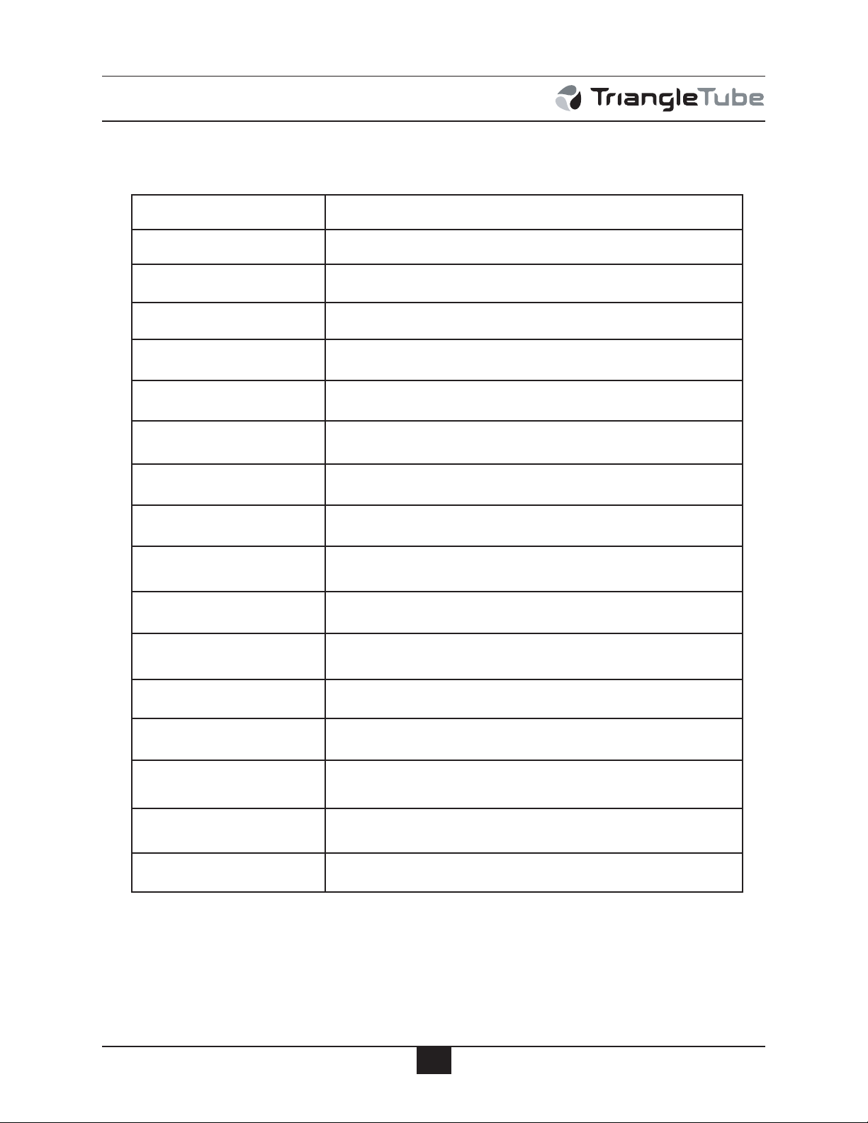
TriMax Operation
Information Item Description
Information Items
Boiler Status
Heating Call Displays if a central heating call is present.
DHW Call Displays if a domestic hot water call is present
Boiler Firing Rate Displays the current firing rate of the Prestige.
Flame Ionization Current Displays the current flame ionization current from the ignitor.
Boiler Setpoint Displays the current setpoint of the Prestige.
Boiler Supply Temperature Displays the current supply temperature of the Prestige.
Boiler Return Temperature Displays the current return temperature of the Prestige.
Boiler Flue Temperature Displays the current flue temperature of the Prestige.
Outdoor Temperature Displays the current outdoor temperature.
DHW Storage Temperature
Displays the current operating state of the Prestige. This is the same as
the status line on the home screen.
Displays the current DHW storage temperature when Indirect Water
Heater Sensor PSRKIT22 is installed.
External Modulation Signal
CH Ignitions
CH Runtime
DHW Ignitions
DHW Runtime
Displays the current external modulation signal being received from an
external controller.
Displays the number of central heating ignitions since the unit was
installed. This counter increases in increments of twenty.
Displays the number of hours the Prestige has run for a central heating
call since the unit was installed.
Displays the number of domestic hot water ignitions since the unit was
installed. This counter increases in increments of twenty.
Displays the number of hours the Prestige has run for a domestic hot water
call since the unit was installed.
51
Page 58
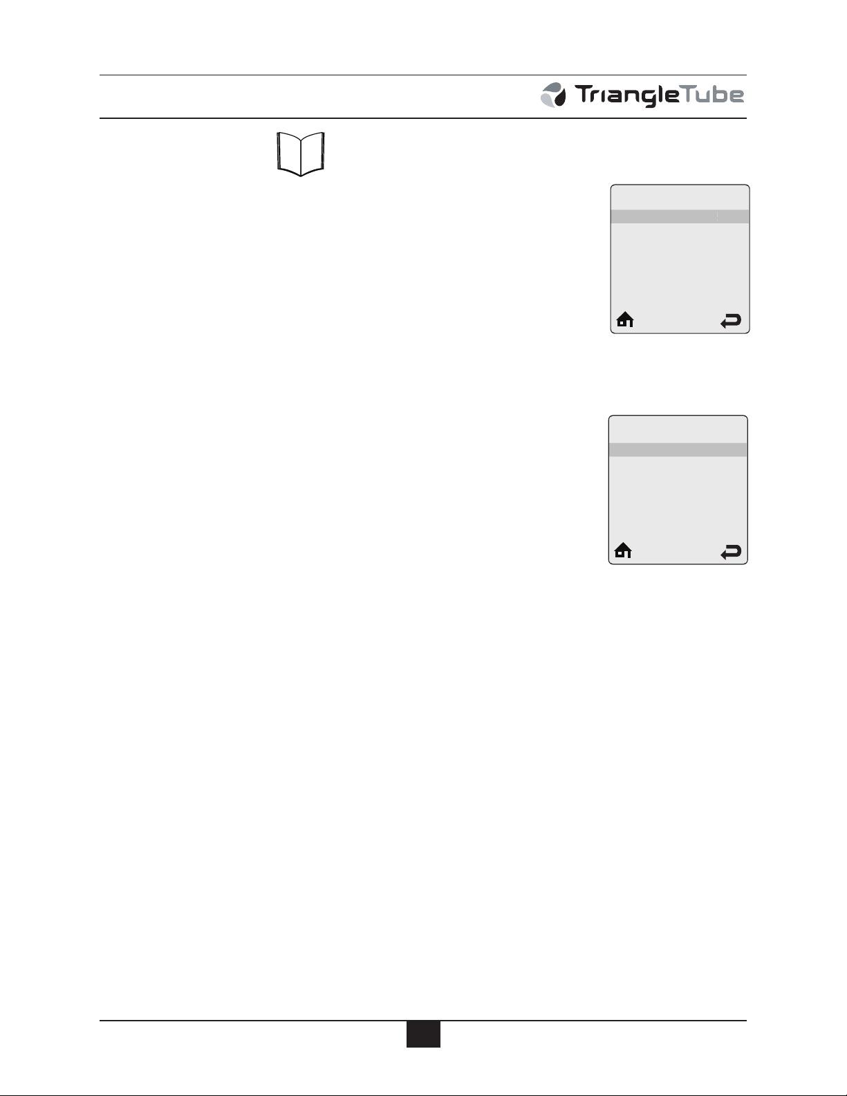
TriMax Operation
Lockout History
1: Low water
2: No error
3: No error
4: No error
5: No error
6: No error
5h ago
25h ago
25h ago
25h ago
25h ago
25h ago
Lockout Details
Low Water
Boiler Status
Heating Call
DHW Call
Boiler Firing Rate
Flame ionization Current
Standby
No
No
0%
OuA
a
b
c
d
e
f
b
b
b
b
a
b
c
d
e
f
b
b
a
b
c
d
e
a
b
c
d
e
f
b
b
b
b
a
b
c
d
e
f
b
b
a
b
c
d
a
b
c
d
e
f
b
b
b
b
a
b
c
d
e
f
b
b
a
b
c
d
e
a
b
c
d
e
f
b
b
b
b
a
b
c
d
e
f
b
b
f
b
g
a
b
c
d
Lockout History
Navigation: Home Screen>Main Menu>Boiler Information>Lockout
History
Lockout History records the last eight lockouts. Each line contains a lockout description followed by how long ago the lockout occurred. Six lockouts are displayed on the screen at one time. Press the UP or DOWN buttons to scroll through additional lockouts. See pages 54 & 55 for a list of
lockouts and descriptions.
Lockout Details
Some information items are recorded at the time of a lockout to aid in diagnosing the cause of the lockout. Select the lockout description in Lockout
History then press the OK button to view the recorded information. Press the
UP or DOWN buttons to scroll through the recorded information. The following information items are recorded at the time of a lockout:
• Boiler Status
• Heating Call
• Domestic Call
• Boiler Firing Rate
• Flame Ionization Current
• Boiler Setpoint
• Boiler Supply Temperature
• Boiler Return Temperature
• Boiler Flue Temperature
• Outdoor Temperature
• System Temperature
52
Page 59
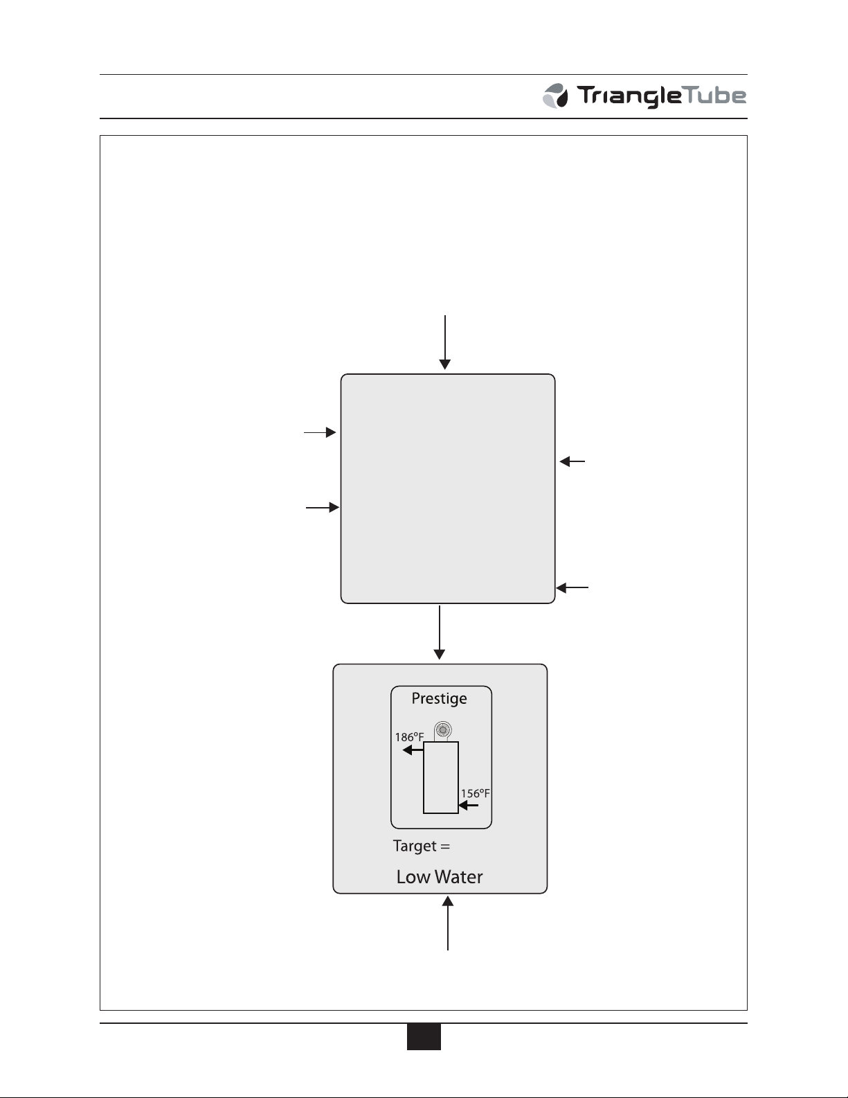
TriMax Operation
Press any ARROW Button
The status line now displays the lockout
The lockout message is displayed at the top of the screen
The lower right corner
displays the lockout
reference code.
The second sentence
gives a possible cure
for the lockout.
The first sentence gives
a description of the
lockout.
The third sentence tells
how to reset the lockout.
Press any ARROW button
to return to the Home Screen while
locked out.The main menu can then
be entered from the Home Screen to
help diagnose the problem. Select
the Home Screen icon at the bottom
of any menu screen to return to the
Lockout Screen.
Water level has fallen below
an acceptable operating
level. Increase pressure to
normal range. Boiler will
automatically reset once
water level returns to normal
Low Water
If problem persists,
call for service
E37
--
Lockout Screen
The Lockout Screen replaces the Home Screen if a lockout occurs. The screen backlight will
also illuminate constantly while the Prestige is locked out. Pressing any arrow button will
return to the Home Screen so that additional troubleshooting can be performed. See pages 54
and 55 for a list of lockouts and descriptions.
53
Page 60
TriMax Operation
Manual Reset Hard Lockouts
Code Lockout Message Description
E1 Failed Ignition The burner failed to light after 5 ignition attempts.
E2 False Flame A flame is being detected prior to ignition.
E3 High Boiler Temperature Boiler temperature exceeds 212°F [100ºF]
E5 Blower Speed
E8 Flame Circuit Error Flame circuit test failed.
E9 Gas Valve Circuit Error Gas valve circuit test failed.
E13 Reset Limit Reached Resets are limited to 5 every 15 minutes.
E15 Sensor Drift Supply or return sensor reading has drifted.
E16 Supply Sensor Stuck Supply sensor reading is not changing.
E17 Return Sensor Stuck Return sensor reading is not changing.
E18 Sensor Failure Supply or return sensor reading changed very rapidly.
E21 Internal Control Fault A / D conversion error.
E30 Supply Sensor Shorted
Blower is not at correct speed or speed signal is not being received
by control module.
A short circuit has been detected in the boiler supply temperature
sensor circuit.
E31 Supply Sensor Open
E43 Return Sensor Shorted
E44 Return Sensor Open
E80 Return > Supply Return temperature is higher than supply temperature.
E87 External Limit Open An external manual reset limit has opened
An open circuit has been detected in the boiler supply temperature
sensor circuit.
A short circuit has been detected in the boiler return temperature
sensor circuit.
An open circuit has been detected in the boiler return temperature
sensor circuit.
54
Page 61
TriMax Operation
Automatic Reset Soft Lockouts
Code Lockout Message Description
E7 High Flue Temperature Flue temperature exceeds high limit.
E12 Internal Control Fault EEPROM misconfiguration
E25 Internal Control Fault CRC check error.
E32 DHW Sensor Shorted A short circuit has been detected in the DHW temperature sensor circuit.
E33 DHW Sensor Open An open circuit has been detected in the DHW temperature sensor circuit.
E34 Low Voltage Line voltage has fallen below an acceptable operating level.
E37 Low Water Water level has fallen below an acceptable operating level.
E45 Flue Sensor Shorted
E46 Flue Sensor Open
E76 External Limit Open An external automatic reset boiler limit has opened.
E81 Sensor Drift Supply and return temperatures are not equal.
E89 Incorrect Setting A parameter setting is outside the settings range.
E90 Firmware Mismatch Control module and display firmware versions are incompatible.
E91 System Sensor Shorted A short circuit has been detected in the system temperature sensor circuit.
E92 System Sensor Open An open circuit has been detected in the system temperature sensor circuit.
E93 Outdoor Sensor Shorted A short circuit has been detected in the outdoor temperature sensor circuit.
E94 Internal Display Fault Display memory error.
E95 Supply Sensor Error Supply sensor reading is invalid.
E96 Outdoor Sensor Open
A short circuit has been detected in the boiler flue temperature sensor
circuit.
An open circuit has been detected in the boiler flue temperature sensor
circuit.
An open circuit has been detected in the outdoor temperature sensor
circuit.
E97 Cascade Mismatch Cascade configuration has changed.
E98 Cascade Bus Error Communication with other boilers has been lost.
E99 Controller Bus Error
Communication between boiler display and control module has been
lost.
55
Page 62
Start-Up Preparation
SECTION X - Start-Up Preparation
NOTICE
Requirements below must be met for
warranty coverage of Prestige heat
exchangers. A thorough cleaning of any
existing system, using approved heating
system cleaning agents is required prior
to installation of the Prestige boiler.
System should be treated with an
approved inhibitor after filling for long
term protection.
Check Boiler System Water Chemistry
WARNING
Do not use petroleum-based cleaning or
sealing compounds in the boiler system.
Damage to seals and gaskets in the system components could occur, resulting in
substantial property damage.
Chlorinated Water
Do not use the PRESTIGE Solo to heat a
swimming pool or spa directly.
Maintain the chlorine level of the water at levels considered safe for drinking.
Flush Boiler to Remove Sediment
The installer must flush the boiler system to
remove any sediment to allow proper operation
of the PRESTIGE Solo .
Flush the systems until the water runs clean
and is free of sediment.
For zoned systems, each zone should be
flushed through a purge valve. Purge valves
and isolation valves should be installed on each
zone to allow proper flushing of the system.
Cleaning of Old Boiler/System:
• Drain the existing system.
NOTICE
System water including additives must be
practically non-toxic, having a toxicity
rating or Class of 1, as listed in Clinical
Toxicology of Commercial Products.
Water pH Level 6.0 to 8.0
Maintain the boiler water pH between 6.0 and
8.0. Check using litmus paper or contact a water
treatment company for a chemical analysis.
If the pH does not meet this requirement, do
not operate the PRESTIGE Solo or leave the
unit filled until the condition is corrected.
Water Hardness Less Than 7 Grains
For areas with unusually hard water (hardness
above 7 grains) consult a water treatment
company.
• Fill system with fresh water and cleaner,
place existing boiler in operation and run
all zones.
• Follow manufacturer’s instructions for
proper cleaner concentration and proper
cleaning time.
• Thoroughly drain and flush system with
fresh water after cleaning.
• Install new boiler, fill system with fresh
water and proper amount of inhibitor.
• Verify pH and inhibitor level per inhibitor
manufacturer’s specs; add inhibitor if
necessary.
Cleaning of New Boiler/System:
• Install new boiler and flush system with
cleaner water to remove any debris.
• Fill system with fresh water and proper
amount of inhibitor.
• Verify pH and inhibitor level per inhibitor
manufacturer’s specs; add inhibitor if
necessary.
56
Page 63
Start-Up Preparation
Check and Test Antifreeze
For boiler systems containing antifreeze solutions, follow the antifreeze manufacturer’s
instructions in verifying the inhibitor level and
to ensure the fluid characteristics are within
specification requirements.
Due to the degradation of inhibitors over time,
antifreeze fluids must be periodically replaced.
Refer to the manufacturer of the antifreeze for
additional instructions.
Use of Antifreeze in the Boiler System
WARNING
NEVER use automotive or ethylene glycol
antifreeze or undiluted antifreeze in the
primary system as freeze protection. This
can cause severe personal injury, death or
substantial property damage if ignored.
Determine the antifreeze fluid quantity using
the system water content volume and following
the antifreeze manufacturer instructions.
The water volume of the PRESTIGE Solo is
approximately 3 gallons [12 L] for PRESTIGE
Solo 60 or 5 gallons [19 L] for PRESTIGE Solo
175/250 or 7 gallons [26 L] for PRESTIGE Solo
399 . Remember to include the volume of the
expansion tank.
NOTICE
System water, including additives, must
be practically non-toxic, having a toxicity
rating or Class of 1, as listed in Clinical
Toxicology of Commercial Products.
Filling the Boiler System
1. Close the boiler drain valve located on the
bottom of the unit and any manual or automatic air vent in the system.
2. Open all system isolation valves.
3. Fill the boiler system to correct system
pressure. Correct pressure will vary with
each application.
NOTICE
Typical residential system fill pressure is
12 psi. System pressure will increase
when system temperature increases.
Operating pressure of the system should
never exceed 25 psi.
4. Purge air and sediment in each zone of the
boiler system through the purge valve.
Open air vents to allow air to be purged in
the zones.
5. Once the system is completely filled and
purged of all air and sediment, check the
system pressure and check/repair any leaks.
Check with local codes requirements for the
installation of backflow preventers or actual
disconnection from the boiler’s cold water fill
or make up water supply line.
NOTICE
Massachusetts Code requires the installation of a backflow preventer if
antifreeze is used.
Ensure the concentration of antifreeze to water
does not exceed a 50/50 ratio.
WARNING
Unrepaired system leaks will cause continual makeup water to be added to the
boiler. Continual makeup water will
cause mineral buildup within the heat
exchanger, reducing the heat transfer,
causing possible heat buildup and eventual heat exchanger failure.
Check Low Water Cut-Off Device
- The PRESTIGE Solo is provided with a
factory installed LWCO device that measures system pressure of more than 10 psi.
57
Page 64
Start-Up Preparation
- Remove the front jacket panel and check for
continuity across the low water cut-off device
wire terminals. The contacts should be closed
when system pressure is greater than 10 psi.
See item 6, on Fig. 36 page 78(PRESTIGE
Solo 60) or on Fig. 37 page 79 (PRESTIGE
Solo 175/250) or Fig. 38 page 80 (PRESTIGE
Solo 399) for location of the LWCO.
Check For Gas Leaks
WARNING
Prior to start-up and during initial operation, smell near the floor and around the
unit for gas odorant or any unusual odor.
Do not proceed with the start-up if there
is any indication of a gas leak. Any leaks
found must be repaired immediately.
WARNING
Propane installations only - The propane
supplier mixes an odorant with the
propane to make its presence detectable.
In some cases the odorant can fade and
the gas may no longer have an odor.
Prior to start-up of the unit and periodically after start-up have the propane supplier check and verify the odorant level.
Check Thermostat Circuit
- Disconnect the external thermostat wires
from the low voltage terminal strip.
NOTICE
In systems using 3-wire zone valves, backfeed of voltage to the unit is a common
problem. Use an isolation relay to prevent
voltage from the external circuit entering
the PRESTIGE Solo control panel.
- Reconnect the external thermostat
wires to the low voltage terminal strip.
Inspection of Condensate Drain Assembly
1. Inspect and ensure the Condensate Drain
Assembly is properly installed as described
on page 24 and shown in Fig. 14 on page 25.
2. Remove the plug from the Condensate
Drain Assembly and fill with fresh water.
NOTICE
The condensate drain assembly must be
filled with water when the PRESTIGE
Solo is in operation. The condensate
drain assembly prevents flue gas emissions from entering the condensate line.
Failure to ensure trap is filled with water
could result in severe personal injury or
death.
3. Re-Install plug in condensate drain assembly.
- Connect a voltmeter across the wire ends of
the external thermostat wiring.
- Close each thermostat, zone valve and
relay in the external circuit one zone at a
time and check the voltage reading across
the wire ends.
- There should NEVER be voltage measured
at the wire ends.
- If voltage is measured at the panel under any
condition, check and correct the external wiring.
58
Page 65

Start-Up Procedures
SECTION XI - Start-Up Procedures
Final Checks Before Start-Up
c Read page 40 through 55 regarding the
operation of the TriMax Boiler Managemnt
System.
c Verify the PRESTIGE Solo and the boiler
system are full of water and all system
components are correctly set for operation,
including the minimum flow rate through
the boiler, see pages 91 through 93.
c Verify Start-up Preparation items outlined on
pages 56 thru 58 have been completed.
c Verify all electrical connections are correct
and securely fastened.
c Inspect vent and combustion air piping for
signs of deterioration from corrosion, physical
damage or sagging. Verify combustion air
and vent piping are intact and correctly
installed and supported. Reference the PRESTIGE Solo vent supplement.
c Verify burner configuration - Propane only.
- Check for proper labeling on the gas
valve and the rating label for propane
configuration.
- If there is doubt on the burner configuration, remove the gas valve and check for
proper propane gas orifice size: 0.120”
(3.1 mm) for PRESTIGE Solo 60, 0.221”
(5.6 mm) for PRESTIGE Solo 175, 0.250”
(6.3 mm) for PRESTIGE Solo 250, 0.264”
(6.7 mm) for PRESTIGE Solo 399. Refer
to Figs. 16 & 17, page 29 for location of
the propane gas orifice.
PRESTIGE Solo Start-Up
1. Press the ON-OFF button located on the
front control panel to the OFF position. Turn
ON the electrical supply/service to the unit.
2. Read and follow the Operating Instructions
outlined on page 62.
If PRESTIGE Solo Does Not Start Correctly
1. Check for loose electrical connections,
blown fuses, (on control module and in terminals) or an open service switch.
2. Verify CH and DHW operation is enabled.
A radiator or faucet icon with an X through
it indicates that function is disabled.
3. Check continuity across the LWCO device
for a closed circuit. See item 6 on Fig. 36,
page 78 and item 6 Fig. 37, page 79 and
Fig. 38, page 80.
4. Is an external limit control (if applicable)
open? Ensure the external limit is reset to
the closed position.
5. Are the gas supply valves open at the unit
and meter?
6. Is incoming gas supply pressure at the unit
more than 5”w.c. and less than 13” w.c. for
natural or propane with all gas appliances
ON or OFF.
7. Are the heating thermostats set above room
temperature?
If none of these conditions correct the problem,
refer to the PRESTIGE Solo Trouble-Shooting
Guide or contact Triangle Tube Tech Service.
NOTICE
For natural gas applications the Prestige
60 requires an orifice: 0.204” (52mm), and
the Prestige 399 requires an orifice: 0.330”
(8.6 mm)
c Ensure the vent Condensate Drain
Assembly is filled with water.
Check the PRESTIGE Solo and System
c Check Boiler Piping.
Check Boiler system piping and components for leaks. If found, shut down
the unit and repair immediately.
Purge any remaining air from the system
piping. Air in the system piping will
interfere with circulation creating heat
distribution problems and system noise.
59
Page 66
Start-Up Procedures
Manual Operation
Released
O
O
O
CH
CH1
FAN
DHW
SYS
CH2
c Check Vent Piping and Combustion Air
Piping.
Check for gas-tight seal at every connection and seam of the venting and
combustion air piping.
WARNING
Venting system must be sealed gas-tight
to prevent flue gas spillage and potential
carbon monoxide emissions, which will
result in severe personal injury or death.
c Check Gas Piping
Check around the unit for gas odor following the procedure outlined in this
manual on Page 58.
WARNING
If any gas leaks are found or suspected,
shut the unit down immediately. Use a
gas detection device or bubble test to
locate the source of the gas leak and
repair at once. Do not operate the unit
until the leak is corrected. Failure to
comply with this procedure could result
in severe personal injury, death or substantial property damage.
2. Test for CO2 or O2 and for CO during
high firing rate. The combustion readings should be within the range listed in
Table 4. The CO level should not
exceed 100 ppm when combustion is
correct. Perform the following proce-
dure to manually place the burner into
high fire.
a. Press the round INSTALLER button.
Reference Fig. 31, page 41.
b. Enter the installer access code “054” by
using the LEFT and RIGHT buttons to
select a digit and the UP and DOWN
buttons to change the digit. Press the
OK button to enter the access code.
c. Press the RIGHT button to highlight
the Manual Operation icon then
press the OK button.
d. Press the OK button while the FAN
icon is highlighted to manually fire the
burner and power the CH circulator.
c Verify Flame Pattern and Combustion
1. Check the flame pattern through the
inspection port of the heat exchanger.
The flame should be blue and stable.
The flame should be the length of the
burner head openings.
WARNING
The combustion testing and adjustments
must be performed by a qualified
installer, service agency or the gas supplier. All combustion measurements must be
performed with calibrated equipment to
ensure proper reading and accuracy.
NOTICE
An adequate CH load must be present to
dissipate the heat generated during the
combustion test. If an adequate CH load
is not available, an indirect water heater
can be used to dissipate the heat by creating a DHW call which will enable the
DHW circulator.
60
Page 67
Start-Up Procedures
e. Press the LEFT and RIGHT buttons to
adjust the firing rate from 0% to 100%.
Hold down the LEFT or RIGHT button to rapidly increase or decrease the
firing rate.
Table 4: Recommended Combustion Levels
Natural Gas
All Models
O2 Min. 2.30% 2.70% 3.70%
O2 Max. 5.30% 4.70% 5.20%
CO2 Min. 8.80% 10.70% 10.00%
CO2 Max. 10.50% 12.00% 11.00%
CO Max. 100 ppm 100 ppm 100 ppm
Propane
Solo 60/175/250
Propane
Solo 399
f. Press the OK button while the FAN
icon is highlighted to shutdown the
burner.
c Measure Input - Natural Gas Only
1. Ensure the boiler is firing at maximum firing
rate. To manually place the boiler into high
fire mode, reference page 60.
2. Operate the unit for approximately 10
minutes.
3. Turn off all gas appliances within the building, except the PRESTIGE Solo.
4. At the gas meter, record the time required
to use one cubic foot of gas.
5. Calculate Natural gas input using the following equation:
3600 x 1000 / number of second recorded
for one cubic foot of gas = BTU/H.
6. The BTU/H calculated should approximate
the input rating listed on the unit.
g. Cycle power to the Prestige once com-
bustion testing is complete to return to
normal operation.
WARNING
The combustion levels should be measured at high firing rate. If the combustion levels are not within the range given
in Table 4 for the firing rate, shut the
boiler down and contact Triangle Tube
Engineering Department. Failure to
comply with this requirement could
result in severe personal injury, death or
substantial property damage.
61
Page 68
Start-Up Procedures
FOR YOUR SAFETY READ BEFORE LIGHTING
WARNING
If you do not follow these instructions exactly, a fire or explosion may
result causing property damage, personal injury or loss of life.
A. This appliance does not have a pilot. It is
equipped with an ignition device which automatically lights the burner. DO NOT try to light the
burner by hand.
B. BEFORE OPERATING, smell all around the
appliance area for gas. Be sure to smell next to
the floor because some gas is heavier than air and
will settle on the floor.
WHAT TO DO IF YOU SMELL GAS
• Do not try to light any appliance.
• Do not touch any electric switch; do not use
any phone in your building
•Immediately call your gas supplier from a
neighbor’s phone. Follow the gas supplier’s
instructions.
OPERATING INSTRUCTIONS
1. STOP! Read the safety information above. This
appliance is equipped with an ignition device
which automatically lights the burner. DO NOT
try to light the burner by hand.
2. Set room thermostat(s) to lowest setting. Turn the
external manual gas valve handle clockwise
“CLOSE” (valve handle shall be per-
pendicular to gas piping).
3. Turn the service switch on the PRESTIGE control panel OFF.
4. Remove the front jacket panel on the unit.
5. Turn the external manual gas valve handle
counter clockwise to “OPEN” gas supply (valve handle shall be parallel to gas piping).
6. Wait five (5) minutes to clear out any gas. If you
then smell gas in the jacket enclosure or around
the unit, STOP! Follow “B” in the safety information above. If you don’t smell gas, go to the
next step.
• If you cannot reach your gas supplier, call the
fire department.
C. Use only your hand to turn the external manual gas
valve. Never use tools. If the valve will not turn by
hand, don’t try to repair it; call a qualified service
technician. Force or attempted repair may result in
a fire or explosion.
D. Do not use this appliance if any part has been
under water. Immediately call a qualified service
technician to inspect the appliance and to replace
any part of the control system and any gas control
which has been under water.
7. Turn the service switch on the PRESTIGE control panel “ON”.
8. Set room thermostat(s) to desired setting(s).
9. The PRESTIGE control panel display will show
the current operating status on the Status Line at
the bottom of the screen. “Standby” means there is
no call for heat (all thermostats are satisfied). “CH
Demand” indicates a space heating call has been
received. “DHW Demand” indicates a domestic
hot water call has been received. A flame icon will
be displayed when the unit is fired.
10. If the unit will not operate with a call for heat and the
system piping is not hot, follow the instructions “To
Turn Off Gas to Appliance”, below and call your
service technician or gas supplier.
11. Replace the front jacket panel. Make sure the panel is
seated firmly in place and all mounting screws are
tightened.
TO TURN OFF GAS TO APPLIANCE
1. Set the room thermostat to lowest setting.
2. Turn the service switch on the PRESTIGE control panel to “OFF”
3. Turn the external manual gas valve handle clockwise to “CLOSE”.
62
Page 69
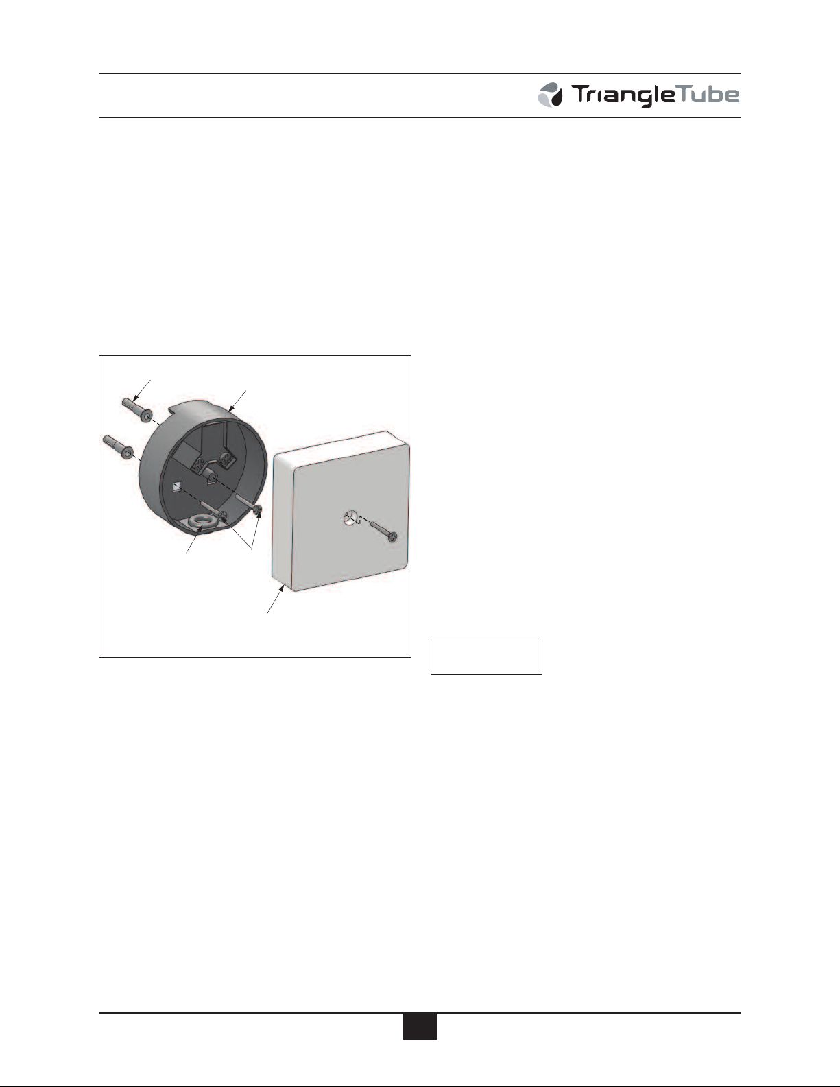
Outdoor Reset Control
Sensor Enclosure
(2) Plastic Anchors
Seal Gasket
Front Cover
(2) Mounting
Screws
SECTION XII - Outdoor Reset
Control
The boiler setpoint for a space heating call can
be fixed or vary with the outdoor temperature.
The use of the outdoor reset function is recommended to optimize boiler efficiency. The
default setting of the boiler is for outdoor reset
operation. The outdoor reset function must be
disabled in Heating EZ Setup after the outdoor
sensor is disconnected from the boiler. (See
NOTICE on page 64).
4. Mount the sensor enclosure at an elevation
on the exterior wall to prevent accidental
damage or tampering.
5. Avoid mounting the enclosure in areas subjected to excessive moisture.
6. Once an area on the exterior wall has been
determined, to affix the enclosure use the
enclosure as a template to mark the location
of the mounting screws.
7. Using a 3/16” drill bit, drill 2 pilot holes on
the marked locations.
8. Tap the enclosed plastic anchors into the
pilot holes. Use care not to damage the
anchors.
9. Mount the sensor enclosure using the
screws provided.
Wiring the Sensor
1. Cut a small slit in the seal gasket and route
18 AWG 2-wire cable or similar wire cable
through the seal gasket into the enclosure.
Fig. 32: Sensor Enclosure and Components
Mounting the Outdoor Sensor
1. Remove the front cover and mounting
screws / anchors from the sensor enclosure.
2. When mounting the enclosure, the exterior
wall selected should represent the heat load
of the building. Typically a northern or
northeastern wall will suit most buildings.
A southern facing wall for those buildings,
which may have large glass walls or windows on the southern face.
3. Ensure the sensor enclosure is shielded
from direct sunlight or the effects of heat or
cold from other sources (exhaust fans,
appliance vents...) to prevent false temperature sensing.
2. Route the sensor wire back to the PRESTIGE Solo boiler, ensuring the wires are
not run parallel to telephone or power
cables.
NOTICE
If the sensor wires are located in an area
with sources of potential electromagnetic
interference (EMI) the sensor wires
should be shielded or the wires should be
routed in a grounded metal conduit. If
using shielded cable, the shielding
should be connected to the common
ground of the unit.
5. Connect the sensor wires to the outdoor sensor terminals on the low voltage terminal
strip located inside the boiler enclosure (see
boiler wiring diagram, Fig. 19 page 31).
63
Page 70
External Modulating Control
SECTION XIII - External Modulating
The boiler can directly accept an analog 0-10
VDC signal to control the firing rate from an
external modulating boiler controller such as
the Optima SCC4.
Wiring the Modulating Controller
Run two 18 gauge wires from the external
modulating boiler controller’s 0-10 VDC boiler output to the modulation signal terminals on
the low voltage terminal strip inside the boiler.
(see boiler wiring diagram, Fig. 19 page 31).
This signal will both enable and modulate the
boiler. No wiring is required at the thermostat
terminals.
NOTICE
Ensure that the polarity of the connections from the external modulating boiler controller to the boiler are correct.
Reversed polarity will lead to no
response from the boiler.
TriMax Adjustment
The TriMax control must be programmed to
accept the 0-10 VDC signal from the external
modulating boiler control.
1. Use the Heating EZ Setup function to set
the CH Demand to 0-10V Modulation
Signal. Reference page 46 for the Heating
EZ Setup function.
Programming of External Modulating
Control
The external modulating control must be programmed to send 2 VDC to enable the boiler
and run it at low fire, and 10 VDC to run the
boiler at high fire. Once the control enables the
boiler, it must wait 30 seconds to allow the burner to stabilize before modulating the boiler.
IMPORTANT
In accordance with Section 325 (f) (3) of the Energy Policy and Conservation Act, this boiler is equipped with a feature that saves energy by reducing the boiler water temperature as the
heating load decreases. This feature is equipped with an override which is provided primarily to permit the use of an external energy management system that serves the same function.
THIS OVERRIDE MUST NOT BE USED UNLESS AT LEAST ONE OF THE FOLLOWING CONDITIONS IS TRUE.
• An external energy management system is installed that reduces the boiler water temperature as the heating load decreases.
• This boiler is not used for any space heating
• This boiler is part of a modular or multiple boiler system having a total input of
300,000 BTU/hr or greater.
• This boiler is equipped with a tankless coil.
64
Page 71
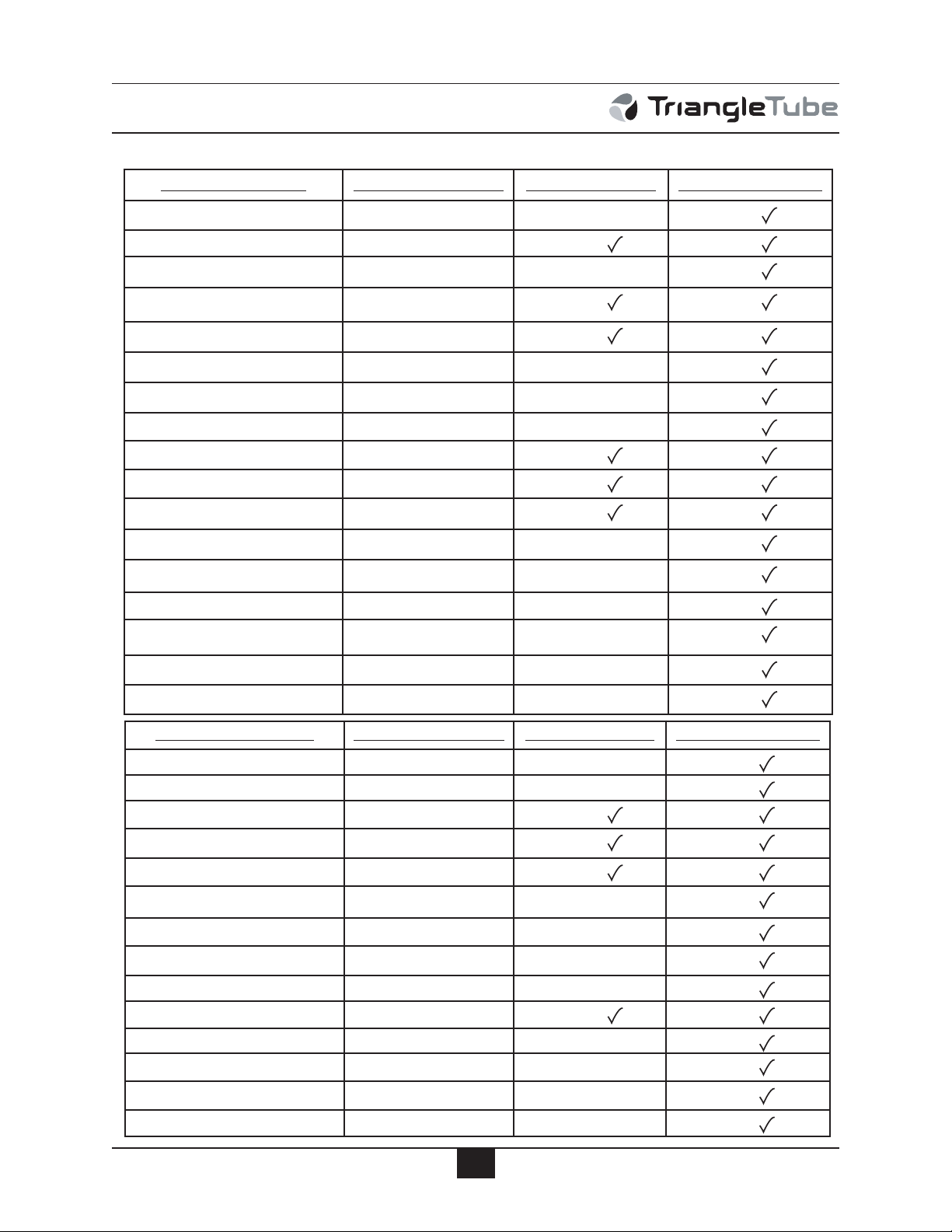
External Modulating Control
Factory TriMax Setting
HEATING SETTING FACTORY DEFAULT EZ SETUP RESET INSTALLER RESET
Heating Operation Enabled
Demand Switch & Outdoor Reset
Absolute Max CH Setpoint 194°F [90°C]
CH1 Maximum Setpoint 180°F [82°C]
CH1 Minimum Setpoint 120°F [49°C]
Reset Curve Coldest Day 0°F [-18°C]
Reset Curve Warmest Day 64°F [18°C]
CH2 Circuit Enabled
CH2 Maximum Setpoint 140°F 60°C]
CH2 Minimum Setpoint 80°F [27°C]
Warm Weather Shutdown OFF
Pump Constant Circulation Disabled
CH Post Pump Time 1 minute
Freeze Protection Enabled
Frost Protection Setpoint -22°F [-30°C]
Parallel Shift Value 0°F [0°C]
CH Call Blocking 1 minute
DOMESTIC SETTING FACTORY DEFAULT EZ SETUP RESET INSTALLER RESET
DHW Operation Enabled
Prestige Model Solo
Demand Switch
Boiler DHW Setpoint 186°F [86°C]
DHW Storage Setpoint 140°F [60°C]
DHW On Differential 6°F [3°C]
DHW Storage Adder 46°F [25°C]
System Pump During DHW Disabled
DHW Post Pump Time 1 minute
DHW Priority Timeout OFF
DHW Priority Enabled
DHW Call Blocking 0 minute
DHW to CH Call Blocking 1 minute
Antilegionella Function Disabled
65
Page 72

Check-Out Procedures
SECTION XIV- Check-Out Procedures
NOTICE
Perform the following check-out procedures as outlined and check off items as
completed. When procedures are completed, the installer should complete the
installation record on page 67.
Check-Out Procedures
c Boiler system water chemistry checked and
verified as outlined on page 56.
c Boiler system was completely flushed to
remove any debris/sediment.
c The boiler air vent and any automatic air
vents placed within the system are open
one full turn.
c Air is purged from the heating zones and
boiler system piping.
c In multiple zone applications, adjusted for
correct flow of boiler water to each zone.
c Checked and verified room thermostat(s)
function properly and the thermostat(s)
heat anticipator (if used) was properly set.
c Observed several operating cycles for
proper operation of the PRESTIGE Solo
and the system.
c Set the room thermostat(s) to the desired
room temperature.
c Reviewed all instructions shipped with the
PRESTIGE Solo with the homeowner or
maintenance personnel.
c Completed the Installation Record on page
67.
c Ensure all manuals and other documents
are returned to the Installation envelope
and given to the owner for safekeeping.
c If applicable, confirm that the burner has
been properly configured for Propane as
outlined on page 28.
c Thermostat circuit wiring checked and ver-
ified that no voltage is present to the low
voltage terminals as outlined on page 58.
c Operating Instructions on page 62 were fol-
lowed during start-up.
c Combustion levels and flame pattern veri-
fied as outlined on page 60.
c Measured the rate of input on Natural Gas
as outlined on page 61.
c Checked the incoming gas pressure to the
PRESTIGE Solo to ensure a minimum
pressure of 5”w.c during flow conditions to
all gas appliances and a maximum pressure
of 13”w.c during non-flow conditions for
Natural and Propane.
c Adjusted balancing valves and system limit
controls to provide design temperatures to
the primary space heating system.
66
Page 73
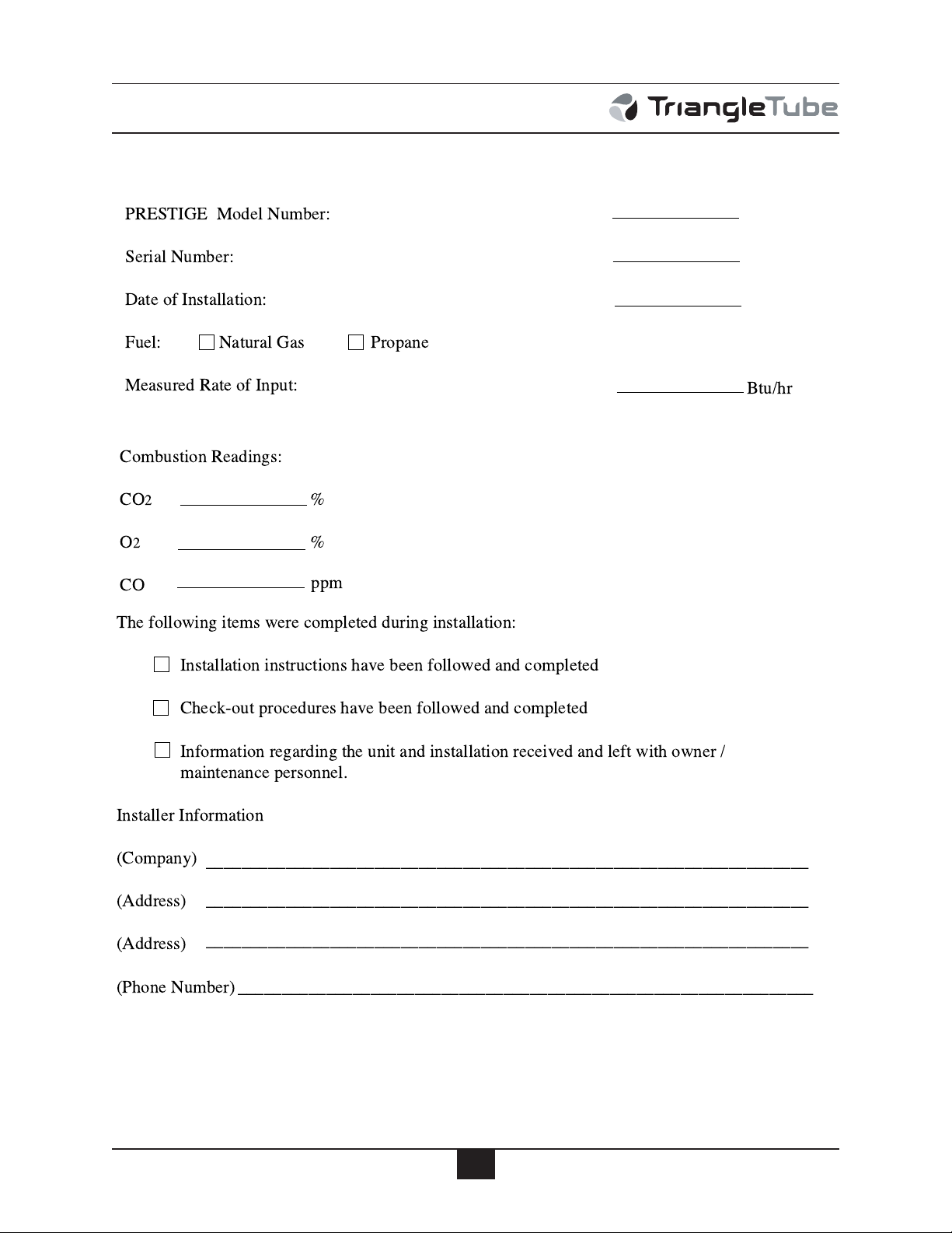
Installation Record
PRESTIGE Model Number:
Serial Number:
Date of Installation:
Fuel: Natural Gas Propane
Measured Rate of Input:
Combustion Readings:
CO
2
O2
CO
The following items were completed during installation:
Installation instructions have been followed and completed
Check-out procedures have been followed and completed
Information regarding the unit and installation received and left with owner /
maintenance personnel.
Installer Information
(Company)
(Address)
(Address)
(Phone Number)
Btu/hr
____________________________________________________________________
____________________________________________________________________
____________________________________________________________________
_________________________________________________________________
%
%
ppm
SECTION XV - Installation Record
67
Page 74
Maintenance Schedules
SECTION XVI - Maintenance Schedule
Service Technician
At least on an annual basis the following maintenance should be performed by a qualified service technician:
General
- Attend to any reported problems.
- Inspect the interior of the boiler jacket area;
clean and vacuum if necessary.
- Clean the condensate drain assembly and
fill with fresh water.
- Check boiler water pH on systems with
inhibitors and/or antifreeze.
- Check for leaks: water, gas, flue and condensate.
- Verify flue vent piping and air inlet piping
are in good condition, sealed tight and
properly supported.
- Check boiler water pressure, piping and
expansion tank.
Owner Maintenance
Periodically:
- Check the area around the unit.
- Check and remove any blockage from the
combustion air inlet and ventilation openings.
- Check the temperature and pressure
gauges.
Monthly:
- Check vent piping.
- Check combustion air inlet piping.
- Check the pressure relief valve.
- Check the condensate drain system.
Every 6 months:
- Check boiler piping and gas supply piping
for corrosion or potential signs of leakage.
- Operate the pressure relief valve.
- Check control settings.
- Check ignition electrode (sand off any
white oxide; clean and reposition).
- Check ignition wiring and ground wiring.
- Check all control wiring and connections.
- Check burner flame pattern (stable and uniform).
Additional items if combustion or performance
is poor:
- Clean heat exchanger and flue ways.
- Remove burner assembly and clean burner
head using compressed air only.
Once the maintenance items are completed,
review the service with the owner.
WARNING
Follow the maintenance procedures
given throughout this manual. Failure
to perform the service and maintenance
or follow the directions in this manual
could result in damage to the PRESTIGE Solo or in system components,
resulting in severe personal injury, death
or substantial property damage.
68
Page 75
Maintenance Procedures
SECTION XVII- Maintenance
Procedures
Maintenance Procedures
WARNING
The PRESTIGE Solo should be inspected and serviced annually, preferably at
the start of the heating season, by a qualified service technician. In addition, the
maintenance and care of the unit as outlined on page 68 and further explained
on pages 69 through 74 should be performed to assure maximum efficiency
and reliability of the unit. Failure to service and maintain the PRESTIGE Solo
and the system components could result
in equipment failure, causing possible
severe personal injury, death or substantial property damage.
NOTICE
The following information provides
detailed instruction for completing the
maintenance items outline in the maintenance schedule on page 68. In addition
to this maintenance, the PRESTIGE
Solo should be serviced at the beginning
of the heating season by a qualified service technician.
Reported Problems
Verify that combustion air inlet area is free of
any contaminates. Refer to the materials listed
on page 5 of this manual. If any of these products are in the area from which the unit takes
its combustion air, they must be removed
immediately or the combustion air intake must
be relocated to another area.
Inspect Burner Area
Remove the boiler front jacket panel and venturi inlet elbow.
Vacuum any dirt or debris from the
burner/blower components.
Re-install venturi inlet elbow and front jacket
panel when completed.
WARNING
Do not use solvents to clean any of the
burner components. The components
could be damaged, resulting in unreliable or unsafe operation.
Check System Piping
Inspect all piping (water and gas) on the boiler
system for leaks and verify that the piping is
leak free and properly supported.
Inspect the fittings and components on the unit
and verify they are leak free.
Any problems reported by the owner should be
checked, verified and corrected before proceeding with any maintenance procedures.
Check Surrounding Area
Verify that the area surrounding the PRESTIGE Solo is free of combustible / flammable
materials or flammable vapors or liquids.
Remove immediately if found.
WARNING
Eliminate all boiler water system leaks.
Continual fresh make-up water will
reduce the heat exchanger life causing
boiler failure. Leaking water may also
cause severe property damage to the surrounding area. Inspect the gas supply
piping using the procedure outlined on
Page 60.
69
Page 76

Maintenance Procedures
Clean Condensate Drain Assembly
1. Loosen the retaining nut from the condensate drain assembly and disconnect the
assembly from the boiler.
2. Empty any water from the trap and drain
assembly. Flush with fresh water as necessary to clean.
3. Check the drain piping from the condensate
drain assembly to the drain. Flush to clean
as necessary.
4. Reassemble the condensate drain assembly
onto the boiler by tightening the retaining
nut with rubber seal onto the boiler. Hand
tight only.
5. Remove the fill plug on the condensate drain
assembly and fill with water. See Fig. 14 on
page 25.
6. Replace the fill plug on drain assembly.
Check Ventilation Air Openings
Verify that all ventilation openings to the
mechanical room or building are open and
unobstructed. Check the operation and wiring
of any automatic ventilation dampers.
WARNING
Failure to inspect the vent system and
combustion air inlet piping and to have
any conditions repaired, can result in
severe personal injury or death.
Check Boiler System
Verify all system components are correctly
installed and operating properly.
Check the cold fill pressure for the system, typical cold water fill pressure is 12 psig.
Verify the system pressure, as the unit operates at
high temperature, to ensure the pressure does not
exceed 25 psig. Excessive pressure reading indicates expansion tank sizing is incorrect or system
performance problems.
Inspect air vent and air separators in the system. Remove the caps on automatic air vents
and briefly depress the valve stem to flush
vent. Replace the cap when completed. Ensure
vents do not leak, replace any leaking vents.
Verify boiler water pH level is between 6.0 and
8.0.
Check and verify the vent discharge and the
combustion air intake are free of debris and
obstructions.
Inspect Vent and Combustion Air Piping
Visually inspect the venting system and combustion air piping for blockage, deterioration
or leakage. Repair any deficiencies.
Verify that the combustion air inlet piping is
connected, sealed and properly supported.
Check and verify inhibitor /antifreeze concentration within the boiler water meets
inhibitor/antifreeze manuafacturer’s specifications.
If necessary contact a boiler water treatment
company for a chemical analysis.
70
Page 77

Maintenance Procedures
Check Expansion Tank
Refer to Section IV - Boiler Piping for recommended location of the expansion tank
and air eliminators.
Closed -Type Tank:
- Ensure tank is partially filled with
water leaving an air gap as a cushion.
Refer to the manufacturer’s instruction
for proper fill level.
- Ensure the tank is fitted with a device
that reduces gravity circulation of airsaturated tank water back into the system. This device prevents air from
bubbling up through the water as it
returns from the system.
- Ensure no automatic air vents are used
in the system. This will allow air to
escape from the system instead of
returning to the tank.
Diaphragm Tank:
- Ensure the system contains a minimum of
one automatic air vent. Recommended
location of the air vent should be atop an
air eliminator.
- Remove the tank from the system and
check the charge pressure. For residential applications the charge pressure is
typically 12 psig. If tank does not hold
a charge pressure, then the membrane is
damaged and the tank should be
replaced.
WARNING
Before manually operating the pressure
relief valve, ensure the discharge piping is
directed to a suitable place of disposal to
avoid a potential scald hazard. The discharge piping must be full size without
restriction and installed to permit complete drainage of both the valve and line.
If after closing the valve, the valve fails to seat
properly or continually weeps, replace the
relief valve. Ensure the cause of the relief
valve to weep is the valve itself, not due to system over-pressurization caused by an expansion tank that is waterlogged or undersized.
Inspection of Ignition Electrode
Remove the ignition electrode from the burner
mounting plate.
Remove any white oxides accumulated on the
electrode using fine grit sandpaper or steel wool.
If the electrode does not clean to a satisfactory
condition, replace the ignitor .
When replacing the ignition electrode, ensure
the gasket is in good condition and correctly
positioned, replace gasket if necessary.
Check Ignition Wiring and Ground Wiring
Inspect the ignition cable from the ignitor to
the TriMax control module.
Check Boiler Relief Valve
Inspect the relief valve and lift the lever to verify flow at least annually or as recommended
on the warning tag of the valve.
Inspect the ground wire from the ignitor to the
boiler jacket ground terminals.
Ensure wiring is in good condition and securely connected.
Check ground continuity of the wiring to the
boiler jacket or piping using a continuity meter.
Replace and correct ground wire if ground continuity is not completed and satisfactory.
71
Page 78

Maintenance Procedures
Check Control Wiring
Inspect all control wiring. Ensure wiring is in
good condition and properly connected.
Check Control Settings
1. Review all boiler settings in the Heating &
DHW EZ Setup menus. Adjust settings as
necessary, see page 46-49
2. Check any external limit control settings (if
used). Adjust settings as necessary.
Perform Start-up and Checkout Procedures
Start the unit and perform the start-up procedure as listed in this manual.
Verify the cold water fill pressure is correct and
the operating pressure of the boiler is within
normal operating range.
Complete the checkout procedures as referenced in this manual.
Check Burner Flame
Carefully remove the burner mounting plate
assembly from the heat exchanger. Ensure
combustion chamber insulation is not damaged
during removal of burner mounting plate
assembly. See WARNING on page 74.
Remove the burner head mounting screws and
remove the burner head. Inspect the burner
head for deterioration. Use compressed air or
a vacuum to clean the burner head.
Remove the venturi and gas valve assembly
from the blower.
Use a vacuum cleaner or compressed air to
clean the interior of the blower assembly.
Inspect the blower blades to ensure they are
clean and not damaged.
Re-assemble the venturi and gas valve onto the
blower. Ensure the venturi gasket is in good
condition, positioned correctly and replace gasket if necessary.
Re-assemble the burner head onto the burner
mounting plate. Ensure the burner head gasket
is in good condition, positioned correctly and
replace gasket if necessary.
Inspect the burner flame through the observation port on the heat exchanger.
If flame pattern is not fully blue and covers the
entire burner surface during high fire, shut the
unit down and allow it to cool thoroughly before
disassembly.
Close the external manual gas valve on the gas
supply line and disconnect the gas piping and
gas valve wire harness connector.
Disconnect the wiring harness connectors from
the blower and remove the blower retaining
screws or nuts. Remove the blower from the
unit.
Remove the mounting nuts securing the burner
mounting plate to the heat exchanger and set
aside.
Re-assemble the burner mounting plate assembly onto the heat exchanger. Ensure the burner
plate gasket and combustion chamber insulation is in place and not damaged, replace gasket and insulation if necessary. See WARNING
on page 74.
Re-assemble the blower onto the burner
mounting plate and reconnect the wiring harness connectors.
Re-assemble the gas supply connection and
wire harness to gas valve. Open the external
manual gas valve. Check gas piping for any
leaks as outlined on page 58 and repair if necessary. Place the unit back into service.
72
Page 79

Maintenance Procedures
Check Flame Signal
The flame signal can be read from the Boiler
Information screen. It should be a min. 1μ Α
−DC.
Check the ignitor for fouling or damaged
insulation if a low flame signal is read.
Check ground wiring and continuity as a cause
for low flame signal. Replace ignitor if conditions are satisfactory.
Check Combustion Levels
Refer to page 60 of this manual for measuring
combustion levels and burner adjustments.
Check Flue Gas Temperature
1. Manually place the boiler into high fire.
See page 60 for procedure.
2. Navigate to the Boiler Information Menu
to observe the flue gas temperature. See
page 50 for procedure.
3. If the flue gas temperature is more than 54°F
[30°C] above the supply water temperature,
shut the boiler down and follow the heat
exchanger cleaning procedure below.
Clean Heat Exchanger
1. Shut down the boiler:
- Follow the instructions on Page 62 "To
Turn Off Gas to Appliance"
- Do not drain the boiler unless the boiler will be subject to freezing conditions.
- Do not drain the boiler if freeze protection fluid is used in the system.
2. Allow the boiler to cool down to room temperature before servicing.
3. Disconnect the gas piping and gas valve
wire harness connector.
4. Disconnect the wiring harness connectors
from the blower and remove the blower
retaining screws or nuts. Remove the blower from the unit.
5. Remove the mounting nuts securing the
burner mounting plate to the heat exchanger and set aside.
6. Carefully remove the burner mounting
plate assembly from the heat exchanger.
Ensure combustion chamber insulation is
not damaged during removal of burner
mounting plate assembly. See WARNING
on page 74.
7. Carefully remove the combustion chamber
insulation from the heat exchanger and set
aside. See WARNING on page 74.
8. Use a vacuum cleaner, compressed air or
water to remove any accumulation from
the heat exchanger flue ways. Do not use
any solvent.
9. Re-install the combustion chamber insulation onto the heat exchanger.
10. Re-assemble the burner mounting plate
assembly onto the heat exchanger. Ensure
the burner plate gasket and combustion
chamber insulation is in place and not damaged, replace gasket and insulation if necessary. See WARNING on page 74.
11. Re-assemble the blower onto the burner
mounting plate and reconnect the wiring
harness connectors.
12. Reconnect the gas piping and wire harness
to gas valve. Check for leaks, repair if necessary.
13. Close isolation valves on the boiler water
piping to isolate the boiler from the heating
system.
14. Attach a hose to the boiler drain valve and
flush the boiler thoroughly with fresh
water by using the purge valves to allow
water to enter through the make-up water
line to the boiler.
73
Page 80
Maintenance Procedures
15. Once the boiler has been completely
flushed, return the boiler and system piping
back to operation.
16. Perform the required startup and checkout
procedures as outlined on pages 56 to 66.
Handling Previously Fired Combustion Chamber Insulation
WARNING
The combustion chamber insulation
contains ceramic fibers, which are classified as a possible human carcinogen.
When exposed to extremely high temperatures, the ceramic fibers, which
contain crystalline silica, can be converted into cristobalite.
Avoid Breathing and Contact with Skin
and Eyes
Review With Owner
Ensure the owner understands the importance to perform the maintenance schedule
specified in this manual.
Remind the owner of the importance to call
a licensed contractor should the unit or system exhibit any unusual behavior.
2. Wear long sleeved, loose fitting clothing,
gloves and eyes protection.
3. Assure adequate ventilation.
4. Wash with soap and water after contact.
5. Wash potentially contaminated clothes
separately from other laundry and rinse
washing machine thoroughly.
6. Discard used insulation in an air tight
plastic bag.
When removing or repairing the combustion
chamber insulation follow these precaution
measures:
1. Use a NIOSH approved respirator which
meets OSHA requirements for cristobalite
dust, similar to N95. Contact NIOSH at
1-800-356-4676 or on the web at
www.cdc.gov/niosh for latest recommendations.
NIOSH Stated First Aid:
Eye/Skin: Immediately irrigate
Breathing: Clean fresh air
74
Page 81
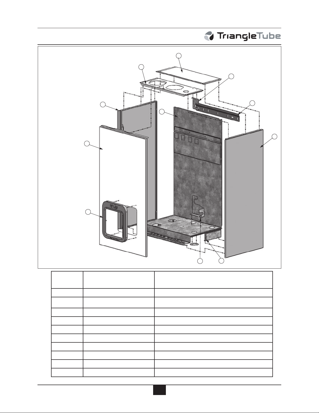
Replacement Parts
4
7
9
10
3
4
2
5
1
6
8
Fig. 33: PRESTIGE Solo 60 Jacket Components
Item Part # Description
1 PTJKT10R Rear Panel
2 PTJKT08F Front Jacket Panel
3 PTRKIT129 Control Enclosure Bezel
4 PTJKT22S Side Jacket Panel (Left or Right)
5 PTJKT14T Top Jacket Panel
6 PTJKT18T Top Jacket Access Panel
7 PSRKIT21 Wall Mounting Bracket with Hardware
8 PTJKTSUP02 Support - Boiler Supply Piping
9 PTJKTSUP03 Support - Boiler Return Piping
10 PTJKTSUP01 Support - Jacket
75
Page 82
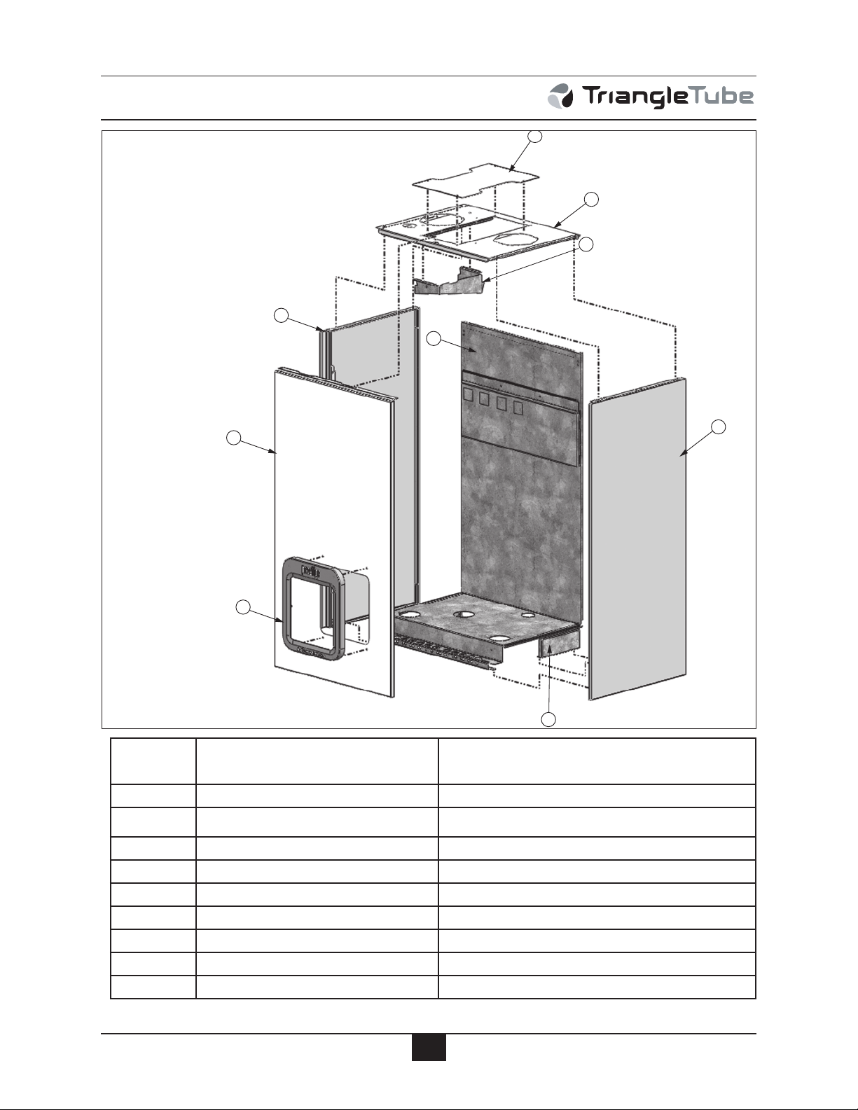
Replacement Parts
4
9
3
4
2
5
1
6
8
Fig. 34: PRESTIGE Solo 175/250 Jacket Components
Item Part # Description
1 PTJKT12R Rear Panel
2 PTJKT08F Front Jacket Panel
3 PTRKIT129 Control Enclosure Bezel
4 PTJKT22S Side Jacket Panel (Left or Right)
5 PTJKT17T Top Jacket Panel
6 PTJKT20T Top Jacket Access Panel
7 PSRKIT21 Wall Mounting Bracket with Hardware (Not Shown)
8 PTJKT21D Combustion Air Deflector
9 PTJKTSUP01 Support - Jacket
76
Page 83
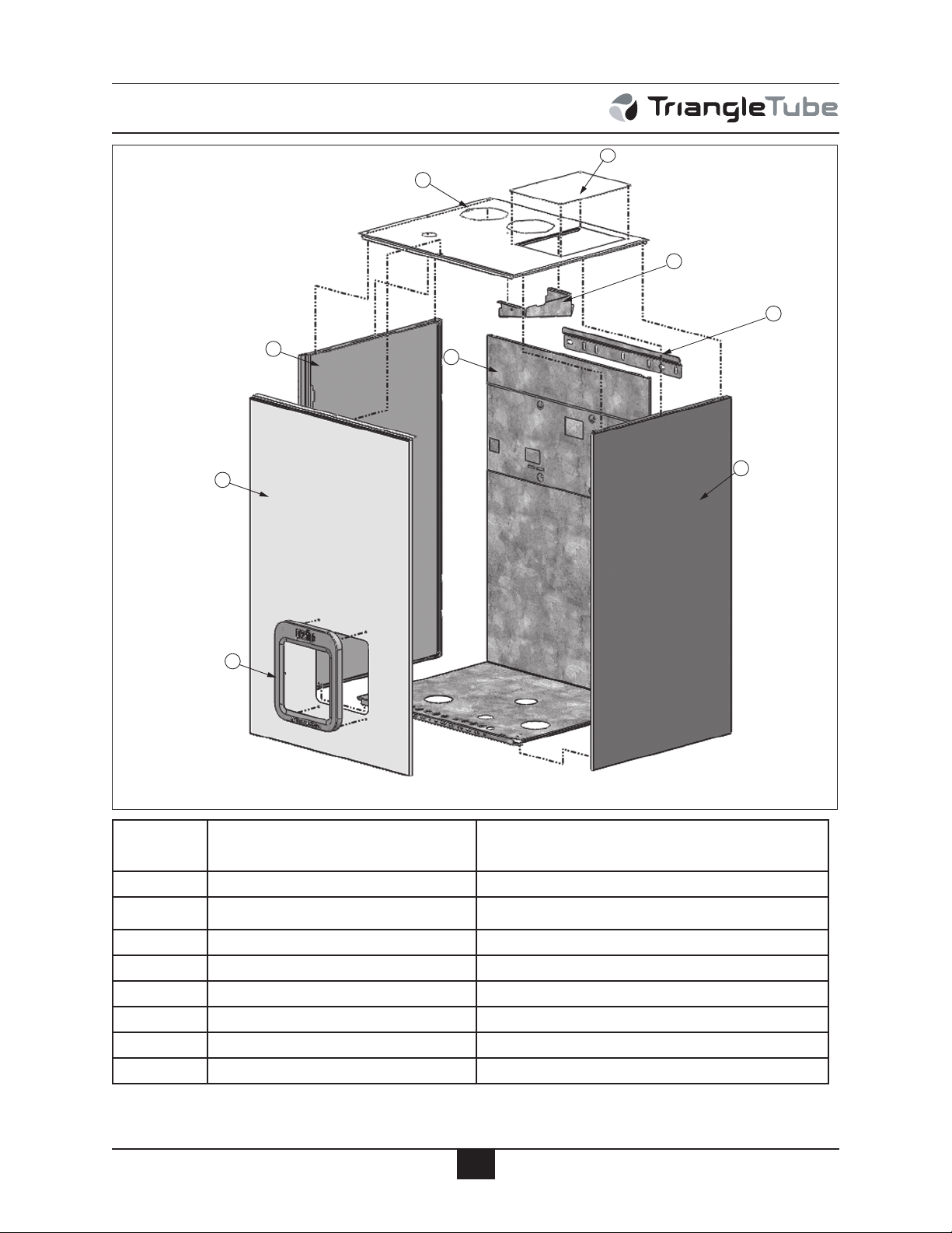
Replacement Parts
4
3
4
2
5
1
6
8
7
Fig.35: PRESTIGE Solo 399 Jacket Components
Item Part # Description
1 PTJKT13R Rear Panel
2 PTJKT09F Front Jacket Panel
3 PTRKIT129 Control Enclosure Bezel
4 PTJKT23S Side Jacket Panel (Left or Right)
5 PTJKT16T Top Jacket Panel
6 PTJKT21T Top Jacket Access Panel
7 PSRKIT21 Wall Mounting Bracket with Hardware
8 PTJKT21D Combustion Air Deflector
77
Page 84
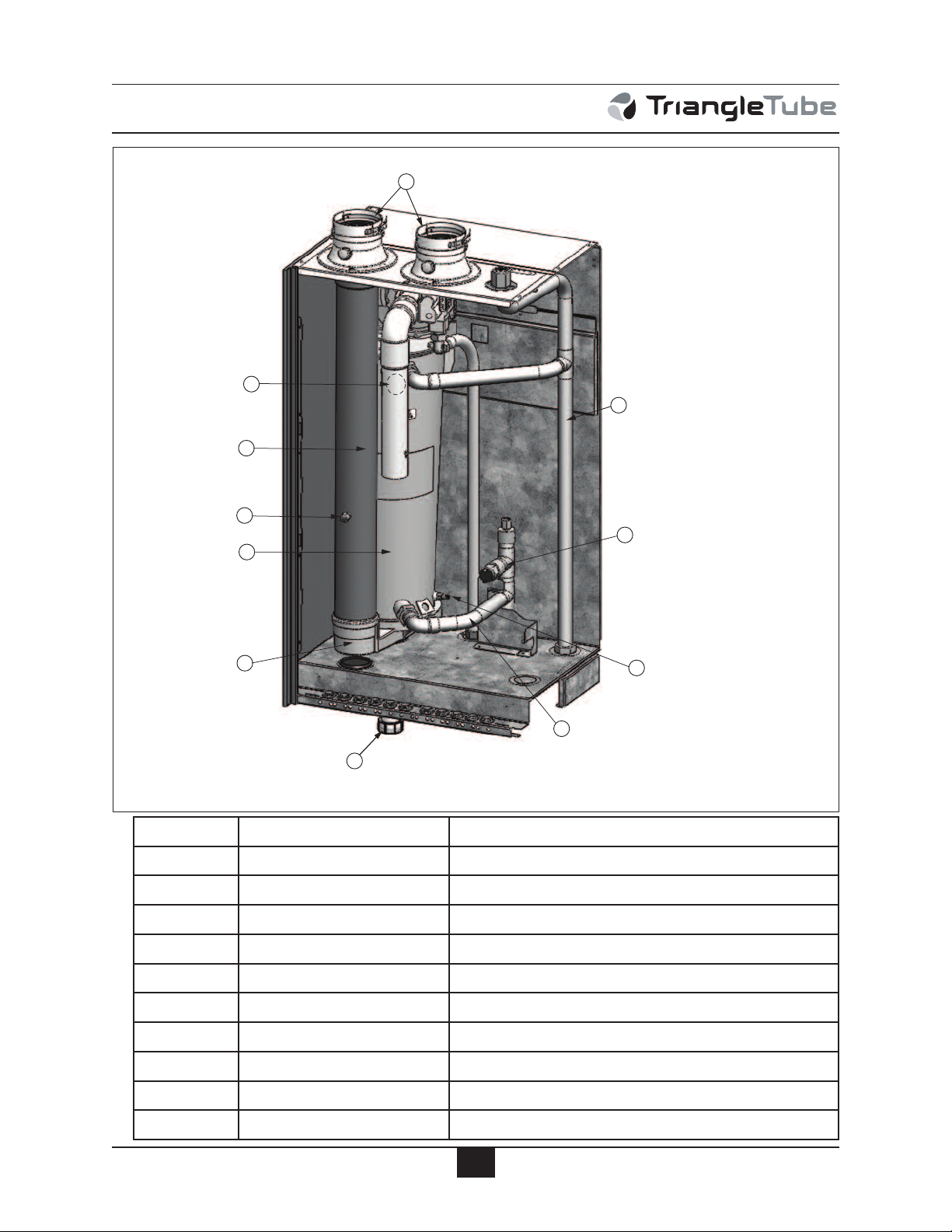
Replacement Parts
9
8
4
6
2
4
7
1
10
3
5
Fig. 36: PRESTIGE Solo 60 Internal Components
Item Part # Description
1 PTRKIT124 Heat Exchanger Body
2 PTADPT07 Vent Outlet/ Combustion Air Inlet Adapter
3 PTRKIT115 Polypropylene Vent Pipe
4 PTRKIT122 Supply / Return Temperature Sensor
5 PTRKIT123 Flue Temperature Sensor
6 PGRKIT20 LWCO Pressure Device
7 PSRKIT05 Condensate Drain Assembly
8 PSRKIT06 Boiler Piping - Return Assembly
9 PSRKIT52 Boiler Piping - Supply Assembly
10 PTRKIT119 Polyproplylene Condensate Pan
78
Page 85
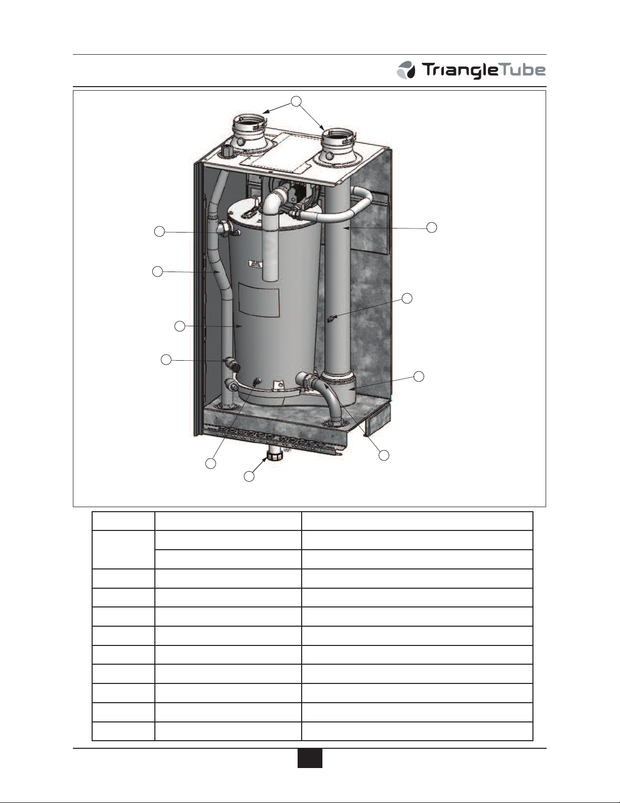
Replacement Parts
9
8
4
6
2
4
7
1
3
5
10
Fig. 37: PRESTIGE Solo 175/250 Internal Components
Item Part # Description
1
PTRKIT127 Heat Exchanger Body Solo 250
2 PTADAPT07 Vent Outlet/ Combustion Air Inlet Adapter
PTRKIT126 Heat Exchanger Body Solo 175
3 PTRKIT116 Polypropylene Vent Pipe
4 PTRKIT122 Supply / Return Temperature Sensor
5 PTRKIT123 Flue Temperature Sensor
6 PGRKIT20 LWCO Pressure Device
7 PSRKIT05 Condensate Drain Assembly
8 PSRKIT28 Boiler Piping - Return Assembly
9 PSRKIT29 Boiler Piping - Supply Assembly
10 PTRKIT120 Polyproplylene Condensate Pan
79
Page 86
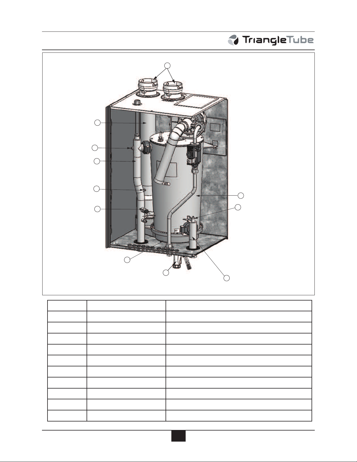
Replacement Parts
4
8
3
6
2
7
9
5
1
4
10
Fig. 38: PRESTIGE Solo 399 Internal Components
Item Part # Description
1 PTRKIT128 Heat Exchanger Body
2 PTADPT08 Vent Outlet/ Combustion Air Inlet Adapter
3 PTRKIT117 Polypropylene Vent Pipe
4 PSRKIT47 Supply / Return Temperature Sensor
5 PTRKIT123 Flue Temperature Sensor
6 PGRKIT20 LWCO Pressure Device
7 PSRKIT05 Condensate Drain Assembly
8 PSRKIT48 Boiler Piping - Return Assembly
9 PSRKIT49 Boiler Piping - Supply Assembly
10 PTRKIT121 Polypropylene Pan
80
Page 87
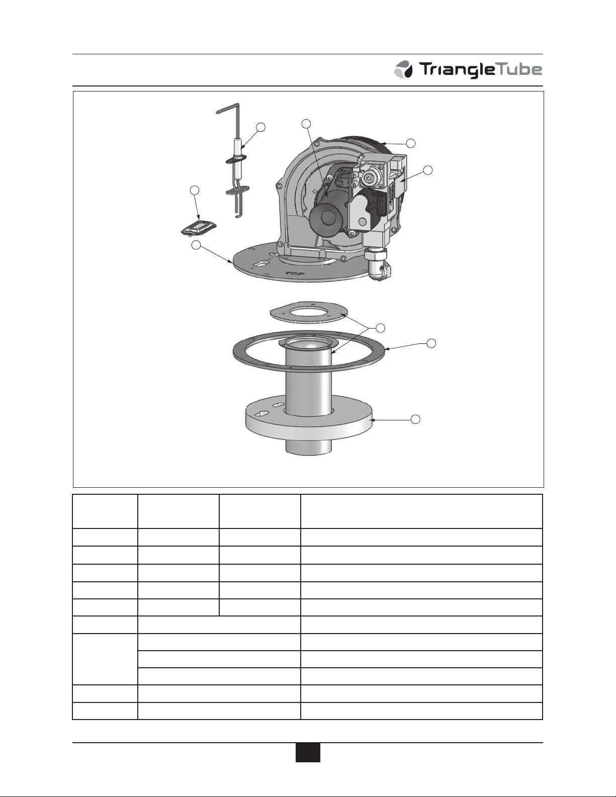
7
2
5
4
1
3
9
6
8
Replacement Parts
Fig. 39: PRESTIGE Solo 60/175/250 Burner Components
Item
PRESTIGE
Solo 60
1 PSRKIT09 PSRKIT30 Combustion Chamber Insulation
2 PSRKIT11 PSRKIT31 Burner Head with Gasket
Part #
3 PTRKIT114 PSRKIT13 Blower with Gasket
4 PSRKIT12 PSRKIT32 Burner Plate
5 PSGSK15 PSGSK16 Burner Plate Gasket
6 PTRKIT111 Gas Valve
PSRKIT80 Venturi - 055 Solo 60
7
PSRKIT82 Venturi - 052 Solo 175
PSRKIT83 Venturi - 051 Solo 250
8 PTRKIT113 Igniter and Cable with Gasket
9 PSRKIT16 Sight Glass Assembly (Glass, Gasket and Bracket)
Part #
PRESTIGE
Solo 175-250
Description
81
Page 88
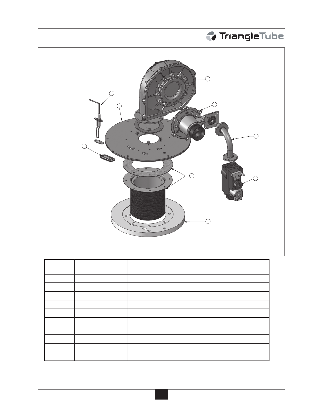
Replacement Parts
7
2
10
4
1
3
9
7
6
8
Fig. 40: PRESTIGE Solo 399 Burner Components
Item Part # Description
1 PSRKIT37 Combustion Chamber Insulation
2 PSRKIT38 Burner Head with Gasket
3 PSRKIT40 Blower with Gasket
4 PSRKIT39 Burner Plate
5 PSGSK17 Burner Plate Gasket (Not Shown)
6 PTRKIT112 Gas Valve
7 PSRKIT84 Venturi
8 PTRKIT113 Igniter and Cable with Gasket
9 PSRKIT16 Sight Glass Assembly (Glass, Gasket and Bracket)
10 PSRKIT42 Gas Valve Piping
82
Page 89
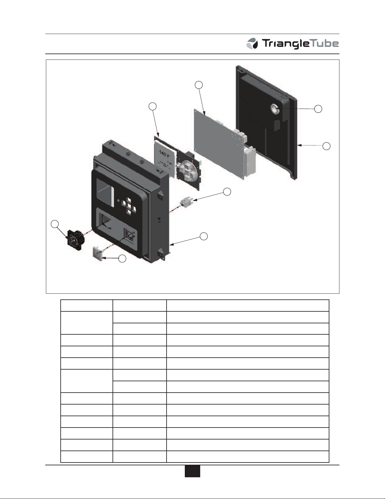
8
3
4
1
6
5
2
7
Replacement Parts
Fig. 41: PRESTIGE Solo Control Enclosure
Item Part # Description
PTRKIT109 Pressure Gauge and Fitting (All except Solo 399)
1
PTRKIT110 Pressure gauge and Fitting (Solo 399)
2 PTSWI01 Power Switch
3 PTSWI02 Power Switch Cover
4 PTRKIT108 Control Enclosure
PTRKIT105 TriMax Control Module (Solo 60, 110 &175)
5
PTRKIT106 TriMax Control Module (Solo 250 & 399)
6 PTRKIT107 TriMax Display Module
7 PTCON19 Control Enclosure Cover
8 PTGRO01 Igniter Cable Grommet
9 PTFUSE02 TriMax Control Module 5A Fuse (Not Shown)
10 PTFUSE01 Circulator 2.5A Fuses (Not Shown)
11 PTFUSE03 In-Line Voltage 8A Fuse (Not Shown)
83
Page 90
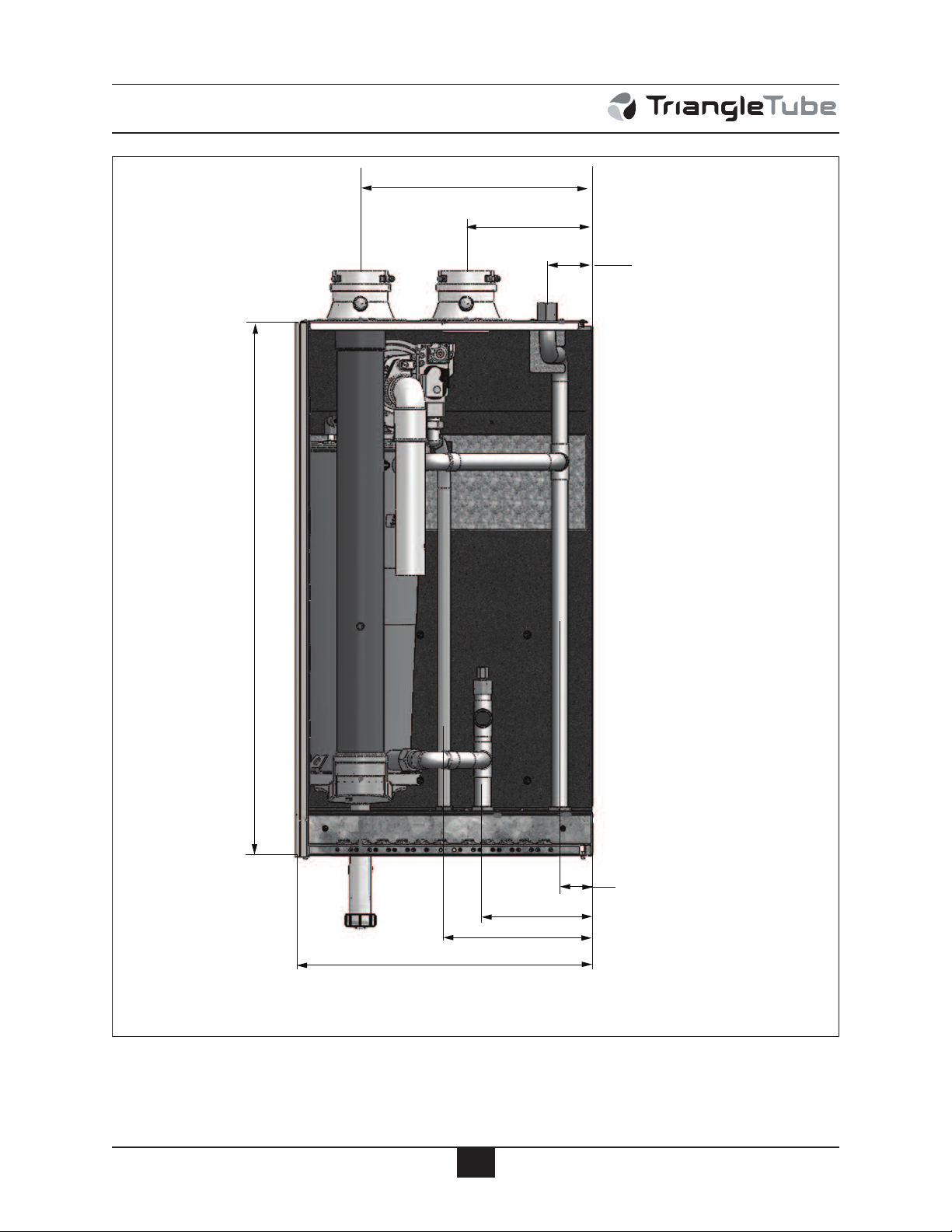
Product Specifications
35 1/2” [902 mm]
15 3/8” [392 mm]
8 1/2” [216 mm]
9 7/8” [251 mm]
2 1/4”
[56 mm]
3”
[76 mm]
1 ” NPT Boiler Supply
1/2” NPT Gas Connection
3/4” NPSC Pressure Relief Valve
3” Combustion AIr Inlet
3” Vent Outlet
19 3/4” [502 mm]
7 3/8” [186 mm]
1” NPT Boiler Return
Front View PRESTIGE Solo 60
84
Page 91
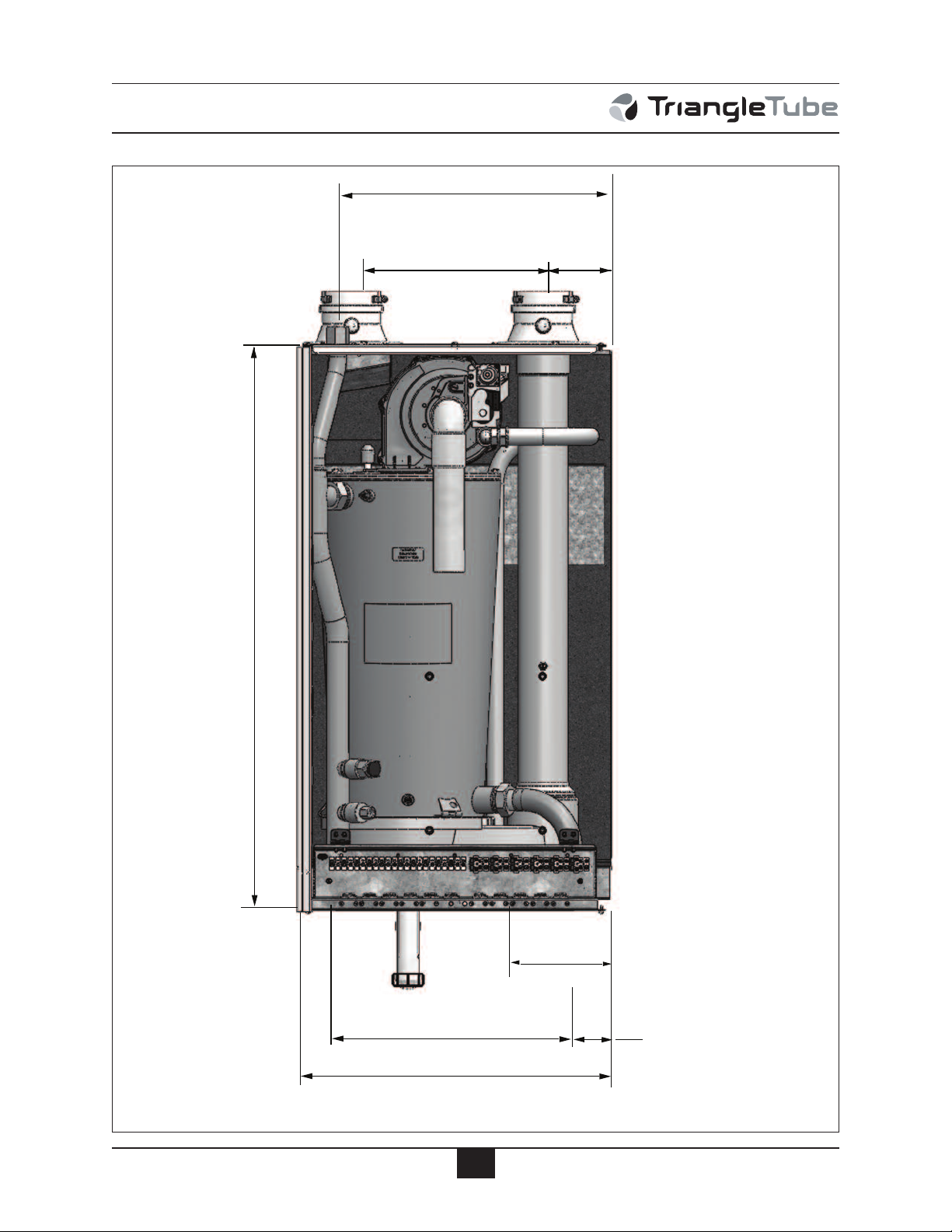
Product Specifications
35 1/2” [902 mm]
17 1/4” [437 mm]
12” [305 mm]
4 1/4”
[108 mm]
14 1/2” [368 mm]
2 3/4”
[70 mm]
19 3/4” [502 mm]
7 3/8”
[186 mm]
3/4” NPT Gas Connection
1-1/4” NPT Boiler Return
1-1/4” NPT Boiler Supply
3” Vent Outlet
3” Combustion AIr Inlet
3/4” NPSC Pressure Relief Valve
Front View PRESTIGE Solo 175/250
85
Page 92
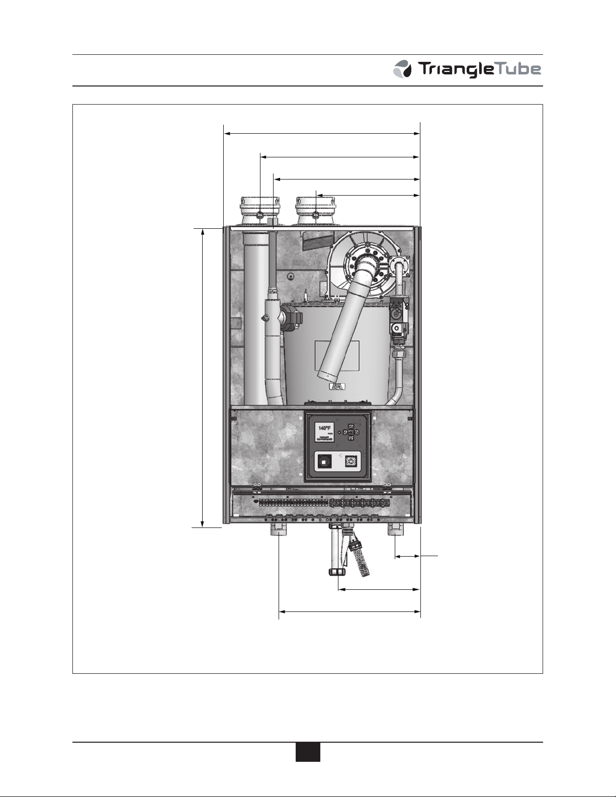
Product Specifications
37 1/2” [953 mm]
24 3/4” [628mm]
20 1/4” [516 mm]
18 5/8” [473 mm]
13 1/4” [340 mm]
9 1/4” [235 mm]
3 1/4”
[83 mm]
1 1/2” NPT Boiler Supply
1” Gas Connection
1 1/2” NPT Boiler Return
4” Combustion Air Inlet
3/4” NPSC Pressure Relief Valve
4” Vent Outlet
17 3/4” [454 mm]
Front View PRESTIGE Solo 399
86
Page 93
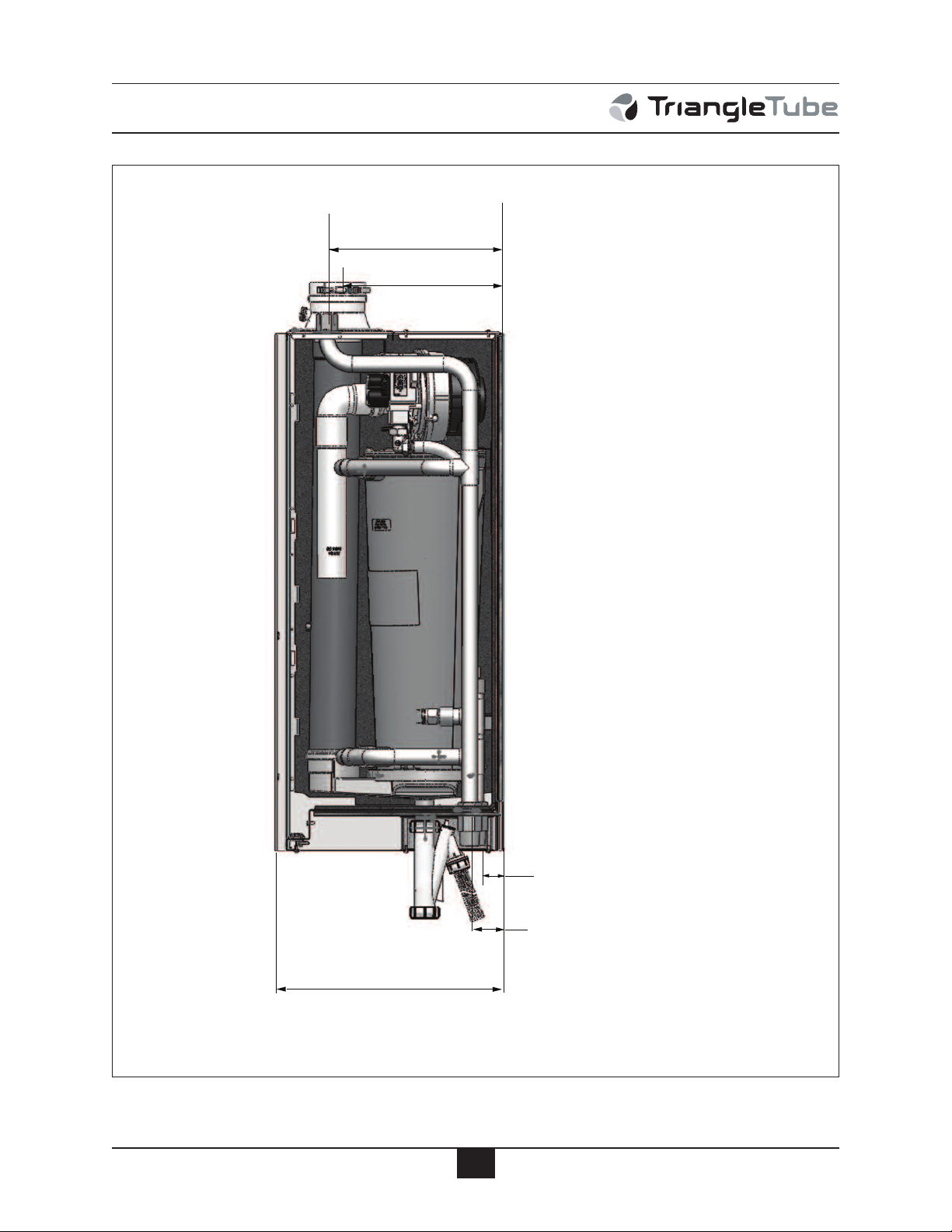
Product Specifications
11 3/8” [289 mm]
1 7/8”
[48mm]
15 5/8” [396 mm]
2 1/4”
[58mm]
12” [306 mm]
1” NPT Boiler Return
1” NPT Boiler Supply
1/2” NPT Gas Connection
3” Vent Outlet
3” Combustion AIr Inlet
3/4” NPSC Pressure Relief Valve
Side View PRESTIGE Solo 60
87
Page 94
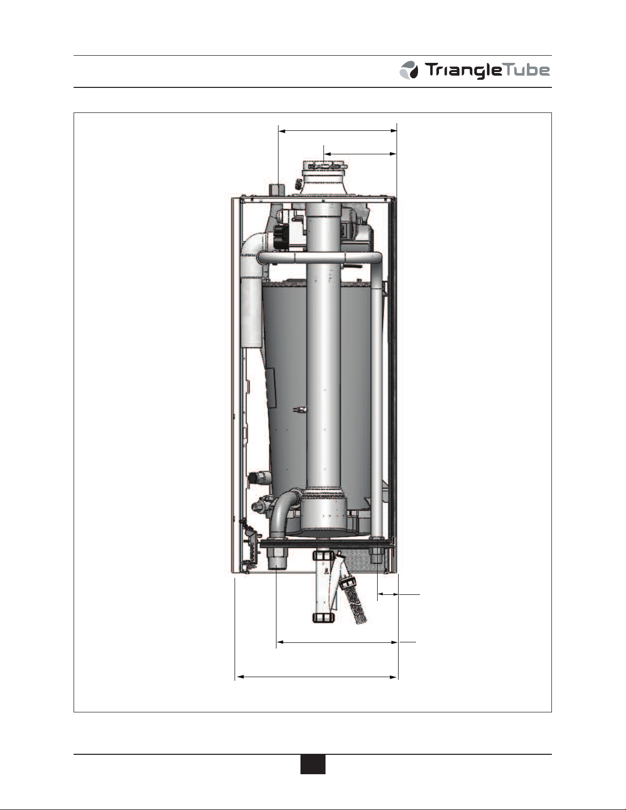
Product Specifications
11 3/8” [288 mm]
6 7/8” [176 mm]
11 3/8” [288 mm]
1 7/8”
[51 mm]
15 5/8” [396 mm]
3/4” NPT Gas Connection
1-1/4” NPT Boiler Supply
1-1/4” NPT Boiler Return
3” Vent Outlet
3” Combustion AIr Inlet
3/4” NPSC Pressure Relief Valve
Side View PRESTIGE Solo 175/250
88
Page 95
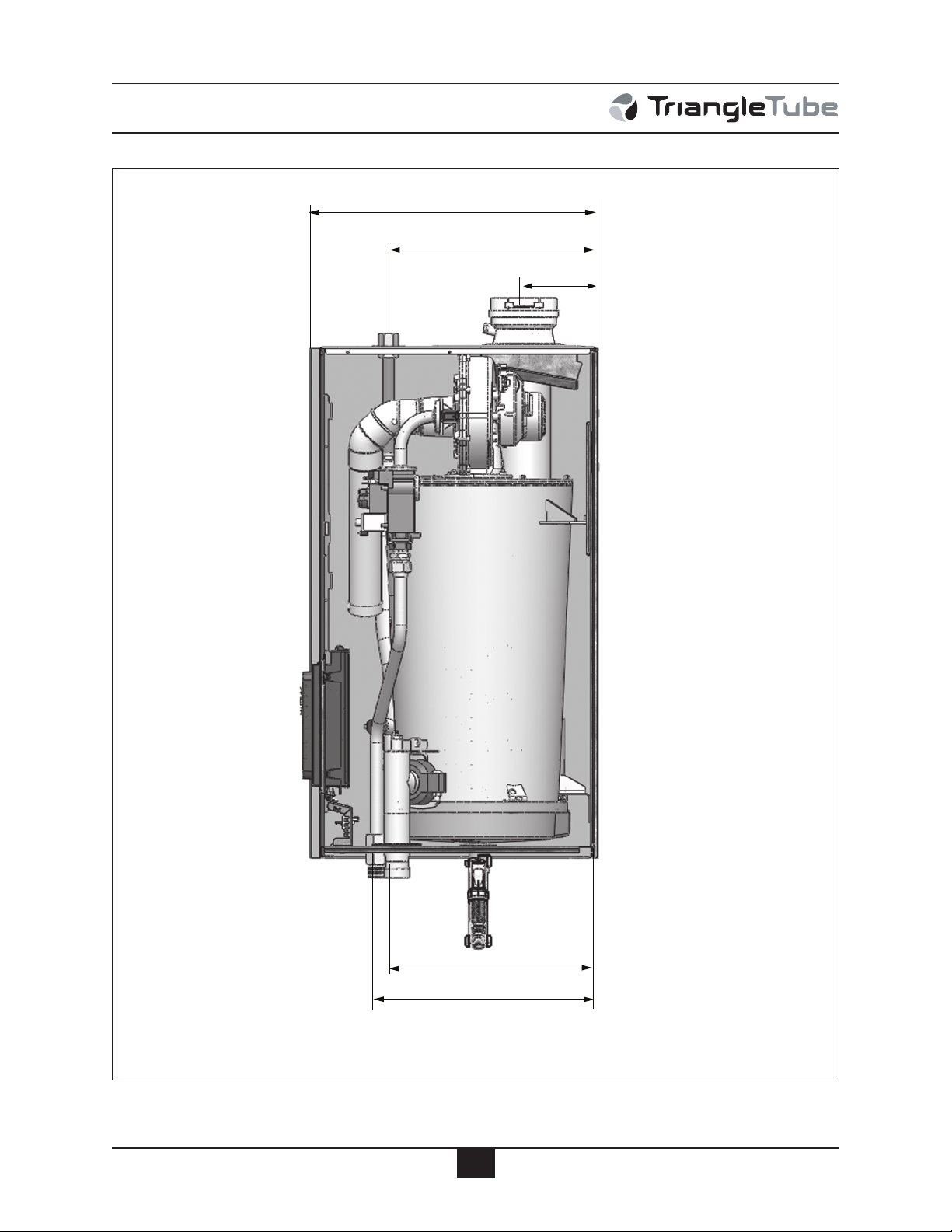
Product Specifications
21 1/4” [540 mm]
15 3/8” [390 mm]
14 3/4” [374 mm]
16 3/8” [416 mm]
5 7/8” [150 mm]
1 1/2” NPT Boiler Supply
1 1/2” NPT Boiler Return
1” Gas Connection
4” Combustion Air Inlet
4” Vent Outlet
3/4” NPSC Pressure Relief Valve
Side View PRESTIGE Solo 399
89
Page 96
Product Specifications
94.1%
95.1%
Fuel
Combustion
Efficiency
Input
Note 4
Output
Note 4
Note 5
Thermal
Efficiency
Net IBR
Rating
Note 2
Shipping
Weight
Lbs / Kg
Boiler
Model
379,000
399,000
330,000
225 / 102
Natural
SOLO 399
102,500
110,000
102,500
Propane
87,000
Fuel
DOE
Heating Capacity
Note 1 & 4
Input
Note 4
DOE Seasonal
Efficiency AFUE
Note 3
Net IBR
Rating
Note 2
60,000
96%
Shipping
Weight
Lbs / Kg
95 / 43
Natural
Boiler
Model
SOLO 60
47,000
110,000
102,500
96%
95 / 43
Propane
87,000
154,000
54,000
170,000
96%
131 / 60
Natural
SOLO 175
134,000
102,500
102,500
96%
131 / 60
Propane
Propane
87,000
223,000
245,000
96%
142 / 65
Natural
SOLO 250
194,000
102,500
110,000
102,500
96%
142 / 65
87,000
Note 1: The heating capacity of the PRESTIGE Solo
60/175/250 is based on the test requirements
of the U.S. Department of Energy.
Note 2: The IBR rating is based on a piping and pick
up allowance of 1.15. This allowance should
be sufficient for the standard radiation
requirements for a building load.
Note 3: Based on the given AFUE the PRESTIGE
Solo 60/175/250 meets the energy efficiency
guidelines established by Energy Star.
DOE
Note 4: Input and output ratings are shown for sea
level applications. The PRESTIGE Solo
automatically derates the input at approximately 2% for every 1,000 Ft. of altitude. No
alterations to the boiler or burner system is
required.
Note 5: PRESTIGE Solo 399 output rating is based
off of the thermal efficiency.
90
Page 97
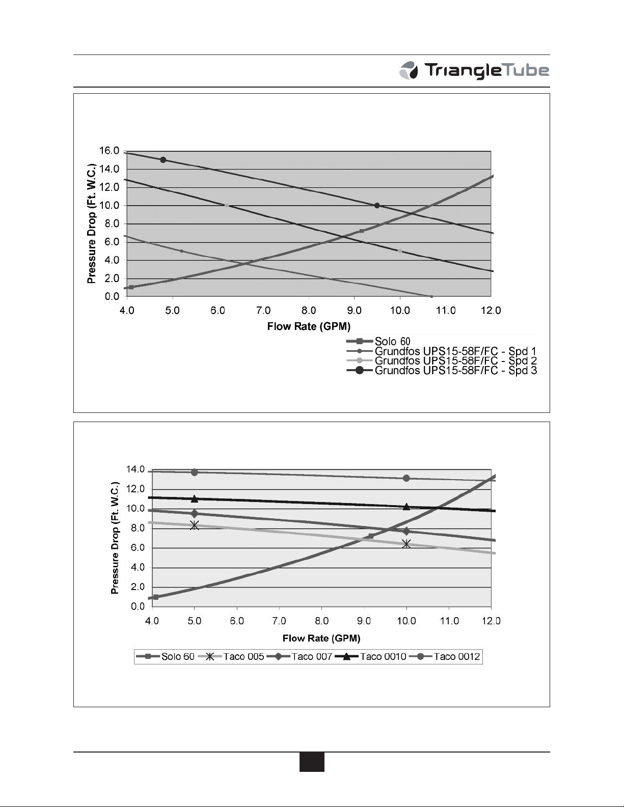
Product Specifications
Pressure Drop Comparison -Grundfos
Graph 2: Pressure Loss Through Boiler-Grundfos Circulator
Pressure Drop Comparison -Taco
Graph 3: Pressure Loss Through Boiler-Taco Circulators
Note: Minimum allowable flow rate at full input:
- 3 gpm SOLO 60
91
Page 98
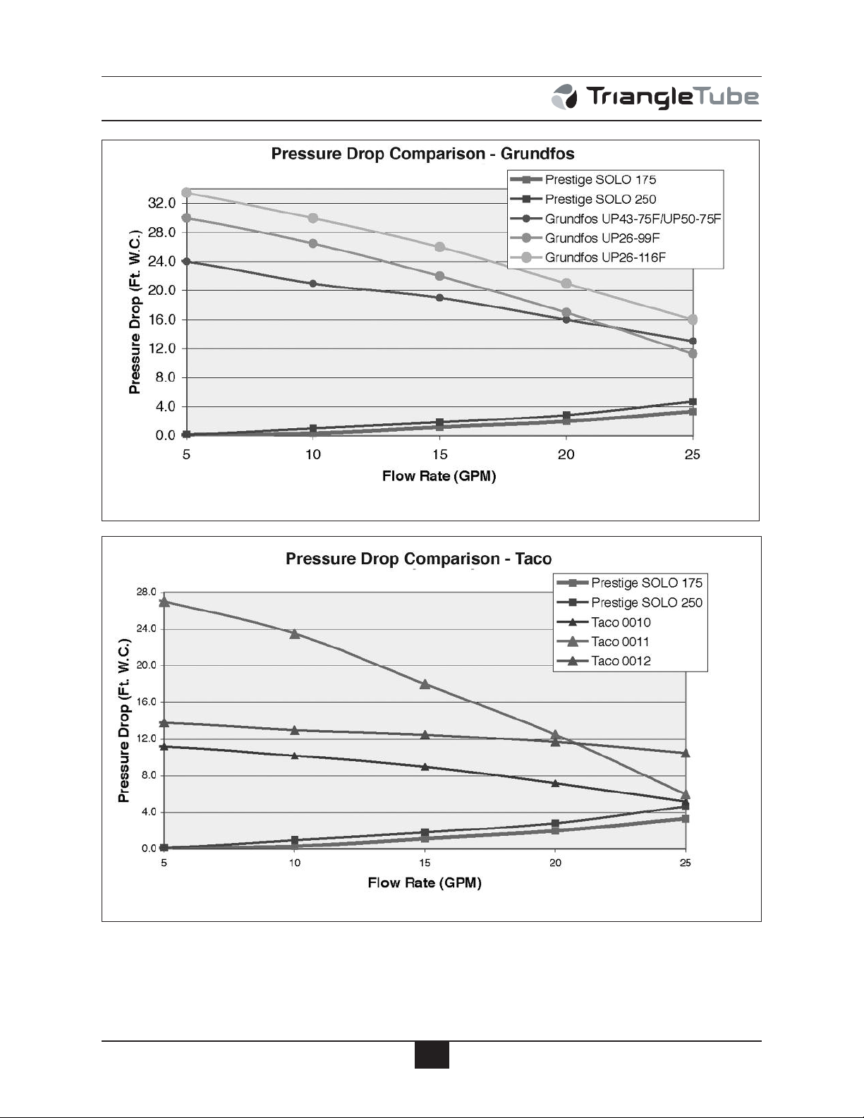
Product Specifications
Graph 4: Pressure Loss Through Boiler - Grundfos Circulators
Graph 5: Pressure Loss Through Boiler - Taco Circulators
Note: Minimum allowable flow rate at full input:
- 8 gpm SOLO 175
- 12 gpm SOLO 250
92
Page 99
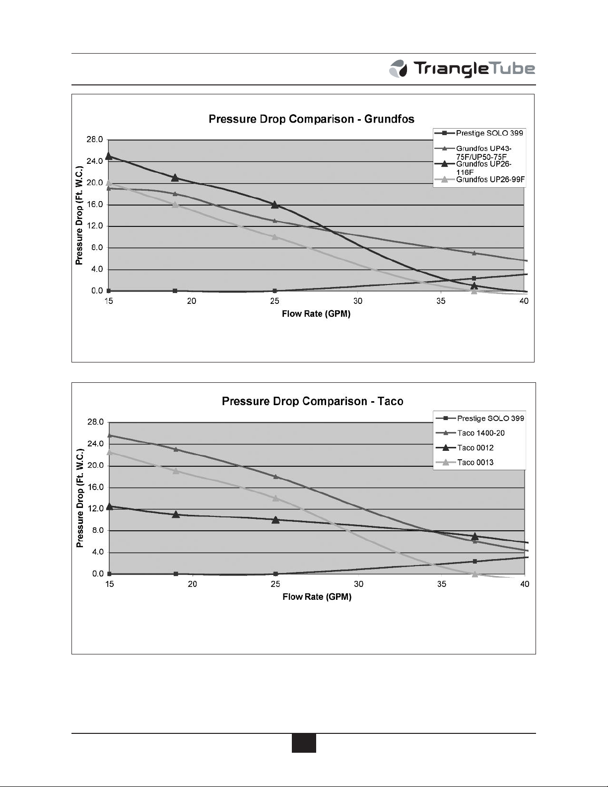
Product Specifications
Graph 6: Pressure Loss Through Boiler - Grundfos Circulators
Graph 7: Pressure Loss Through Boiler - Taco Circulators
Note: Minimum allowable flow rate at full input:
- 19 gpm SOLO 399
93
Page 100
Additional quality water heating equipment available
An
Company
from Triangle Tube
Maxi-Flo and Spa Heat Exchangers
SMART Indirect Fired Water Heaters
- Construction of high quality corrosion resistant
stainless steel (AISI 316) or titanium
- Specially designed built-in flow restrictor to assure
maximum heat exchange
- Compact and light weight
- Available in 5 sizes that can accommodate any size
pool or spa
TTP Brazed Plate Heat Exchangers
- Exclusive Tank-in-Tank design
- Stainless steel construction
- Available in 8 sizes and 2 models
- Limited LIFETIME residential warranty
- 15 year limited commercial warranty
- Self cleaning/self descaling design
- For domestic water, snow melting, radiant floor,
refrigeration
- Plates made of stainless steel, with a 99.9 % copper
and brazed, ensuring a high resistance to corrosion
- Self cleaning and self descaling
- Computerized sizing available from Triangle
Tube/Phase III
- Available in capacities from 25,000 BTU/hr to
5,000,000 BTU/hr
Freeway Center - 1 Triangle Lane - Blackwood, NJ 08012
Tel: (856) 228 8881 - Fax: (856) 228 3584
http://www.triangle tube.com
E-mail: Info@triangle tube.com
 Loading...