

Page 1
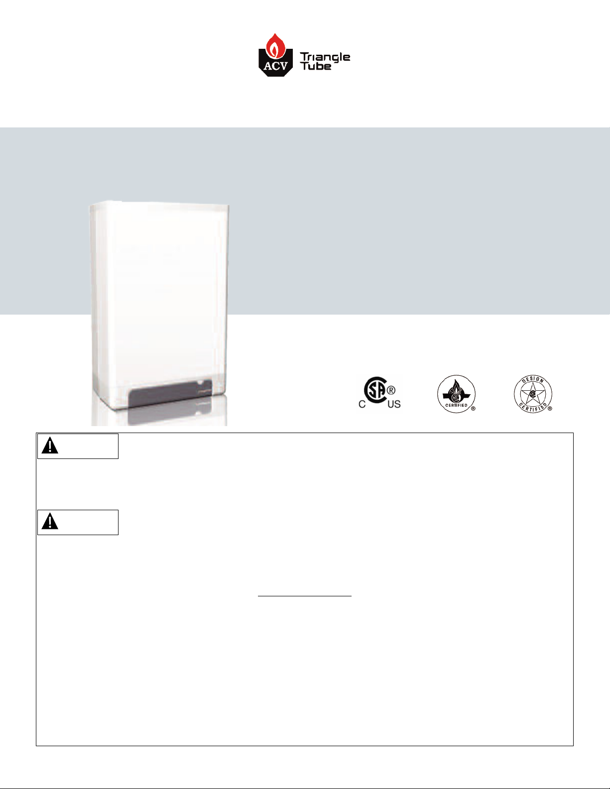
User’s Information Manual
CHALLENGER
COMBI
CC105, CC125, CC125H
WARNING
If the information in this manual is not followed exactly, a fire or explosion may result causing
property damage, personal injury, or death.
WARNING
To maintain the safety & longevity of your appliance, read and follow the maintenance schedule information throughout this manual.
FOR YOUR SAFETY
Do not store or use gasoline or other flammable vapors and liquids in the vicinity of this or any other•
appliance.
WHAT TO DO IF YOU SMELL GAS•
Do not try to light any appliance•
Do not touch any electrical switch; do not use any phone in your building.•
Immediately call your gas supplier from a neighbor’s phone. Follow the gas supplier’s instructions.•
If you cannot reach your gas supplier, call the fire department.•
Installation and service must be performed by a qualified installer, service agency or the gas supplier.•
Date: 10/6/2016 2016-41 Challenger COMBI User Manual
Page 2

Table of Contents
Section I: Product & Safety Information...............................................................................................................................1
1.1 Definitions ..................................................................................................................................................................1
.2 Safety Information .....................................................................................................................................................1
1
.3 Homeowners ..............................................................................................................................................................1
1
1.4 Warranty .....................................................................................................................................................................2
1.5 Service and Maintenance...........................................................................................................................................3
.6 CHALLENGER Operation............................................................................................................................................3
1
1.7 Appliance & System Water.........................................................................................................................................3
Section II: Combustion Air - Prevention of Contamination .................................................................................................4
2.1 Combustion Air Contamination.................................................................................................................................4
Section III: Maintenance Schedule ........................................................................................................................................5
3.1 Service Technician......................................................................................................................................................5
3.2 Owner Maintenance ...................................................................................................................................................5
Section IV: Maintenance Procedures.....................................................................................................................................6
4.1 Periodic Maintenance.................................................................................................................................................6
4.2 Monthly Maintenance ................................................................................................................................................6
4.3 6-Month Maintenance................................................................................................................................................7
Section V: Operating Instructions..........................................................................................................................................8
Section VI: Appliance Control Display ...................................................................................................................................9
6.1 Appliance ON/OFF .....................................................................................................................................................9
6.2 Units............................................................................................................................................................................9
6.3 Additional DHW Functions.........................................................................................................................................9
6.4 Setting the Appliance Parameters .............................................................................................................................11
6.5 Error Mode..................................................................................................................................................................12
6.6 Error Codes.................................................................................................................................................................13
6.7 Warning Codes ...........................................................................................................................................................13
Section VII: Replacement Parts..............................................................................................................................................14
7.1 Internal Components .................................................................................................................................................14
7.2 Front Door...................................................................................................................................................................15
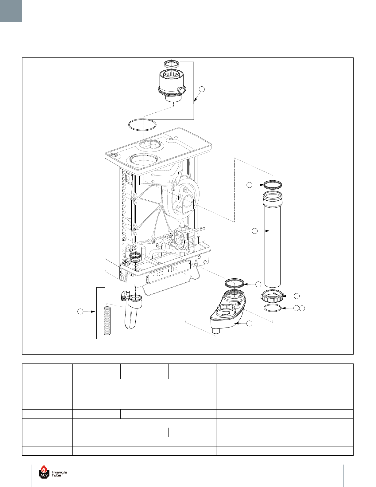
7.3 Vent Components.......................................................................................................................................................16
7.4 Heat Exchanger Components ....................................................................................................................................17
7.5 Blower & Gas Valve Components...............................................................................................................................18
7.6 Burner Components...................................................................................................................................................19
7.7 Control Components..................................................................................................................................................20
Section VIII: Notes...................................................................................................................................................................21
i
Page 3
Section I: Product & Safety Information
.2 Safety Information
1
1. Product & Safety Information
1.1 Definitions
The following terms are used throughout this manual to bring
attention to the presence of potential hazards or important
information concerning the product.
DANGER
Indicates the presence of a hazardous situation which,
if ignored, will result in substantial property damage,
serious injury, or death.
WARNING
Indicates a potentially hazardous situation which, if ignored, can result in substantial property damage, serious injury, or death.
CAUTION
Indicates a potentially hazardous situation which, if ignored, can result in minor property damage or injury.
DANGER
Do not use this appliance if any part has been under
water. Immediately call a qualified service technician
o inspect the boiler and to replace any part of the con-
t
trol system and any gas control which has been under
water.
WARNING
WHAT TO DO IF YOU SMELL GAS:
Do not try to light any appliance•
Do not touch any electrical switch; do not use any•
phone in your building
Immediately call your gas supplier from a neigh-•
bor’s phone. Follow the gas supplier’s instructions.
If you cannot reach your gas supplier, call the fire•
department.
Installation and service must be performed by a qualified installer, service agency or the gas supplier.
1.3 Homeowners
WARNING
NOTICE
Indicates special instructions on installation, operation, or maintenance, which are important to equipment
but not related to personal injury hazards.
BEST PRACTICE
Indicates recommendations made by ACV-Triangle Tube
for the installers which will help to ensure optimum operation and longevity of the equipment.
The CHALLENGER installation manual is for use only by
a qualified heating installer/service technician. Refer
to this User’s Information Manual for your reference.
Failure to comply could result in substantial property
damage, serious injury or death.
NOTICE
Please reference the appliance model number and the
serial number from the rating label, on the right panel,
when inquiring about service or troubleshooting.
NOTICE
ACV-Triangle Tube reserves the right to modify the technical specificaitons and components of its products
without prior notice.
1
Page 4
1. Product & Safety Information
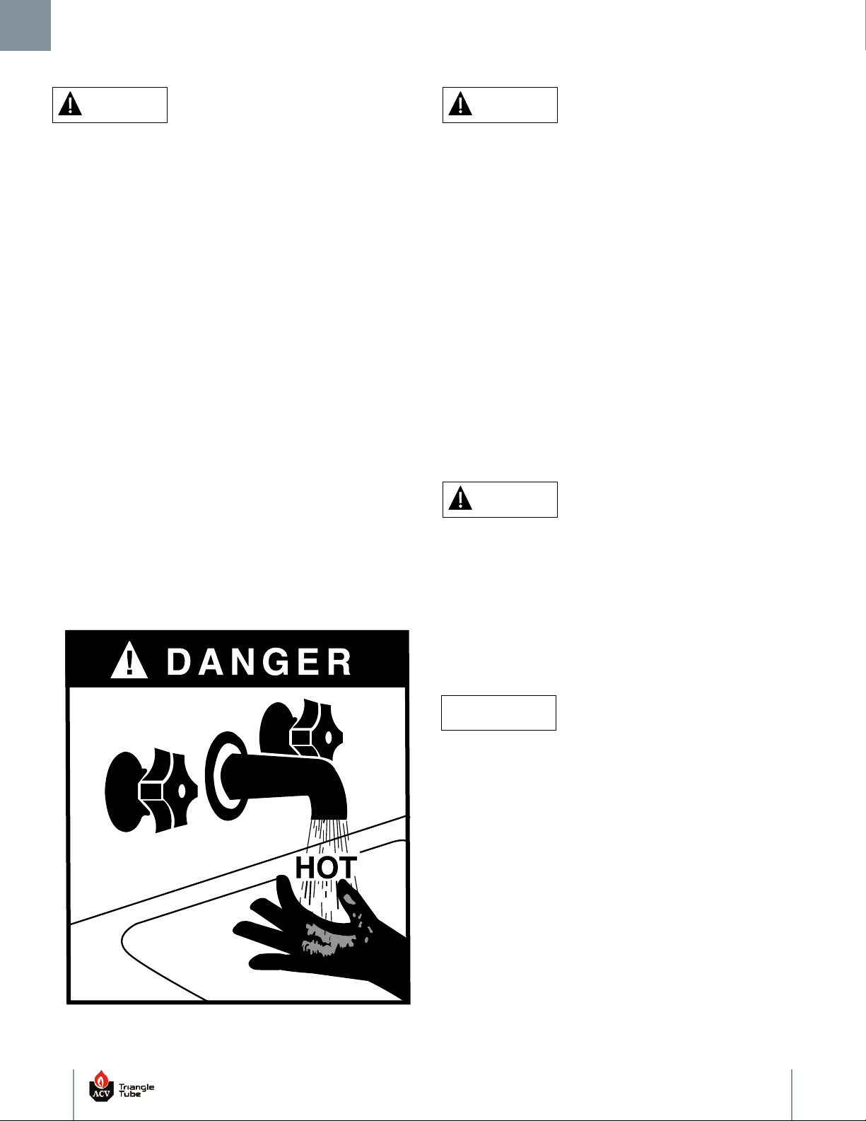
BURN
DANGER
OT WATER CAN SCALD!
H
ater temperature over 125°F [52°C] can cause severe
W
burns instantly or death from scalds.
• Children, disabled and elderly are at highest risk of
being scalded.
- Never leave them unattended in or near shower,
bathtub or sink.
- Never allow small children to use a hot water
faucet or draw their own bath.
• To avoid any potential scald hazard or if codes require
specific water temperatures at the hot water faucet,
the installer must:
- Install the factory supplied thermostatic mixing
valve at this appliance and ensure it is working
properly and
- Set the thermostatic mixing valve to the lowest
temperature which satisfies your hot water needs.
- Feel and adjust water temperature before bathing
or showering.
- Water drained from the system drain valves may
be extremely hot.
TO AVOID INJURY
- Make sure all connections are tight.
- Direct water flow away from any person
WARNING
byproduct of any gas fired appliance (stove, fireplace,
A
clothes dryer, water heater, furnace, boiler, etc.) is car-
on monoxide. In the absence of any state or local
b
codes requiring the installation of carbon monoxide detector and alarms, ACV-Triangle Tube recommends the
following:
Installation of a carbon monoxide detector and alarm that is•
wired on same electrical circuit as the boiler.
Installation of a carbon monoxide detector and alarm on each•
level of the building where there are bedrooms and in the living
area outside the bedrooms.
Installation of a carbon monoxide detector and alarm in the•
room that houses the appliance
Installation of a carbon monoxide detector and alarm with•
battery back up
Installation of a carbon monoxide detector and alarm that•
complies with NFPA 720.
WARNING
ACV-Triangle Tube accepts no liability for any damage,
injury or loss of life resulting from incorrect installation, alteration of any factory supplied parts or the use
of parts or fittings not specified by ACV-Triangle Tube. If
there is a conflict or doubt about the proper installation of the appliance or any factory supplied replacement parts, please contact the ACV-Triangle Tube
Technical Support Department.
1.4 Warranty
NOTICE
Warranty Registration Card must be filled out by the
customer and mailed within thirty (30) days of installation in order to gain warranty coverage.
2
Page 5
1. Product & Safety Information
WARNING
Failure to adhere to the guidelines on this page can re-
ult in substantial property damage, serious injury or
s
death
1.5 Service and Maintenance
To avoid electric shock, disconnect electrical supply before•
performing service or maintenance.
Allow the appliance to cool down prior to servicing to avoid•
severe burns
The CHALLENGER must be maintained as outlined in this•
manual and have at least annual service performed by a
qualified service technician to ensure appliance/system
reliability.
1.6 CHALLENGER Operation
Do not block flow of combustion air to the CHALLENGER. If the1.
combustion air blockage is easily accessible and removable,
then remove it. If blockage is not obvious and cannot be
removed, have the appliance and system checked by a qualified
service technician.
Do not allow contaminated air to enter the appliance’s2.
combustion air inlet. See Section II for more information.
The CHALLENGER is equipped with a low water cut off device.3.
The CH (central heating) system piping must be filled and
pressurized to 12 psig [0.8 bar] prior to startup. The appliance
will shut down if the pressure falls below 7 psig [0.5 bar].
Should overheating occur or the gas supply fails to shut off, DO4.
NOT turn OFF or disconnect the electrical supply to the pump.
Instead, shut off the gas supply at a location external to the
appliance.
Do not use this appliance if any part has been under water.5.
Immediately call a qualified service technician to inspect the
appliance and to replace any part of the control system and any
gas control, which has been under water.
1.7 Appliance & System Water
Have the appliance and system water chemistry checked at•
least annually by a qualified service technician.
Do not use petroleum-based cleaning or sealing compounds in•
the appliance or system. Gaskets and seals in the system may
be damaged. This can result in substantial property damage.
Do not use any product not specifically designed for hydronic•
heating systems. Serious damage to the appliance, piping
system, heating system, personnel, and/or property may occur.
Continual fresh makeup water will reduce the life of the•
CHALLENGER. Addition of oxygen can cause internal corrosion
in the system components. All leaks in the piping system must
be repaired at once to prevent makeup water.
Do not add cold water to a hot appliance. Thermal shock can•
cause premature failure to the appliance heat exchanger.
3
Page 6
2. Combustion Air - Prevention of Contamination
Section II: Combustion Air - Prevention of Contamination
.1 Combustion Air Contamination
2
WARNING
If the CHALLENGER combustion air inlet is located in
any area likely to cause or contain contamination, or if
products which could contaminate the air cannot be removed, the combustion air must be repiped and terminated to another location. Contaminated combustion
air will damage the appliance and the burner system
and can result in substantial property damage, serious
injury, or death.
WARNING
Do not operate a CHALLENGER if the combustion air
inlet is located near a laundry room or pool facility.
These areas will always contain hazardous contaminants.
Pool, laundry, common household, and hobby products
often contain fluorine or chlorine compounds. When
these chemicals pass through the burner and vent system, they can form strong acids. These acids can create corrosion of the heat exchanger, burner
components, and vent system, causing serious damage
and presenting a possible threat of flue gas spillage or
water leakage into the surrounding area.
Please read the information listed below. If contaminating chemicals are located near the area of the combustion air inlet, the installer should pipe the
combustion air inlet to an area free of these chemicals
per the CHALLENGER installation manual.
2.1.1 Potential Contaminating Products
Spray cans containing chloro/fluorocarbons•
ermanent Wave Solutions•
P
hlorinated wax •
C
Chlorine - based swimming pool chemicals / cleaners•
Calcium Chloride used for thawing ice•
odium Chloride used for water softening•
S
Refrigerant leaks•
Paint or varnish removers•
Hydrochloric acid / muriatic acid•
Cements and glues•
Antistatic fabric softeners used in clothes dryers•
Chlorine-type bleaches, detergents, and cleaning solvents•
found in household laundry rooms
Adhesives used to fasten building products and other similar•
products
2.1.2 Areas Likely to Contain these Products
Dry cleaning / laundry areas and establishments•
Beauty salons•
Metal fabrication shops•
Swimming pools and health spas•
Refrigeration repair shops•
Photo processing plants•
Auto body shops•
Plastic manufacturing plants•
Furniture refinishing areas and establishments•
New building construction•
Remodeling areas•
Garages with workshops•
4
Page 7
3. Maintenance Schedule
Section III: Maintenance Schedule
3.1 Service Technician
t least on an annual basis the following maintenance should be
A
erformed by a qualified service technician.
p
3.1.1 General
Attend to any reported problems.1.
Inspect the interior of the appliance jacket area; clean and2.
vacuum if necessary.
Clean the condensate drain assembly and fill with fresh water.3.
Check for leaks: water, gas, flue and condensate.4.
Verify flue vent piping and air inlet piping are in good condition,5.
sealed tight and properly supported.
Check appliance water pressure, piping and expansion tank.6.
Check control settings.7.
Check ignition electrode (sand off any white oxide; clean and8.
reposition).
Check ignition wiring and ground wiring.9.
Check all control wiring and connections.10.
Check burner flame pattern (stable and uniform).11.
3.2 Owner Maintenance
3.2.1 Periodic
Check the area around the appliance. 1.
Check and remove any blockage from the combustion air inlet2.
and ventilation openings.
Check the temperature and pressure gauge. 3.
3.2.2Monthly
Check vent piping.1.
Check combustion air inlet piping.2.
Check the pressure relief valve.3.
Check the condensate drain assembly.4.
Check automatic air vents (if used)5.
3.2.3Every 6 Months
Check appliance piping and gas supply piping for corrosion or1.
potential signs of leakage.
Operate the pressure relief valve.2.
WARNING
3.1.2 Poor Combustion or Performance
Clean heat exchanger and flue ways.1.
Remove burner assembly and clean inside of burner head using2.
compressed air only.
Once the maintenance items are completed, review the service with
the owner.
Follow the maintenance procedures given throughout
this manual. Failure to perform the service and maintenance or follow the directions in this manual can result
in damage to the CHALLENGER or system components
which can result in substantial property damage, serious injury or death.
5
Page 8
4. Maintenance Procedures
Section IV: Maintenance Procedures
WARNING
The CHALLENGER must be inspected and serviced an-
ually, preferably at the start of the heating season, by
n
a qualified service technician. In additioal, the maintenance and care of the appliance as outlined in Section
III and further explained in Section IV must be performed to assure maximum efficiency and reliability of
the appliance. Failure to service and maintain the CHALLENGER and the system components could result in
equipment failure which can cause substantial property
damage, personal injury or death.
NOTICE
The following information provides detailed instructions for completing the maintenance items outlined in
the maintenance schedule in Section III. In addition to
this maintenance, the CHALLENGER should be serviced
at the beginning of the heating season by a qualified
service technician.
4.1 Periodic Maintenance
4.1.1 Check the Surrounding Area
WARNING
To prevent potential of substantial property damage,
personal injury or death, eliminate all the materials
listed in Section II from the area surrounding the applianjce and from the vicinity of the combustion air inlet.
If contaminates are found:
- Remove products immediately from the area. If they
have been there for an extended period of time, call a
qualified service technician to inspect the appliance for
possible damage from acid corrosion.
- If products cannot be removed, immediately call a
qualified service technician to re-pipe the combustion
air inlet piping and locate the combustion air intake
from the contaminated areas.
Combustible/flammable materials - Do not store combustible1.
materials, gasoline or other flammable vapors or liquids near
the appliance. Remove immediately if found
Air contaminates - Products containing chlorine or fluorine, if2.
allowed to contaminate the combustion air, will cause acidic
condensate within the appliance. This will cause significant
damage to the appliance. Read the list of potential materials
listed in Section II of this manual. If any of these products are in
the room from which the appliance takes its combustion air,
they must be removed immediately or the combustion air intake
must be relocated to another area.
4.1.2 Check Combustion Air Inlets
Verify that ventilation air openings to the mechanical room are1.
open and unobstructed
Verify that the appliance’s vent termination and combustion air2.
intake are clean and free of obstructions. Remove any debris on
the air intake or flue exhaust openings. If removing the debris
oes not allow the appliance to operate correctly, contact your
d
qualified service technician to inspect the appliance and the
vent/combustion air system.
4.1.3 Check Temperature Display and Pressure Gauge
Ensure the pressure reading on the pressure gauge does not1.
exceed 25 psig [1.7 bar]. Higher pressure readings may indicate
a problem with the expansion tank.
Ensure the temperature on the display does not exceeed 194°F2.
[90°C]. Higher temperature readings may indicate a problem
with the operating thermostat controls.
Contact a qualified service technician if problem persists.3.
4.2 Monthly Maintenance
4.2.1 Check Vent Piping
Visually inspect the entire length of flue gas vent piping1.
including all joints and appliance adapter for any signs of
blockage, leakage or deterioration of gaskets or piping. Notify a
qualified service technician immediately if problems are found.
WARNING
Failure to inspect the venting system as noted and have
it repaired by a qualified service technician can result
in vent system failure, causing severe personal injury or
death.
4.2.2Check Combustion Air Inlet Piping
Visually inspect the combustion air inlet piping for any signs of1.
blockage. Inspect the entire length of the combustion air inlet
piping is intact and all joints are properly sealed.
Notify a qualified service technician if any problems are found.2.
4.2.3Check Pressure Relief Valve
Visually inspect the primary pressure relief valve and the relief1.
discharge pipe for signs of weeping or leakage.
If pressure relief valve often weeps, the expansion tank may not2.
be operating properly. Immediately contact a qualified service
technician to inspect the unit and system.
4.2.4Check Condensate Drain Assembly
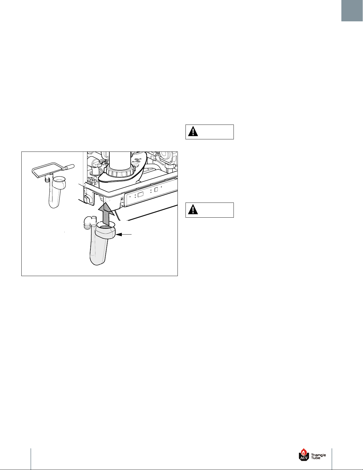
Ensure condensate trap assembly is firmly secured to the1.
bottom of the heat exchanger/unit as shown in Fig. 1 on page 7.
WARNING
Do not operate the CHALLENGER without condensate
trap assembly firmly installed on unit and filled with
water. If the trap is not installed and full of water, flue
gases can be emitted into the area and can cause serious injury or death.
6
Page 9
4. Maintenance Procedures
Condensate Trap
Assembly
* Carefully cut top of
condensate trap
assembly at location
shown.
*
While the appliance is operating, check the discharge end of the2.
condensate drain tubing. Ensure no flue gas is leaking from the
ondensate drain tubing by holding your fingers near the
c
opening.
If you notice flue gas leaking from the opening, this indicates a3.
ry condensate trap assembly. Contact a qualified service
d
technician to inspect the appliance and condensate line and
refill the condensate trap if problem persists regularly.
Ensure the condensate drain line is not blocked by pouring4.
water through the condensate drain assembly. The water should
flow out of the end of the drain line. If water does not appear at
the end of the drain line, contact a qualified service technician to
inspect and clean the condensate line.
To fill the condensate drain assembly, if necessary, slowly pour5.
water into the top of the trap assembly until water appears at
the end of the drain line. Stop filling.
4.3 6 - Month Maintenance
4.3.1 Check Water and Gas Piping
Remove the appliance front jacket panel and perform a gas leak1.
nspection per steps 1 through 6 of the Operating Instructions in
i
Section V. If gas odor or leak is detected, immediately shut down
the appliance following procedures in Section V. Call a qualified
service technician.
Visually inspect for leaks around the internal appliance water2.
connections and around the heat exchanger. Visually inspect the
external system piping, circulators and system components and
fittings. Immediately call a qualified service technician to repair
any leaks.
WARNING
Have leaks fixed at once by a qualified service technician. Failure to comply can result in substanial property
damage, serious injury or death.
4.3.2Operate Pressure Relief Valve
Before proceeding, verify that the relief valve outlet has been1.
piped to a safe place of discharge, avoiding any possibility of
scalding from hot water.
4.2.5Check Manual Air Vents
Open manual air vent on top of unit. Once air has stopped1.
escaping, close the manual air vent.
Fig. 1: Condensate Trap Installation
WARNING
To avoid water damage or scalding due to valve operation, a discharge line must be connected to the relief
valve outlet and directed to a safe place of disposal.
This discharge line must be installed by a qualified
service technician or heating/plumbing installer in accordance with the CHALLENGER Installation Manual.
The discharge line must be terminated so as to eliminate the possibility of severe burns or property damage
should the valve discharge.
Read the temperature and pressure gauge to ensure the system2.
is pressurized. Lift the relief valve top lever slightly, allowing
water to relieve through the valve and discharge piping.
If water flows freely, release the lever and allow the valve to seat.3.
Watch the end of the relief valve discharge pipe to ensure that
the valve does not weep after the line has had time to drain. If
the valve weeps, lift the lever again to attempt to clean the valve
seat. If the valve does not properly seat and continues to weep
afterwards, contact a qualified service technician to inspect the
valve and system.
If the water does not flow from the valve when you lift the lever4.
completely, the valve or discharge line may be blocked.
Immediately shut the appliance down per the instructions in
Section V. Call a qualified service technician to inspect the valve
and system.
7
Page 10
5. Operating Instructions
Section V: Operating Instructions
FOR YOUR SAFETY READ BEFORE LIGHTING
f you do not follow these instructions exactly, a fire or explosion can result causing substatial prop-
WARNING
I
erty damage, serious injury or loss of life.
A. This appliance does not have a pilot. It is equipped with an
ignition device which automatically lights the burner. DO NOT try
to light the burner by hand.
B. BEFORE OPERATING, smell all around the appliance area for gas.
Be sure to smell next to the floor because some gas is heavier
than air and will settle on the floor.
WHAT TO DO IF YOU SMELL GAS
Do not try to light any appliance•
Do not touch any electrical switch; do not use any phone in•
your building.
Immediately call your gas supplier from a neighbor’s phone.•
Follow the gas supplier’s instructions.
If you cannot reach your gas supplier, call the fire•
department.
OPERATING INSTRUCTIONS
STOP! Read the safety information above. This appliance is1.
equipped with an ignition device which automatically lights the
burner. DO NOT try to light the burner by hand.
Set room thermostat(s) to lowest setting. Turn the external2.
manual gas valve handle clockwise “CLOSE” (valve
handle shall be perpendicular to gas piping).
Turn “OFF” all electrical power to the appliance.3.
Remove the front jacket panel on the appliance.4.
Turn the external manual gas valve handle counter clockwise5.
to “OPEN” gas supply (valve handle shall be parallel to
gas piping).
Wait five (5) minutes to clear out any gas. If you then smell gas6.
in the jacket enclosure or around the appliance, STOP! Follow
“B” in the safety information above. If you don’t smell gas, go to
the next step.
C. Use only your hand to turn the external manual gas valve. Never
use tools. If the valve will not turn by hand, do not try to repair it.
Call a qualified service technician. Force or attempted repair may
result in a fire or explosion.
D. Do not use this appliance if any part has been under water.
Immediately call a qualified service technician to inspect the
appliance and to replace any part of the control system and any
gas control which has been under water.
Turn “ON” all electric power to the appliance. Push ON/OFF7.
button on the CHALLENGER control panel display until LED
above button is lit.
Set room thermostat(s) to desired setting(s).8.
The CHALLENGER control panel display will show a sequence9.
of numbers (1,2,3,4) as the right digit. Sequence digit 3 or 4
indicates the appliance is firing. A blank display means there is
no call for heat (all external thermostats are satisfied).
If the appliance will not operate with a call for heat and the10.
system piping is not hot, follow the instructions “To Turn Off Gas
to Appliance”, below and call your service technician or gas
supplier.
Replace the front jacket panel. Make sure the panel is seated11.
firmly in place and all mounting screws are tightened.
Set the room thermostat to lowest setting.1.
Turn “OFF” all electrical power to the appliance if service is to be2.
performed.
8
TO TURN OFF GAS TO APPLIANCE
Turn the external manual gas valve handle clockwise to3.
“CLOSE” (valve handle shall be perpendicular to gas piping).
Page 11
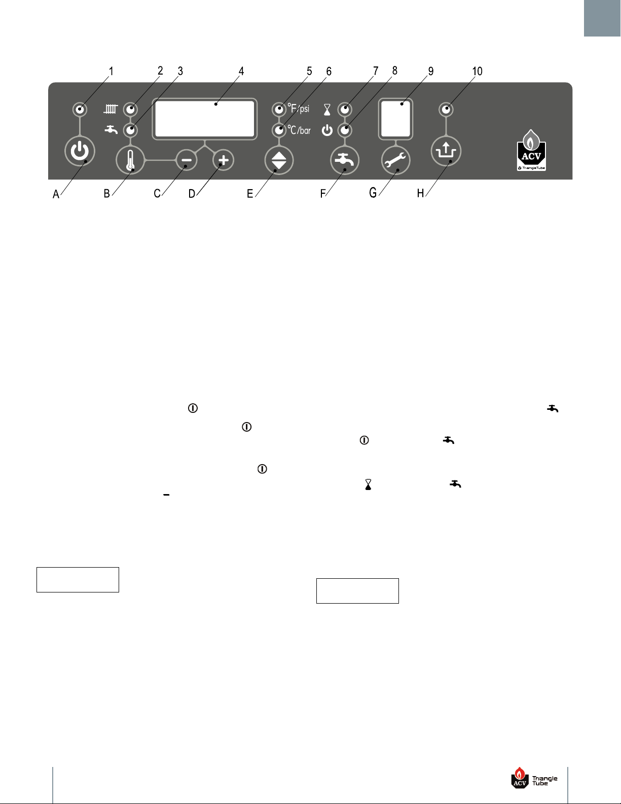
Section VI: Appliance Control Display
A. On/Off
B. Parameter
C. Decrease
D. Increase
E. Units U.S. customary or metric
F. DHW Function
G. Service
H. Reset/store
Read-Out
Operation
1. On/Off (Lit when on)
2. CH operation or setting maximum CH temperature
3. DHW operation or setting DHW temperature
4. Main display with temperature or water pressure
or fault code
5. Temperature ºF or pressure psi
6. Temperature ºC or pressure bar
7. DHW eco function
8. DHW minimum temperature function on
9. Operating display
10. Flashes to indicate fault
6. Appliance Control Display
F
F
O
/
N
O
e
c
n
a
i
l
p
p
A
1
.
6
.
n
o
t
t
u
b
F
F
O
/
N
O
e
h
t
g
n
i
s
u
F
F
O
/
N
O
e
c
n
a
i
l
p
p
a
n
r
u
T
.
1
F
F
O
/
N
O
e
h
t
e
v
o
b
a
D
E
L
n
e
e
r
g
e
h
t
,
N
O
s
i
e
c
n
a
i
l
p
p
a
n
e
h
W
.
2
u
s
s
e
r
p
r
e
t
a
w
e
h
t
w
o
h
s
l
l
i
w
y
a
l
p
s
i
d
n
i
a
m
e
h
T
.
t
i
l
e
b
l
l
i
w
n
o
t
t
u
b
.
d
n
a
m
e
d
t
a
e
h
o
n
s
i
e
r
e
h
t
n
e
h
w
”
P
“
y
b
d
e
w
o
l
l
o
f
O
/
N
O
e
h
t
e
v
o
b
a
D
E
L
n
e
e
r
g
e
h
t
,
F
F
O
s
i
e
c
n
a
i
l
p
p
a
e
h
t
n
e
h
W
.
3
h
t
d
n
a
”
F
F
O
“
w
o
h
s
l
l
i
w
y
a
l
p
s
i
d
n
i
a
m
e
h
T
.
t
i
l
e
b
t
o
n
l
l
i
w
n
o
t
t
u
b
.
w
o
h
s
l
l
i
w
y
a
l
p
s
i
d
g
n
i
t
a
r
e
p
o
s
t
i
n
U
2
.
6
U
m
o
r
f
s
t
i
n
u
d
e
y
a
l
p
s
i
d
e
h
t
e
g
n
a
h
c
o
t
n
o
t
t
u
b
w
o
r
r
a
n
w
o
D
/
p
U
s
s
e
r
P
i
l
e
b
l
l
i
w
D
E
L
i
s
p
/
F
°
e
h
T
.
)
r
a
b
&
C
°
(
c
i
r
t
e
m
o
t
)
i
s
p
&
F
°
(
y
r
a
m
o
t
s
u
C
.
s
t
i
n
u
c
i
r
t
e
m
r
o
f
t
i
l
e
b
l
l
i
w
D
E
L
r
a
b
/
C
°
r
o
s
t
i
n
u
y
r
a
m
o
t
s
u
C
.
S
.
U
E
C
I
T
O
N
6.3 DHW Operating Modes
Three DHW operating modes can be activated pressing the DHW
function button.
e
r
ON ( LED lit above the DHW button) The appliance will1.
always maintain a minimum heat exchanger temperature to
F
F
e
assure instant delivery of hot water.
ECO ( LED lit above the DHW button) The appliance2.
will learn when to maintain a minimum heat exchanger
temperature during times with typical domestic demands,
learned over the past 3 days of use.
.
S
.
r
o
f
t
OFF (no LED lit) - The appliance will not maintain a minimum3.
heat exchanger termperature. This will delay the delivery of hot
water.
BEST PRACTICE
-
t
a
r
e
p
o
r
o
y
a
l
p
s
i
d
n
i
a
m
e
h
t
f
i
d
e
g
n
a
h
c
e
b
t
o
n
n
a
c
s
t
i
n
U
.
g
n
i
h
s
a
l
f
s
i
y
a
l
p
s
i
d
g
n
i
In applications in which the DHW is not utilized or the
DHW demand is minimal, set the DHW function to OFF
9
Page 12
6. Appliance Control Display
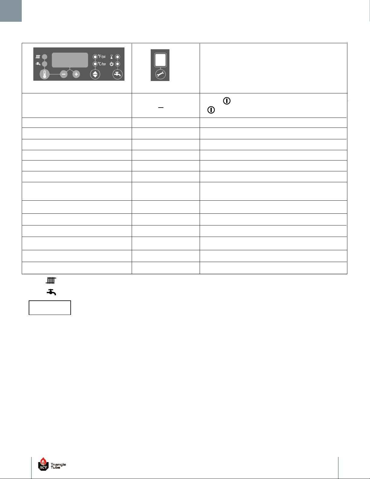
The
LED will be lit for CH (central heating call)
The
LED will be lit for DHW (domestic hot water call)
“X” represents temperature or pressure readings. When temperature is displayed it will be followed by “ºF” or “ºC” in the main display and
the appropriate LED will be lit. When pressure is displayed it will be followed by a “P” in the main display. Pressure can only be read when
the operating display is blank or shows a “A”.
* If factory installed CH Low Water Cut O (LWCO) is below 7 psig [0.5 bar] the main display will ash a soft lockout of
LOP (burner and CH primary pump is blocked) followed by the pressure reading. Once CH system pressure is increased
above 7 psig [0.5 bar] normal boiler operation will be restored. Check LWCO wiring if LOP ashes to 90 _P (PSI) or 6.0 _P
(bar).
** If the outdoor sensor is not installed the main display will display ODS when the boiler is in standby without a CH or
DHW call for heat or any errors. The lack of the outdoor sensor will not prevent the unit from operating on a CH or DHW
Function
Main Display
Operating Display
OFF
XXP
XXP
XXX
7
Press
No demand for heat
Control self-test
Fan pre purge or post purge cycle
Space Heating (CH) post pump cycle
XXX
XXX
6
A
1
Ignition sequence
XXX
2
Burner ON for space heating (CH)
XXX
LOP*
3
Burner ON for domestic hot water (DHW)
4
Burner ON for DHW pre-heating
Raise CH pressure above 7 psig [0.5 bar]
ODS**
Outdoor sensor not installed
POLE
Incoming line and neutral are reversed
Burner ON for freeze protection
8
9
Burner OFF due to reaching temperature
setpoint
button to turn appliance ON, LED light above
button will be lit when appliance is ON.
NOTICE
10
Page 13
6. Appliance Control Display
Adjustments
Description
Parameters
(Flashing)
Factory Settings
LED
(Flashing)
Installation type
0
186ºF [86ºC]
140ºF [60ºC]
0=Combi (Heat and DHW)
2=DHW only (no heating system required)
3=Heating only
CH pump continuous
0
0=Intermittent pump on for heat and post purge
1=Pump continously active except during DHW call or
if outside temperature is above parameter 7 with the
outdoor sensor installed - Warm Weather Shut Down
.
1=Heating + SMART/COMFORT I.F.W.H.
Min. supply temperature of the heat curve
86ºF [30ºC]
Adjustment range 60°F to 140°F [16ºC to 60ºC]
Min. outside temperature of the heat curve
0ºF [-18ºC]
Adjustment range -22°F to 50°F [-30ºC to 10ºC]
Max. outside temperature of the heat curve
64 ºF [18ºC]
Adjustment range 60°F to 78°F [16ºC to 26ºC]
CH pump post purge period
1
Adjustment range 0 to 15 minutes
DHW to CH anti-cycle time
0
Adjustment range 0 to 15 minutes
Anti-cycling period during CH operation
The anti-cycle time starts when burner shuts down during a CH call due to boiler water reaching the boiler set point temperature plus
a 6ºF [3ºC] dierential. The CH circulator will continue to operate while the burner is blocked.
0
Minimal switch-o time in CH operation
Adjustable from 0 to 15 minutes
1
2
5
6
7
8
o
P
Main Display
Operating
Display
Boiler set point temperature
DHW Setpoint
Adjustment range 86ºF to 194ºF [30ºC to 90ºC]
Adjustment range 104ºF to 149ºF [40ºC to 65ºC]
1
1
For installations with an optional ACV- Triangle Tube SMART Indirect Fired Water Heater (I.F.W.H.) piped o the primary loop, similar to
Figures 7 and 8 on page 15, parameter 1 should be set to 1. The I.F.W.H. aquastat should be wired to CHALLENGER’s X4-5 and X4-6
electrical connector, see Figure 12, page 21. The domestic I.F.W.H. circulator should be wired using the CHALLENGER’s 120 V terminals
4 (line), 5 (neutral) and 6 (ground). During a domestic call for heat on terminals X4-5 and X4-6, only the domestic I.F.W.H. circulator will
operate and the boiler’s target supply water temperature will shift to 186°F [86°C].
2
The DHW post pump function only applies when parameter 1 is set to a setting of 1 Heating & Smart I.F.W.H. and only occurs if no CH
call for heat is present.
The anti-cycling time starts at the end of the DHW call and blocks the burner and CH circulator. If DHW function is turned ON (” ” LED is
lit above the “ ” DHW button) or ECO is ON (” ” LED is lit abobve “ ” DHW button) then the burner will continue to re for DHW until a
minimum heat exchanger temperature is achieved. Burner and CH circulator will continue to be clocked until the remaining wait time
ends. This feature only applies if parameter 1 is set to 0.
3
2
DHW post pump
1
Adjustment range 0 to 15 minutes
9
3
DHW Flow Device Selection
0 = All CHALLENGER Solo
30 = CC105
36 = CC125 & CC125H
P.0
4
4
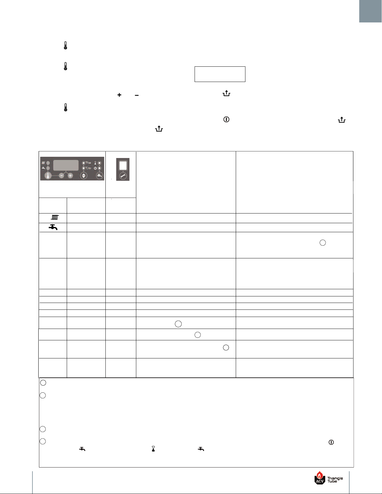
6.4 Setting the Appliance Parameters
button to close the parameter menu and store the changes. The
main display will go blank and a P will be displayed in the
Press the “ ” button at the display panel for approximately 21.
o 3 seconds until main display begins to flash.
t
perating display to indicate the parameter changes have been
o
stored.
Press the “ ” button repeatedly to scroll through the list of2.
arameters. The operating display will show the parameter
p
NOTICE
number and the main display will show the parameter setting.
To modify a parameter, press the “ ” or “ ” buttons.3.
If the reset button is not pressed within 30 seconds, the parameter menu is automatically closed and
Press the “ ” button to advance to the next parameter to be4.
changed.
After all parameters have been changed, press the reset5.
the changes are stored.
If the ON/OFF button is pressed prior to the
reset button, the parameter menu is closed and the
changes are NOT stored.
11
Page 14
6. Appliance Control Display
6.5 Error Mode
If a boiler fault occurs, the CHALLENGER enters a hard lockout
ondition which requires a manual reset by pressing the reset
c
. A hard lock is indicated by a flashing [E] on the operating
button
display as well as a flashing LED above the reset button. The error
ode is shown on the main display. The error must be corrected
c
before the control will reset.
CAUTION
The appliance freeze protection feature is disabled during a Hard Lockout, however the CH circulator will operate.
CAUTION
During a hard lockout or low water condition the appliance will not re-start without service. If the heating
system is left unattended in cold weather appropriate
safeguards or alarms should be installed to prevent
property damage.
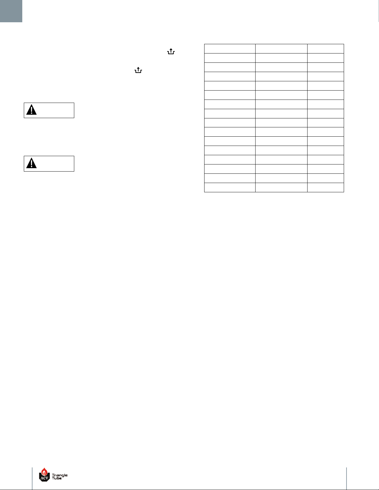
Table 1: 12 kOhm NTC Sensor Resistance
Temperature (°F) Temperature (°C) NTC (kOhm)
-22 -30 171.70
4 -20 98.82
-
14 -10 58.82
32 0 36.10
50 10 22.79
68 20 14.77
78 25 12.00
86 30 9.81
104 40 6.65
122 50 4.61
140 60 3.25
158 70 2.34
176 80 1.71
194 90 1.27
212 100 0.95
6.6 Fluctuating DHW Temperature
Domestic water temperatures can fluctuate when the domestic hot
water flow is less than 0.7 gpm. The fluctuation is due to the
interaction between the minimum domestic hot water flow rate of 0.5
gpm and the domestic hot water mixing valve. As the domestic hot
water leaving the appliance approaches the domestic hot water
mixing valve setting, the mixing valve reduces the amount of hot
water through the appliance. The appliance cycles off when water flow
through the appliance dips below 0.5 gpm. To improve the domestic
hot water performance at low flows it is recommended to reduce the
domestic hot water temperature setpoint on the control down from
140°F (60°C) to 125°F (52°C), see Section 12.8 in the CHALLENGER
Combit Installation Manual, or to turn domestic function on the
control to ON or ECO, see Section 6.3.
12
Page 15
6. Appliance Control Display
10, 11, 12,
1, 28
4
0
2
29,30
5
6
8
13, 14
CH supply sensor fault
•
Check wiring for break
•
Check for proper flow direction
• Replace supply sensor
• E10 Open sensor
• E 11 Shorted sensor
•
E12 Decreased too quickly
•
E13 Increased too quickly
•
E14 Stuck
• Replace return sensor
• E 20 Open sensor
•
E 21 Shorted sensor
• E22 Decreased too quickly
• E23 Increased too quickly
• E24 Stuck
2
0, 21, 22,
23, 24
CH return sensor fault
•
Check wiring for break
•
Check for proper flow direction
Sensor fault after self check
• Replace supply and/or return sensors
Temperature too high
• Air in system
• Pump not running
• Insufficient water flow, shut off valves closed, p ump setting too low
• Flow switch sticking or miss-installed
• Check for wiring error
Supply sensor and
return sensor
swapped
• Check for proper flow direction
• Replace supply and/or return sensors
No flame signal
• Manual gas shut off valve closed
• Remove air from gas pipe
• Gas supply pressure too low
• Gas valve or ignition unit not powered
• Incorrect ignition gap
• Check adjustment of gas valve
Poor flame signal
• Condensate drain blocked
• Check adjustment of gas valve
Flame detection fault
• Replace ignition cable
• Replace ignition unit at gas valve
• Replace boiler controller
Incorrect fan speed
• Fan rubbing on c abinet
• Wiring between fan and cabin et
• Check wiring for poor contact
• Replace fan
Gas valve relay fault
• Replace boiler controller
Operating
Display
(Flashing)
Main Display
Possible Solution
Error Description
E
18, 19
Flue sensor fault
• E18 Open sensor
• E19 Shorted sensor
• Check/Replace flue sensor
E
7,16, 17
DHW sensor fault
• E16 Shorted sensor
• E17 Open sensor
• Check/replace DHW sensor
• E7 Excessive temperature
• Check gas orifice
• Check combustion settings
E
50F
Improper power frequency
• Verify ground
• Frequency should be between 45 and 65 Hz
E
E
E
E
E
E
E
E
E
E101
Flue gas temperature
approaching limit
• Supply water temperature too high
• Check positioning of flue gas sensor
• Ambient temperature too high
• Check heat exchanger for debris
• Replace flue gas temperature sensor
E105 Outdoor Sensor Short
• Check wiring
• Replace outdoor sensor
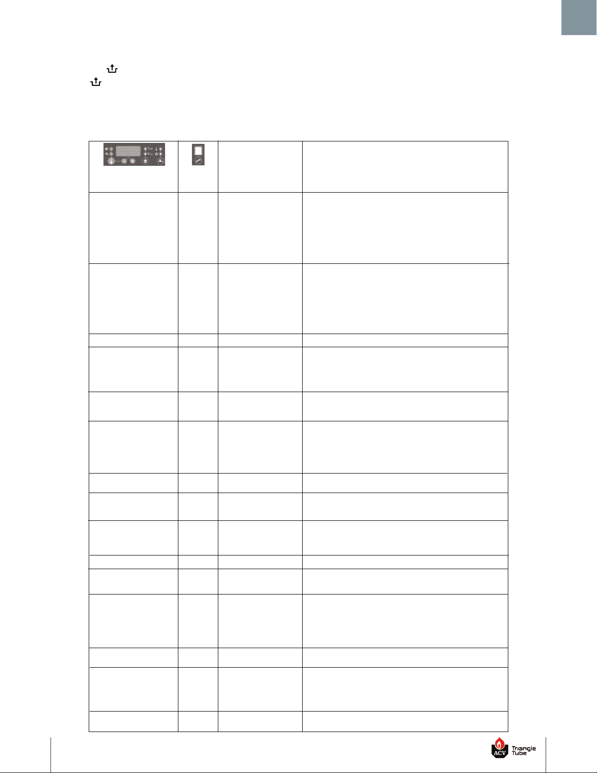
6.7 Error Codes
Red LED above the reset button will flash. Correct condition first,
then press the reset button.
6.8 Warning Codes
In situations where the boiler takes a preventative action without
going into a hard lockout, a warning code flashes in the main display.
he warning code will alternate with the normally displayed value.
T
The cause of the warning code should be investigated and corrected
mmediately to return the boiler to full functionality.
i
13
Page 16
7. Replacement Parts
T
S
U
Section VII: Replacement Parts
WARNING
Replacement parts must be purchased through a local ACV - Triangle Tube distributor. When ordering parts please provide the
odel number and description and/or part number of replacement part.
m
Use only genuine ACV - Triangle Tube replacement parts to ensure warranty coverage and to avoid damage to appliance and im-
roper operation of appliance. Contact ACV - Triangle Tube at 856-228-8881 or www.triangletube.com for a list of distributors
p
nearest you.
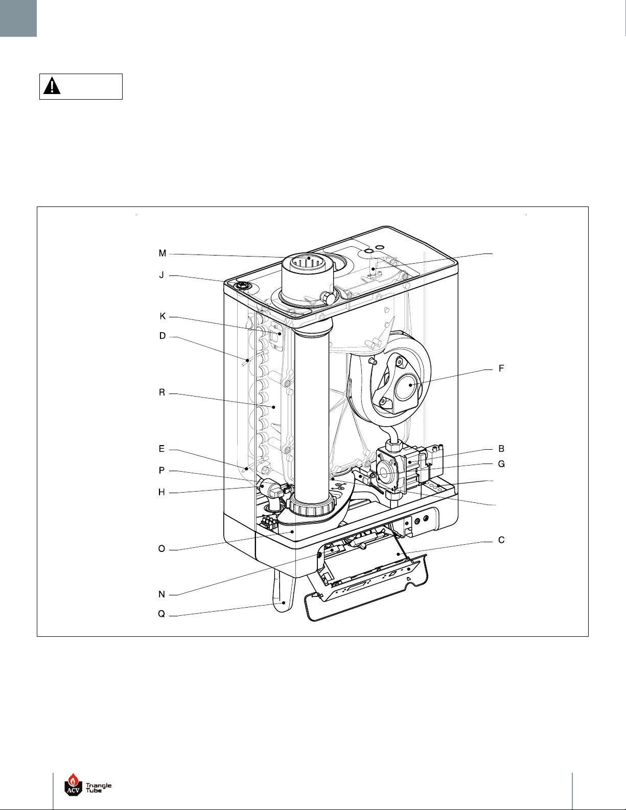
7.1 Internal Components
Fig. 2: CHALLENGER Internal Components
B. Gas Valve J. Pressure Relief & Air Vent Connection Q. Condensate Drain Trap Assembly
C. Control/Display K. Sight Glass R. Heat Exchanger
D. CH Supply Sensor
E. CH Return Sensor T. Line Voltage Terminal Strip
F. Blower N. Low Voltage/Terminal Strip (X4) U. Flue Sensor
G. DHW Flow Sensor O. Condensate Pan
H. LWCO/CH Pressure Sensor P. DHW Sensor
Vent/Air Adapter (80/125 Concentric
M.
Option shown - 3" Standard, not shown)
S. Igniter
14
Page 17
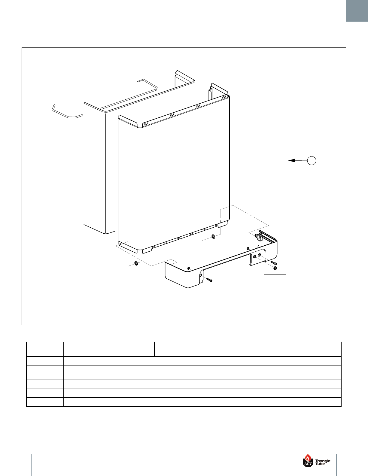
7.2 Front Door
3
7. Replacement Parts
Fig. 3: CHALLENGER Front Door
Item
Part Number
CC105
Part Number
CC125
Part Number
CC125H
Description
1 CCRKIT04 Wall Bracket Assembly (Not Shown)
2 CCRKIT05
Pipe Connectors & Brackets Assembly
(Not Shown)
2A CCFTG01 Connector Pipe CH (Not Shown) - 1/Kit
2B CCFTG02 Connector Pipe DHW (Not Shown) - 1/Kit
3 CCRKIT07 CCRKIT08 Front Door Assembly
15
Page 18
7. Replacement Parts
2
2
3
1
2
3
3
4
3
7.3 Vent Components
Fig. 4: CHALLENGER Vent Components
Item
1
Part Number
CC105
Part Number
CC125
CCRKIT09
CCRKIT35
Part Number
CC125H
Description
80/125 Concentric Vent/Air Adapter
Assembly (Optional - Shown)
3" Vent/Air Adapter Assembly
(Standard - Not shown)
2 CCRKIT11 CCRKIT12 Vent Assembly
3 CCRKIT13 Condensate Collector Assembly
4 CCRKIT14 CCRKIT14A Condensate Trap Assembly
5 CCRKIT41 Condensate Collector/Trap Gasket
6 CCRKIT36 Flue Sensor
16
Page 19
9
1
3
2
8
11
6
4
10
5
7
4
12
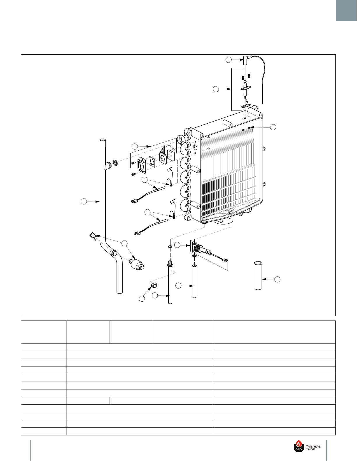
7.4 Heat Exchanger Components
7. Replacement Parts
Item
Part Number
CC105
Fig. 5: CHALLENGER Heat Exchanger Components
Part Number
CC125
Part Number
CC125H
Description
1 CCRKIT15 Igniter Assembly
2 CCCLB01 Ignition Cable
3 CCRKIT16 Sight Glass Assembly
4 CCRKIT17 CH Sensor Assembly - 1/Kit
5 CCSENS02 DHW Temperature Sensor
6 CCRKIT56 DHW Flow Sensor Assembly
7 CCRKIT19 LWCO / CH Pressure Sensor Assembly
8 CCRKIT21 CCRKIT22 CH Supply Pipe Assembly
9 CCRKIT23 CH Return Pipe Assembly
10 CCRKIT26 DHW Hot Water Outlet Pipe
11 CCRKIT57 DHW Cold Water Inlet Pipe
12 CCRKIT40 Igniter Bushings - 2/Kit
17
Page 20
7. Replacement Parts
5
1
2
3
7
6
4
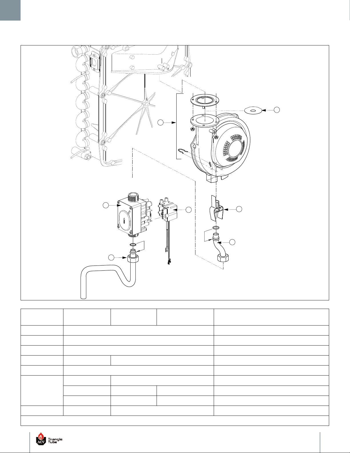
7.5 Blower & Gas Valve Components
Fig. 6: Blower & Gas Valve Components
Item
Part Number
CC105
Part Number
CC125
Part Number
CC125H
Description
1 CCRKIT59 Ignition Transformer Assembly
2 CCRKIT60 Gas Valve Assembly
3 CCRKIT31 Lower Gas Pipe Assembly
4 CCRKIT61 CCRKIT62 Upper Gas Pipe Assembly
5 CCRKIT32 Blower Assembly
CCRKIT45 N/A Venturi 406
6
N/A N/A CCRKIT63 Venturi 471
N/A CCRKIT46 N/A Venturi 362
7 CCRKIT48 N/A Blower Outlet Orifice 1-7/16" (37 mm)
N/A = Not Applicable
18
Page 21
1
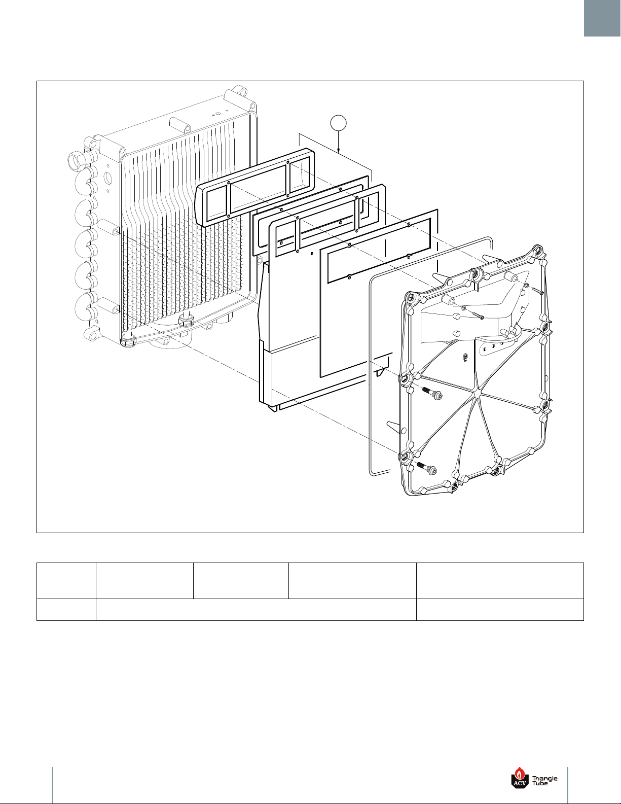
7.6 Burner Components
7. Replacement Parts
Fig. 7: Burner Components
Item
Part Number
CC105
1 CCRKIT33 Burner Assembly
Part Number
CC125
Part Number
CC125H
Description
19
Page 22
7. Replacement Parts
3
4
2
1
6
5
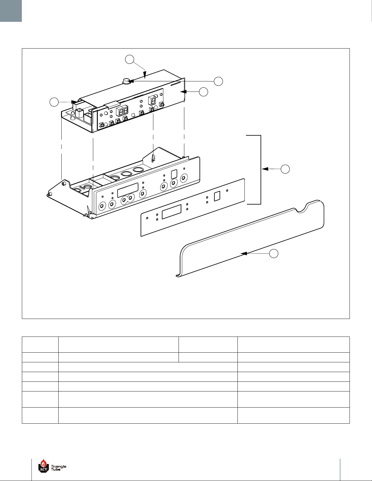
7.7 Control Components
Fig. 8: Control Components
Item
1 CCRKIT53 CCRKIT54 Control/Display
2 CCCS01 Plastic Control Housing
3 CCRKIT34 Flip Panel
4 CCFUSE01 Fuse - 1/Kit
5 CCRKIT43
6 CCRKIT44
Part Number
CC105 & CC125
Part Number
CC125H
Description
Connector - X4, 24V, 9 Pin
(Not Shown)
Connector - X2, 120V, 8 Pin
(Not Shown)
20
Page 23

Section VIII: Notes
8. Notes
21
Page 24
Additional Quality Water Heating Equipment Available From
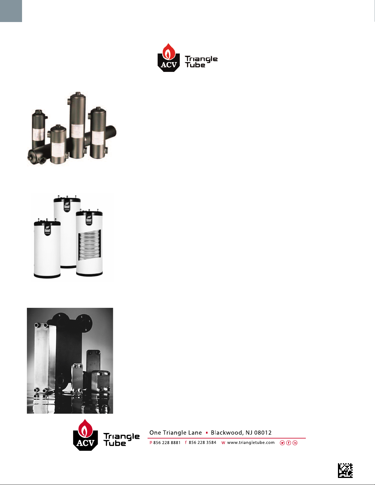
Maxi-Flo Pool and Spa Heat Exchangers
Constructed of high quality corrosion resistant stainless steel (AISI 316) or•
titanium
Specially designed built-in flow restrictor to assure maximum heat exchange•
Compact and light weight•
Available in 8 sizes that can accommodate any size pool or spa•
SMART/COMFORT Indirect Fired Water Heaters
Exclusive Tank-in-Tank design•
Stainless steel construction•
TTP Brazed Plate Heat Exchangers
For domestic water, snow melting, radiant floor, and more•
Plates made of stainless steel, with 99.9% copper brazing ensuring a high•
resistance to corrosion.
Self Cleaning / Self Descaling•
Computerized sizing available from ACV - Triangle Tube•
Available in capacities from 25,000 BTUH to 5,000,000 BTUH•
Self cleaning/Self descaling heat exchanger•
SMART available in 7 sizes; COMFORT available in 2 sizes•
SMART: Limited LIFETIME residential warranty / Limited 6 year commercial•
warranty
COMFORT: Limited 10 year warranty•
88350705
 Loading...