

Page 1

IMPORTANT:
READ INSTRUCTIONS CAREFULLY BEFORE ATTEMPTING TO
INSTALL, OPERATE OR SERVICE THIS FAN. FAILURE TO COMPLY WITH INSTRUCTIONS
COULD RESULT IN PERSONAL INJURY AND/OR PROPERTY DAMAGE.
RETAIN INSTRUCTIONS FOR FUTURE REFERENCE.
Page 1
– – – – – – – – – – – – – – – – – – – – – – – –
CAUTION - SAFETY RULES
– – – – – – – – – – – – – – – – – – – – – – – –
WARNING - TO REDUCE THE RISK OF FIRE,
ELECTRIC SHOCK, OR INJURY TO PERSONS,
OBSERVE THE FOLLOWING:
Use this unit only in the manner intended by the manufacturer. If you have questions, contact the manufacturer.
Before servicing or cleaning unit, switch power off at service
panel and lock service disconnecting means to prevent power
from being switched on accidentally. When the service disconnecting means cannot be locked, securely fasten a prominent warning device, such as a tag, to the service panel.
Installation Work And Electrical Wiring Must Be Done By
Qualified Person(s) In Accordance With All Applicable Codes
And Standards, Including Fire-rated Construction.
Permanent Grounding must be used.
DO NOT USE AN EXTENSION CORD.
WARNING: TO REDUCE THE RISK OF FIRE OR ELECTRICAL
SHOCK, DO NOT USE THIS FAN WITH ANY SOLID-STATE
FAN SPEED CONTROL DEVICE.
CAUTION - For General Ventilating Only, Do Not Use To
Circulate Hazardous Or Explosive Materials And Vapors.
INSTALLATION RECORD
Please complete for future use.
Model #
_ _ _ _ _ _ _ _ _ _ _ _ _ _ _ _ _ _ _ _ _ _ _
Serial #
_ _ _ _ _ _ _ _ _ _ _ _ _ _
Purchased from
_ _ _ _ _ _ _ _ _ _ _ _ _ _ _ _ _ _ _ _ _ _ _ _ _ _ _ _ _ _ _ _ _ _ _ _ _ _
Date Purchased
____________
Date installed
_ _ _ _ _ _ _ _ _ _ _ _ _ _
TRIANGLE ENGINEERING OF ARKANSAS, INC.
E-mail: mail@trianglefans.com • Website: www. t r i a n g l e f a n s . c o m
1101 North Redmond Road • Jacksonville, Arkansas 72076 • (501) 982-7558 • Fax (501) 982-5691 • 1-800-255-9014
JetAire Shown
with Optional
Oscillator and
Pedestal
Patent Pending
Page 2
Page 2
230/460/60/3 INSTALLATION
If supplied with 230 or 460 Volt Three Phase fan
m o t o r, your fan will re q u i re connection directly to
the power source since product is supplied without a plug.
NOTE: ALTHOUGH THE FAN MOTOR IS THREE
PHASE, THE OSCILLATOR MOTOR IS SINGLE
PHASE AND WILL REQUIRE CONNECTION OF
TWO WIRES PLUS THE GROUND.
If power source is in a moist or wet area, all
components and connections must be water pro o f .
NOTICE: READ ALL INSTRUCTIONS
BEFORE STARTING ANY INSTALLATION AND WIRING.
ELECTRICAL WIRING
CAUTION
- If this product is to be use out-of doors or in areas
of extreme moisture, all electrical wiring and components must
be weather-proof or in moisture-proof enclosures and comply
with local and national electrical codes. Installation and wiring
must be done by a qualified person.
115/230/60/1 INSTA L L AT I O N
If your fan or fan/oscillator is supplied with 115 or 230 Vo l t
single-phase motors, it is recommended that a WEAT H E R P R O O F, GROUNDED electrical outlet be installed close to the
p rod uct. This will permit the plug(s) furnished with the JetAire
to be conveniently removed should your fan re q u i re serv i c e .
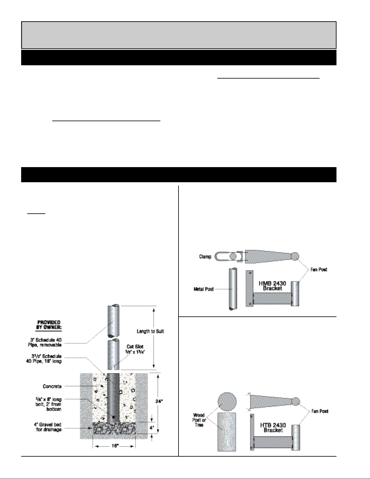
PREPARATION
IN-GROUND INSTA L L ATION
WITH REMOVABLE POST:
• NOTE: It may be desirable to install electrical
through the center of the post. If so, this must be
done prior to installation of concrete.
• Prepare hole in ground as shown below. Depth
should be below frost line or a minimum of 24".
• Cut removable pipe to length and cut slot in bottom
as shown. Pipe may be any length to meet your
requirements. Before installing pipe, it should be
painted with a good grade of rust inhibitor.
• Install electrical and JetAire.
ROUND METAL POST:
• This installation requires the OPTIONAL "HMB 2430"
HORIZONTAL MOUNTING BRACKET.
• Using the proper size clamps for your specific column,
(clamps not furnished with bracket) mount Horizontal
Mounting Bracket as shown below.
• Once bracket is installed, proceed with electrical wiring
and installation of JetAire.
WOOD POST OR TREE MOUNT:
• For wood post or tree mount, it is necessary to purchase the OPTIONAL "HTB 2430" TREE/POST MOUNTING BRACKET.
• Install bracket at desired height above ground/floor
using 1⁄2" x 6" lag screws or 1⁄2" through bolts, washers
and nuts.
• Once bracket is installed, proceed with electrical wiring
and installation of JetAire.
Page 3

Page 3
JETAIRE MOUNTING BRACKET ASSEMBLY
INVERTED BEAM MOUNTING
This installation requires the purchase of the
OPTIONAL MODEL "VMB 2430"
VERTICAL MOUNTING BRACKET
(Note the "D" dimension as shown on Manufacturer's Literature)
– – – – – – – – – – – – – – – – – –
• Weld or bolt Hanger Bracket to horizontal beam.
Bracket must be located a minimum of 24" from
walls and other vertical obstructions.
• Using ONE 1⁄2" x 1" bolt with nut, attach Upper
Support to Hanger Bracket.
• Attach extension tube to Upper Support with
TWO 1⁄2" x 1" bolts and nuts.
• Lift JetAire into position and attach the Lower
Support to Extension Tube with TWO 1⁄2" x 1"
bolts and nuts.
• Turn JetAire in desired direction and place 5⁄16"
x 1" carriage bolts and nuts in slots of Hanger
Bracket and Upper Support. BE SURE ALL
BOLTS AND NUTS ARE TIGHT.
• Loop safety cable around fan yoke as shown on
right and attach opposite end to beam.
The "HV" fan(s) you purchased are supplied with
either the Standard Mounting Bracket or the Optional
Oscillating Assembly.
• To attach either of these to the fan yoke, simply
match the four holes in the yoke plate to the four
holes in either the cap(2) or the oscillator
assembly.
• Insert the four bolts (3), install nuts and tighten.
• Your JetAire may now be assembled to the InG round Post, Pedestal, Horizontal or Tre e
Mounting Bracket.
• NOTE: Before attempting to install your fan on
any of these mounts, it will be necessary to
loosen set screw (1), as shown on right, so that
the point does not protrude into the I.D. of the
cap.
• With the JetAire installed on the mount and facing the desired direction, tighten set screw.
TILT ADJUSTMENT
To tilt the JetAire, loosen bolts (4) on each side of
yoke, position fan and retighten bolts.
Page 4
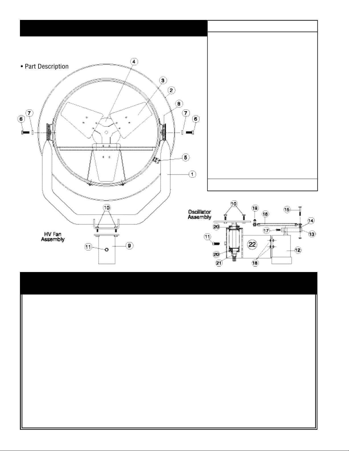
No. Description ...................................Qty.
1. Yoke Assembly................................1
2. Barrel Assembly ..............................1
3. Blade Assembly...............................1
4. Motor ..............................................1
5. Strain Relief Bushing.......................1
6.
1
⁄2" x 1" Hex Head Bolt.....................2
7.
1
⁄2" Flat Head Washer.......................2
8. Rubber Friction Washer...................2
9. Cap Assembly..................................1
10.3⁄8" Mounting Bolt & Nut .................4
11. Set Screw ........................................1
12. Oscillator Motor ..............................1
13. Crank Arm .......................................1
14. Spacer .............................................2
15. Hex Bolt & Nut ................................1
16. Linkage Assembly ...........................1
17. Set Screw ........................................1
18. Hex Bolt & Nut ................................4
19. Hex Bolt & Nut ................................1
20. Bearing & Seal.................................2
21. Self Locking Hex Head Nut..............1
22. Entire Oscillator Assembly...............1
REPAIR & REPLACEMENT PARTS
Page 4
LIMITED THREE YEAR WARRANTY
Do not return product to original place of purchase.
11/05
WHEN ORDERING PARTS, GIVE:
• Fan Model Number
• Fan Serial Number
• Part Description
Triangle Engineering of Arkansas, Inc. (Manufacture r )
w a r rants, from the date of purchase, to the original purchaser only, that the product manufactured by Manufacture r
is free from defects in material and workmanship for a period of THREE (3) YEARS. Motors, capacitors, v-belts and
switches are excluded from this warr a n t y , but shall have a
limited one year warranty from date of purchase to the original purc h a s e r .
If a failure of the product occurs, contact the Manufacture r
at: 1-800-255-9014 and give the model number of the pro d uct, the purchase date, and a description of the problem to
the customer service agent.
Once the problem is diagnosed, and proof of purchase date
is verified, Manufacturer will have the option of shipping the
n e c e s s a r y repair part(s) to the Customer, freight prepaid or
having the product re t u r ned to Manufacturer for repair or
re p l a c e m e n t . If the product is re t u r ned to the Manufacture r ,
Customer is responsible for prepayment of all inbound fre i g h t
c h a r ges. Upon repair or replacement, which shall be at the
d i s c r etion of Manufacture r , the Manufacturer will prepay all
outbound freight charges for the re t u r n of the product to the
c u s t o m e r. However, if Manufacturer finds product to be in
operating condition and no problems are diagnosed, pro d u c t
will be re t u r ned to customer freight collect.
THERE ARE NO WARRANTIES WHICH EXTEND BEYOND
THE DESCRIPTION ON THE FACE HEREOF.
Except as provided by this express warr a n t y , the goods are
sold “as is” without any implied warr a n t i e s .
This limited warranty does not cover labor to replace warrantied parts or motors, nor does it cover failure of the
installer to provide adequate ventilation to meet minimum
exhaust re q u i rements, damage resulting from accident, misuse or abuse, lack of proper maintenance, improper installation, affixing of any parts or attachments not authorized by
M a n u f a c t u r e r , or loss of parts.
In no event shall Manufacturer be liable for any special, incidental, or consequential damages; which may result from any
defect in material or workmanship.
It is expressly understood that Buyer’s sole and exclusive
remedy shall be repair or replacement of defective parts, and
that Triangle Engineering shall not be liable for injury to persons or pro p e r t y . Should the goods prove so defective, howe v e r, as to pr eclude the remedying of warranted defects by
repair or replacement, the Buyer’s sole and exclusive re m e d y
shall then be a refund of the purchase price.
This warranty gives you specific legal rights, and you may
also have other rights which vary from state to state.
 Loading...